EP4495431A1 - Hydraulic actuator and method for operating - Google Patents
Hydraulic actuator and method for operating Download PDFInfo
- Publication number
- EP4495431A1 EP4495431A1 EP23185853.1A EP23185853A EP4495431A1 EP 4495431 A1 EP4495431 A1 EP 4495431A1 EP 23185853 A EP23185853 A EP 23185853A EP 4495431 A1 EP4495431 A1 EP 4495431A1
- Authority
- EP
- European Patent Office
- Prior art keywords
- chamber
- control means
- flow control
- piezoelectric elements
- piston
- Prior art date
- Legal status (The legal status is an assumption and is not a legal conclusion. Google has not performed a legal analysis and makes no representation as to the accuracy of the status listed.)
- Pending
Links
Images



Classifications
-
- F—MECHANICAL ENGINEERING; LIGHTING; HEATING; WEAPONS; BLASTING
- F15—FLUID-PRESSURE ACTUATORS; HYDRAULICS OR PNEUMATICS IN GENERAL
- F15B—SYSTEMS ACTING BY MEANS OF FLUIDS IN GENERAL; FLUID-PRESSURE ACTUATORS, e.g. SERVOMOTORS; DETAILS OF FLUID-PRESSURE SYSTEMS, NOT OTHERWISE PROVIDED FOR
- F15B7/00—Systems in which the movement produced is definitely related to the output of a volumetric pump; Telemotors
- F15B7/001—With multiple inputs, e.g. for dual control
-
- B—PERFORMING OPERATIONS; TRANSPORTING
- B64—AIRCRAFT; AVIATION; COSMONAUTICS
- B64C—AEROPLANES; HELICOPTERS
- B64C25/00—Alighting gear
- B64C25/02—Undercarriages
- B64C25/08—Undercarriages non-fixed, e.g. jettisonable
- B64C25/10—Undercarriages non-fixed, e.g. jettisonable retractable, foldable, or the like
- B64C25/18—Operating mechanisms
- B64C25/22—Operating mechanisms fluid
-
- B—PERFORMING OPERATIONS; TRANSPORTING
- B64—AIRCRAFT; AVIATION; COSMONAUTICS
- B64C—AEROPLANES; HELICOPTERS
- B64C25/00—Alighting gear
- B64C25/02—Undercarriages
- B64C25/08—Undercarriages non-fixed, e.g. jettisonable
- B64C25/10—Undercarriages non-fixed, e.g. jettisonable retractable, foldable, or the like
- B64C25/18—Operating mechanisms
- B64C25/24—Operating mechanisms electric
-
- F—MECHANICAL ENGINEERING; LIGHTING; HEATING; WEAPONS; BLASTING
- F15—FLUID-PRESSURE ACTUATORS; HYDRAULICS OR PNEUMATICS IN GENERAL
- F15B—SYSTEMS ACTING BY MEANS OF FLUIDS IN GENERAL; FLUID-PRESSURE ACTUATORS, e.g. SERVOMOTORS; DETAILS OF FLUID-PRESSURE SYSTEMS, NOT OTHERWISE PROVIDED FOR
- F15B15/00—Fluid-actuated devices for displacing a member from one position to another; Gearing associated therewith
- F15B15/08—Characterised by the construction of the motor unit
- F15B15/14—Characterised by the construction of the motor unit of the straight-cylinder type
- F15B15/149—Fluid interconnections, e.g. fluid connectors, passages
-
- F—MECHANICAL ENGINEERING; LIGHTING; HEATING; WEAPONS; BLASTING
- F15—FLUID-PRESSURE ACTUATORS; HYDRAULICS OR PNEUMATICS IN GENERAL
- F15B—SYSTEMS ACTING BY MEANS OF FLUIDS IN GENERAL; FLUID-PRESSURE ACTUATORS, e.g. SERVOMOTORS; DETAILS OF FLUID-PRESSURE SYSTEMS, NOT OTHERWISE PROVIDED FOR
- F15B15/00—Fluid-actuated devices for displacing a member from one position to another; Gearing associated therewith
- F15B15/18—Combined units comprising both motor and pump
-
- F—MECHANICAL ENGINEERING; LIGHTING; HEATING; WEAPONS; BLASTING
- F15—FLUID-PRESSURE ACTUATORS; HYDRAULICS OR PNEUMATICS IN GENERAL
- F15B—SYSTEMS ACTING BY MEANS OF FLUIDS IN GENERAL; FLUID-PRESSURE ACTUATORS, e.g. SERVOMOTORS; DETAILS OF FLUID-PRESSURE SYSTEMS, NOT OTHERWISE PROVIDED FOR
- F15B15/00—Fluid-actuated devices for displacing a member from one position to another; Gearing associated therewith
- F15B15/20—Other details, e.g. assembly with regulating devices
- F15B15/26—Locking mechanisms
-
- F—MECHANICAL ENGINEERING; LIGHTING; HEATING; WEAPONS; BLASTING
- F15—FLUID-PRESSURE ACTUATORS; HYDRAULICS OR PNEUMATICS IN GENERAL
- F15B—SYSTEMS ACTING BY MEANS OF FLUIDS IN GENERAL; FLUID-PRESSURE ACTUATORS, e.g. SERVOMOTORS; DETAILS OF FLUID-PRESSURE SYSTEMS, NOT OTHERWISE PROVIDED FOR
- F15B21/00—Common features of fluid actuator systems; Fluid-pressure actuator systems or details thereof, not covered by any other group of this subclass
- F15B21/08—Servomotor systems incorporating electrically operated control means
- F15B21/082—Servomotor systems incorporating electrically operated control means with different modes
-
- F—MECHANICAL ENGINEERING; LIGHTING; HEATING; WEAPONS; BLASTING
- F15—FLUID-PRESSURE ACTUATORS; HYDRAULICS OR PNEUMATICS IN GENERAL
- F15B—SYSTEMS ACTING BY MEANS OF FLUIDS IN GENERAL; FLUID-PRESSURE ACTUATORS, e.g. SERVOMOTORS; DETAILS OF FLUID-PRESSURE SYSTEMS, NOT OTHERWISE PROVIDED FOR
- F15B21/00—Common features of fluid actuator systems; Fluid-pressure actuator systems or details thereof, not covered by any other group of this subclass
- F15B21/08—Servomotor systems incorporating electrically operated control means
- F15B21/087—Control strategy, e.g. with block diagram
-
- B—PERFORMING OPERATIONS; TRANSPORTING
- B64—AIRCRAFT; AVIATION; COSMONAUTICS
- B64C—AEROPLANES; HELICOPTERS
- B64C13/00—Control systems or transmitting systems for actuating flying-control surfaces, lift-increasing flaps, air brakes, or spoilers
- B64C13/24—Transmitting means
- B64C13/38—Transmitting means with power amplification
- B64C13/50—Transmitting means with power amplification using electrical energy
- B64C13/504—Transmitting means with power amplification using electrical energy using electro-hydrostatic actuators [EHA's]
-
- F—MECHANICAL ENGINEERING; LIGHTING; HEATING; WEAPONS; BLASTING
- F15—FLUID-PRESSURE ACTUATORS; HYDRAULICS OR PNEUMATICS IN GENERAL
- F15B—SYSTEMS ACTING BY MEANS OF FLUIDS IN GENERAL; FLUID-PRESSURE ACTUATORS, e.g. SERVOMOTORS; DETAILS OF FLUID-PRESSURE SYSTEMS, NOT OTHERWISE PROVIDED FOR
- F15B1/00—Installations or systems with accumulators; Supply reservoir or sump assemblies
- F15B1/26—Supply reservoir or sump assemblies
- F15B1/265—Supply reservoir or sump assemblies with pressurised main reservoir
-
- F—MECHANICAL ENGINEERING; LIGHTING; HEATING; WEAPONS; BLASTING
- F15—FLUID-PRESSURE ACTUATORS; HYDRAULICS OR PNEUMATICS IN GENERAL
- F15B—SYSTEMS ACTING BY MEANS OF FLUIDS IN GENERAL; FLUID-PRESSURE ACTUATORS, e.g. SERVOMOTORS; DETAILS OF FLUID-PRESSURE SYSTEMS, NOT OTHERWISE PROVIDED FOR
- F15B15/00—Fluid-actuated devices for displacing a member from one position to another; Gearing associated therewith
- F15B15/08—Characterised by the construction of the motor unit
- F15B15/14—Characterised by the construction of the motor unit of the straight-cylinder type
- F15B15/1423—Component parts; Constructional details
- F15B15/1428—Cylinders
-
- F—MECHANICAL ENGINEERING; LIGHTING; HEATING; WEAPONS; BLASTING
- F15—FLUID-PRESSURE ACTUATORS; HYDRAULICS OR PNEUMATICS IN GENERAL
- F15B—SYSTEMS ACTING BY MEANS OF FLUIDS IN GENERAL; FLUID-PRESSURE ACTUATORS, e.g. SERVOMOTORS; DETAILS OF FLUID-PRESSURE SYSTEMS, NOT OTHERWISE PROVIDED FOR
- F15B15/00—Fluid-actuated devices for displacing a member from one position to another; Gearing associated therewith
- F15B15/08—Characterised by the construction of the motor unit
- F15B15/14—Characterised by the construction of the motor unit of the straight-cylinder type
- F15B15/1423—Component parts; Constructional details
- F15B15/1447—Pistons; Piston to piston rod assemblies
-
- F—MECHANICAL ENGINEERING; LIGHTING; HEATING; WEAPONS; BLASTING
- F15—FLUID-PRESSURE ACTUATORS; HYDRAULICS OR PNEUMATICS IN GENERAL
- F15B—SYSTEMS ACTING BY MEANS OF FLUIDS IN GENERAL; FLUID-PRESSURE ACTUATORS, e.g. SERVOMOTORS; DETAILS OF FLUID-PRESSURE SYSTEMS, NOT OTHERWISE PROVIDED FOR
- F15B2211/00—Circuits for servomotor systems
- F15B2211/20—Fluid pressure source, e.g. accumulator or variable axial piston pump
- F15B2211/27—Directional control by means of the pressure source
-
- F—MECHANICAL ENGINEERING; LIGHTING; HEATING; WEAPONS; BLASTING
- F15—FLUID-PRESSURE ACTUATORS; HYDRAULICS OR PNEUMATICS IN GENERAL
- F15B—SYSTEMS ACTING BY MEANS OF FLUIDS IN GENERAL; FLUID-PRESSURE ACTUATORS, e.g. SERVOMOTORS; DETAILS OF FLUID-PRESSURE SYSTEMS, NOT OTHERWISE PROVIDED FOR
- F15B2211/00—Circuits for servomotor systems
- F15B2211/60—Circuit components or control therefor
- F15B2211/665—Methods of control using electronic components
- F15B2211/6653—Pressure control
-
- F—MECHANICAL ENGINEERING; LIGHTING; HEATING; WEAPONS; BLASTING
- F15—FLUID-PRESSURE ACTUATORS; HYDRAULICS OR PNEUMATICS IN GENERAL
- F15B—SYSTEMS ACTING BY MEANS OF FLUIDS IN GENERAL; FLUID-PRESSURE ACTUATORS, e.g. SERVOMOTORS; DETAILS OF FLUID-PRESSURE SYSTEMS, NOT OTHERWISE PROVIDED FOR
- F15B2211/00—Circuits for servomotor systems
- F15B2211/60—Circuit components or control therefor
- F15B2211/665—Methods of control using electronic components
- F15B2211/6654—Flow rate control
-
- F—MECHANICAL ENGINEERING; LIGHTING; HEATING; WEAPONS; BLASTING
- F15—FLUID-PRESSURE ACTUATORS; HYDRAULICS OR PNEUMATICS IN GENERAL
- F15B—SYSTEMS ACTING BY MEANS OF FLUIDS IN GENERAL; FLUID-PRESSURE ACTUATORS, e.g. SERVOMOTORS; DETAILS OF FLUID-PRESSURE SYSTEMS, NOT OTHERWISE PROVIDED FOR
- F15B2211/00—Circuits for servomotor systems
- F15B2211/60—Circuit components or control therefor
- F15B2211/665—Methods of control using electronic components
- F15B2211/6658—Control using different modes, e.g. four-quadrant-operation, working mode and transportation mode
-
- F—MECHANICAL ENGINEERING; LIGHTING; HEATING; WEAPONS; BLASTING
- F15—FLUID-PRESSURE ACTUATORS; HYDRAULICS OR PNEUMATICS IN GENERAL
- F15B—SYSTEMS ACTING BY MEANS OF FLUIDS IN GENERAL; FLUID-PRESSURE ACTUATORS, e.g. SERVOMOTORS; DETAILS OF FLUID-PRESSURE SYSTEMS, NOT OTHERWISE PROVIDED FOR
- F15B2211/00—Circuits for servomotor systems
- F15B2211/70—Output members, e.g. hydraulic motors or cylinders or control therefor
- F15B2211/705—Output members, e.g. hydraulic motors or cylinders or control therefor characterised by the type of output members or actuators
- F15B2211/7051—Linear output members
- F15B2211/7053—Double-acting output members
-
- F—MECHANICAL ENGINEERING; LIGHTING; HEATING; WEAPONS; BLASTING
- F15—FLUID-PRESSURE ACTUATORS; HYDRAULICS OR PNEUMATICS IN GENERAL
- F15B—SYSTEMS ACTING BY MEANS OF FLUIDS IN GENERAL; FLUID-PRESSURE ACTUATORS, e.g. SERVOMOTORS; DETAILS OF FLUID-PRESSURE SYSTEMS, NOT OTHERWISE PROVIDED FOR
- F15B2211/00—Circuits for servomotor systems
- F15B2211/70—Output members, e.g. hydraulic motors or cylinders or control therefor
- F15B2211/705—Output members, e.g. hydraulic motors or cylinders or control therefor characterised by the type of output members or actuators
- F15B2211/7051—Linear output members
- F15B2211/7053—Double-acting output members
- F15B2211/7054—Having equal piston areas
-
- F—MECHANICAL ENGINEERING; LIGHTING; HEATING; WEAPONS; BLASTING
- F15—FLUID-PRESSURE ACTUATORS; HYDRAULICS OR PNEUMATICS IN GENERAL
- F15B—SYSTEMS ACTING BY MEANS OF FLUIDS IN GENERAL; FLUID-PRESSURE ACTUATORS, e.g. SERVOMOTORS; DETAILS OF FLUID-PRESSURE SYSTEMS, NOT OTHERWISE PROVIDED FOR
- F15B2211/00—Circuits for servomotor systems
- F15B2211/70—Output members, e.g. hydraulic motors or cylinders or control therefor
- F15B2211/705—Output members, e.g. hydraulic motors or cylinders or control therefor characterised by the type of output members or actuators
- F15B2211/7051—Linear output members
- F15B2211/7055—Linear output members having more than two chambers
-
- F—MECHANICAL ENGINEERING; LIGHTING; HEATING; WEAPONS; BLASTING
- F15—FLUID-PRESSURE ACTUATORS; HYDRAULICS OR PNEUMATICS IN GENERAL
- F15B—SYSTEMS ACTING BY MEANS OF FLUIDS IN GENERAL; FLUID-PRESSURE ACTUATORS, e.g. SERVOMOTORS; DETAILS OF FLUID-PRESSURE SYSTEMS, NOT OTHERWISE PROVIDED FOR
- F15B2211/00—Circuits for servomotor systems
- F15B2211/70—Output members, e.g. hydraulic motors or cylinders or control therefor
- F15B2211/715—Output members, e.g. hydraulic motors or cylinders or control therefor having braking means
-
- F—MECHANICAL ENGINEERING; LIGHTING; HEATING; WEAPONS; BLASTING
- F15—FLUID-PRESSURE ACTUATORS; HYDRAULICS OR PNEUMATICS IN GENERAL
- F15B—SYSTEMS ACTING BY MEANS OF FLUIDS IN GENERAL; FLUID-PRESSURE ACTUATORS, e.g. SERVOMOTORS; DETAILS OF FLUID-PRESSURE SYSTEMS, NOT OTHERWISE PROVIDED FOR
- F15B2211/00—Circuits for servomotor systems
- F15B2211/70—Output members, e.g. hydraulic motors or cylinders or control therefor
- F15B2211/72—Output members, e.g. hydraulic motors or cylinders or control therefor having locking means
-
- F—MECHANICAL ENGINEERING; LIGHTING; HEATING; WEAPONS; BLASTING
- F15—FLUID-PRESSURE ACTUATORS; HYDRAULICS OR PNEUMATICS IN GENERAL
- F15B—SYSTEMS ACTING BY MEANS OF FLUIDS IN GENERAL; FLUID-PRESSURE ACTUATORS, e.g. SERVOMOTORS; DETAILS OF FLUID-PRESSURE SYSTEMS, NOT OTHERWISE PROVIDED FOR
- F15B7/00—Systems in which the movement produced is definitely related to the output of a volumetric pump; Telemotors
- F15B7/06—Details
- F15B7/10—Compensation of the liquid content in a system
Definitions
- the invention relates to a hydraulic actuator having the features of the preamble of the enclosed claim 1. Further, the invention relates to an operation method for such a hydraulic operator.
- a hydraulic actuator having the features of the preamble of claim 1 is known from EP 3 324 055 B1 which discloses a hydraulic actuator with an integrated piezo stack powered hydraulic pump.
- the known actuator comprises a piston supported on a piston rod that extends into the housing of the actuator.
- the piston forms two hydraulic chambers within the actuator housing. The volume of each chamber is changed by the operation of an associated piezo stack per chamber and a set of valves that selectively enable fluid flow between first and second chambers.
- An external mechanical brake is also provided at the end of the piston rod to brake its position.
- a controller controls the operation of the stacks and valves in order to achieve a pumping cycle that results in controlled movement of the piston in the actuator housing.
- An object of the invention is to improve such a hydraulic actuator with regard to a reduced complexity, a higher reliability and a compact design.
- the invention provides a hydraulic actuator according to claim 1.
- An operating method for such a hydraulic actuator is indicated in the further independent claim.
- the invention provides according to a first aspect thereof a hydraulic actuator comprising a housing, a piston, a plurality of pressure chambers, a plurality of arrangements of piezoelectric elements, and a braking means.
- the housing surrounds a cavity.
- the piston is arranged on a piston rod and is movable within the cavity along an actuation direction.
- Each of the arrangements of piezoelectric elements is arranged inside one of the plurality of chambers and is configured to selectively contract or expand in order to change the volume of this chamber occupied by the piezoelectric elements of the arrangement.
- the braking means is configured for a selectively switching between a braking mode and a non-braking mode. In the braking mode, the braking means brakes movement of the piston.
- the braking means does not brake movement of the piston.
- the plurality of pressure chambers includes a first chamber and a second chamber separated by the piston.
- the plurality of arrangements of piezoelectric elements includes a first arrangement of piezoelectric elements arranged inside the first chamber and configured to change the volume of the first chamber occupied by the piezoelectric elements of the first arrangement.
- the plurality of arrangements of piezoelectric elements further includes a second arrangement of piezoelectric elements.
- the braking means comprises a third chamber, a first fluid connection with a first flow control means and a second fluid connection with a second flow control means.
- the first fluid connection connects the third chamber and the first chamber, and the first flow control means is configured to selectively varying flow of a hydraulic fluid through the first fluid connection.
- the second fluid connection connects the third chamber and the second chamber, and the second flow control means is configured to selectively vary the flow of hydraulic fluid through the second fluid connection.
- the second arrangement of piezoelectric elements is arranged inside the third chamber and is configured to change the volume of the third chamber occupied by the piezoelectric elements of the second arrangement.
- the plurality of arrangements of piezoelectric elements includes a third arrangement of piezoelectric elements arranged inside the second chamber and configured to change the volume of the second chamber occupied by the piezoelectric elements of the third arrangement.
- a diaphragm or membrane is arranged in at least one of the chambers containing an arrangement of piezoelectric elements.
- the diaphragm or membrane separates the arrangement of piezoelectric elements (such as a piezo stack) from a hydraulic fluid part of the chamber which can be filled with a hydraulic fluid.
- the third chamber is arranged at an axial end of the housing adjacent to one of the first and second chambers.
- the third chamber is arranged radially adjacent to the cavity.
- the third chamber is arranged around the cavity.
- the third chamber is arranged inside the piston which is then a hollow piston.
- the flow control means are selected from a group consisting of valves, active MEMS valves, active disc valves, active one-way disc valves, and magnetorheological valves.
- the first fluid connection comprises a first valve block including at least one first valve as flow control means and at least one first pipe connecting the first valve block with one of the first and third chambers. Another orifice of the valve block can be directly or indirectly connected to the other of the first and third chambers. Optionally, another first pipe connects the first valve block with the other of the first and third chambers.
- the second fluid connection comprises a second valve block including at least one second valve as flow control means and at least one second pipe connecting the second valve block with one of the second and third chambers.
- Another orifice of the valve block can be directly or optionally indirectly connected to the other of the second and third chambers.
- another second pipe connects the second valve block with the other of the second and third chambers.
- the first fluid connection comprises a first passage in a wall between the first and third chambers.
- the first passage contains or is formed at least one first valve.
- the second fluid connection comprises a second passage in a wall between the second and third chambers.
- the second passage contains or is formed at least one second valve.
- the hydraulic actuator further includes a hydraulic fluid reservoir connected to at least the one of the first to third chambers such that hydraulic fluid can flow from the hydraulic fluid reservoir to the chamber or from the chamber to the hydraulic fluid reservoir.
- the hydraulic actuator comprises an electronic control unit configured to control the plurality of arrangements of piezoelectric elements and the first and second flow control means of the braking means.
- the control unit can be implemented in hardware and/or software.
- the control unit comprises a processor and a memory containing a computer program.
- control unit is configured to command the arrangements of piezoelectric elements and the flow control means to conduct a first operation in order to move the piston in a first actuation direction.
- the first operation has the following sequence of steps a) to d):
- control unit is configured to command the arrangements of piezoelectric elements and the flow control means to repeat the first operation, i.e., the sequence of steps a) to d), one or several times.
- first operation i.e., the sequence of steps a) to d
- the piston is moved over a longer distance in the first actuating direction.
- control unit is configured to command the arrangements of piezoelectric elements and the flow control means to conduct a second operation in order to move the piston in a second actuation direction which is directed opposite to the first actuation direction.
- the second operation has the following sequence of steps e1) to h1):
- the second operation has the following sequence of steps e2) to h2):
- control unit is configured to command the arrangements of piezoelectric elements and the flow control means to repeat the second operation, i.e., the sequence of steps e1) to h1 or e2) to h2), one or several times.
- the piston is moved over a longer distance in the second actuating direction.
- the first to third chambers and the first and second fluid connection, and optionally the fluid reservoir form a closed hydraulic fluid volume.
- the invention provides an operation method for automatic operating a hydraulic actuator according to any of the aforementioned embodiments, wherein the operation method comprises the following sequence of steps:
- sequence of steps a) to d) correspond to a first operation mode for moving the piston in the first actuation direction.
- the operation method further comprises the sequence of steps e1) to h1) or the sequence of steps e2) to h2) as mentioned above. These sequences of steps form a first and second alternative of a second operation mode for moving the piston in the second actuation direction.
- the sequence of steps a) to d) is repeated one or several times for moving the piston in the first actuation direction.
- sequence of steps e1) to h1) or the sequence of steps e2) to h2) are repeated one or several times for moving the piston in the second actuation direction.
- the invention provides a control unit for a hydraulic actuator according to one of the aforementioned embodiments.
- the control unit is configured to command the arrangements of piezoelectric elements and the flow control means to conduct the first operation as mentioned above in order to move the piston in a first actuation direction.
- the control unit is configured to command the arrangements of piezoelectric elements and the flow control means to conduct the second operation in at least one of its alternatives as mentioned above in order to move the piston in a first actuation direction.
- the invention provides a computer program comprising instructions to cause the hydraulic actuator according to any of the aforementioned embodiments to execute the steps of the operation method according to any of the aforementioned embodiments.
- the hydraulic actuator are configured for use on an aircraft.
- the hydraulic actuator may be configured to move an aircraft control surface or an aircraft door or a flap or a part of a landing gear or a fairing.
- the invention also provides an arrangement comprising a movable part of an aircraft and a hydraulic actuator according to any of the aforementioned embodiments for moving the part.
- the invention provides an aircraft comprising a hydraulic actuator according to any of the aforementioned embodiments.
- Preferred embodiments of the invention relate to a hydraulic actuator, especially for an aircraft, with arrangements of piezoelectric actuators without a mechanical brake.
- the improved actuator comprises at least two arrangements of piezoelectric elements, e.g., at least two piezo electric stacks, a piston supported on a piston rod, at least three hydraulic chambers within the actuator, and a plurality of flow control means, such as MEMs valves, to direct hydraulic fluid with the chambers and a controller.
- an external supply of hydraulic pressure to the actuator may be avoided which greatly simplifies the actuator power supply system design.
- a hydraulic supply system may be kept to increase the redundancy and commonality for installing the actuator according to preferred embodiments of the invention.
- the hydraulic system may comprise more than one hydraulic cycle due to redundancy reasons.
- a single hydraulic cycle may alternatively be used without increasing the redundancy of the hydraulic system.
- the hydraulic actuator according to preferred embodiments of the invention can be equipped with an additional conventional brake. So, if there should be any problem with a conventional hydraulic pump of the hydraulic system, at least some of the actuators as suggested here may close their brake and may be used as pumps to supply conventional actuators of the hydraulic system with fluid.
- the design is
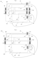
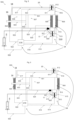
- Figs. 1 to 8 show a first to an eight embodiment of a hydraulic actuator 100, 200, 300, 400, 500, 600, 700, 800, especially for an aircraft.
- the hydraulic actuator comprises a housing 101, 201, 301, 401, 501, 601, 701, 801 surrounding a cavity, a piston 102, 202, 302, 402, 502, 602, 702, 802 arranged on a piston rod 103, 203, 303, 403, 503, 603, 703, 803, a first to third pressure chamber 108, 107, 113; 208, 207, 213; 308, 307, 331; 408, 407, 409; 508, 507, 513; 608, 607, 613; 708, 707, 731; 808, 807; 809, a plurality of arrangements of piezoelectric elements 104, 105, 106; 204, 206; 304, 305; 404, 405, 450, 451; 504, 505, 506; 604, 606; 704, 7
- the first chamber 108, 208, 308, 408, 508, 608, 708, 808 and the second chamber 107, 207, 307, 407, 507, 607, 707, 807 are arranged in the cavity and separated by the piston 102, 202, 302, 402, 502, 602, 702, 802.
- the piston 102, 202, 302, 402, 502, 602, 702, 802 is movable along an actuation direction.
- Each of the arrangements is arranged inside one of the first to third chambers 107, 207, 307, 407, 507, 607, 707, 807; 108, 208, 308, 408, 508, 608, 708, 808; 113, 213, 331, 409, 513, 613, 731, 809 and configured to selectively contract or expand in order to change the volume of this chamber 107, 207, 307, 407, 507, 607, 707, 807; 108, 208, 308, 408, 508, 608, 708, 808; 113, 213, 331, 409, 513, 613, 731, 809 occupied by the piezoelectric elements of the arrangement.
- each arrangement of piezoelectric elements 104, 105, 106; 204, 206; 304, 305; 404, 405, 450, 451; 504, 505, 506; 604, 606; 704, 705; 804; 805, 850, 851 includes a piezoelectric stack 16 and a diaphragm 18 or membrane.
- the diaphragm 18 separates the chamber in which the arrangement is arranged into a fluid compartment for hydraulic fluid and a compartment for the piezoelectric stack. By contracting or expanding of the piezoelectric stack, the diaphragm 18 is moved so that the volume of the fluid compartment is changed.
- the plurality of arrangements of piezoelectric elements includes at least a first arrangement of piezoelectric elements 104, 204, 304, 404, 504, 604, 704, 804 and a second arrangement of piezoelectric elements 106, 206, 332, 450-453, 506, 606, 732, 850-853.
- the first arrangement of piezoelectric elements 104, 204, 304, 404, 504, 604, 704, 804 is arranged inside the first chamber 108, 208, 308, 408, 508, 608, 708, 808 and configured to change the volume of the first chamber occupied by the piezoelectric elements of the first arrangement.
- the second arrangement of piezoelectric elements 106, 206, 332, 450-453, 506, 606, 732, 850-853 is arranged inside the third chamber 113, 213, 331, 409, 513, 613, 731, 809 and is configured to change the volume of the third chamber occupied by the piezoelectric elements of the second arrangement.
- the hydraulic actuator hydraulic actuator 100, 200, 300, 400, 500, 600, 700, 800 comprises a computer-implemented internal hydraulic braking means 14.
- the braking means 14 comprises the third chamber 113, 213, 331, 409, 513, 613, 731, 809, a first fluid connection 10 with a first flow control means 112, 212, 340, 341, 460, 461, 512, 612, 740, 741, 860, 861, a second fluid connection 12 with a second flow control means 110; 210; 342, 343; 462, 463; 510; 610; 742, 743; 862, 863, and a computing means.
- the braking means 14 is configured for a selectively switching between a braking mode and a non-braking mode, wherein in the braking mode the braking means brakes movement of the piston 102, 202, 302, 402, 502, 602, 702, 802 and in the non-braking mode does not brake movement of the piston.
- the first fluid connection 10 connects the third chamber 113, 213, 331, 409, 513, 613, 731, 809 and the first chamber 108, 208, 308, 408, 508, 608, 708, 808.
- the first flow control means 112, 212, 340, 341, 460, 461, 512, 612, 740, 741, 860, 861 is configured to selectively varying flow of a hydraulic fluid through the first fluid connection 10.
- the second fluid connection 12 connects the third chamber 113, 213, 331, 409, 513, 613, 731, 809 and the second chamber 107, 207, 307, 407, 507, 607, 707, 807.
- the second flow control means 110; 210; 342, 343; 462, 463; 510; 610; 742, 743; 862, 863 is configured to selectively vary the flow of hydraulic fluid through the second fluid connection 12.
- the first and second flow control means 112, 212, 340, 341, 460, 461, 512, 612, 740, 741, 860, 861; 110; 210; 342, 343; 462, 463; 510; 610; 742, 743; 862, 863 are selected from a group consisting of valves, active MEMS valves, active disc valves, active one-way disc valves, and magnetorheological valves.
- the flow control means are MEMs valves.
- the computing means is a part, such as a part of a computer program, of the control unit 170, 270, 370, 470, 570, 670, 770, 870.
- the computing means is configured to control the flow control means in order to selectively switch between the braking mode and the non-braking mode.
- the plurality of arrangements of piezoelectric elements includes a third arrangement of piezoelectric elements 105, 305, 405, 505, 704, 804 arranged inside the second chamber 107, 307, 407, 507, 707, 807 and configured to change the volume of the second chamber occupied by the piezoelectric elements of the third arrangement.
- these third arrangement of piezoelectric elements may be omitted.
- Fig. 1 to 8 eight embodiments of the actuator 100, 200, 300, 400, 500, 600, 700, 800 are shown each comprising a third chamber, flow control means, especially valves, and piezo configurations that provide a less complex and compact design of a hydraulic actuator which may be operated without an outer hydraulic system.
- the arrangements of piezoelectric elements comprise piezo stacks.
- a neutral position of the piezo stack is the power off position, and therefore determines the start and end position of the piezo stack.
- the actuator 100 comprises the housing 101, the piston rod 103 and the piston 102, which divides the housing 101 and the hydraulic fluid in the first chamber 108 and the second chamber 107. Also, there is the third chamber 113.
- the third chamber 113 is located at an end of the housing 101, axially adjacent to the second chamber 107.
- the first fluid connection 10 comprises a first valve block 109 including a first valve 110 - in form of a MEMs valve - as first flow control means and a first pipe 114 connecting the first valve block 109 with the second chambers 107 and a further first pipe 115 connecting the valve block 109 with the third chamber 113.
- the second fluid connection 12 comprises a second valve block 111 including a second valve 112 - in form of a MEMs valve - as second fluid control means and a second pipes 117 connecting the second valve block 111 with the first chambers 108 and a further second pipe 116 connecting the second valve block 11 with the third chamber.
- the control unit 170 commands the first piezoelectrical stack 104 to expand from its neutral position over a first cable 122 (or any other first communication link). Simultaneously, the control unit 170 opens the second flow control means 110 - so called MEM-valve - in the second valve block 109 over a second cable 119 (or any other second communication link) and commands the second piezoelectrical stack 106 to contract from its neutral position over a third cable 118 (or any other third communication link).
- the piston 102 moves to the right, lessens the second chamber 107 and hydraulic fluid flows from the second chamber 107 over the second pipes 114 and 115 through the open second flow control means 110 to the third chamber 113.
- This step a) implies that the braking means 14 is in the non-braking mode.
- control unit 170 closes the second flow control means 110.
- control unit 170 commands simultaneously the first piezoelectrical stack 104 to contract, the third piezoelectrical stack 106 to expand fully and the first flow control means 112 - MEM-valve - in the first valve block 111 to open over the cables 118, 121 and 122 (or any other communication link). Hydraulic fluid flows now from the third chamber 113 to the first chamber 108 over the first pipes 117 and 116. This step c) implies that the braking means 14 is in the braking mode.
- the control unit 170 closes the first flow means 112.
- first piezoelectric stack 104 expands not from its neutral position, but from its contracted position to its fully expanded position and that the second piezoelectrical stack 106 contracts not from its neutral position, but from its fully expanded position to its fully contracted position.
- the control unit 170 commands the piezoelectrical stack 105 to expand from its neutral position over a fourth cable 120, simultaneously the control unit 170 opens the first flow control means 112 - so-called active MEM-valve - in the first valve block 111 over a fifth cable 121 and commands the second piezoelectrical stack 106 to contract from its neutral position over the third cable 118.
- the piston 102 moves to the left, lessens the first chamber 108 and hydraulic fluid flows from the first chamber 108 over the first pipes 117 and 116 through the open first flow control means 112 to the third chamber 113.
- This step e1) implies that the brake means 14 is in the non-braking mode.
- control unit 170 closes the first flow control means 112.
- control unit 170 commands simultaneously the third piezoelectrical stack 105 to contract, the second piezoelectrical stack 106 to expand fully and the second flow control means 110 -MEM-valve - in the second valve block 109 to open over the cables 119, 121 and 122. Hydraulic fluid flows now from the third chamber 113 to the second chamber 107.
- This step g1) is a further example of a braking mode.
- the control unit 170 closes the second flow control means 110.
- first step e1) again.
- the difference in following first steps e1) is, that the third piezoelectrical stack 105 expands not from its neutral position, but from its contracted position to its fully expanded position and that the second piezoelectrical stack 106 contracts not from its neutral position, but from its fully expanded position to its fully contracted position.
- the piezoelectrical stacks 104 and 106 move from their actual position, extended or retracted, back to their neutral positions, i.e., commanded by the control unit 170.
- the flow control means 110 and 112 are controlled in an appropriate way by the control unit 170, i.e., the flow control means 110 and 112 are closed, after the piezoelectrical stacks 104 and 106 have reached their neutral position.
- Corresponding steps can be conducted when the piston 202, 302, 402, 502, 602, 702, 802 has reached on of its end positions in the second to eighth embodiment.
- the actuator 200 comprises the housing 201, the piston rod 203 and the piston 202, which divides the housing 201 and the hydraulic fluid in the first chamber 208 and the second chamber 207. Also, there is the third chamber 213. As in the first embodiment, the third chamber 213 is located at the end of the housing 201.
- the second embodiment contains only the first and second arrangements of piezoelectric elements - referred to as first piezoelectric stack 204 and second piezoelectric stack 206 in the following.
- the control unit 270 commands the first piezoelectrical stack 204 to expand from its neutral position over cable 222, simultaneously the control unit 270 opens the second flow control means 210 -so-called active MEM-valve - in the second valve block 209 over the cable 219 and commands the second piezoelectrical stack 206 to contract from its neutral position over the cable 218.
- the piston 202 moves to the right, lessens the second chamber 207 and hydraulic fluid flows from the second chamber 207 over the second pipes 214 and 215 through the open second flow control means 210 to the third chamber 213.
- control unit 270 closes the second control means 210.
- control unit 270 commands simultaneously the first piezoelectrical stack 204 to contract, the second piezoelectrical stack 206 to expand fully and the first flow control means 212 - MEM-valve - in the first valve block 211 to open over the cables 218, 221 and 222. Hydraulic fluid flows now from the third chamber 213 to the first chamber 270 over the first pipes 217 and 216.
- the control unit 270 closes the first flow control means 212.
- the control unit 270 commands the first piezoelectrical stack 204 to contract from its neutral position over cable 222, simultaneously the control unit 270 opens the second flow control means 210 - active MEM-valve - in the second valve block 209 over the cable 219 and commands the second piezoelectrical stack 206 to expand from its neutral position over cable 218.
- the piston 202 moves to the left, lessens the first chamber 208 and hydraulic fluid flows from the third chamber 213 over the second pipes 215 and 214 through the open second flow control means 210 to the second chamber 207. This also implies that the braking means is switched in the non-braking mode.
- control unit 270 closes the second flow control means 210.
- control unit 270 commands simultaneously the first piezoelectrical stack 204 to expand fully, the second piezoelectrical stack 206 to contract fully and the first flow control means 212 - MEM-valve - in the first valve block 211 to open over the cables 222, 221 and 218. Hydraulic fluid flows now from the first chamber 208 to the third chamber 213 through the first pipes 217 and 216. This also implies that the braking means 14 is switched in the braking mode.
- the control unit 270 closes the first flow control means 212.
- first piezoelectrical stack 204 contracts not from its neutral position, but from its expanded position to its fully contracted position and that the second piezoelectrical stack 206 expands not from its neutral position, but from its fully contracted position to its fully contracted position.
- the actuator 300 compromises the housing 301, the piston rod 303 and the piston 302, which divides the housing 301 and the hydraulic fluid in the first chamber 308 and the second chamber 307. Also, there is the third chamber 331, in difference to the first and second embodiments of Figs. 1 and 2 not behind second chamber 307, but around the housing 301 as a hollow cylinder 330.
- the valve blocks 109 and 111 are not needed, because the first flow control means 340, 341 and the second flow control means 342, 343 - here in the form of MEM-valves - can be integrated in the housing 301.
- the first and second fluid connections 10, 12 are in the form of fluid passages in a wall between the housing 301 and the hollow cylinder 330 that can be opened and closed by the flow control means 340-343.
- the control unit 370 commands the first piezoelectrical stack 304 to expand from its neutral position over cable 322, simultaneously the control unit 370 opens the second flow control means 342, 343 - so-called active MEM-valves - in housing 301 over the cable 334 and 336 and commands the second piezoelectrical stack 332 to contract from its neutral position over the cable 333.
- the piston 302 moves to the right, lessens the second chamber 307 and hydraulic fluid flows from the second chamber 307 through the open second flow control means 342 and 343 to the third chamber 331.
- control unit 370 closes the second flow control means 342 and 343.
- control unit 370 commands simultaneously the first piezoelectrical stack 304 to contract, the second piezoelectrical stack 332 to expand fully and the first flow control means 340 and 341 - MEM-valves - in the housing 301 to open over the cables 333, 335 and 336 and 322.
- Hydraulic fluid flows now from the third chamber 331 to the first chamber 308 over the first flow control means 341 and 340.
- the control unit 370 closes the first flow control means 340 and 341.
- first piezoelectrical stack 304 expands not from its neutral position, but from its contracted position to its fully expanded position and that the second piezoelectrical stack 332 contracts not from its neutral position, but from its fully expanded position to its fully contracted position.
- the fluid connections 10, 12 are formed as passages between the hollow piston 402 and the first and second chambers 408, 407 wherein these passages can be closed by flow control means 461-463 formed as active MEM-valves integrated in the piston 402.
- the second arrangement of piezoelectric elements includes piezoelectrical stacks 450-453 in the hollow piston 402.
- the control unit 470 closes the first flow control means 460 and 461.
- first piezoelectrical stack 404 expands not from its neutral position, but from its contracted position to its fully expanded position and that the second piezoelectrical stacks 450, 451, 452 and 453 contract not from their neutral position, but from their fully expanded position to their fully contracted position.
- the control unit 470 commands the third piezoelectrical stack 405 to expand from its neutral position over cable 420, simultaneously the control unit 470 opens the first flow control means 460, 461 - so-called active MEM-valves - in the piston 402 over a not shown cable and commands the second piezoelectrical stacks 450, 451, 452 and/or 453 to contract from their neutral position over the cables 423 and 424.
- the piston 402 moves to the left, lessens the first chamber 408 and hydraulic fluid flows from the first chamber 408 through the open first flow control means 460 and 461 to the third chamber 409.
- control unit 470 closes the first flow control means 460 and 461.
- control unit 470 commands simultaneously the third piezoelectrical stack 405 to contract, the second piezoelectrical stacks 450, 451, 452 and/or 453 to expand fully and the second flow control means 462 and 463 - MEM-valves - in the piston 402 to open over the cables 420, 423 and 424. Hydraulic fluid flows now from the third chamber 409 to the second chamber 407.
- the control unit 470 closes the second flow control means 462 and 463.
- first step e1) again.
- the difference in following first steps a1) is, that the third piezoelectrical stack 405 expands not from its neutral position, but from its contracted position to its fully expanded position and that the piezoelectrical stacks 450, 451, 452 and/or 453 contract not from their neutral position, but from their fully expanded position to their fully contracted position.
- FIG. 5 is very similar to Figures 1, 2 , 3 and 4 .
- the fifth embodiment of Fig. 5 is very similar to the first embodiment of Fig. 1 ;
- the sixth embodiment of Fig. 6 is very similar to the second embodiment of Fig. 2 ;
- the seventh embodiment of Fig. 7 is very similar to the third embodiment of Fig. 3 ;
- the eighth embodiment of Fig. 8 is very similar to the fourth embodiment of Fig. 4 .
- the piston rods 503, 603, 703 and 803 of the fifth to eighth embodiment do not extend into the second chambers 507, 607, 707, 807. So, a hydraulic fluid reservoir 189 is needed.
- the reservoir 189 of the fifth to eighth embodiments is the same as this of Fig. 11 of EP3324055B1 and is also known from US2007/0129681 A1 .
- the reservoir 189 can be controlled by the control unit 570, 670, 770, 870 via a cable 526, 626, 723, 819
- the fluid reservoir 189 is connected via a pipe 523, 623, 823 and a third flow control means, especially a third valve 521, 621, 821 to the second chamber 507, 607, 807.
- the third valve 521, 621, 821 can be controlled by the control unit 570, 670, 870 via a cable 525, 625, 824.
- the fluid reservoir 189 is connected via a pipe 721 and a third flow control means, especially a third valve 720 to the second chamber 707.
- the third valve 720 can be controlled by the control unit 770 via a not shown cable.
- the actuator 500 comprises the housing 501, the piston rod 503 and the piston 502, which divides the housing 505 and the hydraulic fluid in the first chamber 508 and the second chamber 507. Also, there is the third chamber 513.
- the third chamber 513 is located at an end of the housing 501, axially adjacent to the second chamber 507.
- the first fluid connection 10 comprises a first valve block 509 including a first valve 510 - in form of a MEMs valve - as first flow control means and a first pipe 514 connecting the first valve block 509 with the second chambers 507 and a further first pipe 515 connecting the valve block 509 with the third chamber 513.
- the second fluid connection 12 comprises a second valve block 511 including a second valve 512 - in form of a MEMs valve - as second fluid control means and a second pipes 517 connecting the second valve block 511 with the first chambers 508 and a further second pipe 516 connecting the second valve block 511 with the third chamber.
- the control unit 570 commands the first piezoelectrical stack 504 to expand from its neutral position over a first cable 522 (or any other first communication link). Simultaneously, the control unit 570 opens the second flow control means 510 - so called MEM-valve - in the second valve block 509 over a second cable 519 (or any other second communication link) and commands the second piezoelectrical stack 506 to contract from its neutral position over a third cable 518 (or any other third communication link) and the reservoir 189 to expand a step size over cable 526 (or over another communication link) and to open the third valve 521 - MEM-valve - over cable 525 (example for communication link).
- the piston 502 moves to the right, lessens the second chamber 507 and hydraulic fluid flows from the second chamber 507 over the second pipes 514 and 515 through the open second flow control means 510 to the third chamber 513 and through the pipe 523 to the reservoir 189.
- This step a) implies that the braking means 14 is in the non-braking mode.
- control unit 770 closes the second flow control means 742 and 743 and the third valve 720.
- Hydraulic fluid flows now from the third chamber 731 to the first chamber 708 over the first flow control means 741 and 740.
- the control unit 770 closes the first flow control means 740 and 741.
- first step a) again.
- the difference in following first steps a) is, that the first piezoelectrical stack 704 expands not from its neutral position, but from its contracted position to its fully expanded position and that the second piezoelectrical stack 732 contracts not from its neutral position, but from its fully expanded position to its fully contracted position.
- the step size of the reservoir 189 has to be doubled for the first step a).
- the control unit 770 commands the third piezoelectrical stack 705 to expand from its neutral position over cable 719, simultaneously the control unit 770 opens the first flow control means 740, 741 - so-called active MEM-valves - in the housing 701 over the cables 761 and 762 and commands the second piezoelectrical stack 732 to contract from its neutral position over cable 733.
- the piston 702 moves to the left, lessens the first chamber 708 and hydraulic fluid flows from the first chamber 708 through the open first flow control means 740 and 741 to the third chamber 731.
- control unit 770 closes the first flow control means 740 and 741.
- control unit 770 commands simultaneously the third piezoelectrical stack 705 to contract, the second piezoelectrical stack 732 to expand fully and the second flow control means 742 and 743 - MEM-valves - in the housing 701 to open over the cables 719, 733 and 763 and the valve 720 to open and the reservoir 189 to contract a step size. Hydraulic fluid flows now from the third chamber 731 to the second chamber 707.
- the control unit 770 closes the second flow control means 742 and 743 and the third valve 720.
- first step e1 the difference in following first steps e1) is, that the third piezoelectrical stack 705 expands not from its neutral position, but from its contracted position to its fully expanded position and that the second piezoelectrical stack 732 contracts not from its neutral position, but from its fully expanded position to its fully contracted position.
- the step size of the reservoir 189 has to be doubled.
- the actuator 800 compromises the housing 801, the piston rod 803 and the piston 802, configured as hollow piston 802, which divides the housing 801 and the hydraulic fluid in the first chamber 808 and the second chamber 807. Also, there is the third chamber 809, but here placed in the hollow piston 802, in difference to Figs. 1 and 5 .
- the fluid connections 10, 12 are formed as passages between the hollow piston 802 and the first and second chambers 808, 807 wherein these passages can be closed by flow control means 861-863 formed as active MEM-valves integrated in the piston 802.
- the second arrangement of piezoelectric elements includes piezoelectrical stacks 850-853 in the hollow piston 802.
- the control unit 870 commands the first piezoelectrical stack 804 to expand from its neutral position over cable 820, simultaneously the control unit 870 opens the second flow control means 862, 863 - so-called active MEM-valves - over not shown cables and commands the second piezoelectrical stacks 850, 851, 852 and/or 853 to contract from their neutral position over cable 834 and the reservoir 189 to expand a step size over the cable 819 and to open the third (MEM-)valve 821 over the cable 825.
- the piston 802 moves to the right, lessens the second chamber 807 and hydraulic fluid flows from the second chamber 807 through the open second flow control means 862 and 863 to the third chamber 809 and through the pipe 823 to the reservoir 189.
- control unit 870 closes the second flow control means 862 and 863 and the third valve 821.
- control unit 870 commands simultaneously the first piezoelectrical stack 804 to contract, the second piezoelectrical stacks 850, 851, 852 and/or 853 to expand fully and the first flow control means 860, 861 - MEM-valves - in the piston 802 to open over cables 834, 830 and a not shown cable. Hydraulic fluid flows now from the third chamber 809 to the first chamber 808 over the first control means 860 and 861.
- the control unit 870 closes the first flow control means 860 and 861.
- first piezoelectrical stack 804 expands not from its neutral position, but from its contracted position to its fully expanded position and that the second piezoelectrical stacks 850, 851, 852 and 853 contract not from their neutral position, but from their fully expanded position to their fully contracted position.
- the step size of the reservoir 189 has to be doubled in the first step a).
- the control unit 870 commands the third piezoelectrical stack 805 to expand from its neutral position over cable 825, simultaneously the control unit 870 opens the first flow control means 860, 861 - so-called active MEM-valves - in the piston 802 over a not shown cable and commands the second piezoelectrical stacks 850, 851, 852 and/or 853 to contract from their neutral position over the cable 834.
- the piston 802 moves to the left, lessens the first chamber 808 and hydraulic fluid flows from the first chamber 808 through the open first flow control means 860 and 861 to the third chamber 809.
- control unit 870 closes the first flow control means 860 and 861.
- control unit 870 commands simultaneously the third piezoelectrical stack 805 to contract, the second piezoelectrical stacks 850, 851, 852 and/or 853 to expand fully and the second flow control means 862 and 863 - MEM-valves - in the piston 802 to open over the cables 834, 825 and a not shown cable and to contract the reservoir 189 a step size and to open valve 821 over the cable 824. Hydraulic fluid flows now from the third chamber 809 and the reservoir 189 to the second chamber 807.
- the control unit 870 closes the second flow control means 862 and 863.
- first step e1) again.
- the difference in following first steps a1) is, that the third piezoelectrical stack 805 expands not from its neutral position, but from its contracted position to its fully expanded position and that the piezoelectrical stacks 850, 851, 852 and/or 853 contract not from their neutral position, but from their fully expanded position to their fully contracted position.
- the step size of the reservoir 189 in the third step g1 has to be doubled.
- the invention provides a hydraulic actuator (100, 200, 300, 400, 500, 600, 700, 800) comprising a housing (101, 201, 301, 401, 501, 601, 701, 801), a piston (102, 202, 302, 402, 502, 602, 702, 802), first to third pressure chambers (107, 207, 307, 407, 507, 607, 707, 807; 108, 208, 308, 408, 508, 608, 708, 808; 113, 213, 331, 409, 513, 613, 731, 809), and a plurality of arrangements of piezoelectric elements (104, 105, 106; 204, 206; 304, 305; 404, 405, 450, 451; 504, 505, 506; 604, 606; 704, 705; 804; 805, 850, 851) arranged inside one of the plurality of chambers (107, 207, 307, 40
- a computer implemented internal braking means (14) for selectively switching between a braking mode and a non-braking mode of the piston comprises the third chamber (113, 213, 331, 409, 513, 613, 731, 809), and fluid connections (10, 12) between the first to third chambers with flow control means (112, 212, 340, 341, 460, 461, 512, 612, 740, 741, 860, 861; 110; 210; 342, 343; 462, 463; 510; 610; 742, 743; 862, 863).
- FIG. 1 Further embodiments include all meaningful combinations of the components in figures 1 to 8 .
- the third chambers are divided in sub-chambers. In case of such a division there are a plurality of third chambers.
- Embodiments of the hydraulic actuators can be used for the same purposes and with similar functionality as this is disclosed in EP 3 324 055 B1 .
Landscapes
- Engineering & Computer Science (AREA)
- Mechanical Engineering (AREA)
- Physics & Mathematics (AREA)
- Fluid Mechanics (AREA)
- General Engineering & Computer Science (AREA)
- Aviation & Aerospace Engineering (AREA)
- Chemical & Material Sciences (AREA)
- Analytical Chemistry (AREA)
- Actuator (AREA)
- Braking Arrangements (AREA)
Abstract
In order to provide a less complex and more reliable actuator, especially for aircrafts, the invention provides a hydraulic actuator (100, 200, 300, 400, 500, 600, 700, 800) comprising a housing (101, 201, 301, 401, 501, 601, 701, 801), a piston (102, 202, 302, 402, 502, 602, 702, 802), first to third pressure chambers (107, 207, 307, 407, 507, 607, 707, 807; 108, 208, 308, 408, 508, 608, 708, 808; 113, 213, 331, 409, 513, 613, 731, 809), and a plurality of arrangements of piezoelectric elements (104, 105, 106; 204, 206; 304, 305; 404, 405, 450, 451; 504, 505, 506; 604, 606; 704, 705; 804; 805, 850, 851) arranged inside one of the plurality of chambers (107, 207, 307, 407, 507, 607, 707, 807; 108, 208, 308, 408, 508, 608, 708, 808; 113, 213, 331, 409, 513, 613, 731, 809) . A computer implemented internal braking means (14) for selectively switching between a braking mode and a non-braking mode of the piston comprises the third chamber (113, 213, 331, 409, 513, 613, 731, 809), and fluid connections (10, 12) between the first to third chambers with flow control means (112, 212, 340, 341, 460, 461, 512, 612, 740, 741, 860, 861; 110; 210; 342, 343; 462, 463; 510; 610; 742, 743; 862, 863).
Description
- The invention relates to a hydraulic actuator having the features of the preamble of the enclosed claim 1. Further, the invention relates to an operation method for such a hydraulic operator.
- A hydraulic actuator having the features of the preamble of claim 1 is known from
EP 3 324 055 B1 which discloses a hydraulic actuator with an integrated piezo stack powered hydraulic pump. The known actuator comprises a piston supported on a piston rod that extends into the housing of the actuator. The piston forms two hydraulic chambers within the actuator housing. The volume of each chamber is changed by the operation of an associated piezo stack per chamber and a set of valves that selectively enable fluid flow between first and second chambers. An external mechanical brake is also provided at the end of the piston rod to brake its position. A controller controls the operation of the stacks and valves in order to achieve a pumping cycle that results in controlled movement of the piston in the actuator housing. - An object of the invention is to improve such a hydraulic actuator with regard to a reduced complexity, a higher reliability and a compact design.
- For achieving such object, the invention provides a hydraulic actuator according to claim 1. An operating method for such a hydraulic actuator is indicated in the further independent claim.
- Advantageous embodiments are subject-matters of the dependent claims.
- The invention provides according to a first aspect thereof a hydraulic actuator comprising a housing, a piston, a plurality of pressure chambers, a plurality of arrangements of piezoelectric elements, and a braking means. The housing surrounds a cavity. The piston is arranged on a piston rod and is movable within the cavity along an actuation direction. Each of the arrangements of piezoelectric elements is arranged inside one of the plurality of chambers and is configured to selectively contract or expand in order to change the volume of this chamber occupied by the piezoelectric elements of the arrangement. The braking means is configured for a selectively switching between a braking mode and a non-braking mode. In the braking mode, the braking means brakes movement of the piston. In the non-braking mode, the braking means does not brake movement of the piston. The plurality of pressure chambers includes a first chamber and a second chamber separated by the piston. The plurality of arrangements of piezoelectric elements includes a first arrangement of piezoelectric elements arranged inside the first chamber and configured to change the volume of the first chamber occupied by the piezoelectric elements of the first arrangement. The plurality of arrangements of piezoelectric elements further includes a second arrangement of piezoelectric elements. The braking means comprises a third chamber, a first fluid connection with a first flow control means and a second fluid connection with a second flow control means. The first fluid connection connects the third chamber and the first chamber, and the first flow control means is configured to selectively varying flow of a hydraulic fluid through the first fluid connection. The second fluid connection connects the third chamber and the second chamber, and the second flow control means is configured to selectively vary the flow of hydraulic fluid through the second fluid connection. The second arrangement of piezoelectric elements is arranged inside the third chamber and is configured to change the volume of the third chamber occupied by the piezoelectric elements of the second arrangement.
- In some embodiments the plurality of arrangements of piezoelectric elements includes a third arrangement of piezoelectric elements arranged inside the second chamber and configured to change the volume of the second chamber occupied by the piezoelectric elements of the third arrangement.
- In some embodiments a diaphragm or membrane is arranged in at least one of the chambers containing an arrangement of piezoelectric elements. The diaphragm or membrane separates the arrangement of piezoelectric elements (such as a piezo stack) from a hydraulic fluid part of the chamber which can be filled with a hydraulic fluid.
- In some embodiments, the third chamber is arranged at an axial end of the housing adjacent to one of the first and second chambers.
- In some embodiments, the third chamber is arranged radially adjacent to the cavity.
- In some embodiments, the third chamber is arranged around the cavity.
- In some embodiments, the third chamber is arranged inside the piston which is then a hollow piston.
- In some embodiments, the flow control means are selected from a group consisting of valves, active MEMS valves, active disc valves, active one-way disc valves, and magnetorheological valves.
- In some embodiments, the first fluid connection comprises a first valve block including at least one first valve as flow control means and at least one first pipe connecting the first valve block with one of the first and third chambers. Another orifice of the valve block can be directly or indirectly connected to the other of the first and third chambers. Optionally, another first pipe connects the first valve block with the other of the first and third chambers.
- In some embodiments, the second fluid connection comprises a second valve block including at least one second valve as flow control means and at least one second pipe connecting the second valve block with one of the second and third chambers. Another orifice of the valve block can be directly or optionally indirectly connected to the other of the second and third chambers. Optionally, another second pipe connects the second valve block with the other of the second and third chambers.
- In some embodiments, the first fluid connection comprises a first passage in a wall between the first and third chambers. The first passage contains or is formed at least one first valve.
- In some embodiments, the second fluid connection comprises a second passage in a wall between the second and third chambers. The second passage contains or is formed at least one second valve.
- In some embodiments, the hydraulic actuator further includes a hydraulic fluid reservoir connected to at least the one of the first to third chambers such that hydraulic fluid can flow from the hydraulic fluid reservoir to the chamber or from the chamber to the hydraulic fluid reservoir.
- In some embodiments, the hydraulic actuator comprises an electronic control unit configured to control the plurality of arrangements of piezoelectric elements and the first and second flow control means of the braking means. The control unit can be implemented in hardware and/or software. Especially, the control unit comprises a processor and a memory containing a computer program.
- In some embodiments, the control unit is configured to command the arrangements of piezoelectric elements and the flow control means to conduct a first operation in order to move the piston in a first actuation direction.
- In some embodiments, the first operation has the following sequence of steps a) to d):
- a) while the first flow control means is closed, opening the second flow control means, expanding the first arrangement of piezoelectric elements and contracting the second arrangement of piezoelectric elements so that the piston moves in direction to the second chamber, the volume of the second chamber is decreased and hydraulic fluid flows from the second chamber via the second fluid connection to the third chamber;
- b) closing the second flow control means;
- c) opening the first flow control means, contracting the first arrangement of piezoelectric elements, and expanding the second arrangement of piezoelectric elements so that hydraulic fluid flows from the third chamber via the first fluid connection to the first chamber and the movement of the piston is braked;
- d) closing the first flow control means.
- In some embodiments, the control unit is configured to command the arrangements of piezoelectric elements and the flow control means to repeat the first operation, i.e., the sequence of steps a) to d), one or several times. Thus, the piston is moved over a longer distance in the first actuating direction.
- In some embodiments, the control unit is configured to command the arrangements of piezoelectric elements and the flow control means to conduct a second operation in order to move the piston in a second actuation direction which is directed opposite to the first actuation direction.
- According to some embodiments, the second operation has the following sequence of steps e1) to h1):
- e1) while the second flow control means is closed, opening the first flow control means, expanding the third arrangement of piezoelectric elements and contracting the second arrangement of piezoelectric elements so that the piston moves in direction to the first chamber, the volume of the first chamber is decreased and hydraulic fluid flows from the first chamber via the first fluid connection to the third chamber;
- f1) closing the first flow control means;
- g1) opening the second flow control means, contracting the third arrangement of piezoelectric elements, and expanding the second arrangement of piezoelectric elements so that hydraulic fluid flows from the third chamber via the first fluid connection to the first chamber while movement of the piston is braked;
- h1) closing the second flow control means.
- In some embodiments, the second operation has the following sequence of steps e2) to h2):
- e2) while the first flow control means is closed, opening the second flow control means, contracting the first arrangement of piezoelectric elements and expanding the second arrangement of piezoelectric elements so that the piston moves in direction to the first chamber, the volume of the first chamber is decreased and hydraulic fluid flows from the third chamber via the second fluid connection to the second chamber;
- f2) closing the second flow control means;
- g2) opening the first flow control means, expanding the first arrangement of piezoelectric elements, and contracting the second arrangement of piezoelectric elements so that hydraulic fluid flows from the first chamber via the first fluid connection to the third chamber and the movement of the piston is braked;
- h2) closing the first flow control means.
- In some embodiments, the control unit is configured to command the arrangements of piezoelectric elements and the flow control means to repeat the second operation, i.e., the sequence of steps e1) to h1 or e2) to h2), one or several times. Thus, the piston is moved over a longer distance in the second actuating direction.
- In some embodiments, the first to third chambers and the first and second fluid connection, and optionally the fluid reservoir, form a closed hydraulic fluid volume.
- According to another aspect, the invention provides an operation method for automatic operating a hydraulic actuator according to any of the aforementioned embodiments, wherein the operation method comprises the following sequence of steps:
- a) while the first flow control means is closed, opening the second flow control means, expanding the first arrangement of piezoelectric elements and contracting the second arrangement of piezoelectric elements so that the piston moves in direction to the second chamber, the volume of the second chamber is decreased and hydraulic fluid flows from the second chamber via the second fluid connection to the third chamber;
- b) closing the second flow control means;
- c) opening the first flow control means, contracting the first arrangement of piezoelectric elements, and expanding the second arrangement of piezoelectric elements so that hydraulic fluid flows from the third chamber via the first fluid connection to the first chamber and the movement of the piston is braked;
- d) closing the first flow control means.
- As mentioned above, the sequence of steps a) to d) correspond to a first operation mode for moving the piston in the first actuation direction.
- In some embodiments, the operation method further comprises the sequence of steps e1) to h1) or the sequence of steps e2) to h2) as mentioned above. These sequences of steps form a first and second alternative of a second operation mode for moving the piston in the second actuation direction.
- In some embodiments, the sequence of steps a) to d) is repeated one or several times for moving the piston in the first actuation direction.
- In some embodiments, the sequence of steps e1) to h1) or the sequence of steps e2) to h2) are repeated one or several times for moving the piston in the second actuation direction.
- According to another aspect, the invention provides a control unit for a hydraulic actuator according to one of the aforementioned embodiments. The control unit is configured to command the arrangements of piezoelectric elements and the flow control means to conduct the first operation as mentioned above in order to move the piston in a first actuation direction. In some embodiments, the control unit is configured to command the arrangements of piezoelectric elements and the flow control means to conduct the second operation in at least one of its alternatives as mentioned above in order to move the piston in a first actuation direction.
- According to another aspect, the invention provides a computer program comprising instructions to cause the hydraulic actuator according to any of the aforementioned embodiments to execute the steps of the operation method according to any of the aforementioned embodiments.
- Preferred embodiments of the hydraulic actuator are configured for use on an aircraft. For example, the hydraulic actuator may be configured to move an aircraft control surface or an aircraft door or a flap or a part of a landing gear or a fairing.
- According to another aspect, the invention also provides an arrangement comprising a movable part of an aircraft and a hydraulic actuator according to any of the aforementioned embodiments for moving the part. According to another aspect, the invention provides an aircraft comprising a hydraulic actuator according to any of the aforementioned embodiments.
- Preferred embodiments of the invention relate to a hydraulic actuator, especially for an aircraft, with arrangements of piezoelectric actuators without a mechanical brake.
- Preferred embodiments provide an improved actuator. The improved actuator comprises at least two arrangements of piezoelectric elements, e.g., at least two piezo electric stacks, a piston supported on a piston rod, at least three hydraulic chambers within the actuator, and a plurality of flow control means, such as MEMs valves, to direct hydraulic fluid with the chambers and a controller.
- The addition of a third chamber, and a specific configuration of flow control means with a configuration for a specific control methodology provides a selectively operable internal hydraulic brake for the piston.
- This enables removal for the need of an external hydraulic power supply (although an external hydraulic power supply may be included in addition for redundancy or commonality). It also enables the position of the position to be held during the piezo pumping process such that many cycles can be performed when extending or retracting the actuator without the need for an external mechanical brake. Known piezoelectric stacks, particularly for piezoelectric pumps, valves and power electronics that are available on the market can be used, e.g., such as offered by the owner of
US7484940B2 . This reduces development risks, costs and times. - According to preferred embodiments, an external supply of hydraulic pressure to the actuator may be avoided which greatly simplifies the actuator power supply system design. In some embodiments, a hydraulic supply system may be kept to increase the redundancy and commonality for installing the actuator according to preferred embodiments of the invention.
- The hydraulic system may comprise more than one hydraulic cycle due to redundancy reasons. A single hydraulic cycle may alternatively be used without increasing the redundancy of the hydraulic system. Additionally, the hydraulic actuator according to preferred embodiments of the invention can be equipped with an additional conventional brake. So, if there should be any problem with a conventional hydraulic pump of the hydraulic system, at least some of the actuators as suggested here may close their brake and may be used as pumps to supply conventional actuators of the hydraulic system with fluid.
- In preferred embodiments of the invention, the design is
- less complex than the state of art - a mechanical external brake can be avoided
- more reliable - since a mechanical brake is replaced with an internal hydraulic brake operated by fast operating flow control means such as MEMs valves and piezo stacks
- more compact compared to the state of art designs.
- Embodiments of the invention are explained below referring to the accompanying drawings in which:
- Fig. 1
- shows a schematical view of a first embodiment of a hydraulic actuator;
- Fig. 2
- shows a schematical view of a second embodiment of a hydraulic actuator;
- Fig. 3
- shows a schematical view of a third embodiment of a hydraulic actuator;
- Fig. 4
- shows a schematical view of a fourth embodiment of a hydraulic actuator;
- Fig. 5
- shows a schematical view of a fifth embodiment of a hydraulic actuator;
- Fig. 6
- shows a schematical view of a sixth embodiment of a hydraulic actuator;
- Fig. 7
- shows a schematical view of a seventh embodiment of a hydraulic actuator; and
- Fig. 8
- shows a schematical view of an eight embodiment of a hydraulic actuator.
-
Figs. 1 to 8 show a first to an eight embodiment of ahydraulic actuator housing piston piston rod third pressure chamber piezoelectric elements electronic control unit - The
first chamber second chamber piston piston - Each of the arrangements is arranged inside one of the first to
third chambers chamber - In the embodiments shown, each arrangement of
piezoelectric elements piezoelectric stack 16 and adiaphragm 18 or membrane. Thediaphragm 18 separates the chamber in which the arrangement is arranged into a fluid compartment for hydraulic fluid and a compartment for the piezoelectric stack. By contracting or expanding of the piezoelectric stack, thediaphragm 18 is moved so that the volume of the fluid compartment is changed. - The plurality of arrangements of piezoelectric elements includes at least a first arrangement of
piezoelectric elements piezoelectric elements - The first arrangement of
piezoelectric elements first chamber piezoelectric elements third chamber - Further, the hydraulic actuator
hydraulic actuator third chamber first fluid connection 10 with a first flow control means 112, 212, 340, 341, 460, 461, 512, 612, 740, 741, 860, 861, asecond fluid connection 12 with a second flow control means 110; 210; 342, 343; 462, 463; 510; 610; 742, 743; 862, 863, and a computing means. - The braking means 14 is configured for a selectively switching between a braking mode and a non-braking mode, wherein in the braking mode the braking means brakes movement of the
piston - In the embodiments shown, the
first fluid connection 10 connects thethird chamber first chamber first fluid connection 10. - The
second fluid connection 12 connects thethird chamber second chamber second fluid connection 12. - The first and second flow control means 112, 212, 340, 341, 460, 461, 512, 612, 740, 741, 860, 861; 110; 210; 342, 343; 462, 463; 510; 610; 742, 743; 862, 863 are selected from a group consisting of valves, active MEMS valves, active disc valves, active one-way disc valves, and magnetorheological valves. In the embodiments shown, the flow control means are MEMs valves.
- In the embodiments shown, the computing means is a part, such as a part of a computer program, of the
control unit - Referring to
Figs. 1 ,3-5 , and7-8 , the plurality of arrangements of piezoelectric elements includes a third arrangement ofpiezoelectric elements second chamber Figs. 2 and6 , these third arrangement of piezoelectric elements may be omitted. - Referring to the
Fig. 1 to 8 eight embodiments of theactuator - In preferred embodiments, the arrangements of piezoelectric elements comprise piezo stacks. A neutral position of the piezo stack is the power off position, and therefore determines the start and end position of the piezo stack.
- In the following, the first embodiment of the
hydraulic actuator 100 and a preferred operation mode thereof is described in more detail with reference toFig. 1 . - In accordance with
Figure 1 theactuator 100 comprises thehousing 101, thepiston rod 103 and thepiston 102, which divides thehousing 101 and the hydraulic fluid in thefirst chamber 108 and thesecond chamber 107. Also, there is thethird chamber 113. Thethird chamber 113 is located at an end of thehousing 101, axially adjacent to thesecond chamber 107. - The
first fluid connection 10 comprises afirst valve block 109 including a first valve 110 - in form of a MEMs valve - as first flow control means and afirst pipe 114 connecting thefirst valve block 109 with thesecond chambers 107 and a furtherfirst pipe 115 connecting thevalve block 109 with thethird chamber 113. - The
second fluid connection 12 comprises asecond valve block 111 including a second valve 112 - in form of a MEMs valve - as second fluid control means and asecond pipes 117 connecting thesecond valve block 111 with thefirst chambers 108 and a furthersecond pipe 116 connecting the second valve block 11 with the third chamber. - In the following, an operation of the
hydraulic actuator 100 for moving thepiston 102 from the left to the right inFig. 1 - example for first actuation direction - is described. - At the start, all flow control means 110, 112 are closed and all the arrangements of
piezoelectric elements piezoelectrical stacks - To move the
piston 102 from the left to the right inFig. 1 , thecontrol unit 170 commands the firstpiezoelectrical stack 104 to expand from its neutral position over a first cable 122 (or any other first communication link). Simultaneously, thecontrol unit 170 opens the second flow control means 110 - so called MEM-valve - in thesecond valve block 109 over a second cable 119 (or any other second communication link) and commands the secondpiezoelectrical stack 106 to contract from its neutral position over a third cable 118 (or any other third communication link). Thepiston 102 moves to the right, lessens thesecond chamber 107 and hydraulic fluid flows from thesecond chamber 107 over thesecond pipes third chamber 113. This step a) implies that the braking means 14 is in the non-braking mode. - In the next step the
control unit 170 closes the second flow control means 110. - Then the
control unit 170 commands simultaneously the firstpiezoelectrical stack 104 to contract, the thirdpiezoelectrical stack 106 to expand fully and the first flow control means 112 - MEM-valve - in thefirst valve block 111 to open over thecables third chamber 113 to thefirst chamber 108 over thefirst pipes - The
control unit 170 closes the first flow means 112. - Now it begins with the first step a) again. The difference in following first steps a) is, that the first
piezoelectric stack 104 expands not from its neutral position, but from its contracted position to its fully expanded position and that the secondpiezoelectrical stack 106 contracts not from its neutral position, but from its fully expanded position to its fully contracted position. - In the following, an operation of the
hydraulic actuator 100 for moving thepiston 102 from the right to the left inFig. 1 - example for second actuation direction - is described. - At the start, all flow control means 110, 112 are closed and all the arrangements of
piezoelectric elements piezoelectrical stacks - To move the
piston 102 from the right to the left inFig. 1 , thecontrol unit 170 commands thepiezoelectrical stack 105 to expand from its neutral position over afourth cable 120, simultaneously thecontrol unit 170 opens the first flow control means 112 - so-called active MEM-valve - in thefirst valve block 111 over afifth cable 121 and commands the secondpiezoelectrical stack 106 to contract from its neutral position over thethird cable 118. Thepiston 102 moves to the left, lessens thefirst chamber 108 and hydraulic fluid flows from thefirst chamber 108 over thefirst pipes third chamber 113. This step e1) implies that the brake means 14 is in the non-braking mode. - In the next step the
control unit 170 closes the first flow control means 112. - Then the
control unit 170 commands simultaneously the thirdpiezoelectrical stack 105 to contract, the secondpiezoelectrical stack 106 to expand fully and the second flow control means 110 -MEM-valve - in thesecond valve block 109 to open over thecables third chamber 113 to thesecond chamber 107. This step g1) is a further example of a braking mode. - The
control unit 170 closes the second flow control means 110. - Now it begins with the first step e1) again. The difference in following first steps e1) is, that the third
piezoelectrical stack 105 expands not from its neutral position, but from its contracted position to its fully expanded position and that the secondpiezoelectrical stack 106 contracts not from its neutral position, but from its fully expanded position to its fully contracted position. - At the end of both operations of moving in the first or second actuation direction, when the
piston 102 has reached its end position, thepiezoelectrical stacks control unit 170. The flow control means 110 and 112 are controlled in an appropriate way by thecontrol unit 170, i.e., the flow control means 110 and 112 are closed, after thepiezoelectrical stacks piston - In the following, the second embodiment of the
hydraulic actuator 200 and a preferred operation mode thereof is described in more detail with reference toFig. 2 . - In accordance with
Figure 2 theactuator 200 comprises thehousing 201, thepiston rod 203 and thepiston 202, which divides thehousing 201 and the hydraulic fluid in thefirst chamber 208 and thesecond chamber 207. Also, there is thethird chamber 213. As in the first embodiment, thethird chamber 213 is located at the end of thehousing 201. The second embodiment contains only the first and second arrangements of piezoelectric elements - referred to as firstpiezoelectric stack 204 and secondpiezoelectric stack 206 in the following. - In the following, an operation of the
hydraulic actuator 200 for moving thepiston 202 from the left to the right inFig. 2 - example for first actuation direction - is described. - At the start, all flow control means 210, 212 are closed (braking mode switched on) and all the
piezoelectrical stacks - To move the
piston 202 from the left to the right inFig. 2 , thecontrol unit 270 commands the firstpiezoelectrical stack 204 to expand from its neutral position overcable 222, simultaneously thecontrol unit 270 opens the second flow control means 210 -so-called active MEM-valve - in thesecond valve block 209 over thecable 219 and commands the secondpiezoelectrical stack 206 to contract from its neutral position over thecable 218. Thepiston 202 moves to the right, lessens thesecond chamber 207 and hydraulic fluid flows from thesecond chamber 207 over thesecond pipes third chamber 213. - In the next step the
control unit 270 closes the second control means 210. - Then the
control unit 270 commands simultaneously the firstpiezoelectrical stack 204 to contract, the secondpiezoelectrical stack 206 to expand fully and the first flow control means 212 - MEM-valve - in thefirst valve block 211 to open over thecables third chamber 213 to thefirst chamber 270 over thefirst pipes - The
control unit 270 closes the first flow control means 212. - Now it begins with the first step a) again, with the differences as already described above for the first embodiment.
- In the following, an operation of the
hydraulic actuator 200 for moving thepiston 202 from the right to the left inFig. 2 - example for second actuation direction - is described. - At the start, all flow control means 210, 212 are closed and all the
piezoelectrical stacks - To move the
piston 202 from the right to the left thecontrol unit 270 commands the firstpiezoelectrical stack 204 to contract from its neutral position overcable 222, simultaneously thecontrol unit 270 opens the second flow control means 210 - active MEM-valve - in thesecond valve block 209 over thecable 219 and commands the secondpiezoelectrical stack 206 to expand from its neutral position overcable 218. Thepiston 202 moves to the left, lessens thefirst chamber 208 and hydraulic fluid flows from thethird chamber 213 over thesecond pipes second chamber 207. This also implies that the braking means is switched in the non-braking mode. - In the next step the
control unit 270 closes the second flow control means 210. - Then the
control unit 270 commands simultaneously the firstpiezoelectrical stack 204 to expand fully, the secondpiezoelectrical stack 206 to contract fully and the first flow control means 212 - MEM-valve - in thefirst valve block 211 to open over thecables first chamber 208 to thethird chamber 213 through thefirst pipes - The
control unit 270 closes the first flow control means 212. - Now it begins with the first step e2) again. The difference in following first steps e2) is, that the first
piezoelectrical stack 204 contracts not from its neutral position, but from its expanded position to its fully contracted position and that the secondpiezoelectrical stack 206 expands not from its neutral position, but from its fully contracted position to its fully contracted position. - In the following, the third embodiment of the
hydraulic actuator 300 and a preferred operation mode thereof is described in more detail with reference toFig. 3 . - In accordance with
Fig. 3 theactuator 300 compromises thehousing 301, thepiston rod 303 and thepiston 302, which divides thehousing 301 and the hydraulic fluid in thefirst chamber 308 and thesecond chamber 307. Also, there is thethird chamber 331, in difference to the first and second embodiments ofFigs. 1 and 2 not behindsecond chamber 307, but around thehousing 301 as ahollow cylinder 330. The valve blocks 109 and 111 are not needed, because the first flow control means 340, 341 and the second flow control means 342, 343 - here in the form of MEM-valves - can be integrated in thehousing 301. The first andsecond fluid connections housing 301 and thehollow cylinder 330 that can be opened and closed by the flow control means 340-343. - In the following, an operation of the
hydraulic actuator 300 for moving thepiston 302 from the left to the right inFig. 3 - example for first actuation direction - is described. - At the start, all flow control means 340-343 are closed and all the arrangements of
piezoelectric elements piezoelectrical stacks - To move the
piston 302 from the left to the right inFig. 3 thecontrol unit 370 commands the firstpiezoelectrical stack 304 to expand from its neutral position overcable 322, simultaneously thecontrol unit 370 opens the second flow control means 342, 343 - so-called active MEM-valves - inhousing 301 over thecable piezoelectrical stack 332 to contract from its neutral position over thecable 333. Thepiston 302 moves to the right, lessens thesecond chamber 307 and hydraulic fluid flows from thesecond chamber 307 through the open second flow control means 342 and 343 to thethird chamber 331. - In the next step the
control unit 370 closes the second flow control means 342 and 343. - Then the
control unit 370 commands simultaneously the firstpiezoelectrical stack 304 to contract, the secondpiezoelectrical stack 332 to expand fully and the first flow control means 340 and 341 - MEM-valves - in thehousing 301 to open over thecables - Hydraulic fluid flows now from the
third chamber 331 to thefirst chamber 308 over the first flow control means 341 and 340. - The
control unit 370 closes the first flow control means 340 and 341. - Now it begins with the first step a) again. The difference in following first steps a) is, that the first
piezoelectrical stack 304 expands not from its neutral position, but from its contracted position to its fully expanded position and that the secondpiezoelectrical stack 332 contracts not from its neutral position, but from its fully expanded position to its fully contracted position. - In the following, an operation of the
hydraulic actuator 300 for moving thepiston 302 from the right to the left inFig. 3 - example for second actuation direction - is described. - At the start, all flow control means 340-343 are closed and all
piezoelectrical stacks - To move the
piston 302 from the right to the left thecontrol unit 370 commands the thirdpiezoelectrical stack 305 to expand from its neutral position overcable 318, simultaneously thecontrol unit 370 opens the first flow control means 340, 341 - so-called active MEM-valves - in thehousing 301 over thecables piezoelectrical stack 332 to contract from its neutral position overcable 333. Thepiston 302 moves to the left, lessens thefirst chamber 370 and hydraulic fluid flows from thefirst chamber 308 through the open first flow control means 340 and 341 to thethird chamber 331. - In the next step the
control unit 370 closes the first flow control means 340 and 341. - Then the
control unit 370 commands simultaneously the thirdpiezoelectrical stack 305 to contract, the secondpiezoelectrical stack 332 to expand fully and the second flow control means 342 and 343 - MEM-valves - in thehousing 301 to open over thecables third chamber 331 to thesecond chamber 307. - The
control unit 370 closes the second flow control means 342 and 343. - Now it begins with the first step again e1). The difference in following first steps e1) is, that the third
piezoelectrical stack 305 expands not from its neutral position, but from its contracted position to its fully expanded position and that the secondpiezoelectrical stack 332 contracts not from its neutral position, but from its fully expanded position to its fully contracted position. - In the following, the fourth embodiment of the
hydraulic actuator 400 and a preferred operation mode thereof is described in more detail with reference toFig. 4 . - In accordance with
Fig. 4 theactuator 400 compromises thehousing 401, thepiston rod 403 and thepiston 402, configured ashollow piston 402, which divides thehousing 401 and the hydraulic fluid in thefirst chamber 408 and thesecond chamber 407. Also, there is thethird chamber 409, but here placed in thehollow piston 402, in difference toFig. 1 . - The
fluid connections hollow piston 402 and the first andsecond chambers piston 402. The second arrangement of piezoelectric elements includes piezoelectrical stacks 450-453 in thehollow piston 402. - In the following, an operation of the
hydraulic actuator 400 for moving thepiston 402 from the left to the right inFig. 4 - example for first actuation direction - is described. - At the start, all flow control means 460-463 are closed and all the arrangements of
piezoelectric elements 404, 450-453, 405 - referred to as first to thirdpiezoelectrical stacks 404, 450-453, 405 in the following - are in the neutral position. - To move the
hollow piston 402 from the left to the right thecontrol unit 470 commands the firstpiezoelectrical stack 404 to expand from its neutral position overcable 422, simultaneously thecontrol unit 470 opens the second flow control means 462, 463 - so-called active MEM-valves - over not shown cables and commands the secondpiezoelectrical stacks cables piston 402 moves to the right, lessens thesecond chamber 407 and hydraulic fluid flows from thesecond chamber 407 through the open second flow control means 462 and 463 to thethird chamber 409. - In the next step the
control unit 470 closes the second flow control means 462 and 463. - Then the
control unit 470 commands simultaneously the firstpiezoelectrical stack 404 to contract, the secondpiezoelectrical stacks third chamber 409 to thefirst chamber 408. - The
control unit 470 closes the first flow control means 460 and 461. - Now it begins with the first step again a). The difference in following first steps a) is, that the first
piezoelectrical stack 404 expands not from its neutral position, but from its contracted position to its fully expanded position and that the secondpiezoelectrical stacks - In the following, an operation of the
hydraulic actuator 400 for moving thepiston 402 from the right to the left inFig. 4 - example for second actuation direction - is described. - At the start, all flow control means 460-463 are closed and all
piezoelectrical stacks 404, 450-453, 405 are in the neutral position. - To move the
piston 402 from the right to the left thecontrol unit 470 commands the thirdpiezoelectrical stack 405 to expand from its neutral position overcable 420, simultaneously thecontrol unit 470 opens the first flow control means 460, 461 - so-called active MEM-valves - in thepiston 402 over a not shown cable and commands the secondpiezoelectrical stacks cables piston 402 moves to the left, lessens thefirst chamber 408 and hydraulic fluid flows from thefirst chamber 408 through the open first flow control means 460 and 461 to thethird chamber 409. - In the next step the
control unit 470 closes the first flow control means 460 and 461. - Then the
control unit 470 commands simultaneously the thirdpiezoelectrical stack 405 to contract, the secondpiezoelectrical stacks piston 402 to open over thecables third chamber 409 to thesecond chamber 407. - The
control unit 470 closes the second flow control means 462 and 463. - Now it begins with the first step e1) again. The difference in following first steps a1) is, that the third
piezoelectrical stack 405 expands not from its neutral position, but from its contracted position to its fully expanded position and that thepiezoelectrical stacks - In the following, fifth to eighth embodiments of the
hydraulic actuator Figs. 5 to 8 . TheFigures 5, 6 ,7 and8 are similar toFigures 1, 2 ,3 and 4 . Especially, the fifth embodiment ofFig. 5 is very similar to the first embodiment ofFig. 1 ; the sixth embodiment ofFig. 6 is very similar to the second embodiment ofFig. 2 ; the seventh embodiment ofFig. 7 is very similar to the third embodiment ofFig. 3 ; and the eighth embodiment ofFig. 8 is very similar to the fourth embodiment ofFig. 4 . - But in difference to the first to fourth embodiments, the
piston rods second chambers hydraulic fluid reservoir 189 is needed. Thereservoir 189 of the fifth to eighth embodiments is the same as this of Fig. 11 ofEP3324055B1 and is also known fromUS2007/0129681 A1 . Thereservoir 189 can be controlled by thecontrol unit cable fluid reservoir 189 is connected via apipe third valve second chamber third valve control unit cable fluid reservoir 189 is connected via apipe 721 and a third flow control means, especially athird valve 720 to thesecond chamber 707. Thethird valve 720 can be controlled by thecontrol unit 770 via a not shown cable. - In the following, the fifth embodiment of the
hydraulic actuator 500 and a preferred operation mode thereof is described in more detail with reference toFig. 5 . - In accordance with
Figure 5 theactuator 500 comprises thehousing 501, thepiston rod 503 and thepiston 502, which divides thehousing 505 and the hydraulic fluid in thefirst chamber 508 and thesecond chamber 507. Also, there is thethird chamber 513. Thethird chamber 513 is located at an end of thehousing 501, axially adjacent to thesecond chamber 507. - The
first fluid connection 10 comprises afirst valve block 509 including a first valve 510 - in form of a MEMs valve - as first flow control means and afirst pipe 514 connecting thefirst valve block 509 with thesecond chambers 507 and a furtherfirst pipe 515 connecting thevalve block 509 with thethird chamber 513. - The
second fluid connection 12 comprises asecond valve block 511 including a second valve 512 - in form of a MEMs valve - as second fluid control means and asecond pipes 517 connecting thesecond valve block 511 with thefirst chambers 508 and a furthersecond pipe 516 connecting thesecond valve block 511 with the third chamber. - In the following, an operation of the
hydraulic actuator 100 for moving thepiston 502 from the left to the right inFig. 5 - example for first actuation direction - is described. - At the start, all flow control means 510, 512 are closed and all the arrangements of
piezoelectric elements piezoelectrical stacks - To move the
piston 502 from the left to the right inFig. 5 , thecontrol unit 570 commands the firstpiezoelectrical stack 504 to expand from its neutral position over a first cable 522 (or any other first communication link). Simultaneously, thecontrol unit 570 opens the second flow control means 510 - so called MEM-valve - in thesecond valve block 509 over a second cable 519 (or any other second communication link) and commands the secondpiezoelectrical stack 506 to contract from its neutral position over a third cable 518 (or any other third communication link) and thereservoir 189 to expand a step size over cable 526 (or over another communication link) and to open the third valve 521 - MEM-valve - over cable 525 (example for communication link). Thepiston 502 moves to the right, lessens thesecond chamber 507 and hydraulic fluid flows from thesecond chamber 507 over thesecond pipes third chamber 513 and through thepipe 523 to thereservoir 189. This step a) implies that the braking means 14 is in the non-braking mode. - In the next step the
control unit 570 closes the second flow control means 510. - Then the
control unit 570 commands simultaneously the firstpiezoelectrical stack 504 to contract, the thirdpiezoelectrical stack 506 to expand fully and the first flow control means 512 - MEM-valve - in thefirst valve block 511 to open over thecables third chamber 513 to thefirst chamber 508 over thefirst pipes - The
control unit 570 closes the first flow means 512. - Now it begins with the first step a) again. The difference in following first steps a) is, that the first
piezoelectric stack 504 expands not from its neutral position, but from its contracted position to its fully expanded position and that the secondpiezoelectrical stack 506 contracts not from its neutral position, but from its fully expanded position to its fully contracted position. The step size of thereservoir 189 has to be doubled in the first step a). - In the following, an operation of the
hydraulic actuator 500 for moving thepiston 502 from the right to the left inFig. 5 - example for second actuation direction - is described. - At the start, all flow control means 510, 512, 521 are closed and all the arrangements of
piezoelectric elements piezoelectrical stacks - To move the
piston 502 from the right to the left inFig. 5 , thecontrol unit 570 commands thepiezoelectrical stack 505 to expand from its neutral position over a fourth cable 520, simultaneously thecontrol unit 570 opens the first flow control means 512 - so-called active MEM-valve - in thefirst valve block 511 over afifth cable 533 and commands the secondpiezoelectrical stack 506 to contract from its neutral position over thethird cable 518. Thepiston 502 moves to the left, lessens thefirst chamber 508 and hydraulic fluid flows from thefirst chamber 508 over thefirst pipes third chamber 513. This step e1) implies that the brake means 14 is in the non-braking mode. - In the next step the
control unit 570 closes the first flow control means 512. - Then the
control unit 570 commands simultaneously the thirdpiezoelectrical stack 505 to contract, the secondpiezoelectrical stack 506 to expand fully and the second flow control means 510 -MEM-valve - in thesecond valve block 509 to open over thecables third valve 521. Hydraulic fluid flows now from thethird chamber 513 and thereservoir 189 to thesecond chamber 507. This step g1) is a further example of a braking mode. - The
control unit 570 closes the second flow control means 510 and thethird valve 521. - Now it begins with the first step e1) again. The difference in following first steps e1) is, that the third
piezoelectrical stack 505 expands not from its neutral position, but from its contracted position to its fully expanded position and that the secondpiezoelectrical stack 506 contracts not from its neutral position, but from its fully expanded position to its fully contracted position. The step size of thereservoir 189 in the third step g1 has to be doubled. - In the following, the sixth embodiment of the
hydraulic actuator 600 and a preferred operation mode thereof is described in more detail with reference toFig. 6 . - In accordance with
Figure 6 theactuator 600 comprises thehousing 601, thepiston rod 603 and thepiston 602, which divides thehousing 601 and the hydraulic fluid in thefirst chamber 608 and thesecond chamber 607. Also, there is thethird chamber 613. As in the first embodiment, thethird chamber 613 is located at the end of thehousing 601. The second embodiment contains only the first and second arrangements of piezoelectric elements - referred to as firstpiezoelectric stack 604 and secondpiezoelectric stack 606 in the following. - In the following, an operation of the
hydraulic actuator 600 for moving thepiston 606 from the left to the right inFig. 6 - example for first actuation direction - is described. - At the start, all flow control means 610, 612 are closed (braking mode switched on) and all the
piezoelectrical stacks - To move the
piston 602 from the left to the right inFig. 6 , thecontrol unit 670 commands the firstpiezoelectrical stack 604 to expand from its neutral position overcable 622, simultaneously thecontrol unit 670 opens the second flow control means 610 -so-called active MEM-valve - in thesecond valve block 609 over thecable 619 and commands the secondpiezoelectrical stack 606 to contract from its neutral position over thecable 618 and thereservoir 189 to expand a step size over thecable 626 and to open the third (MEM-)valve 621 over thecable 625. Thepiston 602 moves to the right, lessens thesecond chamber 607 and hydraulic fluid flows from thesecond chamber 607 over thesecond pipes third chamber 613 and through thepipe 623 to thereservoir 189. - In the next step the
control unit 670 closes the second control means 610 and thethird valve 621. - Then the
control unit 670 commands simultaneously the firstpiezoelectrical stack 604 to contract, the secondpiezoelectrical stack 606 to expand fully and the first flow control means 612 - MEM-valve - in thefirst valve block 611 to open over thecables third chamber 613 to thefirst chamber 608 over thefirst pipes - The
control unit 670 closes the first flow control means 612. - Now it begins with the first step a) again, with the differences as already described above for the fifth embodiment.
- In the following, an operation of the
hydraulic actuator 600 for moving thepiston 602 from the right to the left inFig. 6 - example for second actuation direction - is described. - At the start, all flow control means 610, 612 are closed and all the
piezoelectrical stacks - To move the
piston 602 from the right to the left thecontrol unit 670 commands the firstpiezoelectrical stack 604 to contract from its neutral position overcable 622, simultaneously thecontrol unit 670 opens the second flow control means 610 - active MEM-valve - in thesecond valve block 609 over thecable 619 and commands the secondpiezoelectrical stack 606 to expand from its neutral position overcable 618 and thereservoir 189 to contract a step size and thethird valve 621 to open. Thepiston 602 moves to the left, lessens thefirst chamber 608 and hydraulic fluid flows from thethird chamber 613 over thesecond pipes second chamber 607. This also implies that the braking means is switched in the non-braking mode. - In the next step the
control unit 670 closes the second flow control means 610 and thethird valve 621. - Then the
control unit 670 commands simultaneously the firstpiezoelectrical stack 604 to expand fully, the secondpiezoelectrical stack 606 to contract fully and the first flow control means 612 - MEM-valve - in thefirst valve block 611 to open over thecables first chamber 608 to thethird chamber 613 through thefirst pipes - The
control unit 670 closes the first flow control means 612. - Now it begins with the first step e2) again. The difference in following first steps e2) is, that the first
piezoelectrical stack 604 contracts not from its neutral position, but from its expanded position to its fully contracted position and that the secondpiezoelectrical stack 606 expands not from its neutral position, but from its fully contracted position to its fully contracted position. The step size of thereservoir 189 has to be doubled in the first step e2). - In the following, the seventh embodiment of the
hydraulic actuator 700 and a preferred operation mode thereof is described in more detail with reference toFig. 7 . - In accordance with
Fig. 7 theactuator 700 compromises thehousing 701, thepiston rod 703 and thepiston 702, which divides thehousing 701 and the hydraulic fluid in thefirst chamber 708 and thesecond chamber 707. Also, there is thethird chamber 731, in difference to the first and second embodiments ofFigs. 1, 2 ,5 and 6 not behindsecond chamber 707, but around thehousing 701 as ahollow cylinder 730. The valve blocks 109 and 111 are not needed, because the first flow control means 740, 741 and the second flow control means 742, 743 - here in the form of MEM-valves - can be integrated in thehousing 701. The first andsecond fluid connections housing 701 and thehollow cylinder 730 that can be opened and closed by the flow control means 740-743. - In the following, an operation of the
hydraulic actuator 700 for moving thepiston 702 from the left to the right inFig. 7 - example for first actuation direction - is described. - At the start, all flow control means 740-743, 720 are closed and all the arrangements of
piezoelectric elements piezoelectrical stacks - To move the
piston 702 from the left to the right inFig. 7 thecontrol unit 770 commands the firstpiezoelectrical stack 704 to expand from its neutral position overcable 722, simultaneously thecontrol unit 770 opens the second flow control means 742, 743 - so-called active MEM-valves - inhousing 701 over thecable 734 and 736 and commands the secondpiezoelectrical stack 732 to contract from its neutral position over thecable 733 and thethird valve 720 to open and thereservoir 189 to expand a step size overcable 723. Thepiston 702 moves to the right, lessens thesecond chamber 707 and hydraulic fluid flows from thesecond chamber 707 through the open second flow control means 742 and 743 to thethird chamber 731. - In the next step the
control unit 770 closes the second flow control means 742 and 743 and thethird valve 720. - Then the
control unit 770 commands simultaneously the firstpiezoelectrical stack 704 to contract, the secondpiezoelectrical stack 732 to expand fully and the first flow control means 740 and 741 - MEM-valves - in thehousing 701 to open over thecables - Hydraulic fluid flows now from the
third chamber 731 to thefirst chamber 708 over the first flow control means 741 and 740. - The
control unit 770 closes the first flow control means 740 and 741. - Now it begins with the first step a) again. The difference in following first steps a) is, that the first
piezoelectrical stack 704 expands not from its neutral position, but from its contracted position to its fully expanded position and that the secondpiezoelectrical stack 732 contracts not from its neutral position, but from its fully expanded position to its fully contracted position. The step size of thereservoir 189 has to be doubled for the first step a). - In the following, an operation of the
hydraulic actuator 700 for moving thepiston 702 from the right to the left inFig. 7 - example for second actuation direction - is described. - At the start, all flow control means 740-743, 720 are closed and all
piezoelectrical stacks - To move the
piston 702 from the right to the left thecontrol unit 770 commands the thirdpiezoelectrical stack 705 to expand from its neutral position overcable 719, simultaneously thecontrol unit 770 opens the first flow control means 740, 741 - so-called active MEM-valves - in thehousing 701 over thecables piezoelectrical stack 732 to contract from its neutral position overcable 733. Thepiston 702 moves to the left, lessens thefirst chamber 708 and hydraulic fluid flows from thefirst chamber 708 through the open first flow control means 740 and 741 to thethird chamber 731. - In the next step the
control unit 770 closes the first flow control means 740 and 741. - Then the
control unit 770 commands simultaneously the thirdpiezoelectrical stack 705 to contract, the secondpiezoelectrical stack 732 to expand fully and the second flow control means 742 and 743 - MEM-valves - in thehousing 701 to open over thecables valve 720 to open and thereservoir 189 to contract a step size. Hydraulic fluid flows now from thethird chamber 731 to thesecond chamber 707. - The
control unit 770 closes the second flow control means 742 and 743 and thethird valve 720. - Now it begins with the first step again e1). The difference in following first steps e1) is, that the third
piezoelectrical stack 705 expands not from its neutral position, but from its contracted position to its fully expanded position and that the secondpiezoelectrical stack 732 contracts not from its neutral position, but from its fully expanded position to its fully contracted position. In the third step g1) the step size of thereservoir 189 has to be doubled. - In the following, the eighth embodiment of the
hydraulic actuator 800 and a preferred operation mode thereof is described in more detail with reference toFig. 8 . - In accordance with
Fig. 8 theactuator 800 compromises thehousing 801, thepiston rod 803 and thepiston 802, configured ashollow piston 802, which divides thehousing 801 and the hydraulic fluid in thefirst chamber 808 and thesecond chamber 807. Also, there is thethird chamber 809, but here placed in thehollow piston 802, in difference toFigs. 1 and5 . - The
fluid connections hollow piston 802 and the first andsecond chambers piston 802. The second arrangement of piezoelectric elements includes piezoelectrical stacks 850-853 in thehollow piston 802. - In the following, an operation of the
hydraulic actuator 800 for moving thepiston 802 from the left to the right inFig. 8 - example for first actuation direction - is described. - At the start, all flow control means 860-863, 821 are closed and all the arrangements of
piezoelectric elements 804, 850-853, 805 - referred to as first to thirdpiezoelectrical stacks 804, 850-853, 805 in the following - are in the neutral position. - To move the
hollow piston 802 from the left to the right thecontrol unit 870 commands the firstpiezoelectrical stack 804 to expand from its neutral position overcable 820, simultaneously thecontrol unit 870 opens the second flow control means 862, 863 - so-called active MEM-valves - over not shown cables and commands the secondpiezoelectrical stacks cable 834 and thereservoir 189 to expand a step size over thecable 819 and to open the third (MEM-)valve 821 over thecable 825. Thepiston 802 moves to the right, lessens thesecond chamber 807 and hydraulic fluid flows from thesecond chamber 807 through the open second flow control means 862 and 863 to thethird chamber 809 and through thepipe 823 to thereservoir 189. - In the next step the
control unit 870 closes the second flow control means 862 and 863 and thethird valve 821. - Then the
control unit 870 commands simultaneously the firstpiezoelectrical stack 804 to contract, the secondpiezoelectrical stacks piston 802 to open overcables 834, 830 and a not shown cable. Hydraulic fluid flows now from thethird chamber 809 to thefirst chamber 808 over the first control means 860 and 861. - The
control unit 870 closes the first flow control means 860 and 861. - Now it begins with the first step again a). The difference in following first steps a) is, that the first
piezoelectrical stack 804 expands not from its neutral position, but from its contracted position to its fully expanded position and that the secondpiezoelectrical stacks reservoir 189 has to be doubled in the first step a). - In the following, an operation of the
hydraulic actuator 800 for moving thepiston 802 from the right to the left inFig. 8 - example for second actuation direction - is described. - At the start, all flow control means 860-863 are closed and all
piezoelectrical stacks 804, 850-853, 805 are in the neutral position. - To move the
piston 802 from the right to the left thecontrol unit 870 commands the thirdpiezoelectrical stack 805 to expand from its neutral position overcable 825, simultaneously thecontrol unit 870 opens the first flow control means 860, 861 - so-called active MEM-valves - in thepiston 802 over a not shown cable and commands the secondpiezoelectrical stacks cable 834. Thepiston 802 moves to the left, lessens thefirst chamber 808 and hydraulic fluid flows from thefirst chamber 808 through the open first flow control means 860 and 861 to thethird chamber 809. - In the next step the
control unit 870 closes the first flow control means 860 and 861. - Then the
control unit 870 commands simultaneously the thirdpiezoelectrical stack 805 to contract, the secondpiezoelectrical stacks piston 802 to open over thecables valve 821 over thecable 824. Hydraulic fluid flows now from thethird chamber 809 and thereservoir 189 to thesecond chamber 807. - The
control unit 870 closes the second flow control means 862 and 863. - Now it begins with the first step e1) again. The difference in following first steps a1) is, that the third
piezoelectrical stack 805 expands not from its neutral position, but from its contracted position to its fully expanded position and that thepiezoelectrical stacks reservoir 189 in the third step g1 has to be doubled. - In order to provide a less complex and more reliable actuator, especially for aircrafts, the invention provides a hydraulic actuator (100, 200, 300, 400, 500, 600, 700, 800) comprising a housing (101, 201, 301, 401, 501, 601, 701, 801), a piston (102, 202, 302, 402, 502, 602, 702, 802), first to third pressure chambers (107, 207, 307, 407, 507, 607, 707, 807; 108, 208, 308, 408, 508, 608, 708, 808; 113, 213, 331, 409, 513, 613, 731, 809), and a plurality of arrangements of piezoelectric elements (104, 105, 106; 204, 206; 304, 305; 404, 405, 450, 451; 504, 505, 506; 604, 606; 704, 705; 804; 805, 850, 851) arranged inside one of the plurality of chambers (107, 207, 307, 407, 507, 607, 707, 807; 108, 208, 308, 408, 508, 608, 708, 808; 113, 213, 331, 409, 513, 613, 731, 809) . A computer implemented internal braking means (14) for selectively switching between a braking mode and a non-braking mode of the piston comprises the third chamber (113, 213, 331, 409, 513, 613, 731, 809), and fluid connections (10, 12) between the first to third chambers with flow control means (112, 212, 340, 341, 460, 461, 512, 612, 740, 741, 860, 861; 110; 210; 342, 343; 462, 463; 510; 610; 742, 743; 862, 863).
- Further embodiments include all meaningful combinations of the components in
figures 1 to 8 . In some embodiments the third chambers are divided in sub-chambers. In case of such a division there are a plurality of third chambers. - Embodiments of the hydraulic actuators can be used for the same purposes and with similar functionality as this is disclosed in
EP 3 324 055 B1 .
Claims (15)
- Hydraulic actuator (100, 200, 300, 400, 500, 600, 700, 800) comprising:a housing (101, 201, 301, 401, 501, 601, 701, 801) surrounding a cavity,a piston (102, 202, 302, 402, 502, 602, 702, 802) arranged on a piston rod (103, 203, 303, 403, 503, 603, 703, 803),a plurality of pressure chambers (107, 207, 307, 407, 507, 607, 707, 807; 108, 208, 308, 408, 508, 608, 708, 808; 113, 213, 331, 409, 513, 613, 731, 809), anda plurality of arrangements of piezoelectric elements (104, 105, 106; 204, 206; 304, 305; 404, 405, 450, 451; 504, 505, 506; 604, 606; 704, 705; 804; 805, 850, 851), each of the arrangements is arranged inside one of the plurality of chambers (107, 207, 307, 407, 507, 607, 707, 807; 108, 208, 308, 408, 508, 608, 708, 808; 113, 213, 331, 409, 513, 613, 731, 809) and configured to selectively contract or expand in order to change the volume of this chamber (107, 207, 307, 407, 507, 607, 707, 807; 108, 208, 308, 408, 508, 608, 708, 808; 113, 213, 331, 409, 513, 613, 731, 809) occupied by the piezoelectric elements of the arrangement; anda braking means (14) configured for a selectively switching between a braking mode and a non-braking mode, wherein in the braking mode the braking means brakes movement of the piston (102, 202, 302, 402, 502, 602, 702, 802) and in the non-braking mode does not brake movement of the piston,wherein the plurality of pressure chambers includes a first chamber (108, 208, 308, 408, 508, 608, 708, 808) and a second chamber (107, 207, 307, 407, 507, 607, 707, 807) separated by the piston (102, 202, 302, 402, 502, 602, 702, 802) that is movable along an actuation direction,wherein the plurality of arrangements of piezoelectric elements includes a first arrangement of piezoelectric elements (104, 204, 304, 404, 504, 604, 704, 804) arranged inside the first chamber (108, 208, 308, 408, 508, 608, 708, 808) and configured to change the volume of the first chamber occupied by the piezoelectric elements of the first arrangement, andwherein the plurality of arrangements of piezoelectric elements includes a second arrangement of piezoelectric elements (106, 206, 332, 450-453, 506, 606, 732, 850-853),characterized in that the braking means (14) comprises a third chamber (113, 213, 331, 409, 513, 613, 731, 809), a first fluid connection (10) with a first flow control means (112, 212, 340, 341, 460, 461, 512, 612, 740, 741, 860, 861) and a second fluid connection (12) with a second flow control means (110; 210; 342, 343; 462, 463; 510; 610; 742, 743; 862, 863);wherein the first fluid connection (10) connects the third chamber (113, 213, 331, 409, 513, 613, 731, 809) and the first chamber (108, 208, 308, 408, 508, 608, 708, 808) and the first flow control means (112, 212, 340, 341, 460, 461, 512, 612, 740, 741, 860, 861) is configured to selectively varying flow of a hydraulic fluid through the first fluid connection (10), andwherein the second fluid connection (12) connects the third chamber (113, 213, 331, 409, 513, 613, 731, 809) and the second chamber (107, 207, 307, 407, 507, 607, 707, 807) and the second flow control means (110; 210; 342, 343; 462, 463; 510; 610; 742, 743; 862, 863) is configured to selectively vary the flow of hydraulic fluid through the second fluid connection (12),wherein the second arrangement of piezoelectric elements (106, 206, 332, 450-453, 506, 606, 732, 850-853) is arranged inside the third chamber (113, 213, 331, 409, 513, 613, 731, 809) and is configured to change the volume of the third chamber occupied by the piezoelectric elements of the second arrangement.
- Hydraulic actuator (100, 300, 400, 500, 700, 800) according to claim 1, characterized in that the plurality of arrangements of piezoelectric elements includes a third arrangement of piezoelectric elements (105, 305, 405, 505, 704, 804) arranged inside the second chamber (107, 307, 407, 507, 707, 807) and configured to change the volume of the second chamber occupied by the piezoelectric elements of the third arrangement.
- Hydraulic actuator (100, 200, 300, 400, 500, 600, 700, 800) according to any of the preceding claims, characterized in that the third chamber is arranged3.1 at one of the axial ends of the housing (100, 200) adjacent to one of the first and second chambers, or3.2 radially adjacent to the cavity, or3.3 around the cavity or3.4 inside the hollow piston (402, 802).
- Hydraulic actuator (100, 200, 300, 400, 500, 600, 700, 800) according to any of the preceding claims, characterized in that the first and/or second fluid connection (10, 12) comprise4.1 a valve block (109, 111; 209, 212; 509, 511; 609, 611) including the valve (110, 112; 210, 212; 510, 512; 610, 612) and pipes (114-117; 214-217; 514-517; 614-617) connecting the valve block with the chambers (113, 108; 113, 107; 213, 208; 213, 207; 513, 508; 513, 507; 613, 608; 613, 607) connected by the fluid connection (10, 12) or4.2 a passage in a wall between the chambers (331, 308; 331, 307; 409, 408; 409, 407; 731, 708; 731, 707; 809, 808; 809, 807) connected by the fluid connection (10, 12) wherein the passage contains or is formed by a valve (340-343; 460-463; 740-743; 860-863).
- Hydraulic actuator (500, 600, 700, 800) according to any of the preceding claims, characterized by a hydraulic fluid reservoir (189) connected to at least the one of the first to third chambers such that hydraulic fluid can flow from the hydraulic fluid reservoir (189) to the chamber or from the chamber to the hydraulic fluid reservoir (189).
- Hydraulic actuator (100, 200, 300, 400, 500, 600, 700, 800) according to any of the preceding claims further comprising an electronic control unit (170, 270, 370, 470, 570, 670, 770, 870) configured to control the plurality of arrangements of piezoelectric elements (104, 105, 106; 204, 206; 304, 305, 332; 404, 405, 450-453; 504, 505, 506; 604, 606; 704, 705, 732; 804; 805, 85-853) and the first and second flow control means (112, 212, 340, 341, 460, 461, 512, 612, 740, 741, 860, 861; 110; 210; 342, 343; 462, 463; 510; 610; 742, 743; 862, 863) of the braking means (14) to conduct a first operation with the following sequence of steps a) to d):a) while the first flow control means (112, 212, 340, 341, 460, 461, 512, 612, 740, 741, 860, 861) is closed, opening the second flow control means (110; 210; 342, 343; 462, 463; 510; 610; 742, 743; 862, 863), expanding the first arrangement of piezoelectric elements (104, 204, 304, 404, 504, 604, 704, 804) and contracting the second arrangement of piezoelectric elements (106, 206, 332, 450-453, 506, 606, 732, 850-853) so that the piston (102, 202, 302, 402, 502, 602, 702, 802) moves in direction to the second chamber (107, 207, 307, 407, 507, 607, 807), the volume of the second chamber is decreased and hydraulic fluid flows from the second chamber via the second fluid connection (12) to the third chamber (113, 213, 331, 409, 513, 613, 731, 809);b) closing the second flow control means (110; 210; 342, 343; 462, 463; 510; 610; 742, 743; 862, 863);c) opening the first flow control means (112, 212, 340, 341, 460, 461, 512, 612, 740, 741, 860, 861), contracting the first arrangement of piezoelectric elements (104, 204, 304, 404, 504, 604, 704, 804), and expanding the second arrangement of piezoelectric elements (106, 206, 332, 450-453, 506, 606, 732, 850-853) so that hydraulic fluid flows from the third chamber (113, 213, 331, 409, 513, 613, 731, 809) via the first fluid connection (10) to the first chamber (108, 208, 308, 408, 508, 608, 708, 808) and the movement of the piston (102, 202, 302, 402, 502, 602, 702, 802) is braked;d) closing the first flow control means (112, 212, 340, 341, 460, 461, 512, 612, 740, 741, 860, 861).
- Hydraulic actuator (100, 200, 300, 400, 500, 600, 700, 800) according to claim 6, wherein the control unit (170, 270, 370, 470, 570, 670, 770, 870) is configured to control the plurality of arrangements of piezoelectric elements (104, 105, 106; 204, 206; 304, 305, 332; 404, 405, 450-453; 504, 505, 506; 604, 606; 704, 705, 732; 804; 805, 850-853) and the first and second flow control means (112, 212, 340, 341, 460, 461, 512, 612, 740, 741, 860, 861; 110; 210; 342, 343; 462, 463; 510; 610; 742, 743; 862, 863) of the braking means (14) such that the first operation is repeated one or several times in order to move the piston in a first actuating direction.
- Hydraulic actuator (100, 300, 400, 500, 700, 800) according to claim 2 and any of the claims 6 or 7, wherein the control unit (170, 370, 470, 570, 770, 870) is configured to further control the plurality of arrangements of piezoelectric elements (104, 105, 106; 304, 305, 332; 404, 405, 450-451; 504, 505, 506; 704, 705, 732; 804, 805, 850-853) and the first and second flow control means (112, 340, 341, 460, 461, 512, 740, 741, 860, 861; 110; 342, 343; 462, 463; 510; 742, 743; 862, 863) of the braking means (14) to conduct a second operation with the following sequence of steps e1) to h1):e1) while the second flow control means (110; 342, 343; 462, 463; 510; 742, 743; 862, 863) is closed, opening the first flow control means (112, 340, 341, 460, 461, 512, 740, 741, 860, 861), expanding the third arrangement of piezoelectric elements (105, 305, 405, 505, 705, 805) and contracting the second arrangement of piezoelectric elements (106, 332, 450-453, 506, 732, 850-853) so that the piston (102, 302, 402, 502, 702, 802) moves in direction to the first chamber (107, 307, 407, 507, 807), the volume of the first chamber is decreased and hydraulic fluid flows from the first chamber via the first fluid connection (10) to the third chamber (113, 331, 409, 513, 731, 809);f1) closing the first flow control means (112, 340, 341, 460, 461, 512, 740, 741, 860, 861);g1) opening the second flow control means (110; 342, 343; 462, 463; 510; 742, 743; 862, 863), contracting the third arrangement of piezoelectric elements (105, 305, 405, 505, 705, 805), and expanding the second arrangement of piezoelectric elements (106, 206, 332, 450-453, 506, 606, 732, 850-853) so that hydraulic fluid flows from the third chamber (113, 213, 331, 409, 513, 613, 731, 809) via the first fluid connection (10) to the first chamber (108, 208, 308, 408, 508, 608, 708, 808) while movement of the piston (102, 202, 302, 402, 502, 602, 702, 802) is braked;h1) closing the second flow control means (110; 342, 343; 462, 463; 510; 742, 743; 862, 863).
- Hydraulic actuator (200, 600) according to any of the claims 6 or claim 7, wherein the control unit (270, 670) is configured to further control the plurality of arrangements of piezoelectric elements (204, 206; 604, 606) and the first and second flow control means (212, 612; 210, 610) of the braking means (14) to conduct a second operation with the following sequence of steps e2) to h2):e2) while the first flow control means (212, 612) is closed, opening the second flow control means (210; 610), contracting the first arrangement of piezoelectric elements (204, 604) and expanding the second arrangement of piezoelectric elements (206, 606) so that the piston (202, 602) moves in direction to the first chamber (208, 608), the volume of the first chamber (208, 608) is decreased and hydraulic fluid flows from the third chamber (213, 613) via the second fluid connection (12) to the second chamber (207, 607);f2) closing the second flow control means (210; 610);g2) opening the first flow control means (212, 612), expanding the first arrangement of piezoelectric elements (204, 604), and contracting the second arrangement of piezoelectric elements (206, 606) so that hydraulic fluid flows from the first chamber (208, 608) via the first fluid connection (10) to the third chamber (213, 613) and the movement of the piston (202, 602) is braked;h2) closing the first flow control means (212, 612).
- Hydraulic actuator (100, 200, 300, 400, 500, 600, 700, 800) according to claim 8 or claim 9, wherein the control unit (170, 270, 370, 470, 570, 670, 770, 870) is configured to control the plurality of arrangements of piezoelectric elements (104, 105, 106; 204, 206; 304, 305, 332; 404, 405, 450-453; 504, 505, 506; 604, 606; 704, 705, 732; 804; 805, 850-853) and the first and second flow control means (112, 212, 340, 341, 460, 461, 512, 612, 740, 741, 860, 861; 110; 210; 342, 343; 462, 463; 510; 610; 742, 743; 862, 863) of the braking means (14) such that the second operation is repeated one or several times in order to move the piston in a second actuating direction.
- Hydraulic actuator (100, 200, 300, 400, 500, 600, 700, 800) according to any of the preceding claims characterized in that the first to third chambers (107, 207, 307, 407, 507, 607, 707, 807; 108, 208, 308, 408, 508, 608, 708, 808; 113, 213, 331, 409, 513, 613, 731, 809) and the first and second fluid connection (10, 12), and optionally the fluid reservoir (189), form a closed volume.
- Operation method for automatic operating a hydraulic actuator (100, 200, 300, 400, 500, 600, 700, 800) according to any of the preceding claims, comprising the following sequence of steps:a) while the first flow control means (112, 212, 340, 341, 460, 461, 512, 612, 740, 741, 860, 861) is closed, opening the second flow control means (110; 210; 342, 343; 462, 463; 510; 610; 742, 743; 862, 863), expanding the first arrangement of piezoelectric elements (104, 204, 304, 404, 504, 604, 704, 804) and contracting the second arrangement of piezoelectric elements (106, 206, 332, 450-453, 506, 606, 732, 850-853) so that the piston (102, 202, 302, 402, 502, 602, 702, 802) moves in direction to the second chamber (107, 207, 307, 407, 507, 607, 807), the volume of the second chamber is decreased and hydraulic fluid flows from the second chamber via the second fluid connection (12) to the third chamber (113, 213, 331, 409, 513, 613, 731, 809);b) closing the second flow control means (110; 210; 342, 343; 462, 463; 510; 610; 742, 743; 862, 863);c) opening the first flow control means (112, 212, 340, 341, 460, 461, 512, 612, 740, 741, 860, 861), contracting the first arrangement of piezoelectric elements (104, 204, 304, 404, 504, 604, 704, 804), and expanding the second arrangement of piezoelectric elements (106, 206, 332, 450-453, 506, 606, 732, 850-853) so that hydraulic fluid flows from the third chamber (113, 213, 331, 409, 513, 613, 731, 809) via the first fluid connection (10) to the first chamber (108, 208, 308, 408, 508, 608, 708, 808) and the movement of the piston (102, 202, 302, 402, 502, 602, 702, 802) is braked;d) closing the first flow control means (112, 212, 340, 341, 460, 461, 512, 612, 740, 741, 860, 861).
- Operation method according to claim 12, for operating a hydraulic actuator according to claim 2 or any of the claims 3 to 11 directly or indirectly dependent from claim 2, further comprising the following sequence of steps:e1) while the second flow control means (110; 342, 343; 462, 463; 510; 742, 743; 862, 863) is closed, opening the first flow control means (112, 340, 341, 460, 461, 512, 740, 741, 860, 861), expanding the third arrangement of piezoelectric elements (105, 305, 405, 505, 705, 805) and contracting the second arrangement of piezoelectric elements (106, 332, 450-453, 506, 732, 850-853) so that the piston (102, 302, 402, 502, 702, 802) moves in direction to the first chamber (107, 307, 407, 507, 807), the volume of the first chamber is decreased and hydraulic fluid flows from the first chamber via the first fluid connection (10) to the third chamber (113, 331, 409, 513, 731, 809);f1) closing the first flow control means (112, 340, 341, 460, 461, 512, 740, 741, 860, 861);g1) opening the second flow control means (110; 342, 343; 462, 463; 510; 742, 743; 862, 863), contracting the third arrangement of piezoelectric elements (105, 305, 405, 505, 705, 805), and expanding the second arrangement of piezoelectric elements (106, 206, 332, 450-453, 506, 606, 732, 850-853) so that hydraulic fluid flows from the third chamber (113, 213, 331, 409, 513, 613, 731, 809) via the first fluid connection (10) to the first chamber (108, 208, 308, 408, 508, 608, 708, 808) while movement of the piston (102, 202, 302, 402, 502, 602, 702, 802) is braked;h1) closing the second flow control means (110; 342, 343; 462, 463; 510; 742, 743; 862, 863).
- Operation method according to claim 12, further comprising the following sequence of steps:e2) while the first flow control means (212, 612) is closed, opening the second flow control means (210; 610), contracting the first arrangement of piezoelectric elements (204, 604) andexpanding the second arrangement of piezoelectric elements (206, 606) so that the piston (202, 602) moves in direction to the first chamber (208, 608), the volume of the first chamber (208, 608) is decreased and hydraulic fluid flows from the third chamber (213, 613) via the second fluid connection (12) to the second chamber (207, 607);f2) closing the second flow control means (210; 610);g2) opening the first flow control means (212, 612), expanding the first arrangement of piezoelectric elements (204, 604), and contracting the second arrangement of piezoelectric elements (206, 606) so that hydraulic fluid flows from the first chamber (208, 608) via the first fluid connection (10) to the third chamber (213, 613) and the movement of the piston (202, 602) is braked;h2) closing the first flow control means (212, 612).
- Operation method according to any the claims 12 to 14 further comprising:
repeating15.1 the sequence of steps a) to d) one or several times for moving the piston in a first actuation direction and/or15.2 the sequence of steps e1) to h1) or e2) to h2) one or several times for moving the piston in a second actuation direction.
Priority Applications (2)
| Application Number | Priority Date | Filing Date | Title |
|---|---|---|---|
| EP23185853.1A EP4495431A1 (en) | 2023-07-17 | 2023-07-17 | Hydraulic actuator and method for operating |
| US18/761,984 US12618420B2 (en) | 2023-07-17 | 2024-07-02 | Hydraulic actuator and method for operating |
Applications Claiming Priority (1)
| Application Number | Priority Date | Filing Date | Title |
|---|---|---|---|
| EP23185853.1A EP4495431A1 (en) | 2023-07-17 | 2023-07-17 | Hydraulic actuator and method for operating |
Publications (1)
| Publication Number | Publication Date |
|---|---|
| EP4495431A1 true EP4495431A1 (en) | 2025-01-22 |
Family
ID=87378002
Family Applications (1)
| Application Number | Title | Priority Date | Filing Date |
|---|---|---|---|
| EP23185853.1A Pending EP4495431A1 (en) | 2023-07-17 | 2023-07-17 | Hydraulic actuator and method for operating |
Country Status (2)
| Country | Link |
|---|---|
| US (1) | US12618420B2 (en) |
| EP (1) | EP4495431A1 (en) |
Citations (4)
| Publication number | Priority date | Publication date | Assignee | Title |
|---|---|---|---|---|
| US20070129681A1 (en) | 2005-11-01 | 2007-06-07 | Par Technologies, Llc | Piezoelectric actuation of piston within dispensing chamber |
| DE102005060436A1 (en) * | 2005-12-15 | 2007-06-21 | Eads Deutschland Gmbh | actuator |
| US7484940B2 (en) | 2004-04-28 | 2009-02-03 | Kinetic Ceramics, Inc. | Piezoelectric fluid pump |
| EP3324055B1 (en) | 2016-11-21 | 2019-07-03 | Airbus Operations GmbH | A hydraulic actuator |
Family Cites Families (9)
| Publication number | Priority date | Publication date | Assignee | Title |
|---|---|---|---|---|
| US6042345A (en) * | 1997-04-15 | 2000-03-28 | Face International Corporation | Piezoelectrically actuated fluid pumps |
| US6637200B2 (en) * | 2001-10-19 | 2003-10-28 | Smiths Industries Aerospace Actuation Systems, Inc. | Membrane-activated hydraulic actuator |
| US7267043B2 (en) * | 2004-12-30 | 2007-09-11 | Adaptivenergy, Llc | Actuators with diaphragm and methods of operating same |
| JP4114684B2 (en) * | 2005-08-11 | 2008-07-09 | コベルコ建機株式会社 | Control device for hydraulic cylinder and work machine equipped with the same |
| DE102013205044B4 (en) * | 2013-03-21 | 2022-08-11 | Metismotion Gmbh | actuator device |
| DE102016208773A1 (en) * | 2016-05-20 | 2017-11-23 | Siemens Aktiengesellschaft | Piezo-hydraulic actuator |
| US10456423B2 (en) * | 2016-06-13 | 2019-10-29 | SMART SURGICAL, Inc. | Compositions for biological systems and methods for preparing and using the same |
| EP3587831A1 (en) * | 2018-06-25 | 2020-01-01 | Microtecnica S.r.l. | Hydraulic stage |
| DE102018214970B4 (en) * | 2018-09-04 | 2021-12-16 | Metismotion Gmbh | Actuator device and method for operating such an actuator device |
-
2023
- 2023-07-17 EP EP23185853.1A patent/EP4495431A1/en active Pending
-
2024
- 2024-07-02 US US18/761,984 patent/US12618420B2/en active Active
Patent Citations (4)
| Publication number | Priority date | Publication date | Assignee | Title |
|---|---|---|---|---|
| US7484940B2 (en) | 2004-04-28 | 2009-02-03 | Kinetic Ceramics, Inc. | Piezoelectric fluid pump |
| US20070129681A1 (en) | 2005-11-01 | 2007-06-07 | Par Technologies, Llc | Piezoelectric actuation of piston within dispensing chamber |
| DE102005060436A1 (en) * | 2005-12-15 | 2007-06-21 | Eads Deutschland Gmbh | actuator |
| EP3324055B1 (en) | 2016-11-21 | 2019-07-03 | Airbus Operations GmbH | A hydraulic actuator |
Also Published As
| Publication number | Publication date |
|---|---|
| US20250027518A1 (en) | 2025-01-23 |
| US12618420B2 (en) | 2026-05-05 |
Similar Documents
| Publication | Publication Date | Title |
|---|---|---|
| CN111391807B (en) | Purge method of decoupled brake system and brake system applying the method | |
| JP2009008070A (en) | Turbofan flow distribution system | |
| JPH102436A (en) | Cartridge valve | |
| US20120255294A1 (en) | Hydrostatic transmission apparatus making improved braking possible | |
| KR20230055384A (en) | Brake-by-wire system including pressure balanced psu piston with wetted ball screw | |
| US20190368519A1 (en) | Hydraulic actuator | |
| JP4322399B2 (en) | Hydraulic operation device | |
| US10023168B2 (en) | Hydraulic power unit and braking system for a vehicle | |
| EP1398493B1 (en) | Thrust reverser for a jet engine and hydraulic actuator | |
| CN116039915B (en) | Dual-mode hydraulic servo actuator | |
| CN112601682A (en) | Brake-by-wire system having at least one brake circuit, method for operating a brake system, and diagnostic valve for such a brake system | |
| US9874231B2 (en) | Hydraulic actuators | |
| US12618420B2 (en) | Hydraulic actuator and method for operating | |
| US20030038540A1 (en) | Control device for compressed-air brakes | |
| CN117642296A (en) | Suspension systems for motor vehicles | |
| AU2005338273A1 (en) | Control method for actuating a thrust reverser | |
| WO1999047401A1 (en) | Fluid control valve and braking system incorporating such a valve | |
| US12435670B2 (en) | Air conduction system | |
| JPH10508265A (en) | Pneumatic booster with reduced load and hysteresis | |
| KR100486662B1 (en) | Brake booster with selective pneumatic reaction | |
| JP3740614B2 (en) | Booster device with auxiliary air valve on operating rod | |
| RU2335639C1 (en) | Steam turbine control system servomotor control circuit | |
| RU2335638C1 (en) | Steam turbine control system servomotor control circuit | |
| JPH0617754A (en) | Air-compressor device | |
| CN110195618B (en) | Variable geometry turbine |
Legal Events
| Date | Code | Title | Description |
|---|---|---|---|
| PUAI | Public reference made under article 153(3) epc to a published international application that has entered the european phase |
Free format text: ORIGINAL CODE: 0009012 |
|
| STAA | Information on the status of an ep patent application or granted ep patent |
Free format text: STATUS: THE APPLICATION HAS BEEN PUBLISHED |
|
| AK | Designated contracting states |
Kind code of ref document: A1 Designated state(s): AL AT BE BG CH CY CZ DE DK EE ES FI FR GB GR HR HU IE IS IT LI LT LU LV MC ME MK MT NL NO PL PT RO RS SE SI SK SM TR |
|
| STAA | Information on the status of an ep patent application or granted ep patent |
Free format text: STATUS: REQUEST FOR EXAMINATION WAS MADE |
|
| 17P | Request for examination filed |
Effective date: 20250708 |