EP4495422A1 - Receptor for blade of wind power generation device - Google Patents
Receptor for blade of wind power generation device Download PDFInfo
- Publication number
- EP4495422A1 EP4495422A1 EP23770473.9A EP23770473A EP4495422A1 EP 4495422 A1 EP4495422 A1 EP 4495422A1 EP 23770473 A EP23770473 A EP 23770473A EP 4495422 A1 EP4495422 A1 EP 4495422A1
- Authority
- EP
- European Patent Office
- Prior art keywords
- receptor
- blade
- power generation
- wind power
- generation device
- Prior art date
- Legal status (The legal status is an assumption and is not a legal conclusion. Google has not performed a legal analysis and makes no representation as to the accuracy of the status listed.)
- Granted
Links
Images



Classifications
-
- F—MECHANICAL ENGINEERING; LIGHTING; HEATING; WEAPONS; BLASTING
- F03—MACHINES OR ENGINES FOR LIQUIDS; WIND, SPRING, OR WEIGHT MOTORS; PRODUCING MECHANICAL POWER OR A REACTIVE PROPULSIVE THRUST, NOT OTHERWISE PROVIDED FOR
- F03D—WIND MOTORS
- F03D80/00—Details, components or accessories not provided for in groups F03D1/00 - F03D17/00
- F03D80/30—Lightning protection
- F03D80/301—Lightning receptor and down conductor systems in or on blades
-
- F—MECHANICAL ENGINEERING; LIGHTING; HEATING; WEAPONS; BLASTING
- F03—MACHINES OR ENGINES FOR LIQUIDS; WIND, SPRING, OR WEIGHT MOTORS; PRODUCING MECHANICAL POWER OR A REACTIVE PROPULSIVE THRUST, NOT OTHERWISE PROVIDED FOR
- F03D—WIND MOTORS
- F03D1/00—Wind motors with rotation axis substantially parallel to the air flow entering the rotor
- F03D1/06—Rotors
- F03D1/065—Rotors characterised by their construction elements
- F03D1/0675—Rotors characterised by their construction elements of the blades
- F03D1/0687—Rotors characterised by their construction elements of the blades of the blade tip region
-
- F—MECHANICAL ENGINEERING; LIGHTING; HEATING; WEAPONS; BLASTING
- F05—INDEXING SCHEMES RELATING TO ENGINES OR PUMPS IN VARIOUS SUBCLASSES OF CLASSES F01-F04
- F05B—INDEXING SCHEME RELATING TO WIND, SPRING, WEIGHT, INERTIA OR LIKE MOTORS, TO MACHINES OR ENGINES FOR LIQUIDS COVERED BY SUBCLASSES F03B, F03D AND F03G
- F05B2280/00—Materials; Properties thereof
- F05B2280/10—Inorganic materials, e.g. metals
- F05B2280/107—Alloys
-
- Y—GENERAL TAGGING OF NEW TECHNOLOGICAL DEVELOPMENTS; GENERAL TAGGING OF CROSS-SECTIONAL TECHNOLOGIES SPANNING OVER SEVERAL SECTIONS OF THE IPC; TECHNICAL SUBJECTS COVERED BY FORMER USPC CROSS-REFERENCE ART COLLECTIONS [XRACs] AND DIGESTS
- Y02—TECHNOLOGIES OR APPLICATIONS FOR MITIGATION OR ADAPTATION AGAINST CLIMATE CHANGE
- Y02E—REDUCTION OF GREENHOUSE GAS [GHG] EMISSIONS, RELATED TO ENERGY GENERATION, TRANSMISSION OR DISTRIBUTION
- Y02E10/00—Energy generation through renewable energy sources
- Y02E10/70—Wind energy
- Y02E10/72—Wind turbines with rotation axis in wind direction
Definitions
- the present invention relates to a receptor for measures against lightning strike which is used at a blade of a wind power generation device (a wind power generator) .
- Patent Document 1 by using a tip unit in which a conductor from an inside of the blade tip to the down conductor is insulated, lightning damage is suppressed. Further, in Patent Document 2, by forming a lightning receiving protrusion at a lightning receptor at the blade tip, the function of trapping lightning is increased, thereby preventing lightning from being received at a boundary between the blade and the lightning receptor.
- the lightning current generally flows from a lightning receiving component of the blade, i.e. the receptor, to the ground through the conductor along a route of a hub, a spindle and a tower.
- a lightning receiving component of the blade i.e. the receptor
- the receptor fixed to the blade tip is affected by a centrifugal force, it is desirable to reduce weight of the receptor.
- Patent Document 1 can be replaced, since a conductive bushing (see Fig. 7 in Patent Document 1) is necessary to connect an outer periphery and an inner periphery, a component count increases, and this may not be suitable for reduction in weight. Further, as for Patent Document 2 as well, since the lightning receiving structure of Patent Document 2 is required to provide the lightning receiving protrusion, a component count increases, and the weight may not be reduced.
- the present invention was made to solve such conventional problems, and an object of the present invention is to reduce the weight of the receptor used for measures against lightning strike on the blade of the wind power generation device.
- a receptor for a blade of a wind power generation device will be described below. As mentioned above, this receptor is used as measures against lightning strike on the blade of the wind power generation device (as measures to protect the blade of the wind power generation device) .
- the wind power generation device will be roughly described with reference to Fig. 6 .
- the wind power generation device 1 is constructed mainly by a base (or a foundation) 2 installed on the ground or on the ocean, a tower 3 installed on the base 2 and a rotor 4 rotatably installed at a top of the tower 3.
- the rotor 4 has a nacelle 5 at the top of the tower 3, a hub 6 fixed to a rotatable spindle (not shown) provided inside the nacelle 5 and a plurality of blades 7 fixed to the hub 6.
- the receptor 10 as a lightning protection device is fixed to a tip of each blade 7.
- the receptor 10 is electrically connected to the base 2, which serves as a ground electrode, through a down conductor 11.
- the receptor 10 since the receptor 10 is subject to a centrifugal force when the blades 7 rotate, aluminum alloy, which is lightweight and has excellent workability, has been used conventionally. However, in the wind power generation device 1, a distance from each blade 7 to thunder cloud is shorter than that from a structure such as the nacelle 5 to the thunder cloud, and thus the blade 7 is subjected to great damage by lightning strike.
- a lightweight receptor 10 having high lightning resistance is thus desired.
- the receptors 10 according to embodiments 1 and 2 are proposed.
- the embodiment 1 of the receptor 10 will be described with reference to Figs. 1 to 4 .
- the receptor 10 in the present embodiment is molded into a hollow structure by a casting mold etc. in order to realize weight reduction.
- the receptor 10 is formed so that a hollow portion 21 is formed inside a receptor body 20.
- This receptor body 20 has a pair of side portions 20a and 20b (see Figs. 2(a) and 2(d) ) and a bottom portion 22 formed at the receptor anchor 12 side, which are formed into a substantially triangular shape.
- the hollow portion 21 is formed into a substantially similar shape (but smaller in size) to the receptor body 20.
- the hollow portion 21 is formed in a region from an inside tip of the receptor body 20 to the bottom portion 22.
- the bottom portion 22 is provided with a pair of insertion holes (not shown) .
- the side portion 20a is provided with a cutout portion (a cutout space) 29 as an entrance into the hollow portion 21.
- the receptor body 20 is molded using composite alloy (composite metal) described in Patent Document 3 as receptor material.
- This composite alloy is comprised of a Cu (copper) phase in which a heat-resistant element selectedfromMo (molybdenum), W (tungsten), Ta (tantalum), Nb (niobium), V (vanadium) and Zr (zirconium) and a solid solution particle phase of Cr (chromium) are uniformly dispersed.
- Figs. 3 and 4 illustrate results of erosion comparison tests of a comparative example (tungsten alloy/W alloy ⁇ 300) and the composite alloy. More specifically, when cross-sections of molten portions of the both alloys were examined by an electron microscope, it was found that melting of a surface layer portion of the composite alloy was suppressed more than the tungsten alloy.
- the composite alloy can be selected as the receptor material, then the receptor 10 of the present embodiment enhances the effect of suppressing the erosion loss (the melting loss) due to lightning strike.
- the receptor 10 has high lightning resistance, and can obtain an effect of suppressing damage by the lightning strike to the blades 7.
- the composite alloy not only has the effect of suppressing the erosion loss (the melting loss), but is suitable for material of the receptor 10 in terms of mechanical strength and workability.
- Table 1 shows a result of comparison tests on tensile strength and material hardness of the aluminum alloy, the tungsten alloy and the composite alloy. According to this comparison test result, it was confirmed that the composite alloy was superior to the aluminum alloy in the tensile strength, and was softer than the tungsten alloy in hardness. As a result, by employing the composite alloy, the receptor 10 of the present embodiment can obtain a higher mechanical strength than that of an aluminum alloy-made receptor and higher workability than that of a tungsten alloy-made receptor.
- the embodiment 2 of the receptor 10 will be described with reference to Fig. 5 .
- the composite alloy is used for the bolt 25 for fixing the receptor 10 to the receptor anchor 12.
- the bolt 25 using the composite alloy is referred to as a conductive bolt 25.
- the composite alloy having high conductivity is used for a head portion 27 and an inside part 28a of the shaft portion 28 of the conductive bolt 25.
- a thread 28b of the shaft portion 28 is made of titanium alloy (Ti alloy) having high heat resistance and high corrosion resistance (high erosion resistance).
- the conductive bolt 25 in the present embodiment can be manufactured, for instance, by joining the above components by hot isostatic pressing and by cutting and polishing them.
- the conductive bolt 25 structured as described above, since a component such as a conductive bushing is not required, a component count decreases, thereby improving workability of maintenance. Further, the conductive bolt 25 can also be used as a side receptor of the blade 7.
- Patent Document 4 in the same manner as the present embodiment, a tip receptor of Patent Document 4 is connected using bolts, and there is concern of breakage, damage or scattering of the bolt due to lightning strike.
- the conductive bolt 25 of the present embodiment can conduct a lightning current of the lightning strike to the down conductor 11 side, thereby eliminating the above concern.
Landscapes
- Engineering & Computer Science (AREA)
- Life Sciences & Earth Sciences (AREA)
- Sustainable Development (AREA)
- Sustainable Energy (AREA)
- Chemical & Material Sciences (AREA)
- Combustion & Propulsion (AREA)
- Mechanical Engineering (AREA)
- General Engineering & Computer Science (AREA)
- Wind Motors (AREA)
Abstract
Description
- The present invention relates to a receptor for measures against lightning strike which is used at a blade of a wind power generation device (a wind power generator) .
- According to increase in size of a wind power generation device in recent years, occurrences of damage by lightning strike to the wind power generation device have been reported, in particular, occurrences of damage by lightning strike to a blade, which passes through the highest point of the wind power generation device, have been reported more.
- For instance, there is a case where lightning strike is trapped while a lightning current is conducted from a receptor at a tip of the blade to a down conductor, and blade penetration damage occurs. In this case, if a contact resistance increases due to corrosion of a contact point of the down conductor, melting and erosion due to heat generation caused by the lightning current might occur inside the blade, and there is a risk that breakage of wire or a steam explosion may be induced.
- Therefore, in
Patent Document 1, by using a tip unit in which a conductor from an inside of the blade tip to the down conductor is insulated, lightning damage is suppressed. Further, inPatent Document 2, by forming a lightning receiving protrusion at a lightning receptor at the blade tip, the function of trapping lightning is increased, thereby preventing lightning from being received at a boundary between the blade and the lightning receptor. -
- Patent Document 1:
Japanese Patent No. 6467050 - Patent Document 2:
Japanese Patent No. 5158730 - Patent Document 3:
Japanese Patent No. 5880789 - Patent Document 4:
WO2013/084634 A1 - When lightning strikes the wind power generation device, the lightning current generally flows from a lightning receiving component of the blade, i.e. the receptor, to the ground through the conductor along a route of a hub, a spindle and a tower. At this time, since the receptor fixed to the blade tip is affected by a centrifugal force, it is desirable to reduce weight of the receptor.
- However, although the tip unit of
Patent Document 1 can be replaced, since a conductive bushing (seeFig. 7 in Patent Document 1) is necessary to connect an outer periphery and an inner periphery, a component count increases, and this may not be suitable for reduction in weight. Further, as forPatent Document 2 as well, since the lightning receiving structure ofPatent Document 2 is required to provide the lightning receiving protrusion, a component count increases, and the weight may not be reduced. - The present invention was made to solve such conventional problems, and an object of the present invention is to reduce the weight of the receptor used for measures against lightning strike on the blade of the wind power generation device.
- (1) A receptor for a blade of a wind power generation device of the present invention, the wind power generation device having the blades that rotate by receiving wind and form a rotor, wherein the receptor is fixed to a tip of each blade, and a hollow portion is formed inside the receptor.
- (2) As one aspect of the present invention, the receptor for the blade of the wind power generation device comprises: a receptor body made of composite alloy; and the hollow portion formed inside the receptor body, wherein the receptor body is made of the composite alloy comprised of a Cu phase in which a heat-resistant element selected from Mo, W, Ta, Nb, V and Zr and a solid solution particle phase of Cr are uniformly dispersed, the composite alloy contains, in weight ratio relative to the composite alloy, 20 to 70% of Cu, and 1.5 to 64% of Cr, and the remainder is comprised of inevitable impurities, and the solid solution particles contained in the composite alloy have an average particle diameter of 20um or less, and are uniformly dispersed in the Cu phase with a dispersion state index of 1.0 or less.
- (3) As another aspect of the present invention, the receptor body is fixed to a blade side with a bolt, the receptor body is provided with a cutout portion formed as an entrance into the hollow portion, and the bolt can be fastened to and unfastened from the blade side from an inside of the hollow portion.
- (4) As a further aspect of the present invention, the bolt is made of the composite alloy.
- (5) As a still further aspect of the present invention, a head portion and a shaft portion body of the bolt are made of the composite alloy, and a thread of a shaft portion of the bolt is made of titanium alloy.
- According to the present invention described above, it is possible to reduce the weight of the receptor that suppresses damage by lightning strike to the blade of the wind power generation device.
-
-
Fig. 1 is a perspective view showing a receptor according to anembodiment 1. -
Fig. 2(a) is a perspective view showing a longitudinal cross section of the same receptor.Fig. 2(b) is a perspective view showing the same receptor.Fig. 2(c) is a local sectional view ofFig. 1 .Fig. 2(d) is a longitudinal cross section of the same receptor. -
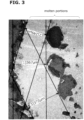
Fig. 3 is a cross section showing a result of an erosion comparison test of tungsten alloy. -
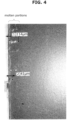
Fig. 4 is a cross section showing a result of an erosion comparison test of composite alloy of theembodiment 1. -
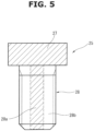
Fig. 5 is a local longitudinal cross section of a conductive bolt of anembodiment 2. -
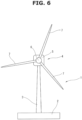
Fig. 6 is a front view of a wind power generation device. -
Fig. 7 is a local sectional view of a blade. - A receptor for a blade of a wind power generation device according to embodiments of the present invention will be described below. As mentioned above, this receptor is used as measures against lightning strike on the blade of the wind power generation device (as measures to protect the blade of the wind power generation device) .
- The wind power generation device will be roughly described with reference to
Fig. 6 . The windpower generation device 1 is constructed mainly by a base (or a foundation) 2 installed on the ground or on the ocean, atower 3 installed on thebase 2 and arotor 4 rotatably installed at a top of thetower 3. - The
rotor 4 has anacelle 5 at the top of thetower 3, ahub 6 fixed to a rotatable spindle (not shown) provided inside thenacelle 5 and a plurality ofblades 7 fixed to thehub 6. - As illustrated in
Fig. 7 , thereceptor 10 as a lightning protection device is fixed to a tip of eachblade 7. Thereceptor 10 is electrically connected to thebase 2, which serves as a ground electrode, through adown conductor 11. - Therefore, when lightning strikes the
receptor 10, a lightning current is conducted to the ground electrode (the base 2) through thedown conductor 11. This downconductor 11 is fixed to a wedge-shaped receptor anchor 12, and thereceptor 10 is secured to thereceptor anchor 12 with an adhesive 13 and bolts 25 (seeFig. 1 ) . Theadhesive 13 fills a gap between thereceptor anchor 12 and theblade 7. - Regarding the
receptor 10, since thereceptor 10 is subject to a centrifugal force when theblades 7 rotate, aluminum alloy, which is lightweight and has excellent workability, has been used conventionally. However, in the windpower generation device 1, a distance from eachblade 7 to thunder cloud is shorter than that from a structure such as thenacelle 5 to the thunder cloud, and thus theblade 7 is subjected to great damage by lightning strike. - As a consequence, there is a risk that expensive repair costs will be incurred. A
lightweight receptor 10 having high lightning resistance is thus desired. In order to realize this point, thereceptors 10 according toembodiments - The
embodiment 1 of thereceptor 10 will be described with reference toFigs. 1 to 4 . Thereceptor 10 in the present embodiment is molded into a hollow structure by a casting mold etc. in order to realize weight reduction. - As illustrated in
Figs. 1 and2 , thereceptor 10 is formed so that ahollow portion 21 is formed inside areceptor body 20. Thisreceptor body 20 has a pair ofside portions Figs. 2(a) and 2(d) ) and abottom portion 22 formed at thereceptor anchor 12 side, which are formed into a substantially triangular shape. - The
hollow portion 21 is formed into a substantially similar shape (but smaller in size) to thereceptor body 20. Thehollow portion 21 is formed in a region from an inside tip of thereceptor body 20 to thebottom portion 22. Thebottom portion 22 is provided with a pair of insertion holes (not shown) . Theside portion 20a is provided with a cutout portion (a cutout space) 29 as an entrance into thehollow portion 21. - It is therefore possible to dispose a
shaft portion 28 of eachbolt 25 in thehollow portion 21 from thecutout portion 29 and insert theshaft portion 28 into the insertion hole. With this, theshaft portion 28 can be fastened to (screwed into) a female threaded hole (not shown) of thereceptor anchor 12 from thehollow portion 21. Further, when replacing thereceptor 10, it is possible to unfasten (unscrew) thebolt 25 from the inside of thehollow portion 21. - The
receptor body 20 is molded using composite alloy (composite metal) described inPatent Document 3 as receptor material. This composite alloy is comprised of a Cu (copper) phase in which a heat-resistant element selectedfromMo (molybdenum), W (tungsten), Ta (tantalum), Nb (niobium), V (vanadium) and Zr (zirconium) and a solid solution particle phase of Cr (chromium) are uniformly dispersed. - The composite alloy in this case contains, in weight ratio relative to the composite alloy, "Cu = 20 to 70%" and "Cr=1.5 to 64%", and the remainder is comprised of inevitable impurities. Further, the solid solution particles contained in the composite alloy have an average particle diameter of 20um or less, and are uniformly dispersed in the Cu phase with a dispersion state index of 1.0 or less. According to the
receptor 10 of the present embodiment described above, the following effects can be obtained. - (1) Because of the hollow structure formed by the
hollow portion 21, it is possible to realize weight reduction as compared with a conventional product that employs a solid structure. That is, although the composite alloy has larger mass than that of aluminum alloy, by employing the hollow structure, weight reduction can be achieved, thereby reducing an influence of the centrifugal force of theblades 7.
In addition, because of the lightweight type, it is possible to easily perform receptor replacement work which is performed while being suspended in the air, thereby improving workability. Further, since thecutout portion 29 is formed at theside portion 20a, it is possible to fasten (screw) and unfasten (unscrew) theshaft portion 28 of thebolt 25 to (into) and from thereceptor anchor 12 from the inside of thehollow portion 21, thereby easily performing the receptor replacement work. - (2) By using the composite alloy as the receptor material, it is possible to obtain the effect of suppressing erosion loss (melting loss) due to lightning strike as compared with the aluminum alloy.
- That is, as a result of performing an erosion comparison test (reference, IEC 61400-24 Ed.2.0/D.3) with the cumulative amount 3000 C (600 C × 5 times), it was confirmed that the composite alloy suppresses the erosion loss (the melting loss) due to lightning strike as compared with the aluminum alloy, and that the erosion loss (the melting loss) is as slight as that of tungsten alloy.
-
Figs. 3 and4 illustrate results of erosion comparison tests of a comparative example (tungsten alloy/W alloy × 300) and the composite alloy. More specifically, when cross-sections of molten portions of the both alloys were examined by an electron microscope, it was found that melting of a surface layer portion of the composite alloy was suppressed more than the tungsten alloy. - In other words, by employing the hollow structure, the composite alloy can be selected as the receptor material, then the
receptor 10 of the present embodiment enhances the effect of suppressing the erosion loss (the melting loss) due to lightning strike. In this respect, thereceptor 10 has high lightning resistance, and can obtain an effect of suppressing damage by the lightning strike to theblades 7. - (3) The composite alloy not only has the effect of suppressing the erosion loss (the melting loss), but is suitable for material of the
receptor 10 in terms of mechanical strength and workability.[Table 1] Receptor Material tensile strength [MPa] (0. 2%) material hardness [HV] aluminum alloy 263 (225) <100 tungsten alloy 1024(665) 347 composite alloy (PP5880789) 671 (477) 276 - Table 1 shows a result of comparison tests on tensile strength and material hardness of the aluminum alloy, the tungsten alloy and the composite alloy. According to this comparison test result, it was confirmed that the composite alloy was superior to the aluminum alloy in the tensile strength, and was softer than the tungsten alloy in hardness. As a result, by employing the composite alloy, the
receptor 10 of the present embodiment can obtain a higher mechanical strength than that of an aluminum alloy-made receptor and higher workability than that of a tungsten alloy-made receptor. - The
embodiment 2 of thereceptor 10 will be described with reference toFig. 5 . In the present embodiment, the composite alloy is used for thebolt 25 for fixing thereceptor 10 to thereceptor anchor 12. Hereinafter, thebolt 25 using the composite alloy is referred to as aconductive bolt 25. - More specifically, the composite alloy having high conductivity is used for a
head portion 27 and aninside part 28a of theshaft portion 28 of theconductive bolt 25. On the other hand, athread 28b of theshaft portion 28 is made of titanium alloy (Ti alloy) having high heat resistance and high corrosion resistance (high erosion resistance). Theconductive bolt 25 in the present embodiment can be manufactured, for instance, by joining the above components by hot isostatic pressing and by cutting and polishing them. - According to the
conductive bolt 25 structured as described above, since a component such as a conductive bushing is not required, a component count decreases, thereby improving workability of maintenance. Further, theconductive bolt 25 can also be used as a side receptor of theblade 7. - Here, in
Patent Document 4, in the same manner as the present embodiment, a tip receptor ofPatent Document 4 is connected using bolts, and there is concern of breakage, damage or scattering of the bolt due to lightning strike. In contrast to this, theconductive bolt 25 of the present embodiment can conduct a lightning current of the lightning strike to thedown conductor 11 side, thereby eliminating the above concern. - The present invention is not limited to the above embodiments, and can be modified and implemented within the scope of the claims. Some examples are shown below.
- (1) Since the
receptor body 20 of theembodiment 1 employs the hollow structure, not only the composite alloy, but also metal having large mass such as tungsten alloy can be used as the receptor material. In this case, such metal can be used as a substitute for the composite alloy in consideration of influence by the centrifugal force etc. in design. - (2) The shape of the
hollow portion 21 is not limited to the substantially similar shape to thereceptor body 20. Thehollow portion 21 could be formed only at thebottom portion 22 side, and the tip side of thereceptor body 20 could be formed into a solid body. Further, thehollow portion 21 may be formed at the tip side of thereceptor body 20 and thebottom portion 22 side, and a portion between both these sides may be formed into a solid body. In addition, thehollow portion 21 might be formed into a honeycomb structure (a porous structure) . - (3) The
bolt 25 is not limited to a round head bolt shown inFigs. 1 and2 , but, for instance, a hexagon head bolt or a turn back bolt could be used. In a case where the turn back bolt is used, a male screw in one direction formed at one end portion side of the turn back bolt is screwed into a female threaded hole of thebottom portion 22, and a male screw in the other direction formed at the other end portion side of the turn back bolt is screwed into a female threaded hole of thereceptor anchor 12, then thereceptor 10 is fixed.
Here, a fixing position (s) of the bolt (s) 25 is not limited to a middle portion of thebottom portion 22 which is shown inFigs. 1 and2 . For instance, the fixing positions may be bothend portions bottom portion 22. - (4) Regarding the
conductive bolt 25 in theembodiment 2, thethread 28b of theshaft portion 28 could be made of the aforementioned composite alloy instead of the titanium alloy. In this case, since the entireconductive bolt 25 is made of the composite alloy, both of thereceptor 10 and theconductive bolt 25 are made of the same material, thereby reducing influence of electric corrosion (electric erosion). Here, theconductive bolt 25 is not limited to a round head bolt, but, for instance, a hexagon head bolt or a turn back bolt could be used. - (5) It is noted that the
receptor body 20 could be provided, at the tip portion thereof, with a drain hole for draining water. Further, in order to suppress damage to thebolt 25, thehead portion 27 may be fixed with an adhesive. -
- 1 ··· wind power generation device
- 2 ··· base
- 3 ··· tower
- 4 ··· rotor
- 5 ··· nacelle
- 6 ··· hub
- 7 ··· blade
- 10 ··· receptor
- 11 ··· down conductor
- 20 ··· receptor body
- 20a, 20b ··· side portions
- 21 ··· hollow portion
- 22 ··· bottom portion
- 23, 24 ··· both end portions
- 25 ··· bolt, conductive bolt
- 27 ··· head portion
- 28 ··· shaft portion
- 28a ··· inside part of shaft portion
- 28b ··· thread of shaft portion
- 29 ··· cutout portion
Claims (5)
- A receptor for a blade of a wind power generation device, the wind power generation device having the blades that rotate by receiving wind and form a rotor, whereinthe receptor is fixed to a tip of each blade, anda hollow portion is formed inside the receptor.
- The receptor for the blade of the wind power generation device as claimed in claim 1, comprising:a receptor body made of composite alloy; andthe hollow portion formed inside the receptor body,wherein the receptor body is made of the composite alloy comprised of a Cu phase in which a heat-resistant element selected from Mo, W, Ta, Nb, V and Zr and a solid solution particle phase of Cr are uniformly dispersed,the composite alloy contains, in weight ratio relative to the composite alloy,20 to 70% of Cu, and1.5 to 64% of Cr, andthe remainder is comprised of inevitable impurities, andthe solid solution particles contained in the composite alloy have an average particle diameter of 20um or less, and are uniformly dispersed in the Cu phase with a dispersion state index of 1.0 or less.
- The receptor for the blade of the wind power generation device as claimed in claim 2, whereinthe receptor body is fixed to a blade side with a bolt,the receptor body is provided with a cutout portion formed as an entrance into the hollow portion, andthe bolt can be fastened to and unfastened from the blade side from an inside of the hollow portion.
- The receptor for the blade of the wind power generation device as claimed in claim 3, wherein
the bolt is made of the composite alloy. - The receptor for the blade of the wind power generation device as claimed in claim 4, whereina head portion and a shaft portion body of the bolt are made of the composite alloy, anda thread of a shaft portion of the bolt is made of titanium alloy.
Applications Claiming Priority (2)
| Application Number | Priority Date | Filing Date | Title |
|---|---|---|---|
| JP2022042936A JP7355142B1 (en) | 2022-03-17 | 2022-03-17 | Receptor for wind turbine blades |
| PCT/JP2023/008083 WO2023176516A1 (en) | 2022-03-17 | 2023-03-03 | Receptor for blade of wind power generation device |
Publications (3)
| Publication Number | Publication Date |
|---|---|
| EP4495422A1 true EP4495422A1 (en) | 2025-01-22 |
| EP4495422A4 EP4495422A4 (en) | 2025-07-30 |
| EP4495422B1 EP4495422B1 (en) | 2026-05-06 |
Family
ID=88022971
Family Applications (1)
| Application Number | Title | Priority Date | Filing Date |
|---|---|---|---|
| EP23770473.9A Active EP4495422B1 (en) | 2022-03-17 | 2023-03-03 | Receptor for blade of wind power generation device |
Country Status (3)
| Country | Link |
|---|---|
| EP (1) | EP4495422B1 (en) |
| JP (2) | JP7355142B1 (en) |
| WO (1) | WO2023176516A1 (en) |
Families Citing this family (1)
| Publication number | Priority date | Publication date | Assignee | Title |
|---|---|---|---|---|
| CN119267079B (en) * | 2024-11-25 | 2025-05-16 | 中材科技风电叶片股份有限公司 | Main beam structure, wind turbine blades and wind turbine generator sets |
Family Cites Families (12)
| Publication number | Priority date | Publication date | Assignee | Title |
|---|---|---|---|---|
| JP4192744B2 (en) * | 2003-10-06 | 2008-12-10 | Jfeエンジニアリング株式会社 | Wind power generation equipment |
| US7766620B2 (en) * | 2007-02-08 | 2010-08-03 | General Electricc Company | Rotor blade with a lightning protection unit, wind energy system having the same and a method for constructing a rotor blade |
| EP2226497A1 (en) * | 2009-03-06 | 2010-09-08 | Lm Glasfiber A/S | Wind turbine blade with a lightning protection system |
| DE102009046586B4 (en) * | 2009-11-10 | 2012-02-23 | Nordex Energy Gmbh | Blade tip for a rotor blade of a wind turbine and method for mounting the blade tip to a rotor blade |
| JP5158730B2 (en) * | 2010-06-30 | 2013-03-06 | 株式会社日本製鋼所 | Lightning protection structure for wind power blades |
| CN103154507B (en) | 2010-07-23 | 2016-08-03 | 爱瑞柯国际公司 | Lightning protected receptor for wind turbine blade |
| JP4939640B2 (en) * | 2010-10-22 | 2012-05-30 | 三菱重工業株式会社 | Wind turbine rotor |
| US20190195203A1 (en) * | 2011-12-09 | 2019-06-27 | Mitsubishi Heavy Industries, Ltd. | Wind turbine blade for a wind turbine |
| JP5880789B1 (en) * | 2014-03-04 | 2016-03-09 | 株式会社明電舎 | A composite metal in which Cu is infiltrated into a compact formed from solid solution particles |
| EP3218596B1 (en) | 2014-11-14 | 2022-10-26 | Polytech A/S | A fully insulated tip unit for a lightning protection system for a wind turbine blade and a wind turbine blade comprising the same |
| JP5941174B1 (en) * | 2015-02-03 | 2016-06-29 | 株式会社日立製作所 | Wind power generator |
| WO2018019349A1 (en) * | 2016-07-29 | 2018-02-01 | Vestas Wind Systems A/S | Wind turbine blade having a lightning tip receptor |
-
2022
- 2022-03-17 JP JP2022042936A patent/JP7355142B1/en active Active
-
2023
- 2023-03-03 EP EP23770473.9A patent/EP4495422B1/en active Active
- 2023-03-03 WO PCT/JP2023/008083 patent/WO2023176516A1/en not_active Ceased
- 2023-06-13 JP JP2023096669A patent/JP7525008B2/en active Active
Also Published As
| Publication number | Publication date |
|---|---|
| EP4495422B1 (en) | 2026-05-06 |
| WO2023176516A1 (en) | 2023-09-21 |
| JP7525008B2 (en) | 2024-07-30 |
| JP7355142B1 (en) | 2023-10-03 |
| JP2023138500A (en) | 2023-10-02 |
| EP4495422A4 (en) | 2025-07-30 |
| JP2023145816A (en) | 2023-10-12 |
Similar Documents
| Publication | Publication Date | Title |
|---|---|---|
| TWI611100B (en) | Wind power generator | |
| US7377750B1 (en) | Lightning protection system for a wind turbine | |
| EP2712472B1 (en) | Wind turbine blade for a wind turbine | |
| EP2227633B1 (en) | Wind turbine blade with lightning receptors comprising carbon nanotubes | |
| DE102007050009A1 (en) | Lightning protection for wind turbines | |
| EP4495422B1 (en) | Receptor for blade of wind power generation device | |
| EP0863072A2 (en) | Electroformed sheath and airfoiled component construction | |
| AU2004272684A1 (en) | A method of lightning-proofing a blade for a wind-energy plant | |
| CN111911345B (en) | Blade for a wind turbine and wind turbine | |
| TWI774387B (en) | Windmill wing, windmill and repair method of windmill wing | |
| EP2075835B1 (en) | Diode with stress reducing means | |
| US20100108342A1 (en) | Layered structure with outer lightning protection surface | |
| US20240068438A1 (en) | Protective cap for a leading edge of a wind turbine blade | |
| US10953978B2 (en) | Propeller counterweight | |
| EP3935280B1 (en) | Electrical connection device for a wind turbine, wind turbine and method for producing an electrical connection device | |
| DE102008033092B4 (en) | Lightning receptor for a rotor blade of a wind energy plant | |
| EP4039841A1 (en) | Conductor | |
| US20230167806A1 (en) | Tip air receptor | |
| EP4172494A1 (en) | Wind turbine blade, wind turbine, method for fabrication of a wind turbine component and method for fabrication of a wind turbine blade | |
| WO2005097387A1 (en) | Electrode for high-speed electrical discharge machining | |
| CN109402461A (en) | A kind of aluminum foil material being used to prepare lightning protection aluminium net | |
| EP4166780A1 (en) | A rotor blade lightning protection system with spark-gaps for equipotential bonds | |
| WO2025036906A1 (en) | Lightning protection in a segmented wind turbine blade | |
| JP2003317995A (en) | Lightning rod member and lightning rod using the same | |
| GB2638847A (en) | Protective coating with bionic structure, and preparation method and use thereof |
Legal Events
| Date | Code | Title | Description |
|---|---|---|---|
| STAA | Information on the status of an ep patent application or granted ep patent |
Free format text: STATUS: THE INTERNATIONAL PUBLICATION HAS BEEN MADE |
|
| PUAI | Public reference made under article 153(3) epc to a published international application that has entered the european phase |
Free format text: ORIGINAL CODE: 0009012 |
|
| STAA | Information on the status of an ep patent application or granted ep patent |
Free format text: STATUS: REQUEST FOR EXAMINATION WAS MADE |
|
| 17P | Request for examination filed |
Effective date: 20240905 |
|
| AK | Designated contracting states |
Kind code of ref document: A1 Designated state(s): AL AT BE BG CH CY CZ DE DK EE ES FI FR GB GR HR HU IE IS IT LI LT LU LV MC ME MK MT NL NO PL PT RO RS SE SI SK SM TR |
|
| DAV | Request for validation of the european patent (deleted) | ||
| DAX | Request for extension of the european patent (deleted) | ||
| A4 | Supplementary search report drawn up and despatched |
Effective date: 20250626 |
|
| RIC1 | Information provided on ipc code assigned before grant |
Ipc: F03D 80/30 20160101AFI20250620BHEP Ipc: F03D 1/06 20060101ALI20250620BHEP |
|
| GRAP | Despatch of communication of intention to grant a patent |
Free format text: ORIGINAL CODE: EPIDOSNIGR1 |
|
| STAA | Information on the status of an ep patent application or granted ep patent |
Free format text: STATUS: GRANT OF PATENT IS INTENDED |
|
| INTG | Intention to grant announced |
Effective date: 20251203 |
|
| GRAS | Grant fee paid |
Free format text: ORIGINAL CODE: EPIDOSNIGR3 |
|
| GRAA | (expected) grant |
Free format text: ORIGINAL CODE: 0009210 |
|
| STAA | Information on the status of an ep patent application or granted ep patent |
Free format text: STATUS: THE PATENT HAS BEEN GRANTED |
|
| AK | Designated contracting states |
Kind code of ref document: B1 Designated state(s): AL AT BE BG CH CY CZ DE DK EE ES FI FR GB GR HR HU IE IS IT LI LT LU LV MC ME MK MT NL NO PL PT RO RS SE SI SK SM TR |
|
| REG | Reference to a national code |
Ref country code: CH Ref legal event code: F10 Free format text: ST27 STATUS EVENT CODE: U-0-0-F10-F00 (AS PROVIDED BY THE NATIONAL OFFICE) Effective date: 20260506 Ref country code: GB Ref legal event code: FG4D |