EP4495402A1 - Bifurcation air scoop for gas turbine engine - Google Patents
Bifurcation air scoop for gas turbine engine Download PDFInfo
- Publication number
- EP4495402A1 EP4495402A1 EP24189519.2A EP24189519A EP4495402A1 EP 4495402 A1 EP4495402 A1 EP 4495402A1 EP 24189519 A EP24189519 A EP 24189519A EP 4495402 A1 EP4495402 A1 EP 4495402A1
- Authority
- EP
- European Patent Office
- Prior art keywords
- air
- airflow chamber
- fan
- radially
- lip
- Prior art date
- Legal status (The legal status is an assumption and is not a legal conclusion. Google has not performed a legal analysis and makes no representation as to the accuracy of the status listed.)
- Granted
Links
Images



Classifications
-
- F—MECHANICAL ENGINEERING; LIGHTING; HEATING; WEAPONS; BLASTING
- F02—COMBUSTION ENGINES; HOT-GAS OR COMBUSTION-PRODUCT ENGINE PLANTS
- F02C—GAS-TURBINE PLANTS; AIR INTAKES FOR JET-PROPULSION PLANTS; CONTROLLING FUEL SUPPLY IN AIR-BREATHING JET-PROPULSION PLANTS
- F02C6/00—Plural gas-turbine plants; Combinations of gas-turbine plants with other apparatus; Adaptations of gas-turbine plants for special use
- F02C6/04—Gas-turbine plants providing heated or pressurised working fluid for other apparatus, e.g. without mechanical power output
- F02C6/06—Gas-turbine plants providing heated or pressurised working fluid for other apparatus, e.g. without mechanical power output providing compressed gas
- F02C6/08—Gas-turbine plants providing heated or pressurised working fluid for other apparatus, e.g. without mechanical power output providing compressed gas the gas being bled from the gas-turbine compressor
-
- F—MECHANICAL ENGINEERING; LIGHTING; HEATING; WEAPONS; BLASTING
- F02—COMBUSTION ENGINES; HOT-GAS OR COMBUSTION-PRODUCT ENGINE PLANTS
- F02C—GAS-TURBINE PLANTS; AIR INTAKES FOR JET-PROPULSION PLANTS; CONTROLLING FUEL SUPPLY IN AIR-BREATHING JET-PROPULSION PLANTS
- F02C7/00—Features, components parts, details or accessories, not provided for in, or of interest apart form groups F02C1/00 - F02C6/00; Air intakes for jet-propulsion plants
- F02C7/04—Air intakes for gas-turbine plants or jet-propulsion plants
- F02C7/057—Control or regulation
-
- B—PERFORMING OPERATIONS; TRANSPORTING
- B64—AIRCRAFT; AVIATION; COSMONAUTICS
- B64D—EQUIPMENT FOR FITTING IN OR TO AIRCRAFT; FLIGHT SUITS; PARACHUTES; ARRANGEMENT OR MOUNTING OF POWER PLANTS OR PROPULSION TRANSMISSIONS IN AIRCRAFT
- B64D13/00—Arrangements or adaptations of air-treatment apparatus for aircraft crew or passengers, or freight space
- B64D13/02—Arrangements or adaptations of air-treatment apparatus for aircraft crew or passengers, or freight space the air being pressurised
-
- F—MECHANICAL ENGINEERING; LIGHTING; HEATING; WEAPONS; BLASTING
- F02—COMBUSTION ENGINES; HOT-GAS OR COMBUSTION-PRODUCT ENGINE PLANTS
- F02C—GAS-TURBINE PLANTS; AIR INTAKES FOR JET-PROPULSION PLANTS; CONTROLLING FUEL SUPPLY IN AIR-BREATHING JET-PROPULSION PLANTS
- F02C7/00—Features, components parts, details or accessories, not provided for in, or of interest apart form groups F02C1/00 - F02C6/00; Air intakes for jet-propulsion plants
- F02C7/12—Cooling of plants
-
- F—MECHANICAL ENGINEERING; LIGHTING; HEATING; WEAPONS; BLASTING
- F02—COMBUSTION ENGINES; HOT-GAS OR COMBUSTION-PRODUCT ENGINE PLANTS
- F02C—GAS-TURBINE PLANTS; AIR INTAKES FOR JET-PROPULSION PLANTS; CONTROLLING FUEL SUPPLY IN AIR-BREATHING JET-PROPULSION PLANTS
- F02C9/00—Controlling gas-turbine plants; Controlling fuel supply in air- breathing jet-propulsion plants
- F02C9/16—Control of working fluid flow
- F02C9/18—Control of working fluid flow by bleeding, bypassing or acting on variable working fluid interconnections between turbines or compressors or their stages
-
- B—PERFORMING OPERATIONS; TRANSPORTING
- B64—AIRCRAFT; AVIATION; COSMONAUTICS
- B64D—EQUIPMENT FOR FITTING IN OR TO AIRCRAFT; FLIGHT SUITS; PARACHUTES; ARRANGEMENT OR MOUNTING OF POWER PLANTS OR PROPULSION TRANSMISSIONS IN AIRCRAFT
- B64D13/00—Arrangements or adaptations of air-treatment apparatus for aircraft crew or passengers, or freight space
- B64D13/06—Arrangements or adaptations of air-treatment apparatus for aircraft crew or passengers, or freight space the air being conditioned
- B64D2013/0603—Environmental Control Systems
- B64D2013/0618—Environmental Control Systems with arrangements for reducing or managing bleed air, using another air source, e.g. ram air
-
- F—MECHANICAL ENGINEERING; LIGHTING; HEATING; WEAPONS; BLASTING
- F05—INDEXING SCHEMES RELATING TO ENGINES OR PUMPS IN VARIOUS SUBCLASSES OF CLASSES F01-F04
- F05D—INDEXING SCHEME FOR ASPECTS RELATING TO NON-POSITIVE-DISPLACEMENT MACHINES OR ENGINES, GAS-TURBINES OR JET-PROPULSION PLANTS
- F05D2260/00—Function
- F05D2260/20—Heat transfer, e.g. cooling
- F05D2260/213—Heat transfer, e.g. cooling by the provision of a heat exchanger within the cooling circuit
Definitions
- This application relates to an air scoop for supplying air for two distinct purposes from a bifurcation in a gas turbine engine.
- Gas turbine engines typically include a fan delivering air into a bypass duct as propulsion air.
- An outer fan case surrounds the fan.
- the fan also delivers air into an inner core housing, and into a compressor section.
- the air is compressed and delivered into a combustor where it is mixed with fuel and ignited. Products of this combustion pass downstream over turbine rotors, driving them to rotate.
- a bifurcation extends radially between the inner core housing and the fan case to secure the two.
- Air is needed for a gas turbine engine for a number of reasons.
- the gas turbine engine may also supply air for application and use on an aircraft.
- cooling air is typically supplied within the inner core housing.
- a gas turbine engine in an aspect of the present invention, includes a fan received within a fan case, the fan delivers bypass air into a bypass duct between an inner radial portion (e.g., an inner radial surface relative to a central axis of the engine) of the fan case and an outer radial surface of an inner core housing.
- the fan delivers air into the inner core housing.
- a compressor section, a combustor and a turbine section are within the inner core housing.
- a bifurcation extends radially to connect the inner core housing to the fan case.
- the bifurcation has a forward opening defining an air scoop.
- the air scoop separates air into a first airflow chamber connected downstream to a precooler.
- the precooler has a connection to receive compressed air from the compressor section.
- the air in the bypass duct is delivered to the precooler (e.g., the bypass duct, bifurcation or air scoop is configured to delivered air to the precooler) for cooling the compressed air in the precooler.
- the air scoop defines a second airflow chamber for delivering cooling air to components within the inner core housing.
- the first airflow chamber may be defined by a lip at a central location (e.g., a central lateral location and/or a central radial location) within the air scoop.
- the second airflow chamber may be defined laterally outwardly on both of two lateral sides of the lip.
- the second airflow chamber may be defined radially outwardly and radially inwardly of the lip.
- the air scoop may extend between a radially outer end and a radially inner end, with a first distance defined between the radially outer end and the radially inner end (a first distance is defined between a radially outer end of the air scoop and a radially inner end of the air scoop), and a radial distance between a radially outer end of the lip and a radially inner end of the lip may be greater than half of the first distance (a second distance defined between a radially outer end of the lip and a radially inner end of the lip is greater than half of the first distance).
- a radially outer end of the second airflow chamber may be spaced from a radially inner end of the second airflow chamber by a distance that is greater than half of the first distance (a third distance defined between a radially outer end of the second airflow chamber and a radially inner end of the second airflow chamber is greater than half of the first distance).
- the second airflow chamber may be connected into a connection receiving a valve (the second airflow chamber is connected to a valved connection).
- an aircraft air supply system in another aspect of the present invention, includes an environmental control system for delivering air to an aircraft cabin.
- a fan is received within a fan case.
- the fan delivers bypass air into a bypass duct between an inner radial portion (e.g., an inner radial surface relative to a central axis of the engine) of the fan case and an outer radial surface of an inner core housing.
- the fan delivers air into the inner core housing.
- a compressor section, a combustor and a turbine section are within the inner core housing.
- a bifurcation extends radially to connect the inner core housing to the fan case.
- the bifurcation has a forward opening defining an air scoop. The air scoop separates air into a first airflow chamber connected downstream to a precooler.
- the precooler has a connection to receive compressed air from the compressor section.
- the air in the bypass duct is delivered to the precooler (e.g., the bypass duct, bifurcation or air scoop is configured to delivered air to the precooler) for cooling the compressed air in the precooler.
- the compressed air is delivered from the precooler to the environmental control system (e.g., the precooler is configured to deliver air to the environmental control system).
- the air scoop defines a second airflow chamber for delivering cooling air to components within the inner core housing.
- the first airflow chamber may be defined by a lip at a central location (e.g., a central lateral location and/or a central radial location) within the air scoop.
- the second airflow chamber may be defined laterally outwardly on both of two lateral sides of the lip.
- the second airflow chamber may be defined radially outwardly and radially inwardly of the lip.
- the air scoop may extend between a radially outer end and a radially inner end, with a first distance defined between the radially outer end and the radially inner end (a first distance is defined between a radially outer end of the air scoop and a radially inner end of the air scoop), and a radial distance between a radially outer end of the lip and a radially inner end of the lip may be greater than half of the first distance (a second distance defined between a radially outer end of the lip and a radially inner end of the lip is greater than half of the first distance).
- a radially outer end of the second airflow chamber may be spaced from a radially inner end of the second airflow chamber by a distance that is greater than half of the first distance (a third distance defined between a radially outer end of the second airflow chamber and a radially inner end of the second airflow chamber is greater than half of the first distance).
- the second airflow chamber may be connected into a connection receiving a valve (the second airflow chamber is connected to a valved connection).
- the present invention may include any one or more of the individual features disclosed above and/or below alone or in any combination thereof.
- FIG. 1 schematically illustrates a gas turbine engine 20.
- the gas turbine engine 20 is disclosed herein as a two-spool turbofan that generally incorporates a fan section 22, a compressor section 24, a combustor section 26 and a turbine section 28.
- the fan section 22 may include a single-stage fan 42 having a plurality of fan blades 43.
- the fan blades 43 may have a fixed stagger angle or may have a variable pitch to direct incoming airflow from an engine inlet.
- the fan 42 drives air along a bypass flow path B in a bypass duct 13 defined within a housing 15 such as a fan case or nacelle, and also drives air along a core flow path C for compression and communication into the combustor section 26 then expansion through the turbine section 28.
- a splitter 29 aft of the fan 42 divides the air between the bypass flow path B and the core flow path C.
- the housing 15 may surround the fan 42 to establish an outer diameter of the bypass duct 13.
- the splitter 29 may establish an inner diameter of the bypass duct 13.
- the exemplary engine 20 generally includes a low speed spool 30 and a high speed spool 32 mounted for rotation about an engine central longitudinal axis A relative to an engine static structure 36 via several bearing systems 38. It should be understood that various bearing systems 38 at various locations may alternatively or additionally be provided, and the location of bearing systems 38 may be varied as appropriate to the application.
- the low speed spool 30 generally includes an inner shaft 40 that interconnects, a first (or low) pressure compressor 44 and a first (or low) pressure turbine 46.
- the inner shaft 40 is connected to the fan 42 through a speed change mechanism, which in the exemplary gas turbine engine 20 is illustrated as a geared architecture 48 to drive the fan 42 at a lower speed than the low speed spool 30.
- the inner shaft 40 may interconnect the low pressure compressor 44 and low pressure turbine 46 such that the low pressure compressor 44 and low pressure turbine 46 are rotatable at a common speed and in a common direction.
- the low pressure turbine 46 drives both the fan 42 and low pressure compressor 44 through the geared architecture 48 such that the fan 42 and low pressure compressor 44 are rotatable at a common speed.
- the high speed spool 32 includes an outer shaft 50 that interconnects a second (or high) pressure compressor 52 and a second (or high) pressure turbine 54.
- a combustor 56 is arranged in the exemplary gas turbine 20 between the high pressure compressor 52 and the high pressure turbine 54.
- a mid-turbine frame 57 of the engine static structure 36 may be arranged generally between the high pressure turbine 54 and the low pressure turbine 46.
- the mid-turbine frame 57 further supports bearing systems 38 in the turbine section 28.
- the inner shaft 40 and the outer shaft 50 are concentric and rotate via bearing systems 38 about the engine central longitudinal axis A which is collinear with their longitudinal axes.
- Airflow in the core flow path C is compressed by the low pressure compressor 44 then the high pressure compressor 52, mixed and burned with fuel in the combustor 56, then expanded through the high pressure turbine 54 and low pressure turbine 46.
- the mid-turbine frame 57 includes airfoils 59 which are in the core flow path C.
- the turbines 46, 54 rotationally drive the respective low speed spool 30 and high speed spool 32 in response to the expansion.
- gear system 48 may be located aft of the low pressure compressor, or aft of the combustor section 26 or even aft of turbine section 28, and fan 42 may be positioned forward or aft of the location of gear system 48.
- the fan 42 may have at least 10 fan blades 43 but no more than 20 or 24 fan blades 43. In examples, the fan 42 may have between 12 and 18 fan blades 43, such as 14 fan blades 43.
- An exemplary fan size measurement is a maximum radius between the tips of the fan blades 43 and the engine central longitudinal axis A. The maximum radius of the fan blades 43 can be at least 40 inches, or more narrowly no more than 75 inches. For example, the maximum radius of the fan blades 43 can be between 45 inches and 60 inches, such as between 50 inches and 55 inches.
- Another exemplary fan size measurement is a hub radius, which is defined as distance between a hub of the fan 42 at a location of the leading edges of the fan blades 43 and the engine central longitudinal axis A.
- the fan blades 43 may establish a fan hub-to-tip ratio, which is defined as a ratio of the hub radius divided by the maximum radius of the fan 42.
- the fan hub-to-tip ratio can be less than or equal to 0.35, or more narrowly greater than or equal to 0.20, such as between 0.25 and 0.30.
- the combination of fan blade counts and fan hub-to-tip ratios disclosed herein can provide the engine 20 with a relatively compact fan arrangement.
- the low pressure compressor 44, high pressure compressor 52, high pressure turbine 54 and low pressure turbine 46 each include one or more stages having a row of rotatable airfoils. Each stage may include a row of vanes adjacent the rotatable airfoils.
- the rotatable airfoils are schematically indicated at 47, and the vanes are schematically indicated at 49.
- the low pressure compressor 44 and low pressure turbine 46 can include an equal number of stages.
- the engine 20 can include a three-stage low pressure compressor 44, an eight-stage high pressure compressor 52, a two-stage high pressure turbine 54, and a three-stage low pressure turbine 46 to provide a total of sixteen stages.
- the low pressure compressor 44 includes a different (e.g., greater) number of stages than the low pressure turbine 46.
- the engine 20 can include a five-stage low pressure compressor 44, a nine-stage high pressure compressor 52, a two-stage high pressure turbine 54, and a four-stage low pressure turbine 46 to provide a total of twenty stages.
- the engine 20 includes a four-stage low pressure compressor 44, a nine-stage high pressure compressor 52, a two-stage high pressure turbine 54, and a three-stage low pressure turbine 46 to provide a total of eighteen stages. It should be understood that the engine 20 can incorporate other compressor and turbine stage counts, including any combination of stages disclosed herein.
- the engine 20 may be a high-bypass geared aircraft engine.
- the bypass ratio can be greater than or equal to 10.0 and less than or equal to about 18.0, or more narrowly can be less than or equal to 16.0.
- the geared architecture 48 may be an epicyclic gear train, such as a planetary gear system or a star gear system.
- the epicyclic gear train may include a sun gear, a ring gear, a plurality of intermediate gears meshing with the sun gear and ring gear, and a carrier that supports the intermediate gears.
- the sun gear may provide an input to the gear train.
- the ring gear (e.g., star gear system) or carrier (e.g., planetary gear system) may provide an output of the gear train to drive the fan 42.
- a gear reduction ratio may be greater than or equal to 2.3, or more narrowly greater than or equal to 3.0, and in some embodiments the gear reduction ratio is greater than or equal to 3.4.
- the gear reduction ratio may be less than or equal to 4.0.
- the fan diameter is significantly larger than that of the low pressure compressor 44.
- the low pressure turbine 46 can have a pressure ratio that is greater than or equal to 8.0 and in some embodiments is greater than or equal to 10.0.
- the low pressure turbine pressure ratio can be less than or equal to 13.0, or more narrowly less than or equal to 12.0.
- Low pressure turbine 46 pressure ratio is pressure measured prior to an inlet of low pressure turbine 46 as related to the pressure at the outlet of the low pressure turbine 46 prior to an exhaust nozzle. It should be understood, however, that the above parameters are only exemplary of one embodiment of a geared architecture engine and that the present invention is applicable to other gas turbine engines including direct drive turbofans. All of these parameters are measured at the cruise condition described below.
- the fan section 22 of the engine 20 is designed for a particular flight condition -- typically cruise at about 0.8 Mach and about 35,000 feet (10,668 meters).
- the flight condition of 0.8 Mach and 35,000 ft (10,668 meters), with the engine at its best fuel consumption - also known as "bucket cruise Thrust Specific Fuel Consumption ('TSFC')" - is the industry standard parameter of lbm of fuel being burned divided by lbf of thrust the engine produces at that minimum point.
- 'TSFC' Thrust Specific Fuel Consumption
- Fan pressure ratio is the pressure ratio across the fan blade 43 alone, without a Fan Exit Guide Vane (“FEGV”) system.
- a distance is established in a radial direction between the inner and outer diameters of the bypass duct 13 at an axial position corresponding to a leading edge of the splitter 29 relative to the engine central longitudinal axis A.
- the fan pressure ratio is a spanwise average of the pressure ratios measured across the fan blade 43 alone over radial positions corresponding to the distance.
- the fan pressure ratio can be less than or equal to 1.45, or more narrowly greater than or equal to 1.25, such as between 1.30 and 1.40.
- “Corrected fan tip speed” is the actual fan tip speed in ft/sec divided by an industry standard temperature correction of [(Tram °R) / (518.7 °R)] 0.5 .
- the corrected fan tip speed can be less than or equal to 1,150.0 ft / second (350.5 meters/second), and can be greater than or equal to 1,000.0 ft / second (304.8 meters/second).
- the fan 42, low pressure compressor 44 and high pressure compressor 52 can provide different amounts of compression of the incoming airflow that is delivered downstream to the turbine section 28 and cooperate to establish an overall pressure ratio (OPR).
- OPR is a product of the fan pressure ratio across a root (i.e., 0% span) of the fan blade 43 alone, a pressure ratio across the low pressure compressor 44 and a pressure ratio across the high pressure compressor 52.
- the pressure ratio of the low pressure compressor 44 is measured as the pressure at the exit of the low pressure compressor 44 divided by the pressure at the inlet of the low pressure compressor 44.
- a sum of the pressure ratio of the low pressure compressor 44 and the fan pressure ratio is between 3.0 and 6.0, or more narrowly is between 4.0 and 5.5.
- the pressure ratio of the high pressure compressor ratio 52 is measured as the pressure at the exit of the high pressure compressor 52 divided by the pressure at the inlet of the high pressure compressor 52.
- the pressure ratio of the high pressure compressor 52 is between 9.0 and 12.0, or more narrowly is between 10.0 and 11.5.
- the OPR can be equal to or greater than 45.0, and can be less than or equal to 70.0, such as between 50.0 and 60.0.
- the overall and compressor pressure ratios disclosed herein are measured at the cruise condition described above, and can be utilized in two-spool architectures such as the engine 20 as well as three-spool engine architectures.
- the engine 20 establishes a turbine entry temperature (TET).
- TET turbine entry temperature
- the TET is defined as a maximum temperature of combustion products communicated to an inlet of the turbine section 28 at a maximum takeoff (MTO) condition.
- MTO maximum takeoff
- the inlet is established at the leading edges of the axially forwardmost row of airfoils of the turbine section 28, and MTO is measured at maximum thrust of the engine 20 at static sea-level and 86 degrees Fahrenheit (°F) (30 °C).
- the TET may be greater than or equal to 2,700.0 °F (1,480 °C), or more narrowly less than or equal to 3,500.0 °F (1,930 °C), such as between 2,750.0 °F (1,510 °C) and 3350.0 °F (1,850 °C).
- the relatively high TET can be utilized in combination with the other techniques disclosed herein to provide a compact turbine arrangement.
- the engine 20 establishes an exhaust gas temperature (EGT).
- EGT is defined as a maximum temperature of combustion products in the core flow path C communicated to at the trailing edges of the axially aftmost row of airfoils of the turbine section 28 at the MTO condition.
- the EGT may be less than or equal to 1,000.0 °F (540 °C), or more narrowly greater than or equal to 800.0 °F (425 °C), such as between 900.0 °F (480 °C) and 975.0 °F (525 °C).
- the relatively low EGT can be utilized in combination with the other techniques disclosed herein to reduce fuel consumption.
- Figure 2 shows a gas turbine engine 100 having a fan case 102 that surrounds a fan.
- An inner core housing 104 surrounds a compressor section. The operation of the fan and compressor and the housings as discussed to this point may be generally as shown and described in Figure 1 .
- a bifurcation 106 extends radially to connect the inner core housing 104 to the fan case 102.
- An air scoop 110 is positioned in the bifurcation 106 to receive air.
- the air scoop 110 delivers air across a precooler 112 through a conduit 114.
- Precooler 112 is also shown receiving a supply of air 113 such as from a compressor in the compressor section and delivering that air to a use 115 such as an environmental control system on an associated aircraft. Air is also delivered into the inner core housing 104 at 108.
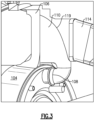
- Figure 3 shows a detail of the connection 108 receiving air downstream of the air scoop 110 and delivering that air into the inner core housing 104.
- Conduit 114 is shown extending away from the air scoop 110.
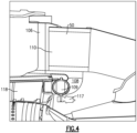
- Figure 4 shows the connection 108 receiving a valve 109.
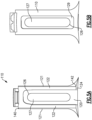
- the scoop 110 extends from a radially outer end 140 and a radially inner end 142.
- Side chambers 122 and a central chamber 127 extend for over a majority of a distance defined between ends 140 and 142.
- the chambers 122 have portions on each lateral side of a lip 126.
- the lip 126 can be seen to not extend for a radial distance as great as the radial distance of the chambers 122.
- a forward end 121 of the scoop 110 defines a central entrance chamber 120.
- Chamber 120 communicates to opposed side chamber 122.
- Central lip 126 defines central chamber 127.
- Chamber 120 also communicates with chamber 127.
- a radially inner end 124 of the side chambers 122 is to connected to the connection 108.
- Central chamber 127 is connected to the conduit 114.
- central chamber 127 moves to be an enlarged chamber 129 once downstream of the lip 126.
- the central lip 126 separates the chambers 122 and 127, air is delivered to the two connections from those two separate locations.
- Figure 5D is another view of the connection, although here without the cutaway through the middle of Figure 5C .
- the sides portions 119 guide the air to connection 124 to conduit 108.
- the central chamber 127 is connected in the conduit 114.
Landscapes
- Engineering & Computer Science (AREA)
- Chemical & Material Sciences (AREA)
- Combustion & Propulsion (AREA)
- Mechanical Engineering (AREA)
- General Engineering & Computer Science (AREA)
- Health & Medical Sciences (AREA)
- General Health & Medical Sciences (AREA)
- Pulmonology (AREA)
- Aviation & Aerospace Engineering (AREA)
- Physics & Mathematics (AREA)
- Fluid Mechanics (AREA)
- Structures Of Non-Positive Displacement Pumps (AREA)
Abstract
Description
- This application relates to an air scoop for supplying air for two distinct purposes from a bifurcation in a gas turbine engine.
- Gas turbine engines are known, and typically include a fan delivering air into a bypass duct as propulsion air. An outer fan case surrounds the fan. The fan also delivers air into an inner core housing, and into a compressor section. The air is compressed and delivered into a combustor where it is mixed with fuel and ignited. Products of this combustion pass downstream over turbine rotors, driving them to rotate.
- As known, a bifurcation extends radially between the inner core housing and the fan case to secure the two. Air is needed for a gas turbine engine for a number of reasons. As an example, the gas turbine engine may also supply air for application and use on an aircraft. In addition, cooling air is typically supplied within the inner core housing.
- In an aspect of the present invention, a gas turbine engine includes a fan received within a fan case, the fan delivers bypass air into a bypass duct between an inner radial portion (e.g., an inner radial surface relative to a central axis of the engine) of the fan case and an outer radial surface of an inner core housing. The fan delivers air into the inner core housing. A compressor section, a combustor and a turbine section are within the inner core housing. A bifurcation extends radially to connect the inner core housing to the fan case. The bifurcation has a forward opening defining an air scoop. The air scoop separates air into a first airflow chamber connected downstream to a precooler. The precooler has a connection to receive compressed air from the compressor section. The air in the bypass duct is delivered to the precooler (e.g., the bypass duct, bifurcation or air scoop is configured to delivered air to the precooler) for cooling the compressed air in the precooler. The air scoop defines a second airflow chamber for delivering cooling air to components within the inner core housing.
- In any of the aspects or embodiments described above and herein, the first airflow chamber may be defined by a lip at a central location (e.g., a central lateral location and/or a central radial location) within the air scoop.
- In any of the aspects or embodiments described above and herein, the second airflow chamber may be defined laterally outwardly on both of two lateral sides of the lip.
- In any of the aspects or embodiments described above and herein, the second airflow chamber may be defined radially outwardly and radially inwardly of the lip.
- In any of the aspects or embodiments described above and herein, the air scoop may extend between a radially outer end and a radially inner end, with a first distance defined between the radially outer end and the radially inner end (a first distance is defined between a radially outer end of the air scoop and a radially inner end of the air scoop), and a radial distance between a radially outer end of the lip and a radially inner end of the lip may be greater than half of the first distance (a second distance defined between a radially outer end of the lip and a radially inner end of the lip is greater than half of the first distance).
- In any of the aspects or embodiments described above and herein, a radially outer end of the second airflow chamber may be spaced from a radially inner end of the second airflow chamber by a distance that is greater than half of the first distance (a third distance defined between a radially outer end of the second airflow chamber and a radially inner end of the second airflow chamber is greater than half of the first distance).
- In any of the aspects or embodiments described above and herein, the second airflow chamber may be connected into a connection receiving a valve (the second airflow chamber is connected to a valved connection).
- In another aspect of the present invention, an aircraft air supply system includes an environmental control system for delivering air to an aircraft cabin. A fan is received within a fan case. The fan delivers bypass air into a bypass duct between an inner radial portion (e.g., an inner radial surface relative to a central axis of the engine) of the fan case and an outer radial surface of an inner core housing. The fan delivers air into the inner core housing. A compressor section, a combustor and a turbine section are within the inner core housing. A bifurcation extends radially to connect the inner core housing to the fan case. The bifurcation has a forward opening defining an air scoop. The air scoop separates air into a first airflow chamber connected downstream to a precooler. The precooler has a connection to receive compressed air from the compressor section. The air in the bypass duct is delivered to the precooler (e.g., the bypass duct, bifurcation or air scoop is configured to delivered air to the precooler) for cooling the compressed air in the precooler. The compressed air is delivered from the precooler to the environmental control system (e.g., the precooler is configured to deliver air to the environmental control system). The air scoop defines a second airflow chamber for delivering cooling air to components within the inner core housing.
- In any of the aspects or embodiments described above and herein, the first airflow chamber may be defined by a lip at a central location (e.g., a central lateral location and/or a central radial location) within the air scoop.
- In any of the aspects or embodiments described above and herein, the second airflow chamber may be defined laterally outwardly on both of two lateral sides of the lip.
- In any of the aspects or embodiments described above and herein, the second airflow chamber may be defined radially outwardly and radially inwardly of the lip.
- In any of the aspects or embodiments described above and herein, the air scoop may extend between a radially outer end and a radially inner end, with a first distance defined between the radially outer end and the radially inner end (a first distance is defined between a radially outer end of the air scoop and a radially inner end of the air scoop), and a radial distance between a radially outer end of the lip and a radially inner end of the lip may be greater than half of the first distance (a second distance defined between a radially outer end of the lip and a radially inner end of the lip is greater than half of the first distance).
- In any of the aspects or embodiments described above and herein, a radially outer end of the second airflow chamber may be spaced from a radially inner end of the second airflow chamber by a distance that is greater than half of the first distance (a third distance defined between a radially outer end of the second airflow chamber and a radially inner end of the second airflow chamber is greater than half of the first distance).
- In any of the aspects or embodiments described above and herein, the second airflow chamber may be connected into a connection receiving a valve (the second airflow chamber is connected to a valved connection).
- The present invention may include any one or more of the individual features disclosed above and/or below alone or in any combination thereof.
- These and other features of the present invention can be best understood from the following specification and drawings, the following of which is a brief description.
-
-
Figure 1 schematically shows a gas turbine engine. -
Figure 2 shows details of a gas turbine engine. -
Figure 3 shows an enlarged portion of an air scoop and bifurcation. -
Figure 4 shows a supply of air from the air scoop into a core engine housing. -
Figure 5A shows a forward aft looking view of the air scoop. -
Figure 5B shows an aft forward looking view of the air scoop. -
Figure 5C shows two separate airflows within the air scoop. -
Figure 5D shows the two separate airflows moving to downstream uses. -
Figure 1 schematically illustrates agas turbine engine 20. Thegas turbine engine 20 is disclosed herein as a two-spool turbofan that generally incorporates afan section 22, a compressor section 24, acombustor section 26 and aturbine section 28. Thefan section 22 may include a single-stage fan 42 having a plurality offan blades 43. Thefan blades 43 may have a fixed stagger angle or may have a variable pitch to direct incoming airflow from an engine inlet. Thefan 42 drives air along a bypass flow path B in abypass duct 13 defined within ahousing 15 such as a fan case or nacelle, and also drives air along a core flow path C for compression and communication into thecombustor section 26 then expansion through theturbine section 28. Asplitter 29 aft of thefan 42 divides the air between the bypass flow path B and the core flow path C. Thehousing 15 may surround thefan 42 to establish an outer diameter of thebypass duct 13. Thesplitter 29 may establish an inner diameter of thebypass duct 13. Although depicted as a two-spool turbofan gas turbine engine in the disclosed non-limiting embodiment, it should be understood that the concepts described herein are not limited to use with two-spool turbofans as the teachings may be applied to other types of turbine engines including three-spool architectures. Theengine 20 may incorporate a variable area nozzle for varying an exit area of the bypass flow path B and/or a thrust reverser for generating reverse thrust. - The
exemplary engine 20 generally includes alow speed spool 30 and ahigh speed spool 32 mounted for rotation about an engine central longitudinal axis A relative to an enginestatic structure 36 viaseveral bearing systems 38. It should be understood that various bearingsystems 38 at various locations may alternatively or additionally be provided, and the location of bearingsystems 38 may be varied as appropriate to the application. - The
low speed spool 30 generally includes aninner shaft 40 that interconnects, a first (or low) pressure compressor 44 and a first (or low)pressure turbine 46. Theinner shaft 40 is connected to thefan 42 through a speed change mechanism, which in the exemplarygas turbine engine 20 is illustrated as a gearedarchitecture 48 to drive thefan 42 at a lower speed than thelow speed spool 30. Theinner shaft 40 may interconnect the low pressure compressor 44 andlow pressure turbine 46 such that the low pressure compressor 44 andlow pressure turbine 46 are rotatable at a common speed and in a common direction. In other embodiments, thelow pressure turbine 46 drives both thefan 42 and low pressure compressor 44 through the gearedarchitecture 48 such that thefan 42 and low pressure compressor 44 are rotatable at a common speed. Although this application discloses gearedarchitecture 48, its teaching may benefit direct drive engines having no geared architecture. Thehigh speed spool 32 includes anouter shaft 50 that interconnects a second (or high) pressure compressor 52 and a second (or high)pressure turbine 54. Acombustor 56 is arranged in theexemplary gas turbine 20 between the high pressure compressor 52 and thehigh pressure turbine 54. Amid-turbine frame 57 of the enginestatic structure 36 may be arranged generally between thehigh pressure turbine 54 and thelow pressure turbine 46. Themid-turbine frame 57 furthersupports bearing systems 38 in theturbine section 28. Theinner shaft 40 and theouter shaft 50 are concentric and rotate via bearingsystems 38 about the engine central longitudinal axis A which is collinear with their longitudinal axes. - Airflow in the core flow path C is compressed by the low pressure compressor 44 then the high pressure compressor 52, mixed and burned with fuel in the
combustor 56, then expanded through thehigh pressure turbine 54 andlow pressure turbine 46. Themid-turbine frame 57 includesairfoils 59 which are in the core flow path C. Theturbines low speed spool 30 andhigh speed spool 32 in response to the expansion. It will be appreciated that each of the positions of thefan section 22, compressor section 24,combustor section 26,turbine section 28, and fandrive gear system 48 may be varied. For example,gear system 48 may be located aft of the low pressure compressor, or aft of thecombustor section 26 or even aft ofturbine section 28, andfan 42 may be positioned forward or aft of the location ofgear system 48. - The
fan 42 may have at least 10fan blades 43 but no more than 20 or 24fan blades 43. In examples, thefan 42 may have between 12 and 18fan blades 43, such as 14fan blades 43. An exemplary fan size measurement is a maximum radius between the tips of thefan blades 43 and the engine central longitudinal axis A. The maximum radius of thefan blades 43 can be at least 40 inches, or more narrowly no more than 75 inches. For example, the maximum radius of thefan blades 43 can be between 45 inches and 60 inches, such as between 50 inches and 55 inches. Another exemplary fan size measurement is a hub radius, which is defined as distance between a hub of thefan 42 at a location of the leading edges of thefan blades 43 and the engine central longitudinal axis A. Thefan blades 43 may establish a fan hub-to-tip ratio, which is defined as a ratio of the hub radius divided by the maximum radius of thefan 42. The fan hub-to-tip ratio can be less than or equal to 0.35, or more narrowly greater than or equal to 0.20, such as between 0.25 and 0.30. The combination of fan blade counts and fan hub-to-tip ratios disclosed herein can provide theengine 20 with a relatively compact fan arrangement. - The low pressure compressor 44, high pressure compressor 52,
high pressure turbine 54 andlow pressure turbine 46 each include one or more stages having a row of rotatable airfoils. Each stage may include a row of vanes adjacent the rotatable airfoils. The rotatable airfoils are schematically indicated at 47, and the vanes are schematically indicated at 49. - The low pressure compressor 44 and
low pressure turbine 46 can include an equal number of stages. For example, theengine 20 can include a three-stage low pressure compressor 44, an eight-stage high pressure compressor 52, a two-stagehigh pressure turbine 54, and a three-stagelow pressure turbine 46 to provide a total of sixteen stages. In other examples, the low pressure compressor 44 includes a different (e.g., greater) number of stages than thelow pressure turbine 46. For example, theengine 20 can include a five-stage low pressure compressor 44, a nine-stage high pressure compressor 52, a two-stagehigh pressure turbine 54, and a four-stagelow pressure turbine 46 to provide a total of twenty stages. In other embodiments, theengine 20 includes a four-stage low pressure compressor 44, a nine-stage high pressure compressor 52, a two-stagehigh pressure turbine 54, and a three-stagelow pressure turbine 46 to provide a total of eighteen stages. It should be understood that theengine 20 can incorporate other compressor and turbine stage counts, including any combination of stages disclosed herein. - The
engine 20 may be a high-bypass geared aircraft engine. The bypass ratio can be greater than or equal to 10.0 and less than or equal to about 18.0, or more narrowly can be less than or equal to 16.0. The gearedarchitecture 48 may be an epicyclic gear train, such as a planetary gear system or a star gear system. The epicyclic gear train may include a sun gear, a ring gear, a plurality of intermediate gears meshing with the sun gear and ring gear, and a carrier that supports the intermediate gears. The sun gear may provide an input to the gear train. The ring gear (e.g., star gear system) or carrier (e.g., planetary gear system) may provide an output of the gear train to drive thefan 42. A gear reduction ratio may be greater than or equal to 2.3, or more narrowly greater than or equal to 3.0, and in some embodiments the gear reduction ratio is greater than or equal to 3.4. The gear reduction ratio may be less than or equal to 4.0. The fan diameter is significantly larger than that of the low pressure compressor 44. Thelow pressure turbine 46 can have a pressure ratio that is greater than or equal to 8.0 and in some embodiments is greater than or equal to 10.0. The low pressure turbine pressure ratio can be less than or equal to 13.0, or more narrowly less than or equal to 12.0.Low pressure turbine 46 pressure ratio is pressure measured prior to an inlet oflow pressure turbine 46 as related to the pressure at the outlet of thelow pressure turbine 46 prior to an exhaust nozzle. It should be understood, however, that the above parameters are only exemplary of one embodiment of a geared architecture engine and that the present invention is applicable to other gas turbine engines including direct drive turbofans. All of these parameters are measured at the cruise condition described below. - A significant amount of thrust is provided by the bypass flow B due to the high bypass ratio. The
fan section 22 of theengine 20 is designed for a particular flight condition -- typically cruise at about 0.8 Mach and about 35,000 feet (10,668 meters). The flight condition of 0.8 Mach and 35,000 ft (10,668 meters), with the engine at its best fuel consumption - also known as "bucket cruise Thrust Specific Fuel Consumption ('TSFC')" - is the industry standard parameter of lbm of fuel being burned divided by lbf of thrust the engine produces at that minimum point. The engine parameters described above, and those in the next paragraph are measured at this condition unless otherwise specified. - "Fan pressure ratio" is the pressure ratio across the
fan blade 43 alone, without a Fan Exit Guide Vane ("FEGV") system. A distance is established in a radial direction between the inner and outer diameters of thebypass duct 13 at an axial position corresponding to a leading edge of thesplitter 29 relative to the engine central longitudinal axis A. The fan pressure ratio is a spanwise average of the pressure ratios measured across thefan blade 43 alone over radial positions corresponding to the distance. The fan pressure ratio can be less than or equal to 1.45, or more narrowly greater than or equal to 1.25, such as between 1.30 and 1.40. "Corrected fan tip speed" is the actual fan tip speed in ft/sec divided by an industry standard temperature correction of [(Tram °R) / (518.7 °R)]0.5. The corrected fan tip speed can be less than or equal to 1,150.0 ft / second (350.5 meters/second), and can be greater than or equal to 1,000.0 ft / second (304.8 meters/second). - The
fan 42, low pressure compressor 44 and high pressure compressor 52 can provide different amounts of compression of the incoming airflow that is delivered downstream to theturbine section 28 and cooperate to establish an overall pressure ratio (OPR). The OPR is a product of the fan pressure ratio across a root (i.e., 0% span) of thefan blade 43 alone, a pressure ratio across the low pressure compressor 44 and a pressure ratio across the high pressure compressor 52. The pressure ratio of the low pressure compressor 44 is measured as the pressure at the exit of the low pressure compressor 44 divided by the pressure at the inlet of the low pressure compressor 44. In examples, a sum of the pressure ratio of the low pressure compressor 44 and the fan pressure ratio is between 3.0 and 6.0, or more narrowly is between 4.0 and 5.5. The pressure ratio of the high pressure compressor ratio 52 is measured as the pressure at the exit of the high pressure compressor 52 divided by the pressure at the inlet of the high pressure compressor 52. In examples, the pressure ratio of the high pressure compressor 52 is between 9.0 and 12.0, or more narrowly is between 10.0 and 11.5. The OPR can be equal to or greater than 45.0, and can be less than or equal to 70.0, such as between 50.0 and 60.0. The overall and compressor pressure ratios disclosed herein are measured at the cruise condition described above, and can be utilized in two-spool architectures such as theengine 20 as well as three-spool engine architectures. - The
engine 20 establishes a turbine entry temperature (TET). The TET is defined as a maximum temperature of combustion products communicated to an inlet of theturbine section 28 at a maximum takeoff (MTO) condition. The inlet is established at the leading edges of the axially forwardmost row of airfoils of theturbine section 28, and MTO is measured at maximum thrust of theengine 20 at static sea-level and 86 degrees Fahrenheit (°F) (30 °C). The TET may be greater than or equal to 2,700.0 °F (1,480 °C), or more narrowly less than or equal to 3,500.0 °F (1,930 °C), such as between 2,750.0 °F (1,510 °C) and 3350.0 °F (1,850 °C). The relatively high TET can be utilized in combination with the other techniques disclosed herein to provide a compact turbine arrangement. - The
engine 20 establishes an exhaust gas temperature (EGT). The EGT is defined as a maximum temperature of combustion products in the core flow path C communicated to at the trailing edges of the axially aftmost row of airfoils of theturbine section 28 at the MTO condition. The EGT may be less than or equal to 1,000.0 °F (540 °C), or more narrowly greater than or equal to 800.0 °F (425 °C), such as between 900.0 °F (480 °C) and 975.0 °F (525 °C). The relatively low EGT can be utilized in combination with the other techniques disclosed herein to reduce fuel consumption. -
Figure 2 shows a gas turbine engine 100 having afan case 102 that surrounds a fan. Aninner core housing 104 surrounds a compressor section. The operation of the fan and compressor and the housings as discussed to this point may be generally as shown and described inFigure 1 . - A
bifurcation 106 extends radially to connect theinner core housing 104 to thefan case 102. Anair scoop 110 is positioned in thebifurcation 106 to receive air. Theair scoop 110 delivers air across aprecooler 112 through aconduit 114.Precooler 112 is also shown receiving a supply ofair 113 such as from a compressor in the compressor section and delivering that air to ause 115 such as an environmental control system on an associated aircraft. Air is also delivered into theinner core housing 104 at 108. -
Figure 3 shows a detail of theconnection 108 receiving air downstream of theair scoop 110 and delivering that air into theinner core housing 104.Conduit 114 is shown extending away from theair scoop 110. As can be appreciated fromFigure 3 there are lateralenlarged portions 119 guiding the air from theair scoop 110 into theconnection 108. -
Figure 4 shows theconnection 108 receiving avalve 109. - As can be appreciated from
Figure 5A , thescoop 110 extends from a radiallyouter end 140 and a radially inner end 142.Side chambers 122 and acentral chamber 127 extend for over a majority of a distance defined between ends 140 and 142. - Further, as can be seen, the
chambers 122 have portions on each lateral side of alip 126. Thelip 126 can be seen to not extend for a radial distance as great as the radial distance of thechambers 122. Aforward end 121 of thescoop 110 defines acentral entrance chamber 120.Chamber 120 communicates to opposedside chamber 122.Central lip 126 definescentral chamber 127.Chamber 120 also communicates withchamber 127. A radiallyinner end 124 of theside chambers 122 is to connected to theconnection 108.Central chamber 127 is connected to theconduit 114. - As shown in
Figure 5B ,central chamber 127 moves to be anenlarged chamber 129 once downstream of thelip 126. - As shown in
Figure 5C , thecentral lip 126 separates thechambers -
Figure 5D is another view of the connection, although here without the cutaway through the middle ofFigure 5C . Thesides portions 119 guide the air toconnection 124 toconduit 108. Thecentral chamber 127 is connected in theconduit 114. - In the prior art, the two scoop functions here were provided by two distinct members. By combining the two functions into a single scoop better packaging is achieved.
- Although embodiments of the invention have been shown, a worker of ordinary skill in this art would recognize that modifications would come within the scope of the claims. For that reason, the following claims should be studied to determine the true scope and content of the invention.
Claims (14)
- A gas turbine engine (20) comprising:a fan (42) within a fan case (102);a compressor section (24), a combustor (56) and a turbine section (28) within an inner core housing (104); anda bifurcation (106) extending radially to connect the inner core housing (104) to the fan case (102), wherein:the fan (42) is configured to deliver air into the inner core housing (104) and to deliver bypass air into a bypass duct (13) between an inner radial portion of the fan case (102) and an outer radial surface of the inner core housing (104);the bifurcation (106) has a forward opening defining an air scoop (110), the air scoop (110) separating air into a first airflow chamber (127) connected downstream to a precooler (112);the precooler (112) has a connection to receive compressed air (113) from the compressor section (24);the bypass duct (13) is configured to deliver air to the precooler (112) for cooling the compressed air (113) in the precooler (112); andthe air scoop (110) defines a second airflow chamber (122) for delivering cooling air to components within the inner core housing (104).
- The gas turbine engine (20) as set forth in claim 1, wherein the first airflow chamber (127) is defined by a lip (126) at a central location within the air scoop (110).
- The gas turbine engine (20) as set forth in claim 2, wherein the second airflow chamber (122) is defined laterally outwardly on both of two lateral sides of the lip (126).
- The gas turbine engine (20) as set forth in claim 2 or 3, wherein the second airflow chamber (122) is defined radially outwardly and radially inwardly of the lip (126).
- The gas turbine engine (20) as set forth in any of claims 2 to 4, wherein:the air scoop (110) extends between a radially outer end (140) of the air scoop (110) and a radially inner end (142) of the air scoop (110);a first distance is defined between the radially outer end (140) and the radially inner end (142); anda radial distance between a radially outer end of the lip (126) and a radially inner end (142) of the lip (126) is greater than half of the first distance.
- The gas turbine engine (20) as set forth in claim 5, wherein a radially outer end of the second airflow chamber (122) is spaced from a radially inner end of the second airflow chamber (122) by a distance that is greater than half of the first distance.
- The gas turbine engine (20) as set forth in any preceding claim, wherein the second airflow chamber (122) is connected into a connection (108) receiving a valve (109).
- An aircraft air supply system comprising:an environmental control system for delivering air to an aircraft cabin; anda gas turbine engine according to claim 1, wherein the precooler (112) is configured to deliver the compressed air to the environmental control system.
- The aircraft air supply system as set forth in claim 8, wherein the first airflow chamber (127) is defined by a lip (126) at a central location within the air scoop (110).
- The aircraft air supply system as set forth in claim 9, wherein the second airflow chamber (122) defined laterally outwardly on both of two lateral sides of the lip (126).
- The aircraft air supply system as set forth in claim 9 or 10, wherein the second airflow chamber (122) is defined radially outwardly and radially inwardly of the lip (126).
- The aircraft air supply system as set forth in any of claims 9 to 11, wherein:the air scoop (110) extends between a radially outer end (140) of the air scoop (110) and a radially inner end (142) of the air scoop (110);a first distance is defined between the radially outer end (140) of the air scoop (110) and the radially inner end (142) of the air scoop (110); anda radial distance between a radially outer end of the lip (126) and a radially inner end of the lip (126) is greater than half of the first distance.
- The aircraft air supply system as set forth in claim 12, wherein a radially outer end of the second airflow chamber (120) is spaced from a radially inner end of the second airflow chamber (120) by a distance that is greater than half of the first distance.
- The aircraft air supply system as set forth in any of claims 9-13, wherein the second airflow chamber (120) connected into a connection (108) receiving a valve (109).
Applications Claiming Priority (1)
| Application Number | Priority Date | Filing Date | Title |
|---|---|---|---|
| US18/354,080 US12618363B2 (en) | 2023-07-18 | 2023-07-18 | Bifurcation air scoop for gas turbine engine |
Publications (2)
| Publication Number | Publication Date |
|---|---|
| EP4495402A1 true EP4495402A1 (en) | 2025-01-22 |
| EP4495402B1 EP4495402B1 (en) | 2026-04-29 |
Family
ID=91959446
Family Applications (1)
| Application Number | Title | Priority Date | Filing Date |
|---|---|---|---|
| EP24189519.2A Active EP4495402B1 (en) | 2023-07-18 | 2024-07-18 | Bifurcation air scoop for gas turbine engine |
Country Status (2)
| Country | Link |
|---|---|
| US (1) | US12618363B2 (en) |
| EP (1) | EP4495402B1 (en) |
Citations (3)
| Publication number | Priority date | Publication date | Assignee | Title |
|---|---|---|---|---|
| US20100150700A1 (en) * | 2008-12-16 | 2010-06-17 | Pratt & Whitney Canada Corp. | Bypass air scoop for gas turbine engine |
| US20130098067A1 (en) * | 2011-10-21 | 2013-04-25 | Gabriel L. Suciu | Constant speed transmission for gas turbine engine |
| EP3569841A1 (en) * | 2018-05-14 | 2019-11-20 | United Technologies Corporation | Intercooled cooling air with heat exchanger packaging |
Family Cites Families (13)
| Publication number | Priority date | Publication date | Assignee | Title |
|---|---|---|---|---|
| US5203163A (en) * | 1990-08-01 | 1993-04-20 | General Electric Company | Heat exchange arrangement in a gas turbine engine fan duct for cooling hot bleed air |
| US5918458A (en) * | 1997-02-14 | 1999-07-06 | General Electric Company | System and method of providing clean filtered cooling air to a hot portion of a gas turbine engine |
| US9234481B2 (en) * | 2008-01-25 | 2016-01-12 | United Technologies Corporation | Shared flow thermal management system |
| US10982551B1 (en) * | 2012-09-14 | 2021-04-20 | Raytheon Technologies Corporation | Turbomachine blade |
| US9803546B2 (en) | 2013-10-31 | 2017-10-31 | The Boeing Company | Dual inlets for a turbofan precooler |
| US20200300164A1 (en) | 2019-03-22 | 2020-09-24 | United Technologies Corporation | Turbine engine configuration including pylon mounted heat exchanger |
| FR3095005B1 (en) | 2019-04-09 | 2021-03-19 | Safran Aircraft Engines | TURBOMACHINE FOR AN AIRCRAFT |
| US12203392B2 (en) * | 2023-03-06 | 2025-01-21 | Rtx Corporation | Heat exchanger(s) for recovering water and/or heat energy from turbine engine combustion products |
| US12448923B2 (en) * | 2023-03-13 | 2025-10-21 | Rtx Corporation | Protective treatment and method of applying the same |
| US20240309810A1 (en) * | 2023-03-14 | 2024-09-19 | Raytheon Technologies Corporation | Introducing steam into core air upstream of turbine engine diffuser plenum |
| US12173624B2 (en) * | 2023-05-19 | 2024-12-24 | Rtx Corporation | Axially offset vane arrays in turbine engine bypass |
| US20240392724A1 (en) * | 2023-05-26 | 2024-11-28 | Raytheon Technologies Corporation | Scoop assembly for rotational equipment |
| US12180898B1 (en) * | 2023-12-29 | 2024-12-31 | Rtx Corporation | Regulating core air bled from a turbine engine core flowpath |
-
2023
- 2023-07-18 US US18/354,080 patent/US12618363B2/en active Active
-
2024
- 2024-07-18 EP EP24189519.2A patent/EP4495402B1/en active Active
Patent Citations (3)
| Publication number | Priority date | Publication date | Assignee | Title |
|---|---|---|---|---|
| US20100150700A1 (en) * | 2008-12-16 | 2010-06-17 | Pratt & Whitney Canada Corp. | Bypass air scoop for gas turbine engine |
| US20130098067A1 (en) * | 2011-10-21 | 2013-04-25 | Gabriel L. Suciu | Constant speed transmission for gas turbine engine |
| EP3569841A1 (en) * | 2018-05-14 | 2019-11-20 | United Technologies Corporation | Intercooled cooling air with heat exchanger packaging |
Also Published As
| Publication number | Publication date |
|---|---|
| US12618363B2 (en) | 2026-05-05 |
| US20250146439A1 (en) | 2025-05-08 |
| EP4495402B1 (en) | 2026-04-29 |
Similar Documents
| Publication | Publication Date | Title |
|---|---|---|
| US20200095929A1 (en) | High thrust geared gas turbine engine | |
| US11187160B2 (en) | Geared turbofan with non-epicyclic gear reduction system | |
| US11719245B2 (en) | Compressor arrangement for a gas turbine engine | |
| EP4686822A1 (en) | Gas turbine engine with controlled return of fuel to power accessories and retrofitting method | |
| US12123310B2 (en) | Gas turbine engine with idle thrust ratio | |
| EP4495402B1 (en) | Bifurcation air scoop for gas turbine engine | |
| US12392280B2 (en) | Gas turbine engine with high low spool power extraction ratio | |
| US12123356B2 (en) | Gas turbine engine with higher low spool torque-to-thrust ratio | |
| US11927140B1 (en) | Gas turbine engine with guided bleed air dump | |
| US12098681B2 (en) | High and low spool configuration for a gas turbine engine | |
| US12187451B1 (en) | Dual speed planetary gear system for convertible engines | |
| EP4390107B1 (en) | Aft mounted pusher fan for gas turbine engine | |
| EP4417795A1 (en) | Gas turbine engine with bleed diffuser baffles | |
| EP4549701A1 (en) | Combined gas turbine engine vane and blade outer air seal assembly and gas turbine engine | |
| EP4502340A1 (en) | Control of leakage for gas turbine engine compressor blades | |
| EP4509704A1 (en) | Gas turbine engine with core debris protection | |
| EP4123148A1 (en) | Gas turbine engine compressor arrangement | |
| EP4123155A1 (en) | High and low spool configuration for a gas turbine engine | |
| EP3406851A1 (en) | Component for a gas turbine engine and method of forming a core assembly |
Legal Events
| Date | Code | Title | Description |
|---|---|---|---|
| PUAI | Public reference made under article 153(3) epc to a published international application that has entered the european phase |
Free format text: ORIGINAL CODE: 0009012 |
|
| STAA | Information on the status of an ep patent application or granted ep patent |
Free format text: STATUS: THE APPLICATION HAS BEEN PUBLISHED |
|
| AK | Designated contracting states |
Kind code of ref document: A1 Designated state(s): AL AT BE BG CH CY CZ DE DK EE ES FI FR GB GR HR HU IE IS IT LI LT LU LV MC ME MK MT NL NO PL PT RO RS SE SI SK SM TR |
|
| STAA | Information on the status of an ep patent application or granted ep patent |
Free format text: STATUS: REQUEST FOR EXAMINATION WAS MADE |
|
| 17P | Request for examination filed |
Effective date: 20250721 |
|
| GRAP | Despatch of communication of intention to grant a patent |
Free format text: ORIGINAL CODE: EPIDOSNIGR1 |
|
| STAA | Information on the status of an ep patent application or granted ep patent |
Free format text: STATUS: GRANT OF PATENT IS INTENDED |
|
| INTG | Intention to grant announced |
Effective date: 20251118 |
|
| GRAS | Grant fee paid |
Free format text: ORIGINAL CODE: EPIDOSNIGR3 |
|
| GRAA | (expected) grant |
Free format text: ORIGINAL CODE: 0009210 |
|
| STAA | Information on the status of an ep patent application or granted ep patent |
Free format text: STATUS: THE PATENT HAS BEEN GRANTED |
|
| AK | Designated contracting states |
Kind code of ref document: B1 Designated state(s): AL AT BE BG CH CY CZ DE DK EE ES FI FR GB GR HR HU IE IS IT LI LT LU LV MC ME MK MT NL NO PL PT RO RS SE SI SK SM TR |
|
| REG | Reference to a national code |
Ref country code: CH Ref legal event code: F10 Free format text: ST27 STATUS EVENT CODE: U-0-0-F10-F00 (AS PROVIDED BY THE NATIONAL OFFICE) Effective date: 20260429 Ref country code: GB Ref legal event code: FG4D |