EP4495399A1 - Cooling module - Google Patents
Cooling module Download PDFInfo
- Publication number
- EP4495399A1 EP4495399A1 EP24184056.0A EP24184056A EP4495399A1 EP 4495399 A1 EP4495399 A1 EP 4495399A1 EP 24184056 A EP24184056 A EP 24184056A EP 4495399 A1 EP4495399 A1 EP 4495399A1
- Authority
- EP
- European Patent Office
- Prior art keywords
- reservoir
- fluid
- valve
- foreign matter
- flow path
- Prior art date
- Legal status (The legal status is an assumption and is not a legal conclusion. Google has not performed a legal analysis and makes no representation as to the accuracy of the status listed.)
- Granted
Links
Images



Classifications
-
- H—ELECTRICITY
- H01—ELECTRIC ELEMENTS
- H01M—PROCESSES OR MEANS, e.g. BATTERIES, FOR THE DIRECT CONVERSION OF CHEMICAL ENERGY INTO ELECTRICAL ENERGY
- H01M10/00—Secondary cells; Manufacture thereof
- H01M10/60—Heating or cooling; Temperature control
- H01M10/61—Types of temperature control
- H01M10/613—Cooling or keeping cold
-
- F—MECHANICAL ENGINEERING; LIGHTING; HEATING; WEAPONS; BLASTING
- F16—ENGINEERING ELEMENTS AND UNITS; GENERAL MEASURES FOR PRODUCING AND MAINTAINING EFFECTIVE FUNCTIONING OF MACHINES OR INSTALLATIONS; THERMAL INSULATION IN GENERAL
- F16K—VALVES; TAPS; COCKS; ACTUATING-FLOATS; DEVICES FOR VENTING OR AERATING
- F16K25/00—Details relating to contact between valve members and seats
- F16K25/04—Arrangements for preventing erosion, not otherwise provided for
-
- F—MECHANICAL ENGINEERING; LIGHTING; HEATING; WEAPONS; BLASTING
- F01—MACHINES OR ENGINES IN GENERAL; ENGINE PLANTS IN GENERAL; STEAM ENGINES
- F01P—COOLING OF MACHINES OR ENGINES IN GENERAL; COOLING OF INTERNAL-COMBUSTION ENGINES
- F01P11/00—Component parts, details, or accessories not provided for in, or of interest apart from, groups F01P1/00 - F01P9/00
- F01P11/04—Arrangements of liquid pipes or hoses
-
- B—PERFORMING OPERATIONS; TRANSPORTING
- B60—VEHICLES IN GENERAL
- B60K—ARRANGEMENT OR MOUNTING OF PROPULSION UNITS OR OF TRANSMISSIONS IN VEHICLES; ARRANGEMENT OR MOUNTING OF PLURAL DIVERSE PRIME-MOVERS IN VEHICLES; AUXILIARY DRIVES FOR VEHICLES; INSTRUMENTATION OR DASHBOARDS FOR VEHICLES; ARRANGEMENTS IN CONNECTION WITH COOLING, AIR INTAKE, GAS EXHAUST OR FUEL SUPPLY OF PROPULSION UNITS IN VEHICLES
- B60K11/00—Arrangement in connection with cooling of propulsion units
- B60K11/02—Arrangement in connection with cooling of propulsion units with liquid cooling
-
- F—MECHANICAL ENGINEERING; LIGHTING; HEATING; WEAPONS; BLASTING
- F01—MACHINES OR ENGINES IN GENERAL; ENGINE PLANTS IN GENERAL; STEAM ENGINES
- F01P—COOLING OF MACHINES OR ENGINES IN GENERAL; COOLING OF INTERNAL-COMBUSTION ENGINES
- F01P3/00—Liquid cooling
- F01P3/12—Arrangements for cooling other engine or machine parts
-
- F—MECHANICAL ENGINEERING; LIGHTING; HEATING; WEAPONS; BLASTING
- F01—MACHINES OR ENGINES IN GENERAL; ENGINE PLANTS IN GENERAL; STEAM ENGINES
- F01P—COOLING OF MACHINES OR ENGINES IN GENERAL; COOLING OF INTERNAL-COMBUSTION ENGINES
- F01P7/00—Controlling of coolant flow
- F01P7/14—Controlling of coolant flow the coolant being liquid
- F01P7/16—Controlling of coolant flow the coolant being liquid by thermostatic control
-
- F—MECHANICAL ENGINEERING; LIGHTING; HEATING; WEAPONS; BLASTING
- F16—ENGINEERING ELEMENTS AND UNITS; GENERAL MEASURES FOR PRODUCING AND MAINTAINING EFFECTIVE FUNCTIONING OF MACHINES OR INSTALLATIONS; THERMAL INSULATION IN GENERAL
- F16K—VALVES; TAPS; COCKS; ACTUATING-FLOATS; DEVICES FOR VENTING OR AERATING
- F16K11/00—Multiple-way valves, e.g. mixing valves; Pipe fittings incorporating such valves
- F16K11/02—Multiple-way valves, e.g. mixing valves; Pipe fittings incorporating such valves with all movable sealing faces moving as one unit
- F16K11/08—Multiple-way valves, e.g. mixing valves; Pipe fittings incorporating such valves with all movable sealing faces moving as one unit comprising only taps or cocks
- F16K11/083—Multiple-way valves, e.g. mixing valves; Pipe fittings incorporating such valves with all movable sealing faces moving as one unit comprising only taps or cocks with tapered plug
- F16K11/0836—Multiple-way valves, e.g. mixing valves; Pipe fittings incorporating such valves with all movable sealing faces moving as one unit comprising only taps or cocks with tapered plug having all the connecting conduits situated in more than one plane perpendicular to the axis of the plug
-
- F—MECHANICAL ENGINEERING; LIGHTING; HEATING; WEAPONS; BLASTING
- F16—ENGINEERING ELEMENTS AND UNITS; GENERAL MEASURES FOR PRODUCING AND MAINTAINING EFFECTIVE FUNCTIONING OF MACHINES OR INSTALLATIONS; THERMAL INSULATION IN GENERAL
- F16K—VALVES; TAPS; COCKS; ACTUATING-FLOATS; DEVICES FOR VENTING OR AERATING
- F16K11/00—Multiple-way valves, e.g. mixing valves; Pipe fittings incorporating such valves
- F16K11/10—Multiple-way valves, e.g. mixing valves; Pipe fittings incorporating such valves with two or more closure members not moving as a unit
- F16K11/20—Multiple-way valves, e.g. mixing valves; Pipe fittings incorporating such valves with two or more closure members not moving as a unit operated by separate actuating members
- F16K11/22—Multiple-way valves, e.g. mixing valves; Pipe fittings incorporating such valves with two or more closure members not moving as a unit operated by separate actuating members with an actuating member for each valve, e.g. interconnected to form multiple-way valves
-
- F—MECHANICAL ENGINEERING; LIGHTING; HEATING; WEAPONS; BLASTING
- F16—ENGINEERING ELEMENTS AND UNITS; GENERAL MEASURES FOR PRODUCING AND MAINTAINING EFFECTIVE FUNCTIONING OF MACHINES OR INSTALLATIONS; THERMAL INSULATION IN GENERAL
- F16K—VALVES; TAPS; COCKS; ACTUATING-FLOATS; DEVICES FOR VENTING OR AERATING
- F16K27/00—Construction of housing; Use of materials therefor
- F16K27/003—Housing formed from a plurality of the same valve elements
-
- F—MECHANICAL ENGINEERING; LIGHTING; HEATING; WEAPONS; BLASTING
- F16—ENGINEERING ELEMENTS AND UNITS; GENERAL MEASURES FOR PRODUCING AND MAINTAINING EFFECTIVE FUNCTIONING OF MACHINES OR INSTALLATIONS; THERMAL INSULATION IN GENERAL
- F16K—VALVES; TAPS; COCKS; ACTUATING-FLOATS; DEVICES FOR VENTING OR AERATING
- F16K27/00—Construction of housing; Use of materials therefor
- F16K27/06—Construction of housing; Use of materials therefor of taps or cocks
- F16K27/065—Construction of housing; Use of materials therefor of taps or cocks with cylindrical plugs
-
- H—ELECTRICITY
- H01—ELECTRIC ELEMENTS
- H01M—PROCESSES OR MEANS, e.g. BATTERIES, FOR THE DIRECT CONVERSION OF CHEMICAL ENERGY INTO ELECTRICAL ENERGY
- H01M10/00—Secondary cells; Manufacture thereof
- H01M10/60—Heating or cooling; Temperature control
- H01M10/62—Heating or cooling; Temperature control specially adapted for specific applications
- H01M10/625—Vehicles
-
- H—ELECTRICITY
- H01—ELECTRIC ELEMENTS
- H01M—PROCESSES OR MEANS, e.g. BATTERIES, FOR THE DIRECT CONVERSION OF CHEMICAL ENERGY INTO ELECTRICAL ENERGY
- H01M10/00—Secondary cells; Manufacture thereof
- H01M10/60—Heating or cooling; Temperature control
- H01M10/65—Means for temperature control structurally associated with the cells
- H01M10/655—Solid structures for heat exchange or heat conduction
- H01M10/6556—Solid parts with flow channel passages or pipes for heat exchange
-
- H—ELECTRICITY
- H01—ELECTRIC ELEMENTS
- H01M—PROCESSES OR MEANS, e.g. BATTERIES, FOR THE DIRECT CONVERSION OF CHEMICAL ENERGY INTO ELECTRICAL ENERGY
- H01M10/00—Secondary cells; Manufacture thereof
- H01M10/60—Heating or cooling; Temperature control
- H01M10/65—Means for temperature control structurally associated with the cells
- H01M10/656—Means for temperature control structurally associated with the cells characterised by the type of heat-exchange fluid
- H01M10/6567—Liquids
-
- H—ELECTRICITY
- H05—ELECTRIC TECHNIQUES NOT OTHERWISE PROVIDED FOR
- H05K—PRINTED CIRCUITS; CASINGS OR CONSTRUCTIONAL DETAILS OF ELECTRIC APPARATUS; MANUFACTURE OF ASSEMBLAGES OF ELECTRICAL COMPONENTS
- H05K7/00—Constructional details common to different types of electric apparatus
- H05K7/20—Modifications to facilitate cooling, ventilating, or heating
- H05K7/2089—Modifications to facilitate cooling, ventilating, or heating for power electronics, e.g. for inverters for controlling motor
- H05K7/20927—Liquid coolant without phase change
-
- B—PERFORMING OPERATIONS; TRANSPORTING
- B60—VEHICLES IN GENERAL
- B60K—ARRANGEMENT OR MOUNTING OF PROPULSION UNITS OR OF TRANSMISSIONS IN VEHICLES; ARRANGEMENT OR MOUNTING OF PLURAL DIVERSE PRIME-MOVERS IN VEHICLES; AUXILIARY DRIVES FOR VEHICLES; INSTRUMENTATION OR DASHBOARDS FOR VEHICLES; ARRANGEMENTS IN CONNECTION WITH COOLING, AIR INTAKE, GAS EXHAUST OR FUEL SUPPLY OF PROPULSION UNITS IN VEHICLES
- B60K1/00—Arrangement or mounting of electrical propulsion units
- B60K2001/003—Arrangement or mounting of electrical propulsion units with means for cooling the electrical propulsion units
-
- F—MECHANICAL ENGINEERING; LIGHTING; HEATING; WEAPONS; BLASTING
- F01—MACHINES OR ENGINES IN GENERAL; ENGINE PLANTS IN GENERAL; STEAM ENGINES
- F01P—COOLING OF MACHINES OR ENGINES IN GENERAL; COOLING OF INTERNAL-COMBUSTION ENGINES
- F01P7/00—Controlling of coolant flow
- F01P7/14—Controlling of coolant flow the coolant being liquid
- F01P2007/146—Controlling of coolant flow the coolant being liquid using valves
-
- F—MECHANICAL ENGINEERING; LIGHTING; HEATING; WEAPONS; BLASTING
- F01—MACHINES OR ENGINES IN GENERAL; ENGINE PLANTS IN GENERAL; STEAM ENGINES
- F01P—COOLING OF MACHINES OR ENGINES IN GENERAL; COOLING OF INTERNAL-COMBUSTION ENGINES
- F01P2050/00—Applications
- F01P2050/24—Hybrid vehicles
Definitions
- This disclosure relates to a cooling module.
- CN218367467U discloses a thermal management water-side integrated assembly that reduces space occupancy, cost, and the like and reduces a risk of water leakage in a pipe line.
- the thermal management water-side integrated assembly disclosed in Reference 1 includes a flow path plate on which a plurality of fluid flow paths are formed, and a plurality of thermal management components such as a pump, which are attached to the flow path plate and connected to the fluid flow paths.
- a plurality of pipe line external connection interfaces are formed in the flow path plate and are connected to a temperature control loop of a heat management target such as a battery.
- a cooling module includes a manifold to which a valve configured to control flow of a fluid is attached and in which a fluid flow path configured to allow the fluid to flow therethrough is formed.
- the manifold includes a foreign matter reservoir having a flow path cross-sectional area larger than a flow path cross-sectional area of the fluid flow path and storing a foreign matter flowing through the fluid flow path.
- the foreign matter reservoir is connected to at least one of an inflow port configured to allow the fluid to flow therethrough into the valve and an outflow port configured to allow the fluid to flow therethrough out of the valve.
- the manifold includes the foreign matter reservoir that stores the foreign matter flowing through the fluid flow path, and therefore, the flow of the foreign matter in the fluid flow path can be prevented.
- the foreign matter reservoir is connected to at least one of the inflow port of the valve and the outflow port of the valve, and therefore, the inflow of the foreign matter into the valve can also be prevented.
- FIG. 1 is a diagram illustrating a part of a cooling circuit of the cooling system A.
- the cooling module 100 is mounted on an electric vehicle that travels by electric power.
- the electric vehicle include a hybrid electric vehicle (HEV), a plug-in hybrid electric vehicle (PHEV), a battery electric vehicle (BEV), and a fuel cell electric vehicle (FCEV).
- HEV hybrid electric vehicle
- PHEV plug-in hybrid electric vehicle
- BEV battery electric vehicle
- FCEV fuel cell electric vehicle
- the cooling system A cools (performs temperature management of) a cooling target device (temperature management target device) (not illustrated) mounted on an electric vehicle.
- the cooling target device includes an inverter/motor as a traveling drive source that operates by being supplied with power, a battery that stores electric power, and the like. The electric power stored in the battery is supplied to the inverter/motor.
- the cooling system A includes a fluid flow path L through which a fluid F for cooling a cooling target device flows.
- the fluid F is a cooling fluid such as a long life coolant (LLC).
- the fluid F is not limited to a cooling fluid such as a long life coolant (LLC), and may be a refrigerant such as an insulating oil, for example, a paraffin-based oil, a hydrofluorocarbon (HFC), and a hydrofluoroolefin (HFO).
- the cooling system A further includes a manifold 1, a pump 2, a valve 3, a heater core 4, an electric heater 5, and a water-cooled condenser 6.
- the manifold 1, the pump 2, the valve 3, the heater core 4, the electric heater 5, and the water-cooled condenser 6 are connected to the cooling target device via the fluid flow path L.
- the pump 2 pressure-feeds the fluid F.
- the valve 3 controls the flow of the fluid F.
- the heater core 4 heats the air with the fluid F to increase the temperature inside a vehicle interior.
- the electric heater 5 heats the fluid F in the case where the temperature of the fluid F is lower than a preset temperature.
- the water-cooled condenser 6 cools the fluid F in the case where the temperature of the fluid F is higher than the preset temperature.
- the cooling target device is cooled by the fluid F flowing through the fluid flow path L.
- a direction in which the fluid F flows through the fluid flow path L is referred to as a "flow direction D".
- FIG. 2 is an exploded perspective view illustrating a configuration of the cooling module 100.
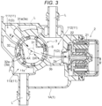
- FIG. 3 is a cross-sectional view illustrating a configuration of one of two valves 3 integrated with the cooling module 100 (a three-way valve on the right side when FIG. 2 is viewed) and a vicinity thereof.
- the cooling module 100 is formed by integrating the manifold 1, the pumps 2, and the valves 3.
- the cooling system A includes two pumps 2, and the two pumps 2 are respectively attached to end portions of the manifold 1 in a longitudinal direction. Note that the two pumps 2 have substantially the same configuration, only except that the two pumps 2 are attached to the manifold 1 at different positions.
- the cooling module 100 includes two valves 3, and the two valves 3 are respectively attached (rotatably accommodated) in valve housings 11s formed in a central portion of the manifold 1.
- Each of the two valves 3 is a multiway valve such as a three-way valve or a four-way valve, and a valve corresponding to the fluid flow path L through which the fluid F flows is used.
- a valve corresponding to the fluid flow path L through which the fluid F flows is used.
- one valve 3 of the two valves 3 (the three-way valve on the right side in FIG. 2 ) will be described as an example.
- the manifold 1 includes a first housing 1A and a second housing 1B.
- the manifold 1 is formed by joining the first housing 1A and the second housing 1B.
- the first housing 1A and the second housing 1B are joined by, for example, welding using a resin as a material.
- the manifold 1 has a box shape (approximately rectangular parallelepiped shape) and includes the fluid flow path L.
- the fluid flow path L is formed inside the manifold 1 by grooves, holes, and the like formed in at least one of the first housing 1A and the second housing 1B.
- auxiliary devices such as the pumps 2 and the valves 3 are fixed to the first housing 1A, and the second housing 1B includes only the fluid flow path L to which the auxiliary devices are not connected and a reservoir space 11U described below.
- the pump 2 is an electric water pump.
- the pump 2 includes an electric motor 21 and an impeller 22.
- the electric motor 21 drives and rotates the impeller 22 by being supplied with electric power.
- the pump 2 includes a suction port 2a for sucking the fluid F and a discharge port (not illustrated) for discharging the fluid F.
- the fluid F is sucked into the pump 2 through the suction port 2a, and is discharged to an outside (fluid flow path L) of the pump 2 via the discharge port by a rotational force (centrifugal force) of the impeller 22.
- the valve 3 is a rotary valve.
- the valve 3 includes a drive source 30, a rotary shaft 31, and a valve body 32.
- the drive source 30 is an actuator or the like, and generates power by being supplied with electric power.
- the rotary shaft 31 receives power from the drive source 30 and rotates about an axis AX.
- the valve body 32 rotates about the rotary shaft 31.
- a direction along the axis AX of the rotation shaft 31 is referred to as a "Z direction”
- a side on which the valve body 32 is disposed with respect to the drive source 30 in the Z direction is referred to as a "first axis side Z1”
- an opposite side thereof is referred to as a "second axis side Z2".
- the cooling module 100 is used with the first axis side Z1 as a "lower side in a vertical direction” and the second axis side Z2 as an "upper side in the vertical direction”.
- FIG. 4 is a cross-sectional view illustrating a configuration of the valve 3 in a posture different from that of FIG. 3 and a vicinity thereof.
- first posture the posture of the valve 3 illustrated in FIG. 3
- second posture the posture of the valve 3 illustrated in FIG. 4
- the valve 3 includes an inflow port 3a through which the fluid F flows in and an outflow port 3b from which the fluid F flows out.
- the inflow port 3a includes a first inflow port 31a through which the fluid F flows into the valve 3 in the first posture illustrated in FIG. 3 , and a second inflow port 32a through which the fluid F flows into the valve 3 in the second posture illustrated in FIG. 4 .
- the fluid F flows out of the valve 3 through the outflow port 3b.
- the valve 3 further includes a seal member S.
- the seal member S is disposed outside the valve body 32 in a radial direction DR.
- the seal member S prevents leakage of the fluid F from the inflow port 3a and the outflow port 3b.
- FIG. 5 is a cross-sectional view taken along a line V-V illustrated in FIG. 3
- FIG. 6 is a cross-sectional view taken along a line VI-VI illustrated in FIG. 4 .
- the manifold 1 includes a foreign matter reservoir 11 that stores foreign matter M such as casting sand, dust, and dirt.
- the foreign matter M is contained, for example, inside the auxiliary devices.
- the casting sand may be generated in the process of producing the auxiliary devices and may remain inside the auxiliary devices.
- the auxiliary devices include the manifold 1, the pump 2, the valve 3, the heater core 4, the electric heater 5, and the water-cooled condenser 6 described with reference to FIG. 1 .
- the foreign matter reservoir 11 is formed between the first housing 1A and the second housing 1B by joining the first housing 1A and the second housing 1B.
- the foreign matter reservoir 11 is a space formed across the first housing 1A and the second housing 1B. That is, the foreign matter reservoir 11 is a space extending along the Z direction (vertical direction).
- the foreign matter reservoir 11 is a space having a flow path cross-sectional area larger than the flow path cross-sectional area of the fluid flow path L (see FIGS. 4 and 6 ).
- the flow path cross-sectional area is an area of a cross section of the fluid flow path, which is obtained by being cut along a direction perpendicular to a direction (flow direction D) in which the main flow of the fluid F flows.
- the foreign matter reservoir 11 is a space having a flow path cross-sectional area larger than the flow path cross-sectional area of the fluid flow path L.
- the foreign matter M has a larger specific gravity than the fluid F, and therefore, when the foreign matter M flows into the foreign matter reservoir 11 together with the fluid F flowing through the fluid flow path L, the foreign matter M is guided (immersed) to the first axis side Z1 (lower side in the vertical direction) due to a difference in specific gravity (own weight).
- the foreign matter M guided to the first axis side Z1 (the lower side in the vertical direction) in the foreign matter reservoir 11 stays in the foreign matter reservoir 11. Accordingly, the flow of the foreign matter M in the fluid flow path L can be prevented.
- the foreign matter reservoir 11 includes a flow portion 11R through which the main flow of the fluid F flows and a stagnation portion 11T in which the fluid F stagnates.
- a split flow different from the main flow of the fluid F (the fluid F having a flow velocity lower than that in the flow portion (11R)) may flow in the stagnation portion 11T.
- the flow portion 11R is a space between a lower end of each of the inflow port 3a of the valve 3 (also see FIG. 6 ), the outflow port 3b of the valve 3, and the suction port 2a of the pump 2 and the second axis side Z2 (upper side in the vertical direction) with respect to the lower ends in the radial direction DR (direction perpendicular to the Z direction).
- the flow portion 11R includes a portion facing any one of the inflow port 3a of the valve 3, the outflow port 3b of the valve 3, and the suction port 2a of the pump 2.
- the stagnation portion 11T is a space disposed on the first axis side Z1 (lower side in the vertical direction) with respect to the flow portion 11R. That is, in the present embodiment, the stagnation portion 11T is a space on the first axis side Z1 (lower side in the vertical direction) with respect to each of the inflow port 3a (also see FIG. 6 ) of the valve 3, the outflow port 3b of the valve 3, and the suction port 2a of the pump 2.
- the stagnation portion 11T includes the reservoir space 11U.
- the reservoir space 11U is disposed on the first axis side Z1 (lower side in the vertical direction) with respect to the valve 3.
- the reservoir space 11U is a space on the first axis side Z1 (lower side in the vertical direction) with respect to a standard line SL along a lower end 3d of the valve 3.
- the reservoir space 11U is formed in the second housing 1B.
- the foreign matter reservoir 11 includes a first reservoir 111, a second reservoir 112, and a third reservoir 113.
- the first reservoir 111, the second reservoir 112, and the third reservoir 113 are disposed around the valve 3.
- the first reservoir 111 is disposed adjacent to the first inflow port 31a of the valve 3
- the second reservoir 112 is disposed adjacent to the outflow port 3b of the valve 3
- the third reservoir 113 is disposed adjacent to the second inflow port 32a of the valve 3.
- the second reservoir 112 is also disposed adjacent to the suction port 2a of the pump 2. That is, the second reservoir 112 is disposed between the valve 3 and the pump 2.
- the first reservoir 111 is disposed upstream of the first inflow port 31a of the valve 3 in the first posture in the flow direction D, and is connected (directly connected) to the first inflow port 31a.
- the flow portion 11R of the first reservoir 111 described with reference to FIG. 5 communicates with the first inflow port 31a of the valve 3 in the first posture (faces the first inflow port 31a in the radial direction DR). Therefore, the fluid F flows through the flow portion 11R of the first reservoir 111 and flows into the valve 3 via the first inflow port 31a.
- the foreign matter M flowing into the first reservoir 111 together with the fluid F is guided to the reservoir space 11U of the first reservoir 111 and stays in the reservoir space 11U.
- the second reservoir 112 is disposed downstream of the outflow port 3b of the valve 3 in the first posture (see FIG. 3 ) and the second posture (see FIG. 4 ) in the flow direction D, and is connected (directly connected) to the outflow port 3b.
- the flow portion 11R of the second reservoir 112 described with reference to FIG. 5 communicates with the outflow port 3b of the valve 3 in the first posture and the second posture (faces the outflow port 3b in the radial direction DR).
- the second reservoir 112 is disposed upstream of the suction port 2a of the pump 2 in the flow direction D, and is connected (directly connected) to the suction port 2a. That is, the flow portion 11R of the second reservoir 112 communicates with the suction port 2a (faces the suction port 2a in the radial direction DR). Therefore, the fluid F flows from the valve 3 into the second reservoir 112 through the outflow port 3b, flows through the flow portion 11R of the second reservoir 112, and is sucked into the pump 2 via the suction port 2a. The foreign matter M flowing into the second reservoir 112 together with the fluid F is guided to the reservoir space 11U of the second reservoir 112 and stays in the reservoir space 11U.
- the third reservoir 113 is disposed upstream of the second inflow port 32a of the valve 3 in the second posture in the flow direction D, and is connected (directly connected) to the second inflow port 32a.
- the flow portion 11R of the third reservoir 113 described with reference to FIG. 6 communicates with the second inflow port 32a of the valve 3 in the second posture (faces the second inflow port 32a in the radial direction DR). Therefore, the fluid F flows through the flow portion 11R of the third reservoir 113 and flows into the valve 3 via the second inflow port 32a.
- the foreign matter M flowing into the third reservoir 113 together with the fluid F is guided to the reservoir space 11U of the third reservoir 113 and stays in the reservoir space 11U.
- the first reservoir 111 and the third reservoir 113 are disposed upstream of the valve 3 in the flow direction D. Therefore, the foreign matter M can be guided (caught) to the reservoir spaces 11U before flowing into the valve 3. Accordingly, the inflow of the foreign matter M into the valve 3 can be prevented.
- the second reservoir 112 is disposed downstream of the valve 3 in the flow direction D. Therefore, the foreign matter M guided to the reservoir space 11U of the second reservoir 112 can be prevented from flowing into the valve 3 with the backflow of the fluid F or against the flow of the fluid F.
- the inflow of the foreign matter M into the valve 3 can be prevented, and therefore, for example, the malfunction of the valve 3 caused by the foreign matter M interposed between the seal member S and the valve body 32 can be prevented.
- damage to the valve body 32, the seal member S, and the like can be prevented, and shortening of the service life of the valve 3 can also be prevented.
- the second reservoir 112 is disposed upstream of the pump 2 in the flow direction D. Therefore, the foreign matter M can be guided (caught) to the reservoir space 11II before flowing into the pump 2. Accordingly, the inflow of the foreign matter M into the pump 2 can be prevented. As a result, for example, the malfunction of the pump 2 caused by the foreign matter M interposed between the electric motor 21 and the impeller 22 can be prevented. In addition, damage to the electric motor 21, the impeller 22, and the like can also be prevented, and shortening of the service life of the pump 2 can also be prevented.
- the reservoir space 11U is disposed on the first axis side Z1 (the lower side in the vertical direction) with respect to the valve 3. Accordingly, the foreign matter M guided to the reservoir space 11U is more reliably prevented from flowing out of the foreign matter reservoir 11 and flowing into the valve 3.
- the reservoir space 11U is disposed on the first axis side Z1 (lower side in the vertical direction) with respect to a lower end 2d of the pump 2. Therefore, the foreign matter M guided to the reservoir space 11U is prevented from flowing out of the foreign matter reservoir 11 and flowing into the pump 2.
- the technique according to the present disclosure can be used for a cooling module.
Landscapes
- Engineering & Computer Science (AREA)
- General Engineering & Computer Science (AREA)
- Mechanical Engineering (AREA)
- Chemical & Material Sciences (AREA)
- General Chemical & Material Sciences (AREA)
- Manufacturing & Machinery (AREA)
- Chemical Kinetics & Catalysis (AREA)
- Electrochemistry (AREA)
- Combustion & Propulsion (AREA)
- Microelectronics & Electronic Packaging (AREA)
- Thermal Sciences (AREA)
- Physics & Mathematics (AREA)
- Transportation (AREA)
- Details Of Reciprocating Pumps (AREA)
- Valve Housings (AREA)
- Multiple-Way Valves (AREA)
Abstract
Description
- This disclosure relates to a cooling module.
- Various techniques for performing thermal management on a thermal management target such as a motor or a battery mounted on a vehicle such as an electric automatic vehicle are disclosed. For example,
CN218367467U (Reference 1) discloses a thermal management water-side integrated assembly that reduces space occupancy, cost, and the like and reduces a risk of water leakage in a pipe line. The thermal management water-side integrated assembly disclosed inReference 1 includes a flow path plate on which a plurality of fluid flow paths are formed, and a plurality of thermal management components such as a pump, which are attached to the flow path plate and connected to the fluid flow paths. In addition, a plurality of pipe line external connection interfaces are formed in the flow path plate and are connected to a temperature control loop of a heat management target such as a battery. - In the thermal management water side integrated assembly disclosed in
Reference 1, for example, foreign matter contained in a component connected to the pipe line external connection interface may flow through the fluid flow path together with a fluid to cause malfunction of a thermal management component. - A need thus exists for a cooling module that restricts the flow of foreign matter in a fluid flow path.
- According to an aspect of this disclosure, a cooling module includes a manifold to which a valve configured to control flow of a fluid is attached and in which a fluid flow path configured to allow the fluid to flow therethrough is formed. The manifold includes a foreign matter reservoir having a flow path cross-sectional area larger than a flow path cross-sectional area of the fluid flow path and storing a foreign matter flowing through the fluid flow path. The foreign matter reservoir is connected to at least one of an inflow port configured to allow the fluid to flow therethrough into the valve and an outflow port configured to allow the fluid to flow therethrough out of the valve.
- According to such a characteristic configuration, the manifold includes the foreign matter reservoir that stores the foreign matter flowing through the fluid flow path, and therefore, the flow of the foreign matter in the fluid flow path can be prevented. The foreign matter reservoir is connected to at least one of the inflow port of the valve and the outflow port of the valve, and therefore, the inflow of the foreign matter into the valve can also be prevented.
- The foregoing and additional features and characteristics of this disclosure will become more apparent from the following detailed description considered with the reference to the accompanying drawings, wherein:
-
FIG. 1 is a diagram illustrating a part of a cooling circuit of a cooling system according to an embodiment; -
FIG. 2 is an exploded perspective view illustrating a configuration of a cooling module according to the embodiment; -
FIG. 3 is a cross-sectional view illustrating a configuration of a valve and a vicinity thereof illustrated inFIG. 2 ; -
FIG. 4 is a cross-sectional view illustrating a configuration of the valve in a posture different from that ofFIG. 3 and a vicinity thereof; -
FIG. 5 is a cross-sectional view taken along a line V-V illustrated inFIG. 3 ; and -
FIG. 6 is a cross-sectional view taken along a line VI-VI illustrated inFIG. 4 . - Hereinafter, embodiments of a cooling module according to this disclosure will be described with reference to the drawings. However, this disclosure is not limited to the following embodiments, and various modifications can be made without departing from the gist of this disclosure.
- First, a cooling system A including a
cooling module 100 will be described with reference toFIG. 1. FIG. 1 is a diagram illustrating a part of a cooling circuit of the cooling system A. - The
cooling module 100 is mounted on an electric vehicle that travels by electric power. Examples of the electric vehicle include a hybrid electric vehicle (HEV), a plug-in hybrid electric vehicle (PHEV), a battery electric vehicle (BEV), and a fuel cell electric vehicle (FCEV). - The cooling system A cools (performs temperature management of) a cooling target device (temperature management target device) (not illustrated) mounted on an electric vehicle. The cooling target device includes an inverter/motor as a traveling drive source that operates by being supplied with power, a battery that stores electric power, and the like. The electric power stored in the battery is supplied to the inverter/motor.
- As illustrated in
FIG. 1 , the cooling system A includes a fluid flow path L through which a fluid F for cooling a cooling target device flows. The fluid F is a cooling fluid such as a long life coolant (LLC). In this case, the fluid F is not limited to a cooling fluid such as a long life coolant (LLC), and may be a refrigerant such as an insulating oil, for example, a paraffin-based oil, a hydrofluorocarbon (HFC), and a hydrofluoroolefin (HFO). - The cooling system A further includes a
manifold 1, apump 2, avalve 3, aheater core 4, anelectric heater 5, and a water-cooledcondenser 6. Themanifold 1, thepump 2, thevalve 3, theheater core 4, theelectric heater 5, and the water-cooledcondenser 6 are connected to the cooling target device via the fluid flow path L. - The
pump 2 pressure-feeds the fluid F. Thevalve 3 controls the flow of the fluid F. Theheater core 4 heats the air with the fluid F to increase the temperature inside a vehicle interior. Theelectric heater 5 heats the fluid F in the case where the temperature of the fluid F is lower than a preset temperature. The water-cooledcondenser 6 cools the fluid F in the case where the temperature of the fluid F is higher than the preset temperature. The cooling target device is cooled by the fluid F flowing through the fluid flow path L. Hereinafter, a direction in which the fluid F flows through the fluid flow path L is referred to as a "flow direction D". - Next, the
cooling module 100 forming a part of the cooling system A will be described with reference toFIGS. 2 and3 .FIG. 2 is an exploded perspective view illustrating a configuration of thecooling module 100.FIG. 3 is a cross-sectional view illustrating a configuration of one of twovalves 3 integrated with the cooling module 100 (a three-way valve on the right side whenFIG. 2 is viewed) and a vicinity thereof. - As illustrated in
FIG. 2 , thecooling module 100 is formed by integrating themanifold 1, thepumps 2, and thevalves 3. In the present embodiment, the cooling system A includes twopumps 2, and the twopumps 2 are respectively attached to end portions of themanifold 1 in a longitudinal direction. Note that the twopumps 2 have substantially the same configuration, only except that the twopumps 2 are attached to themanifold 1 at different positions. In the present embodiment, thecooling module 100 includes twovalves 3, and the twovalves 3 are respectively attached (rotatably accommodated) invalve housings 11s formed in a central portion of themanifold 1. Each of the twovalves 3 is a multiway valve such as a three-way valve or a four-way valve, and a valve corresponding to the fluid flow path L through which the fluid F flows is used. Hereinafter, onevalve 3 of the two valves 3 (the three-way valve on the right side inFIG. 2 ) will be described as an example. - The
manifold 1 includes afirst housing 1A and asecond housing 1B. Themanifold 1 is formed by joining thefirst housing 1A and thesecond housing 1B. Thefirst housing 1A and thesecond housing 1B are joined by, for example, welding using a resin as a material. - The
manifold 1 has a box shape (approximately rectangular parallelepiped shape) and includes the fluid flow path L. The fluid flow path L is formed inside themanifold 1 by grooves, holes, and the like formed in at least one of thefirst housing 1A and thesecond housing 1B. In themanifold 1 according to the present embodiment, auxiliary devices such as thepumps 2 and thevalves 3 are fixed to thefirst housing 1A, and thesecond housing 1B includes only the fluid flow path L to which the auxiliary devices are not connected and areservoir space 11U described below. - As illustrated in
FIG. 3 , thepump 2 is an electric water pump. Thepump 2 includes anelectric motor 21 and animpeller 22. Theelectric motor 21 drives and rotates theimpeller 22 by being supplied with electric power. - The
pump 2 includes asuction port 2a for sucking the fluid F and a discharge port (not illustrated) for discharging the fluid F. The fluid F is sucked into thepump 2 through thesuction port 2a, and is discharged to an outside (fluid flow path L) of thepump 2 via the discharge port by a rotational force (centrifugal force) of theimpeller 22. - As illustrated in
FIG. 2 , thevalve 3 is a rotary valve. Thevalve 3 includes adrive source 30, arotary shaft 31, and avalve body 32. Thedrive source 30 is an actuator or the like, and generates power by being supplied with electric power. Therotary shaft 31 receives power from thedrive source 30 and rotates about an axis AX. Thevalve body 32 rotates about therotary shaft 31. Hereinafter, a direction along the axis AX of therotation shaft 31 is referred to as a "Z direction", a side on which thevalve body 32 is disposed with respect to thedrive source 30 in the Z direction is referred to as a "first axis side Z1", and an opposite side thereof is referred to as a "second axis side Z2". In the present embodiment, thecooling module 100 is used with the first axis side Z1 as a "lower side in a vertical direction" and the second axis side Z2 as an "upper side in the vertical direction". - As shown in
FIGS. 3 and4 , thevalve 3 controls the flow of the fluid F by rotating thevalve body 32 together with therotation shaft 31.FIG. 4 is a cross-sectional view illustrating a configuration of thevalve 3 in a posture different from that ofFIG. 3 and a vicinity thereof. Hereinafter, the posture of thevalve 3 illustrated inFIG. 3 is referred to as a "first posture", and the posture of thevalve 3 illustrated inFIG. 4 is referred to as a "second posture". - The
valve 3 includes aninflow port 3a through which the fluid F flows in and anoutflow port 3b from which the fluid F flows out. Theinflow port 3a includes afirst inflow port 31a through which the fluid F flows into thevalve 3 in the first posture illustrated inFIG. 3 , and asecond inflow port 32a through which the fluid F flows into thevalve 3 in the second posture illustrated inFIG. 4 . In thevalve 3 in the first posture and the second posture, the fluid F flows out of thevalve 3 through theoutflow port 3b. - The
valve 3 further includes a seal member S. The seal member S is disposed outside thevalve body 32 in a radial direction DR. The seal member S prevents leakage of the fluid F from theinflow port 3a and theoutflow port 3b. - Next, a configuration of the
manifold 1 will be described in detail with reference toFIGS. 3 to 6 .FIG. 5 is a cross-sectional view taken along a line V-V illustrated inFIG. 3 , andFIG. 6 is a cross-sectional view taken along a line VI-VI illustrated inFIG. 4 . - As illustrated in
FIGS. 3 to 6 , themanifold 1 includes aforeign matter reservoir 11 that stores foreign matter M such as casting sand, dust, and dirt. The foreign matter M is contained, for example, inside the auxiliary devices. In particular, the casting sand may be generated in the process of producing the auxiliary devices and may remain inside the auxiliary devices. When the auxiliary devices including the foreign matter M are connected to the fluid flow path L and the fluid F flows through the auxiliary devices, the foreign matter M flows through the fluid flow path L. The auxiliary devices include themanifold 1, thepump 2, thevalve 3, theheater core 4, theelectric heater 5, and the water-cooledcondenser 6 described with reference toFIG. 1 . - As shown in
FIGS. 5 and6 , theforeign matter reservoir 11 is formed between thefirst housing 1A and thesecond housing 1B by joining thefirst housing 1A and thesecond housing 1B. Theforeign matter reservoir 11 is a space formed across thefirst housing 1A and thesecond housing 1B. That is, theforeign matter reservoir 11 is a space extending along the Z direction (vertical direction). Theforeign matter reservoir 11 is a space having a flow path cross-sectional area larger than the flow path cross-sectional area of the fluid flow path L (seeFIGS. 4 and6 ). The flow path cross-sectional area is an area of a cross section of the fluid flow path, which is obtained by being cut along a direction perpendicular to a direction (flow direction D) in which the main flow of the fluid F flows. - As described above, the
foreign matter reservoir 11 is a space having a flow path cross-sectional area larger than the flow path cross-sectional area of the fluid flow path L. In the present embodiment, the foreign matter M has a larger specific gravity than the fluid F, and therefore, when the foreign matter M flows into theforeign matter reservoir 11 together with the fluid F flowing through the fluid flow path L, the foreign matter M is guided (immersed) to the first axis side Z1 (lower side in the vertical direction) due to a difference in specific gravity (own weight). - The foreign matter M guided to the first axis side Z1 (the lower side in the vertical direction) in the
foreign matter reservoir 11 stays in theforeign matter reservoir 11. Accordingly, the flow of the foreign matter M in the fluid flow path L can be prevented. - The
foreign matter reservoir 11 includes aflow portion 11R through which the main flow of the fluid F flows and astagnation portion 11T in which the fluid F stagnates. A split flow different from the main flow of the fluid F (the fluid F having a flow velocity lower than that in the flow portion (11R)) may flow in thestagnation portion 11T. - The
flow portion 11R is a space between a lower end of each of theinflow port 3a of the valve 3 (also seeFIG. 6 ), theoutflow port 3b of thevalve 3, and thesuction port 2a of thepump 2 and the second axis side Z2 (upper side in the vertical direction) with respect to the lower ends in the radial direction DR (direction perpendicular to the Z direction). Theflow portion 11R includes a portion facing any one of theinflow port 3a of thevalve 3, theoutflow port 3b of thevalve 3, and thesuction port 2a of thepump 2. - The
stagnation portion 11T is a space disposed on the first axis side Z1 (lower side in the vertical direction) with respect to theflow portion 11R. That is, in the present embodiment, thestagnation portion 11T is a space on the first axis side Z1 (lower side in the vertical direction) with respect to each of theinflow port 3a (also seeFIG. 6 ) of thevalve 3, theoutflow port 3b of thevalve 3, and thesuction port 2a of thepump 2. - In the present embodiment, the
stagnation portion 11T includes thereservoir space 11U. Thereservoir space 11U is disposed on the first axis side Z1 (lower side in the vertical direction) with respect to thevalve 3. Specifically, thereservoir space 11U is a space on the first axis side Z1 (lower side in the vertical direction) with respect to a standard line SL along alower end 3d of thevalve 3. In the present embodiment, thereservoir space 11U is formed in thesecond housing 1B. - In the present embodiment, as shown in
FIGS. 3 and4 , theforeign matter reservoir 11 includes afirst reservoir 111, asecond reservoir 112, and athird reservoir 113. Thefirst reservoir 111, thesecond reservoir 112, and thethird reservoir 113 are disposed around thevalve 3. Specifically, thefirst reservoir 111 is disposed adjacent to thefirst inflow port 31a of thevalve 3, thesecond reservoir 112 is disposed adjacent to theoutflow port 3b of thevalve 3, and thethird reservoir 113 is disposed adjacent to thesecond inflow port 32a of thevalve 3. Thesecond reservoir 112 is also disposed adjacent to thesuction port 2a of thepump 2. That is, thesecond reservoir 112 is disposed between thevalve 3 and thepump 2. - As shown in
FIG. 3 , thefirst reservoir 111 is disposed upstream of thefirst inflow port 31a of thevalve 3 in the first posture in the flow direction D, and is connected (directly connected) to thefirst inflow port 31a. Theflow portion 11R of thefirst reservoir 111 described with reference toFIG. 5 communicates with thefirst inflow port 31a of thevalve 3 in the first posture (faces thefirst inflow port 31a in the radial direction DR). Therefore, the fluid F flows through theflow portion 11R of thefirst reservoir 111 and flows into thevalve 3 via thefirst inflow port 31a. The foreign matter M flowing into thefirst reservoir 111 together with the fluid F is guided to thereservoir space 11U of thefirst reservoir 111 and stays in thereservoir space 11U. - The
second reservoir 112 is disposed downstream of theoutflow port 3b of thevalve 3 in the first posture (seeFIG. 3 ) and the second posture (seeFIG. 4 ) in the flow direction D, and is connected (directly connected) to theoutflow port 3b. Theflow portion 11R of thesecond reservoir 112 described with reference toFIG. 5 communicates with theoutflow port 3b of thevalve 3 in the first posture and the second posture (faces theoutflow port 3b in the radial direction DR). - The
second reservoir 112 is disposed upstream of thesuction port 2a of thepump 2 in the flow direction D, and is connected (directly connected) to thesuction port 2a. That is, theflow portion 11R of thesecond reservoir 112 communicates with thesuction port 2a (faces thesuction port 2a in the radial direction DR). Therefore, the fluid F flows from thevalve 3 into thesecond reservoir 112 through theoutflow port 3b, flows through theflow portion 11R of thesecond reservoir 112, and is sucked into thepump 2 via thesuction port 2a. The foreign matter M flowing into thesecond reservoir 112 together with the fluid F is guided to thereservoir space 11U of thesecond reservoir 112 and stays in thereservoir space 11U. - As illustrated in
FIG. 4 , thethird reservoir 113 is disposed upstream of thesecond inflow port 32a of thevalve 3 in the second posture in the flow direction D, and is connected (directly connected) to thesecond inflow port 32a. Theflow portion 11R of thethird reservoir 113 described with reference toFIG. 6 communicates with thesecond inflow port 32a of thevalve 3 in the second posture (faces thesecond inflow port 32a in the radial direction DR). Therefore, the fluid F flows through theflow portion 11R of thethird reservoir 113 and flows into thevalve 3 via thesecond inflow port 32a. The foreign matter M flowing into thethird reservoir 113 together with the fluid F is guided to thereservoir space 11U of thethird reservoir 113 and stays in thereservoir space 11U. - As described above, the
first reservoir 111 and thethird reservoir 113 are disposed upstream of thevalve 3 in the flow direction D. Therefore, the foreign matter M can be guided (caught) to thereservoir spaces 11U before flowing into thevalve 3. Accordingly, the inflow of the foreign matter M into thevalve 3 can be prevented. Thesecond reservoir 112 is disposed downstream of thevalve 3 in the flow direction D. Therefore, the foreign matter M guided to thereservoir space 11U of thesecond reservoir 112 can be prevented from flowing into thevalve 3 with the backflow of the fluid F or against the flow of the fluid F. The inflow of the foreign matter M into thevalve 3 can be prevented, and therefore, for example, the malfunction of thevalve 3 caused by the foreign matter M interposed between the seal member S and thevalve body 32 can be prevented. In addition, damage to thevalve body 32, the seal member S, and the like can be prevented, and shortening of the service life of thevalve 3 can also be prevented. - The
second reservoir 112 is disposed upstream of thepump 2 in the flow direction D. Therefore, the foreign matter M can be guided (caught) to the reservoir space 11II before flowing into thepump 2. Accordingly, the inflow of the foreign matter M into thepump 2 can be prevented. As a result, for example, the malfunction of thepump 2 caused by the foreign matter M interposed between theelectric motor 21 and theimpeller 22 can be prevented. In addition, damage to theelectric motor 21, theimpeller 22, and the like can also be prevented, and shortening of the service life of thepump 2 can also be prevented. - As described with reference to
FIGS. 5 and6 , thereservoir space 11U is disposed on the first axis side Z1 (the lower side in the vertical direction) with respect to thevalve 3. Accordingly, the foreign matter M guided to thereservoir space 11U is more reliably prevented from flowing out of theforeign matter reservoir 11 and flowing into thevalve 3. In the present embodiment, thereservoir space 11U is disposed on the first axis side Z1 (lower side in the vertical direction) with respect to alower end 2d of thepump 2. Therefore, the foreign matter M guided to thereservoir space 11U is prevented from flowing out of theforeign matter reservoir 11 and flowing into thepump 2. - In the above-described embodiment, the following configurations are considered.
- (1) A
cooling module 100 includes amanifold 1 to which avalve 3 configured to control flow of a fluid F is attached and in which a fluid flow path L configured to allow the fluid F to flow therethrough is formed. Themanifold 1 includes aforeign matter reservoir 11 having a flow path cross-sectional area larger than a flow path cross-sectional area of the fluid flow path L and storing a foreign matter M flowing through the fluid flow path L. Theforeign matter reservoir 11 is connected to at least one of aninflow port 3a configured to allow the fluid F to flow therethrough into thevalve 3 and anoutflow port 3b configured to allow the fluid F to flow out of thevalve 3.
According to this configuration, themanifold 1 includes theforeign matter reservoir 11 that stores the foreign matter M flowing through the fluid flow path L, and therefore, the flow of the foreign matter M in the fluid flow path L can be prevented. Theforeign matter reservoir 11 is connected to at least one of theinflow port 3a of thevalve 3 and theoutflow port 3b of thevalve 3, and therefore, the foreign matter M is prevented from flowing into thevalve 3. - (2) In the
cooling module 100 according to (1), it is preferable that theforeign matter reservoir 11 is connected to asuction port 2a through which the fluid F is sucked into apump 2 configured to pressure-feed the fluid F.
According to this configuration, theforeign matter reservoir 11 is connected to thesuction port 2a of thepump 2. In other words, theforeign matter reservoir 11 is disposed upstream of thepump 2 in the flow direction D of the fluid F. Therefore, the inflow of the foreign matter M into thepump 2 is prevented. - (3) In the
cooling module 100 according to (1) or (2), it is preferable that themanifold 1 includes afirst housing 1A and asecond housing 1B joined to thefirst housing 1A, and theforeign matter reservoir 11 is formed between thefirst housing 1A and thesecond housing 1B.
According to this configuration, theforeign matter reservoir 11 is formed between thefirst housing 1A and thesecond housing 1B which are separate components. Therefore, theforeign matter reservoir 11 can be easily provided. - (4) In the
cooling module 100 according to (3), it is preferable that theforeign matter reservoir 11 has areservoir space 11U on a lower side in a vertical direction with respect to thevalve 3.
According to this configuration, theforeign matter reservoir 11 has the reservoir space 11II on the lower side in the vertical direction with respect to thevalve 3, and therefore, the foreign matter M can be more reliably prevented from flowing into thevalve 3. - Next, other embodiments of the cooling module will be described.
- (a) The principles, preferred embodiment and mode of operation of the present invention have been described in the foregoing specification. However, the invention which is intended to be protected is not to be construed as limited to the particular embodiments disclosed. Further, the embodiments described herein are to be regarded as illustrative rather than restrictive. Variations and changes may be made by others, and equivalents employed, without departing from the spirit of the present invention. Accordingly, it is expressly intended that all such variations, changes and equivalents which fall within the spirit and scope of the present invention as defined in the claims, be embraced thereby.
- (b) The
foreign matter reservoir 11 may also be disposed at a position other than the periphery of thevalve 3 so as to efficiently catch the foreign matter M flowing through the fluid flow path L. - (c) In the above-described embodiment, the
foreign matter reservoir 11 includes thefirst reservoir 111, thesecond reservoir 112, and thethird reservoir 113, thefirst reservoir 111 and thethird reservoir 113 are connected to theinflow port 3a of thevalve 3, and thesecond reservoir 112 is connected to theoutflow port 3b of thevalve 3. However, theforeign matter reservoir 11 may be connected to at least one of theinflow port 3a and theoutflow port 3b of thevalve 3. That is, theforeign matter reservoir 11 may include, for example, only at least one of thefirst reservoir 111 and thethird reservoir 113 that are connected to theinflow port 3a, or only thesecond reservoir 112 connected to theoutflow port 3b. - (d) The
second reservoir 112 is connected to thesuction port 2a of thepump 2 in the above-described embodiment, and thesecond reservoir 112 may not be connected to thesuction port 2a of thepump 2. Thesecond reservoir 112 may be connected to a discharge port of thepump 2. - (e) In the above-described embodiment, the
first reservoir 111 and thethird reservoir 113 are directly connected to theinflow port 3a of thevalve 3, and thesecond reservoir 112 is directly connected to theoutflow port 3b of thevalve 3 and thesuction port 2a of thepump 2. Note that "direct connection" refers to a configuration in which connection is performed without a gap. Specifically, a gap is not provided between thefirst reservoir 111 and thefirst inflow port 31a of thevalve 3, and thefirst reservoir 111 and thefirst inflow port 31a of thevalve 3 are connected with each other. The same applies to the space between thethird reservoir 113 and thesecond inflow port 32a of thevalve 3, the space between thesecond reservoir 112 and theoutflow port 3b, and the space between thesecond reservoir 112 and thesuction port 2a of thepump 2. In this case, for example, the fluid flow path L may be interposed between at least one of thefirst reservoir 111 and thethird reservoir 113 and theinflow port 3a of thevalve 3. Similarly, for example, the fluid flow path L may be interposed between thesecond reservoir 112 and at least one of theoutflow port 3b of thevalve 3 and thesuction port 2a of thepump 2. - (f) The
reservoir space 11U of theforeign matter reservoir 11 may be omitted. - (g) The cooling system A includes devices (for example, a radiator, a chiller, a DC-DC converter, and a charger) other than the
manifold 1, thepump 2, thevalve 3, theheater core 4, theelectric heater 5, and the water-cooledcondenser 6, and these devices may be connected to the fluid flow path L. - The technique according to the present disclosure can be used for a cooling module.
Claims (4)
- A cooling module (100) comprising:a manifold (1) to which a valve (3) configured to control flow of a fluid (F) is attached and in which a fluid flow path (L) configured to allow the fluid to flow therethrough is formed, whereinthe manifold includes a foreign matter reservoir (11) having a flow path cross-sectional area larger than a flow path cross-sectional area of the fluid flow path and storing a foreign matter (M) flowing through the fluid flow path, andthe foreign matter reservoir is connected to at least one of an inflow port (3a) configured to allow the fluid to flow therethrough into the valve and an outflow port (3b) configured to allow the fluid to flow therethrough out of the valve.
- The cooling module according to claim 1, wherein
the foreign matter reservoir is connected to a suction port (2a) through which the fluid is sucked into a pump (2) configured to pressure-feed the fluid. - The cooling module according to claim 1 or 2, whereinthe manifold includes a first housing (1A) and a second housing (1B) joined to the first housing, andthe foreign matter reservoir is formed between the first housing and the second housing.
- The cooling module according to claim 3, wherein
the foreign matter reservoir has a reservoir space (11U) on a lower side in a vertical direction with respect to the valve.
Applications Claiming Priority (1)
| Application Number | Priority Date | Filing Date | Title |
|---|---|---|---|
| JP2023114655A JP2025012089A (en) | 2023-07-12 | 2023-07-12 | Cooling Module |
Publications (2)
| Publication Number | Publication Date |
|---|---|
| EP4495399A1 true EP4495399A1 (en) | 2025-01-22 |
| EP4495399B1 EP4495399B1 (en) | 2026-04-29 |
Family
ID=91664986
Family Applications (1)
| Application Number | Title | Priority Date | Filing Date |
|---|---|---|---|
| EP24184056.0A Active EP4495399B1 (en) | 2023-07-12 | 2024-06-24 | Cooling module |
Country Status (4)
| Country | Link |
|---|---|
| US (1) | US20250020229A1 (en) |
| EP (1) | EP4495399B1 (en) |
| JP (1) | JP2025012089A (en) |
| CN (1) | CN119315165A (en) |
Families Citing this family (1)
| Publication number | Priority date | Publication date | Assignee | Title |
|---|---|---|---|---|
| US12650121B2 (en) * | 2024-09-24 | 2026-06-09 | GM Global Technology Operations LLC | Swappable integrated coolant module |
Citations (5)
| Publication number | Priority date | Publication date | Assignee | Title |
|---|---|---|---|---|
| US4254793A (en) * | 1979-01-15 | 1981-03-10 | Domer Scaramucci | Ball valve having valve chamber venting seal assemblies |
| JP5247277B2 (en) * | 2008-07-17 | 2013-07-24 | 株式会社藤井合金製作所 | Gas stopper |
| JP7178548B2 (en) * | 2018-07-31 | 2022-11-28 | パナソニックIpマネジメント株式会社 | electric pump |
| CN218367467U (en) | 2022-11-09 | 2023-01-24 | 广东美芝制冷设备有限公司 | Heat management water side integrated assembly, heat management integrated system and electric vehicle |
| WO2023112738A1 (en) * | 2021-12-13 | 2023-06-22 | 株式会社山田製作所 | Control valve |
-
2023
- 2023-07-12 JP JP2023114655A patent/JP2025012089A/en active Pending
-
2024
- 2024-06-24 US US18/752,043 patent/US20250020229A1/en active Pending
- 2024-06-24 EP EP24184056.0A patent/EP4495399B1/en active Active
- 2024-07-12 CN CN202410932866.XA patent/CN119315165A/en active Pending
Patent Citations (5)
| Publication number | Priority date | Publication date | Assignee | Title |
|---|---|---|---|---|
| US4254793A (en) * | 1979-01-15 | 1981-03-10 | Domer Scaramucci | Ball valve having valve chamber venting seal assemblies |
| JP5247277B2 (en) * | 2008-07-17 | 2013-07-24 | 株式会社藤井合金製作所 | Gas stopper |
| JP7178548B2 (en) * | 2018-07-31 | 2022-11-28 | パナソニックIpマネジメント株式会社 | electric pump |
| WO2023112738A1 (en) * | 2021-12-13 | 2023-06-22 | 株式会社山田製作所 | Control valve |
| CN218367467U (en) | 2022-11-09 | 2023-01-24 | 广东美芝制冷设备有限公司 | Heat management water side integrated assembly, heat management integrated system and electric vehicle |
Also Published As
| Publication number | Publication date |
|---|---|
| EP4495399B1 (en) | 2026-04-29 |
| US20250020229A1 (en) | 2025-01-16 |
| CN119315165A (en) | 2025-01-14 |
| JP2025012089A (en) | 2025-01-24 |
Similar Documents
| Publication | Publication Date | Title |
|---|---|---|
| JP7755678B2 (en) | Integrated Drive System | |
| CN212979863U (en) | Cooling water comprehensive heat management device for vehicle | |
| US20250222760A1 (en) | Cooling module | |
| KR102563579B1 (en) | Electric oil pump system | |
| CN210669779U (en) | Motor unit | |
| EP4495399B1 (en) | Cooling module | |
| CN111063960A (en) | Battery cooling system | |
| CN112140870B (en) | Cooling structure of vehicle | |
| CN119329287A (en) | Cooling system for a drive device of a hybrid vehicle or an electric vehicle and a drive device having such a cooling system | |
| KR20190121450A (en) | Electric oil pump system integrated with heat exchanger | |
| CN116209591A (en) | Vehicles and Battery Packs | |
| EP4491883A1 (en) | Cooling module | |
| US12627195B2 (en) | Drive apparatus | |
| KR101913597B1 (en) | Motor for electric vehicles | |
| CN111602285B (en) | Protective housing for battery pack with integrated channels for transporting heat transfer fluid | |
| JP7447623B2 (en) | motor unit | |
| CN119654775A (en) | Drive device | |
| JP6530619B2 (en) | Control device for construction machine and construction machine provided with the same | |
| JP7622677B2 (en) | Oil cooler | |
| EP4491919A1 (en) | Cooling module | |
| US20260132735A1 (en) | Cooling module | |
| JP2024110009A (en) | Motor generator device | |
| CN121871367A (en) | Cooling module |
Legal Events
| Date | Code | Title | Description |
|---|---|---|---|
| PUAI | Public reference made under article 153(3) epc to a published international application that has entered the european phase |
Free format text: ORIGINAL CODE: 0009012 |
|
| STAA | Information on the status of an ep patent application or granted ep patent |
Free format text: STATUS: THE APPLICATION HAS BEEN PUBLISHED |
|
| AK | Designated contracting states |
Kind code of ref document: A1 Designated state(s): AL AT BE BG CH CY CZ DE DK EE ES FI FR GB GR HR HU IE IS IT LI LT LU LV MC ME MK MT NL NO PL PT RO RS SE SI SK SM TR |
|
| STAA | Information on the status of an ep patent application or granted ep patent |
Free format text: STATUS: REQUEST FOR EXAMINATION WAS MADE |
|
| 17P | Request for examination filed |
Effective date: 20250714 |
|
| GRAP | Despatch of communication of intention to grant a patent |
Free format text: ORIGINAL CODE: EPIDOSNIGR1 |
|
| STAA | Information on the status of an ep patent application or granted ep patent |
Free format text: STATUS: GRANT OF PATENT IS INTENDED |
|
| RIC1 | Information provided on ipc code assigned before grant |
Ipc: F01P 3/12 20060101AFI20251121BHEP Ipc: B60K 11/02 20060101ALI20251121BHEP Ipc: F01P 7/16 20060101ALI20251121BHEP Ipc: F01P 11/04 20060101ALI20251121BHEP Ipc: F16K 11/085 20060101ALI20251121BHEP Ipc: H01M 10/60 20140101ALI20251121BHEP Ipc: F16K 11/083 20060101ALI20251121BHEP Ipc: F16K 11/22 20060101ALI20251121BHEP Ipc: F16K 27/00 20060101ALI20251121BHEP Ipc: B60K 1/00 20060101ALN20251121BHEP Ipc: F01P 7/14 20060101ALN20251121BHEP |
|
| INTG | Intention to grant announced |
Effective date: 20251203 |
|
| RAP3 | Party data changed (applicant data changed or rights of an application transferred) |
Owner name: AISIN CORPORATION |
|
| RIN1 | Information on inventor provided before grant (corrected) |
Inventor name: ISHII, MASATO Inventor name: YANO, HIDETO |
|
| GRAS | Grant fee paid |
Free format text: ORIGINAL CODE: EPIDOSNIGR3 |
|
| GRAA | (expected) grant |
Free format text: ORIGINAL CODE: 0009210 |
|
| STAA | Information on the status of an ep patent application or granted ep patent |
Free format text: STATUS: THE PATENT HAS BEEN GRANTED |
|
| AK | Designated contracting states |
Kind code of ref document: B1 Designated state(s): AL AT BE BG CH CY CZ DE DK EE ES FI FR GB GR HR HU IE IS IT LI LT LU LV MC ME MK MT NL NO PL PT RO RS SE SI SK SM TR |
|
| RAP3 | Party data changed (applicant data changed or rights of an application transferred) |
Owner name: AISIN CORPORATION |
|
| REG | Reference to a national code |
Ref country code: CH Ref legal event code: F10 Free format text: ST27 STATUS EVENT CODE: U-0-0-F10-F00 (AS PROVIDED BY THE NATIONAL OFFICE) Effective date: 20260429 Ref country code: GB Ref legal event code: FG4D |
|
| RIN1 | Information on inventor provided before grant (corrected) |
Inventor name: ISHII, MASATO Inventor name: YANO, HIDETO |
|
| REG | Reference to a national code |
Ref country code: DE Ref legal event code: R096 Ref document number: 602024004338 Country of ref document: DE |
|
| REG | Reference to a national code |
Ref country code: IE Ref legal event code: FG4D |
|
| PGFP | Annual fee paid to national office [announced via postgrant information from national office to epo] |
Ref country code: DE Payment date: 20260522 Year of fee payment: 3 |
|
| PGFP | Annual fee paid to national office [announced via postgrant information from national office to epo] |
Ref country code: AT Payment date: 20260714 Year of fee payment: 3 |
|
| PGFP | Annual fee paid to national office [announced via postgrant information from national office to epo] |
Ref country code: FR Payment date: 20260521 Year of fee payment: 3 |