EP4495396A1 - Method of backpressure testing manufactured parts - Google Patents
Method of backpressure testing manufactured parts Download PDFInfo
- Publication number
- EP4495396A1 EP4495396A1 EP24189623.2A EP24189623A EP4495396A1 EP 4495396 A1 EP4495396 A1 EP 4495396A1 EP 24189623 A EP24189623 A EP 24189623A EP 4495396 A1 EP4495396 A1 EP 4495396A1
- Authority
- EP
- European Patent Office
- Prior art keywords
- backpressure
- testing
- limit
- parts
- manufactured
- Prior art date
- Legal status (The legal status is an assumption and is not a legal conclusion. Google has not performed a legal analysis and makes no representation as to the accuracy of the status listed.)
- Granted
Links
Images




Classifications
-
- F—MECHANICAL ENGINEERING; LIGHTING; HEATING; WEAPONS; BLASTING
- F01—MACHINES OR ENGINES IN GENERAL; ENGINE PLANTS IN GENERAL; STEAM ENGINES
- F01N—GAS-FLOW SILENCERS OR EXHAUST APPARATUS FOR MACHINES OR ENGINES IN GENERAL; GAS-FLOW SILENCERS OR EXHAUST APPARATUS FOR INTERNAL-COMBUSTION ENGINES
- F01N9/00—Electrical control of exhaust gas treating apparatus
-
- F—MECHANICAL ENGINEERING; LIGHTING; HEATING; WEAPONS; BLASTING
- F01—MACHINES OR ENGINES IN GENERAL; ENGINE PLANTS IN GENERAL; STEAM ENGINES
- F01N—GAS-FLOW SILENCERS OR EXHAUST APPARATUS FOR MACHINES OR ENGINES IN GENERAL; GAS-FLOW SILENCERS OR EXHAUST APPARATUS FOR INTERNAL-COMBUSTION ENGINES
- F01N3/00—Exhaust or silencing apparatus having means for purifying, rendering innocuous, or otherwise treating exhaust
- F01N3/08—Exhaust or silencing apparatus having means for purifying, rendering innocuous, or otherwise treating exhaust for rendering innocuous
- F01N3/10—Exhaust or silencing apparatus having means for purifying, rendering innocuous, or otherwise treating exhaust for rendering innocuous by thermal or catalytic conversion of noxious components of exhaust
- F01N3/24—Exhaust or silencing apparatus having means for purifying, rendering innocuous, or otherwise treating exhaust for rendering innocuous by thermal or catalytic conversion of noxious components of exhaust characterised by constructional aspects of converting apparatus
- F01N3/28—Construction of catalytic reactors
- F01N3/2892—Exhaust flow directors or the like, e.g. upstream of catalytic device
-
- G—PHYSICS
- G01—MEASURING; TESTING
- G01N—INVESTIGATING OR ANALYSING MATERIALS BY DETERMINING THEIR CHEMICAL OR PHYSICAL PROPERTIES
- G01N3/00—Investigating strength properties of solid materials by application of mechanical stress
- G01N3/08—Investigating strength properties of solid materials by application of mechanical stress by applying steady tensile or compressive forces
- G01N3/10—Investigating strength properties of solid materials by application of mechanical stress by applying steady tensile or compressive forces generated by pneumatic or hydraulic pressure
- G01N3/12—Pressure testing
-
- F—MECHANICAL ENGINEERING; LIGHTING; HEATING; WEAPONS; BLASTING
- F01—MACHINES OR ENGINES IN GENERAL; ENGINE PLANTS IN GENERAL; STEAM ENGINES
- F01N—GAS-FLOW SILENCERS OR EXHAUST APPARATUS FOR MACHINES OR ENGINES IN GENERAL; GAS-FLOW SILENCERS OR EXHAUST APPARATUS FOR INTERNAL-COMBUSTION ENGINES
- F01N2240/00—Combination or association of two or more different exhaust treating devices, or of at least one such device with an auxiliary device, not covered by indexing codes F01N2230/00 or F01N2250/00, one of the devices being
- F01N2240/20—Combination or association of two or more different exhaust treating devices, or of at least one such device with an auxiliary device, not covered by indexing codes F01N2230/00 or F01N2250/00, one of the devices being a flow director or deflector
-
- F—MECHANICAL ENGINEERING; LIGHTING; HEATING; WEAPONS; BLASTING
- F01—MACHINES OR ENGINES IN GENERAL; ENGINE PLANTS IN GENERAL; STEAM ENGINES
- F01N—GAS-FLOW SILENCERS OR EXHAUST APPARATUS FOR MACHINES OR ENGINES IN GENERAL; GAS-FLOW SILENCERS OR EXHAUST APPARATUS FOR INTERNAL-COMBUSTION ENGINES
- F01N2330/00—Structure of catalyst support or particle filter
- F01N2330/06—Ceramic, e.g. monoliths
-
- F—MECHANICAL ENGINEERING; LIGHTING; HEATING; WEAPONS; BLASTING
- F01—MACHINES OR ENGINES IN GENERAL; ENGINE PLANTS IN GENERAL; STEAM ENGINES
- F01N—GAS-FLOW SILENCERS OR EXHAUST APPARATUS FOR MACHINES OR ENGINES IN GENERAL; GAS-FLOW SILENCERS OR EXHAUST APPARATUS FOR INTERNAL-COMBUSTION ENGINES
- F01N2560/00—Exhaust systems with means for detecting or measuring exhaust gas components or characteristics
- F01N2560/08—Exhaust systems with means for detecting or measuring exhaust gas components or characteristics the means being a pressure sensor
-
- F—MECHANICAL ENGINEERING; LIGHTING; HEATING; WEAPONS; BLASTING
- F01—MACHINES OR ENGINES IN GENERAL; ENGINE PLANTS IN GENERAL; STEAM ENGINES
- F01N—GAS-FLOW SILENCERS OR EXHAUST APPARATUS FOR MACHINES OR ENGINES IN GENERAL; GAS-FLOW SILENCERS OR EXHAUST APPARATUS FOR INTERNAL-COMBUSTION ENGINES
- F01N2900/00—Details of electrical control or of the monitoring of the exhaust gas treating apparatus
- F01N2900/06—Parameters used for exhaust control or diagnosing
- F01N2900/14—Parameters used for exhaust control or diagnosing said parameters being related to the exhaust gas
- F01N2900/1406—Exhaust gas pressure
-
- F—MECHANICAL ENGINEERING; LIGHTING; HEATING; WEAPONS; BLASTING
- F01—MACHINES OR ENGINES IN GENERAL; ENGINE PLANTS IN GENERAL; STEAM ENGINES
- F01N—GAS-FLOW SILENCERS OR EXHAUST APPARATUS FOR MACHINES OR ENGINES IN GENERAL; GAS-FLOW SILENCERS OR EXHAUST APPARATUS FOR INTERNAL-COMBUSTION ENGINES
- F01N2900/00—Details of electrical control or of the monitoring of the exhaust gas treating apparatus
- F01N2900/06—Parameters used for exhaust control or diagnosing
- F01N2900/14—Parameters used for exhaust control or diagnosing said parameters being related to the exhaust gas
- F01N2900/1411—Exhaust gas flow rate, e.g. mass flow rate or volumetric flow rate
Definitions
- the disclosure relates to the field of backpressure testing of manufactured parts, for example flow through monoliths and filters.
- Exhaust fumes are a waste product produced from combustion of a fuel, for example the combustion of petrol in an internal combustion engine.
- Exhaust fumes may comprise a mixture of components such as air, carbon dioxide, carbon monoxide, nitrous oxide, sulfur dioxide, hydrocarbons, benzene and/or particulates.
- the components of the exhaust fumes may vary depending on the fuel being combusted. Exhaust fumes can be harmful to a user and/or damaging to the environment.
- An exhaust system may be used to pipe exhaust fumes away from one location to another.
- a vehicle exhaust system may pipe exhaust fumes from an internal combustion engine to the outside of a vehicle. This may avoid inhalation of the exhaust fumes by the user.
- flow through monoliths and filters may be used within the exhaust system to remove components from the exhaust fumes.
- the removal of components from the exhaust fumes may involve forcing the exhaust fumes through small holes of a filter, which may physically block some components (e.g. particulate components) and/or chemically convert some components using the flow through monolith or filter by catalysing reactions of components (e.g. reduction of nitrous oxides, oxidation of carbon monoxide, oxidation of hydrocarbons and/or the like).
- a filter may physically block some components (e.g. particulate components) and/or chemically convert some components using the flow through monolith or filter by catalysing reactions of components (e.g. reduction of nitrous oxides, oxidation of carbon monoxide, oxidation of hydrocarbons and/or the like).
- a change in pressure may result.
- the pressure change may be referred to as a backpressure.
- a backpressure which is excessively high for a particular mass flow rate may impair the functionality of the exhaust system and/or damage the exhaust system.
- a filter manufacturer will often seek to certify that a backpressure of a manufactured part, for example a filter falls within a particular range for a mass flow rate representative of the mass flow rate in the exhaust system.
- a manufacturer may test the backpressure of a filter and/or other manufactured part using a backpressure testing apparatus such as a SuperFlow flowbench.
- SuperFlow flowbenches e.g. the SF1020 model available from SuperFlow Dynamometers & Flowbenches
- SF1020 model available from SuperFlow Dynamometers & Flowbenches
- Factors such as the cost, the long cycle time (approximately 20-25s), and the size of the SuperFlow flowbench may hinder its suitability for in-line testing of filters and/or other manufactured parts.
- a manufacturer would not generally test 100% of the final product for conformity with backpressure standards, leaving open the possibility that defective filters and/or other manufactured parts may pass unnoticed.
- a method of backpressure testing manufactured parts comprising:
- a controller configured to carry out the method.
- the controller may be used to control the testing of the backpressure of manufactured parts with improved efficiency. For example, it may be possible to test the manufactured parts in a lower amount of time and/or to test the manufactured parts in parallel. In this way, it may be made possible to test 100% of a large set of manufactured parts without the testing taking an excessive amount of time.
- the controller may be used to control the testing the backpressure of the manufactured parts on the backpressure testing unit with improved efficiency. For example, it may be possible to test the manufactured parts on the backpressure testing unit in a lower amount of time and/or to test the manufactured parts in parallel, when compared with backpressure testing carried out on alternative testing units, such as a reference testing unit. In this way, it may be made possible to test 100% of a large set of manufactured parts without the testing taking an excessive amount of time, as it may otherwise take if the reference testing unit were used for testing the backpressure of the manufactured parts.
- a method 1000 of backpressure testing manufactured parts 250 is provided.
- Figure 12 shows an embodiment of the method 1000.
- flows comprising a movement of a flow material
- the flow material may comprise air, particles, gas, exhaust fumes and/or the like.
- the flow material may travel from one location to another, for example through pipes.
- the direction of travel of flows is illustrated in the figures by arrows, where the head of the arrow indicates a downstream location of the flow and the tail of the arrow indicates an upstream location of the flow.
- the backpressure testing unit 730 may be provided, as shown in Figure 5 .
- the backpressure testing unit 730 may comprise a testing position 722 configured to accommodate a manufactured part 250, a flow generator 724 configured to create a flow through the testing position 722, a backpressure sensor 726 configured to measure backpressure at the testing position 722, and a controller 710 configured to carry out the method 1000.
- a resistance to the flow is created by the manufactured part and/or a reference part. This in turn creates a pressure differential across the manufactured part and/or the reference part which is measurable by the backpressure sensor.
- the manufactured part may be any part through which the flow material may pass.
- the manufactured part may be a filter, an orifice plate, a pipe, and/or the like.
- the manufactured part may comprise a manufactured part used in an exhaust system.
- the reference part may be configured to provide a reference backpressure measurement when or if tested on a reference testing unit 400, such as the reference testing unit 400 shown in Figure 6 .
- one or more manufactured parts may be provided from a manufacturing station 832 such as a production line of the manufactured parts.
- the manufactured parts for backpressure testing may have untested backpressures and as such the method 1000 may be used to determine whether or not the backpressure of the manufactured parts are within an acceptable range of backpressures.
- the reference part may be a filter, an orifice plate, a pipe, and/or the like.
- the manufactured part and the reference part may be the same type of part.
- the manufactured part for backpressure testing may be a filter and the reference part may also be a filter.
- the manufactured parts for testing and the reference part may be different types of part.
- the manufactured parts for testing may be a filter and the reference part may be an orifice plate.
- Figure 1 shows an orifice plate 100.
- the orifice plate 100 may comprise a sheet of material 102 and a bore 104 of diameter d through the sheet of material 102.
- the sheet of material 102 may comprise a handle 106 which may be used to position the orifice plate 100 in a flow.
- the sheet of material 102 may have a diameter D. When positioned in a flow, air may be forced to pass through the bore 104 to travel from an upstream side of the orifice plate 100 to a downstream side of the orifice plate 100.
- Figure 2 shows a side view of a system 200 for measuring backpressure of the orifice plate 100.
- a flow may travel within the walls 202 of a pipe from an upstream location to a downstream location. How the flow is generated is not shown in Figure 2 , but will be explained in more detail later in this description.
- the flows are indicated by arrows, travelling from an upstream location at the tail of the arrow to a downstream location at the head of the arrow.
- the flow may pass through the orifice plate 100, positioned in the path of the flow. In this way, the flows may be forced to pass through the bore 104 of the orifice plate 100.
- this causes a constriction of the flow as the flow passes through the bore 104.
- This constriction in the flow produces a change in a pressure of the flow.
- the pressure may be different compared with a second location downstream of the orifice plate 100.
- the pressure at the first location upstream of the orifice plate p 1 may differ compared with the pressure at the second location downstream of the orifice plate p 2 .
- there may be a pressure loss between the pressure at a first location upstream of the orifice plate p 1 and the pressure at a second location downstream of the orifice plate p 2 .
- the backpressure of the orifice plate 100 may be determined by a backpressure sensor 220 comprising a downstream pressure sensor 224 configured to measure the pressure at the second location downstream of the orifice plate p 2 .
- the pressure at the first location upstream of the plate p 1 may be determined and/or assumed to be atmospheric pressure.
- the backpressure sensor 220 may output the difference between the atmospheric pressure and the pressure detected by the downstream pressure sensor 224.
- backpressure sensor 220 may comprise an upstream pressure sensor 222 configured to measure the pressure at the first location upstream of the orifice plate p 1 and a downstream pressure sensor 224 configured to measure the pressure at the second location downstream of the orifice plate p 2 .
- the backpressure sensor 220 may output the difference between the pressure detected by the upstream pressure sensor 222 and the downstream pressure sensor 224.
- the geometric properties of the orifice plate 100 may influence the backpressure of the orifice plate 100.
- the backpressure of the orifice plate 100 may change as the diameter of the bore 104 is changed relative to the overall size of the orifice plate 100.
- the geometric properties of the orifice plate 100 may include the flatness of the orifice plate, the diameter of the bore, the diameter of the orifice plate, the relative diameter (the ratio of the diameter of the bore and the diameter of the orifice plate), the shape of the bore, the thickness of the orifice plate and/or other parameters.
- the diameter of the bore is labelled d.
- the diameter of the pipe is labelled D.
- the relative diameter ⁇ may vary between 0 and 1.
- a relative diameter ⁇ of 1 may correspond with an open pipe 202 and a relative diameter ⁇ of 0 may correspond with a blocked pipe 202.
- the backpressure increases.
- the orifice plate 100 may be produced according to a particular set of standards, for example the set of standards defined by "ISO 5167-2 Measurement of fluid flow by means of pressure differential devices inserted in circular cross-section conduits running full - part 2: orifice plates".
- a machining accuracy of a cutting tool for preparing the bore 104 may affect how precisely the orifice plate may be prepared which in turn may affect the backpressure of the orifice plate 100.
- machining accuracy of below 100 ⁇ m may be used.
- machining accuracy of below 10 ⁇ m may be used.
- machining accuracy of below 1 ⁇ m may be used.
- the shape of bore 104 may be a shape other than circular, for example an ellipse and/or other non-circular shape.
- the bore may be a section of a circular shape, for example an annulus.
- the diameter of the bore on the upstream side of the orifice plate 100 may be different to the diameter of the bore on the downstream side of the orifice plate 100, for example the bore 104 may define a section of a cone.
- the system 200 shown in Figure 2 may be used to measure the backpressure of other manufactured parts, for example filters, placed in the path of the flow.
- Figure 3 shows a side view of a manufactured part, positioned in a flow.
- a manufactured part 250 is placed in the path of the flow.
- the backpressure across the manufactured part may then be measured by backpressure sensor 220.
- the manufactured part 250 may be a filter.
- the flow is indicated by a single arrow to show the general direction of the flow. In general, the flow pattern may be complex and would depend on the manufactured part being used. As such, in Figure 3 , the flow is indicated by a single arrow to show the overall direction of the flow.
- the manufactured part 250 may be a filter 300.
- Figure 4 shows a flow through a portion of the filter 300.
- Figure 3 shows a flow through a filter 300.
- the flow in figure 4 passes from upstream locations 943, 945, 947, through porous walls 903, 905, and 907, to downstream locations 923, 925, and 927.
- the flow in figure 4 passes from upstream locations 943, 945, 947, through porous walls 903, 905, and 907, to downstream locations 923, 925, and 927.
- the flow difference may be defined as the backpressure of the filter 300.
- a backpressure measurement of the filter 300 may be made as shown in Figure 2 , by using a backpressure sensor 220 to calculate a difference between pressure measurement by an upstream pressure sensor 222 and a pressure measurement by a downstream pressure sensor 224.
- the porous walls 903, 905, 907 of filter 300 may comprise pores through which the flow can pass.
- the pores of a filter 300 may be numerous and small.
- the pores of filter 300 may be present in the porous walls 903, 905, and/or 907.
- the pores of a filter 300 may be smaller than 100 ⁇ m in diameter.
- the pores of a filter 300 may be smaller than 10nm in diameter, and/or smaller than 1nm in diameter.
- the pores of filter 300 may be smaller than a particle component of the flow such that the particle component is unable to pass through the pores.
- the pores may define a large surface area for catalysing reactions with components of the flow.
- the pores of a filter 300 may be varied in shape and/or arranged in an unpredictable or heterogenous pattern. In general, it would be difficult to predict theoretically how the backpressure of the filter 300 may vary as a mass flow rate is adjusted. Nevertheless, because a particular filter 300 will provide a consistent backpressure, it is possible to manufacture an orifice plate 100 which has equivalent backpressure to the particular filter 300. For example, the diameter ratio ⁇ of an orifice plate 100 could be adjusted until the backpressure of the orifice plate 100 is the same as the backpressure of the filter 300.
- the backpressure of a manufactured part 250 may be measured at a controlled mass flow rate Q m using a backpressure testing unit 730.
- Figure 5 shows a backpressure testing unit 730.
- the backpressure testing unit 730 comprises a testing position 722 configured to accommodate a manufactured part 250; a flow generator 724 configured to create a flow through each testing position 722; and a backpressure sensor 726 configured to measure backpressure at the testing position 722.
- the backpressure sensor 726 may comprise a downstream pressure sensor 7264.
- the upstream pressure may be determined to be and/or assumed to be atmospheric pressure.
- the backpressure sensor 726 may comprise an upstream pressure sensor 7262 and a downstream pressure sensor 7264.
- the flow generator 724 may comprise a fan configured to rotate to cause the flow material to flow.
- the rotation speed of the flow generator ⁇ may be adjusted to control the flow. For example, if the rotation speed of the flow generator ⁇ is increased, the mass flow rate Q m may increase and if the rotation speed of the flow generator ⁇ is decreased, the mass flow rate Q m may decrease. In this way, the flow generator 724 may be used to generate and control a flow through the manufactured part 250.
- the backpressure of the manufactured part 250 may then be measured using backpressure sensor 726 by calculating a difference between the pressure at upstream pressure sensor 7262 and the pressure at downstream pressure sensor 7264.
- the backpressure of the manufactured part 250 may be measured at a range of rotation speeds of the flow generator ⁇ , which in turn define a range of mass flow rates Q m using backpressure testing unit 730.
- the rotation speeds of the flow generator ⁇ may be known and/or determined, for example by using a calibrated flow generator (e.g. using a tachometer to calibrate/determine the rotation speed of the flow generator ⁇ )
- the mass flow rate Q m may not be determinable by the backpressure testing unit 730.
- a manufacturer may wish to indicate the backpressure of the manufactured part 250 for particular flow conditions.
- the manufacturer may wish to measure the backpressure of the manufactured part 250 for a particular mass flow rate v.
- the manufacturer may wish to measure the backpressure of the manufactured part at an industry standard mass flow rate, for example a mass flow rate equivalent to a volumetric flow rate of 600m 3 /hr and/or a mass flow rate derived from a measurement of a typical mass flow rate in an exhaust system.
- the mass flow rate and the volumetric flow rate can be converted to one another based on the density of the flow material.
- Figure 6 shows a reference testing unit 400.
- the reference testing unit 400 is similar to the backpressure testing unit 730, but the reference testing unit 400 further comprises a variable orifice plate 450, and a variable orifice plate backpressure sensor 420.
- the variable orifice plate backpressure sensor 420 may comprise an upstream backpressure sensor 424 configured to measure the pressure upstream of the variable orifice plate and a downstream backpressure sensor 422 configured to measure the pressure downstream of the variable orifice plate.
- the variable orifice plate 450 may comprise an adjustable orifice plate and/or one or more switchable orifice plates.
- the reference testing unit 400 may be a flowbench, such as a Super Flow SF 1020 and/or the like.
- the variable orifice plate 450 and variable orifice plate backpressure sensor 420 allow the flow (generated by flow generator 724) to be adjusted by adjusting the geometric properties of the variable orifice plate 450.
- the relative diameter ⁇ of the variable orifice plate 450 may be increased or decreased, to increase or decrease the flow.
- the relative diameter ⁇ may be increased or decreased by adjusting the adjustable orifice plate.
- the relative diameter ⁇ may be increased or decreased by exchanging a first switchable orifice plate for a second switchable orifice plate with an increased or decreased relative diameter ⁇ .
- the mass flow rate may be determined.
- the dependence of the mass flow rate on the relative diameter ⁇ of the variable orifice plate and the backpressure determined by backpressure sensor 420 may be known and/or calibrated. As such, it is possible to determine the mass flow rate based on the measurement provided by the backpressure sensor 420.
- a reference testing unit 400 it is possible to measure a backpressure of the manufactured part 250 and/or the reference part, and a mass flow rate Q m at the same time. In this way, it is possible to measure the backpressure of the manufactured part 250 and/or the reference part at a particular mass flow rate.
- the reference testing unit 400 may be used to test the backpressure of a reference part, for example a reference orifice plate, at a particular mass flow rate.
- a reference part for example a reference orifice plate
- one or more manufactured parts 250 may be tested on the backpressure testing unit 730 by making comparisons with tests of the reference part on the backpressure testing unit 730. In this way, a need to test the manufactured part 250 on the reference testing unit 400 may be avoided.
- FIG. 7 shows an exemplary three dimensional representation of the backpressure testing unit 730.
- the backpressure testing unit 730 comprises testing position 722.
- the backpressure testing position 722 may comprise vacuum cone 603, filter assembly 602, and vacuum tooling 604 secured to filter assembly 602 by location bolts 605.
- the vacuum tooling 604 may comprise a central opening configured to hold the manufactured part 250 (the manufactured part 250 is not shown in Figure 7 ).
- the vacuum tooling 604 may be configured to hold the reference part, for example a reference orifice plate.
- a first vacuum tooling for the manufactured part 250 and a second vacuum tooling for the reference part may be provided, the vacuum tooling acting as an adaptor to connect the manufactured part 250 and/or the reference part to the backpressure testing unit 730.
- the flow generator 724 which may comprise a fan, may then be used to cause a flow through the manufactured part 250.
- the backpressure sensor 726 (indicated as within the vacuum cone 603 by the dotted line) may then be used to measure the backpressure of the manufactured part 250.
- the backpressure testing unit 730 may further comprise a frame assembly 601 welded at points shown by label 603 to a vacuum cone assembly.
- the backpressure testing unit 730 may further comprise a flow switching assembly 620 comprising a valve 622 and a valve actuator 621.
- a flow switching assembly 620 comprising a valve 622 and a valve actuator 621.
- the valve 622 With the manufactured part 250 under measurement, the valve 622 may be in a first position such that the flow generator 724 causes a flow through the manufactured part 250, measurement pipe 626, through valve 622, and through end pipe 627. Because such a flow creates a suction on the manufactured part 250 by the vacuum created, it may then be difficult for the manufactured part 250 to be removed without stopping the flow through the manufactured part 250.
- the valve 622 may be caused to move to a second position by the valve actuator 621 such that the airflow generator 724 causes a flow from an entrance 630 (which may be a filtered entrance to prevent dust from entering the system), through re-directed flow pipe 625, and through valve 622, and through end pipe 627.
- the suction on the manufactured part 250 may be released, for example air may enter the vacuum cone 603 though filter assembly 602 to reduce or eliminate the pressure difference between the inside of the vacuum cone 603 and the external pressure (which may be atmospheric pressure). This allows the manufactured part 250 to be removed without any need to switch off the airflow generator 724.
- the valve 622 may be switchable more rapidly than switching off and restarting the flow generator 724, the time taken between measurements of manufactured parts 250 may be reduced, resulting in a greater throughput of testing of the manufactured parts 250.
- Figure 8 shows a plot of backpressure measurements made using the backpressure testing unit 730 (on the y-axis) plotted against for comparison backpressure measurements made using the reference testing unit 400, such as a Superflow SF 1020 (on the x-axis).
- the backpressure measurements on the backpressure testing unit 730 may be denoted P.
- the backpressure measurements made on the reference testing unit 400 may be denoted P'.
- Backpressures indicative of measurements taken by a reference testing unit 400 are indicated by a prime ( ⁇ ).
- Backpressures indicative of measurements taken by a backpressure testing unit 730 are indicated without a prime ( ⁇ ).
- a subscript is used to denote which manufactured part is being measured.
- a backpressure measurement of manufactured part A on the reference testing unit 400 is be referred to as P A '.
- a backpressure measurement of manufactured part A on the backpressure testing unit 730 is be referred to as P A .
- ten manufactured parts 250 have been tested in total.
- the ten manufactured parts may be ten reference parts.
- the x-axis uncertainty due to the uncertainty in the measurement taken on the reference testing unit 400 may be too small to be visible on the plot.
- the coefficient of determination, labelled R 2 of 0.9995 there is a strong correlation between the backpressure measurements made using the backpressure testing unit 730 and the comparison backpressure measurements made using the reference testing unit.
- the values measured according to the backpressure testing unit 730 and the Superflow may be numerically different, for example they may differ due to the gradient being unequal to 1 and due to an offset. In the above example, the gradient is 0.8732 and the offset is 0.9985.
- the ten parts shown plotted in Figure 8 may be one or more reference parts.
- the ten parts have a consistent measurement on the backpressure testing unit 730 (the y data) and a consistent measurement on the reference testing unit 400 (the x data).
- the ten parts have a consistent measurement on the backpressure testing unit 730 (the y data) and a consistent measurement on the reference testing unit 400 (the x data).
- a comparison point may be provided by the reference part.
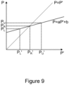
- Figure 9 shows a schematic diagram useful for understanding how backpressure measurements made on the backpressure testing unit 730 may be related to backpressure measurements made on the reference testing unit 400, without the need for testing the manufactured part on the reference testing unit 400 directly.
- a lower limit reference part denoted L a reference part denoted R
- an upper limit reference part denoted U have been tested on the backpressure testing unit 730 (denoted without ⁇ ) and on the reference testing unit 400 (denoted with ⁇ ).
- the solid line plots backpressure values on the backpressure testing unit P against backpressure values on the reference testing unit P').
- the solid line is a straight line parameterised by values a and b.
- a might be equal to 0.8732 and b might be equal to 0.9985.
- the function of the solid line may not need to be known for the purpose of carrying out the methods described herein, for example both a and b may be unknown.
- P may depend on some function of P'.
- the dashed lines indicate how the backpressure on the backpressure testing unit, P L , P R , P U map to backpressure measurement on the reference testing unit P L ', P R ', P U '.
- the dotted line indicates the set of points on the plot for which P is equal to P'.
- the backpressure obtained using the backpressure testing unit P R is equal to the backpressure obtained using the reference testing unit P R '. This may be seen by the intersection of the solid line with the dotted line.
- P U ' is numerically different to P U
- P L ' is numerically different to P L .
- P may depend on an increasing function of P', that is any increase in P corresponds with an increase in P' and any decrease in P corresponds with a decrease in P'.
- P may depend on a non-linear increasing function of P'. Therefore, a backpressure measurement of the manufactured part P M for backpressure testing on the backpressure testing unit 730 between P L and P U may be determined to also fall within P L ' and P U ', without the need to determine the backpressure manufactured part on the reference testing unit P M '. In this way, it may be determined that if P L ⁇ P M ⁇ P U is true, then it follows that P L ′ ⁇ P M ′ ⁇ P U ′ is also true.
- the need to determine P M ' directly may be avoided.
- the need to test each manufactured part 250 on the reference testing unit 400 is avoided, but a reliable determination of whether the backpressure of the manufactured part P M ' would be within the upper and lower limits on the reference testing unit 400 may be obtained nevertheless.
- FIG 10 shows a system 700 for backpressure testing of manufactured parts comprising one or more testing positions 722, 742, 762.
- the system 700 for backpressure testing of manufactured parts 250 comprises the backpressure testing unit 730, for example the backpressure testing unit 730 shown in Figure 5 and/or Figure 7 .
- the backpressure testing unit 730 shown as part of the system 700 in Figure 10 comprises the testing position 722, the backpressure sensor 726 and the flow generator 724.
- the backpressure testing unit 730 may further comprise a controller 710 for carrying out a method 1000 of backpressure testing. The method 1000 will be described in more detail below.
- the backpressure testing unit 730 may further comprise one or more additional testing positions.
- the backpressure testing unit 730 may comprise one or more testing positions 722, 742, 762 configured to accommodate a manufactured part 250 and/or a reference part; one or more flow generators 724, 744, 764 configured to create a flow through each testing position 722, 742, 762; and one or more backpressure sensors 726, 746, 766 configured to measure the backpressure at each testing position 722, 742, 762.
- a respective flow generator 724, 744, 764 is provided such that the 1 st flow generator 724, the 2 nd flow generator 744, up to the n th flow generator 764 may be configured to create a flow through the 1 st testing position 722, the second testing position 742, up to the n th testing position respectively.
- a respective backpressure sensor 726, 746, 766 is provided, such that the 1 st backpressure sensor 726, the 2 nd backpressure sensor 746, up to the n th backpressure sensor 766 may be configured to measure the backpressure at the 1 st testing position 722, the second testing position 742, up to the n th testing position respectively.
- each of the testing position 722, 742, 762 may represent a position where a manufactured part 250 may be tested. In this way, n manufactured parts 250 may be tested in parallel. It is noted that by providing the respective flow generator 726, 746, 766 for each testing position 722, 742, 762, the flow of each testing position 722, 742, 762 may be independently calibrated.
- an automated system 800 for backpressure testing of manufactured parts 250 may be provided.
- robotic arm 850 may be provided to carry out the testing of the manufactured parts 250.
- Figure 11 shows the automated system 800 for backpressure testing of manufactured parts 250.
- the automated system 800 is similar to the system 700, but the automated system 800 further comprises a robotic arm 850 for automatic placing of one or more manufactured parts 250 at the one or more testing positions 722, 742, 762.
- the robotic arm 850 may place the manufactured parts 250 for backpressure testing and/or reference parts at the one or more testing positions 722, 742, 762.
- the backpressure testing unit 730 may be provided as part of a production line comprising a manufacturing station 832. In this way, testing of the manufactured parts 250 output from the manufacturing station 832 may be carried out.
- the manufacturing station 832 may be an apparatus configured to produce the manufactured parts 250. Conveying means, such as a conveyor belt may carry the manufactured parts 250 from the manufacturing station 832 to the backpressure testing unit 730.
- the robotic arm 850 may then pick up one of the manufactured parts 250 and place the manufactured part 250 on one of the one or more testing positions 722, 742, 762 and then use the respective backpressure sensor 726, 746, 766 to measure a backpressure of the manufactured part when the flow is created through the manufactured part 250 by the the respective flow generator 724, 744, 764.
- the robotic arm 850 may pick up the reference part and place the reference part on one of the one or more testing positions 722, 742, 762 and then use the respective backpressure sensor 726, 746, 766 to measure a backpressure of the reference part when the flow is created through the manufactured part 250 by the respective flow generator 724, 744, 764.
- the reference part may be provided to the store accessible by the robotic arm 850 for additional calibrations or verifications. Alternatively, the reference part may be provided to one or more of the other testing positions 722, 742, 762.
- the manufactured part may be provided to one or more additional stations 870, for example a reworking station 876, a visual inspection station 872, and/or a packing station 874.
- the manufactured part may be provided to the one or more additional stations by the conveying means, for example by the robotic arm 850 removing the manufactured part from one of the testing positions 722, 742, 762 and placing the manufactured part on the conveying means, such as a conveyor belt.
- a test result may be determined based on the backpressure measurement. How the test results may be determined will be explained in more detail below with reference to the method steps. For example, if the test result is a negative test result, the manufactured part may be directed to the reworking station 876. Alternatively, if the test result is a positive test result, the manufactured part may be directed to the visual inspection station 872 and/or the packing station 874.
- each of the manufactured parts 250 comprises a unique identifier, such as a barcode.
- the unique identifier of the manufactured part 250 may be identified (for example by scanning the barcode) as the manufactured part is positioned or removed from one of the one or more testing positions 722, 742, 762. In this way, the backpressure measurement made by the respective backpressure sensor 726, 746, 766 may be associated with the unique identifier. The unique identifier accordingly may allow the test result to be associated with each of the manufactured parts 250.
- the backpressure testing unit may further comprise a controller 710 configured to carry out a method 1000 of backpressure testing.
- the controller may comprise a memory for storing instructions and/or data, a processor, and/or signal outputs/inputs for transmitting instructions to/receiving instructions from the other components of the system for backpressure testing 700, 800.
- the controller 710 may be configured to transmit instructions to the robotic arm 850.
- a method 1000 of backpressure testing manufactured parts 250 is provided.
- the method may comprise comparing a backpressure measurement of a manufactured part 250 on the backpressure testing unit 730 to a backpressure measurement of the reference part on the backpressure testing unit 730, and checking that the backpressure measurement of the manufactured part 250 falls within an upper limit and a lower limit defined with respect to the backpressure measurement of the reference part.
- the backpressure of the manufactured part 250 may be checked against the reference part.
- the reference part may itself have been checked on a reference testing unit 400.
- by testing the backpressure of the manufactured part 250 in this way it may be possible to reduce an amount of time to taken to test each manufactured part 250 and/or test one or more manufactured parts 250 in parallel. Additionally, it may be possible to avoid a need to test the manufactured part 250 on the reference testing unit 400.
- the reference part may be an orifice plate 100 configured to have a backpressure which matches a reference backpressure when or if tested on the reference testing unit 400.
- the reference backpressure may comprise a backpressure which would be suitable for the manufactured part 250 to have when used, for example when used as part of an exhaust system.
- Figure 12 shows an overview of the method 1000 of backpressure testing manufactured parts. As shown in Figure 12 , the method 1000 comprises:
- the limits set in step c) may themselves be based on measurements derived from a measurement in step b) of the reference part.
- the limits set in step c) may be based on a backpressure measurement of an upper limit reference part and/or a lower limit reference part.
- the method 1000 of backpressure testing manufactured parts comprises:
- an advantage of the method 1000 may be that it is possible to test one or more manufactured parts on the backpressure testing unit 730, without needing to test the one or more manufactured parts 250 on the reference testing unit 400. Nevertheless, by providing one or more reference parts, it is possible to understand how the one or more manufactured parts 250 might behave on the reference testing unit 400 without testing the one or more manufactured parts 250 on the reference testing unit 400 directly. As outlined above in the statement about step a), it may be important to determine the backpressure of the reference part when or if tested on the reference testing unit (P R '). As will be explained further below, the backpressure of the reference part when or if tested on the reference testing unit (P R ') may be determined by experimentation (e.g.
- step a) i) measuring on the reference testing unit 400, as in step a) i)), and/or theoretical calculation (e.g. as in step a) ii) where steps a) i) and a) ii) are shown in Figure 13 and set out in detail below). How the backpressure of the reference part when or if tested on the reference testing unit (P R ') may be determined will now be explained in more detail with reference to Figure 13 .
- Figure 13 shows an embodiment of the step a) of obtaining one or more reference parts and determining the reference backpressure measurement for each reference part indicative of the backpressure of that reference part when or if tested on the reference testing unit (P R ').
- determining the reference backpressure measurement for each reference part indicative of the backpressure of that reference part when or if tested on the reference testing unit (P R ') in step a) comprises:
- obtaining the reference part may comprise obtaining an orifice plate configured to provide the reference backpressure measurement when or if tested on the backpressure testing unit (P R ').
- obtaining the reference part may comprise obtaining a reference part of the same type as the manufactured part 250 (for example if the manufactured part comprises a filter, the reference part may also comprise a filter) configured to provide the reference backpressure measurement when or if tested on the backpressure testing unit (P R ').
- the reference backpressure measurement when or if tested on the backpressure testing unit (P R ') may correspond with a target pressure or a tolerated pressure for the manufactured part 250 when or if installed in an end use system, such as an exhaust system.
- a target mass flow rate Q m Target may be used as the mass flow rate.
- the target mass flow rate Q m Target may be equivalent to an industry standard test volumetric flow rate such as 600m 3 /hr.
- the backpressure of the reference part when or if tested on the reference testing unit P R ' may be determined by experimentation.
- the backpressure of the reference part when or if tested on the reference testing unit 400 may be determined by measuring the backpressure of the reference part on the backpressure testing unit 400.
- the backpressure of the reference part may be tested on the backpressure testing unit 400 by positioning the reference part on the one of the testing positions 722, 742, 762. From there, a flow may be generated using the respective flow generator 724, 744, 764.
- the mass flow rate by using the variable orifice plate 450 and the variable orifice plate backpressure sensor 420.
- a variable orifice plate 450 to adjust the mass flow rate, it is possible to ensure the backpressure of the reference part when measured on the reference testing unit 400 is measured at the target value mass flow rate Q m Target .
- the target mass flow rate Q m Target may be a typical mass flow rate Q m Target of an exhaust system or an industry standard test mass flow rate, for example a mass flow rate equivalent to a volumetric flow rate of 600m 3 /hr. In this way, a measurement of the reference part on the reference testing unit 400 may be made.
- the backpressure of the reference part when or if tested on the reference testing unit P R ' may be determined by theoretical calculation, particularly in embodiments where the reference part has a mathematically derivable effect on pressure of a flow.
- the reference part may comprise an orifice plate 100. As has been explained previously, it is possible provide an orifice plate 100 with a particular backpressure by varying the relative diameter ⁇ (or another geometrical parameter) of the orifice plate 100.
- the reference part may be an orifice plate 100 produced according to a particular set of standards, for example the set of standards defined by "ISO 5167-2 Measurement of fluid flow by means of pressure differential devices inserted in circular cross-section conduits running full - part 2: orifice plates”.
- the backpressure of the reference part when or if tested on the reference testing unit P R ' may be determined by following step a) i), step a) ii), and/or step a) i) and step a) ii). In this way, an experimental determination, a theoretical determination, and/or an experimental and a theoretical determination of the backpressure of the reference part when or if tested on the reference testing unit P R ' may be made.
- the method 1000 of backpressure testing manufactured parts further comprises: b) calibrating one or more testing positions 722, 742, 762 of a backpressure testing unit 730 using the one or more reference parts;
- Figure 14 shows an embodiment of the step b) of calibrating one or more testing positions 722 of a backpressure unit 730 using one or more reference parts. Calibrating the one or more testing positions of the backpressure testing unit 730 in step b) comprises:
- the flow generator 724, 744, 764 of the backpressure testing unit 730 comprises a fan.
- the mass flow rate Q m may be increased.
- the speed of the flow may be decreased.
- the calibrated flow may correspond with a particular rotation speed ⁇ and/or rotation frequency of the flow generator 724. In this way, the reference part is used to obtain a calibrated flow.
- the reference part may be installed at one of the one or more testing positions 722, 742, 762.
- the robotic arm 850 may be used to install the reference part at the one or more testing positions 722, 742, 762.
- the robotic arm may install the reference part at the one or more testing positions 722, 742, 762 sequentially.
- the robotic arm 850 may install the reference part at the one or more testing positions 722, 742, 762 contemporaneously.
- one reference part for each testing position 722, 742, 762 which is contemporaneously calibrated may be provided.
- the flow may be created through the one or more testing positions 722, 742, 762.
- the rotation speed ⁇ of the respective flow generator 724, 744, 764 may be increased to create the flow through the one or more testing positions 722, 742, 762.
- Increasing the rotation speed ⁇ may increase the mass flow rate and decreasing the rotation speed ⁇ may decrease the mass flow rate.
- the backpressure measured by the respective backpressure sensor 726, 746, 766 may increase or decrease.
- the backpressure of the reference part when tested on the backpressure testing unit P R depends on the mass flow rate, which in turn depends on the rotation speed ⁇ .
- the backpressure of the reference part when tested on the backpressure testing unit P R may also depend on the backpressure of the reference part when or if tested on the reference testing unit P R '.
- a calibrated flow may be determined.
- the reference testing unit 730 may, compared with the backpressure testing unit 730, further comprise the calibrated orifice plate 450 and as such it is possible to determine the mass flow rate Q m using the reference testing unit 400.
- the backpressure testing unit 730 may lack the ability to determine the mass flow rate Q m .
- the rotation speed ( ⁇ ) may be used to increase or decrease the mass flow rate Q m , it may be unknown how the mass flow rate Q m is being increased or decreased in the backpressure testing unit 730.
- the calibrated rotation speed ⁇ Cal may comprise a rotation speed such that the backpressure of the reference part when or if tested on the backpressure testing unit P R is equal to the backpressure of the reference part when or if tested on the reference testing unit P R '.
- P R P R ′
- the speed of the fan from the respective flow generator 724, 744, 764 may be adjusted to the calibrated rotation speed ⁇ Cal , where it may be determined that the calibrated rotation speed ⁇ Cal has been reached because the backpressure determined by the respective backpressure sensor 726, 746, 766 has a value equivalent to P R '.
- the calibrated flow may be used thereafter in step d) for each of the one or more testing positions 722, 742, 762.
- the calibrated fan speed ⁇ Cal may be provided to the controller 710 and/or stored in the memory of the controller 710.
- the controller 710 may be further configured to adjust the rotation speed ⁇ by sending an electronic signal to a fan motor. In this way, the controller 710 may be used to adjust the rotation speed ⁇ of the respective flow generator 724, 744, 764 to the calibrated rotation speed ⁇ Cal .
- the fan speed of the respective flow generator 724, 744, 764 may be monitored by the controller 710 and/or not maintained at the calibrated rotation speed ⁇ Cal .
- the backpressure testing unit 730 may comprise one or more testing positions 722, 742, 762 and respective backpressure sensors 726, 746, 766 and respective flow generators 724, 744, 764.
- the controller 710 may be configured to carry out step b) for each testing position 722, 742, 762 individually and/or contemporaneously.
- the calibrated flow ⁇ Cal for each testing positions 722, 742, 762 may be equivalent. However, due to variability in the backpressure testing unit 730 and/or in order to increase the accuracy of the results, it is preferable to determine the calibrated flow ⁇ Cal individually for each of the one or more position testing positions 722, 742, 762.
- the method 1000 of backpressure testing manufactured parts 250 further comprises: c) setting an upper backpressure limit and a lower backpressure limit for each of the one or more testing positions.
- the step c) comprises setting the upper backpressure limit and the lower backpressure limit as a multiple x of the reference backpressure measurement P R and/or a pressure offset from the reference backpressure measurement P R .
- the upper backpressure limit may be P R +xP R and the lower backpressure limit may be P R -xP R
- the step c) comprises using one or more upper limit reference parts and one or more lower limit reference parts.
- Figure 15 shows an embodiment of the step c) of setting an upper backpressure limit and a lower backpressure limit for each of the one or more testing positions using one or more upper limit reference parts and one or more lower limit reference parts.
- the step c) of setting the upper backpressure limit and the lower backpressure limit for each of the one or more testing positions comprises:
- the upper backpressure limit may be the backpressure of the upper limit reference part when tested on the backpressure testing unit P U .
- the lower backpressure limit may be the backpressure of the lower limit reference part when tested on the backpressure testing unit P L .
- the one or more upper limit reference parts may comprises one or more similar parts configured to provide an upper limit reference at the one or more testing positions 722, 742, 762. In this way, the one or more upper limit reference parts may be used to calibrate the upper limit at the one or more testing positions 722, 742, 762 contemporaneously.
- the one or more lower limit reference parts may comprise one or more similar parts configured to provide a lower limit reference at the one or more testing positions 722, 742, 762. In this way, the one or more lower limit reference parts may be used to calibrate the lower limit at the one or more testing positions 722, 742, 762 contemporaneously.
- one of the upper limit reference parts and one of the lower limit reference parts may be used to calibrate the one or more testing positions 722, 742, 762 may be calibrated sequentially.
- one or more upper limit reference parts and one or more lower limit reference parts may be obtained.
- the one or more upper limit reference parts and the one or more lower limit reference parts may comprise orifice plates.
- the upper limit reference part may comprise an orifice plate with an increased backpressure compared with the reference part.
- the lower limit reference part may comprise an orifice plate with a decreased backpressure compared with the reference part.
- the lower limit reference part may have a lower relative diameter compared with the upper limit reference part.
- the backpressure of an orifice plate may be increased with a smaller relative diameter.
- the lower limit reference part may comprise an orifice plate with a larger relative diameter compared with the relative diameter of an upper limit reference part, the upper limit reference part comprising an orifice plate.
- the reference part may comprise an orifice plate.
- the relative diameter of the lower limit reference part ⁇ L , the relative diameter of the upper limit reference part ⁇ U , and the relative diameter of the reference part ⁇ R may be related by the following inequality: ⁇ L > ⁇ R > ⁇ U
- the backpressure of the lower limit reference part when tested on the reference testing unit P L ' may be lower compared with the backpressure of the reference part when or if tested on the reference testing unit P R '.
- the backpressure of the upper limit reference part when tested on the reference testing unit P U ' may be higher compared with the backpressure of the reference part when or if tested on the reference testing unit P R '.
- the backpressure of the reference part when tested on the backpressure testing unit P R may be equal to the backpressure of the reference part when or if tested on the reference testing unit P R '.
- the backpressure of the lower limit reference part when tested on the backpressure testing unit P L may be numerically different to the backpressure of the lower limit reference part when tested on the reference testing unit P L '.
- the backpressure of the upper limit reference part when tested on the backpressure testing unit P U may be numerically different to the backpressure of the upper limit reference part when tested on the reference testing unit Pu'.
- the appropriate diameters for the upper limit reference part and the lower limit reference part may be determined theoretically, for example by using the standards set by ISO 5167-2 and/or by using fluid dynamic computational modelling. Alternatively, or additionally, the diameter of the upper limit reference part and the lower limit reference part may be determined experimentally using the reference testing unit 400. For example, a range of diameters may be trialled until a part with an appropriate backpressure is obtained.
- the upper limit reference part may be installed on one of the one or more testing positions of the backpressure testing unit 730.
- the robotic arm 860 may be used to install the upper limit reference part on one of the one or more testing positions 722, 724, 726.
- the respective flow generator 724, 744, 764 may then be used to provide the calibrated flow through the respective testing position 722, 742, 762 by setting the respective flow generator 724, 744, 764 to the calibrated rotation speed ⁇ Cal .
- a backpressure measurement may then be made by the respective backpressure sensor 726, 746, 766 of the upper limit reference part in one of the one or more testing positions 722, 742, 762.
- the measurements made by the backpressure testing unit 730 may correspond with but be numerically different to the measurements made by the reference testing unit 400.
- the upper limit reference part may be installed on one of the one or more testing positions of the backpressure testing unit 730.
- the robotic arm 860 may be used to install the upper limit reference part on one of the one or more testing positions 722, 742. 762.
- the respective flow generator 724, 744, 764 may then be used to provide the calibrated flow through the respective testing position 722, 742. 762 by setting the respective flow generator 724, 744, 764 to the calibrated rotation speed ⁇ Cal .
- a backpressure measurement may then be made by the respective backpressure sensor 726, 746, 766 of the upper limit reference part in one of the one or more testing positions 722, 742, 762.
- the measurements made by the backpressure testing unit 730 may correspond with but be numerically different to the measurements made by the reference testing unit 400.
- the method 1000 of backpressure testing manufactured parts further comprises: d) thereafter using the one or more testing positions 722, 742, 762 to assess the backpressure of one or more manufactured parts 250;
- Figure 16 shows an embodiment of the step d) of using the one or more testing positions to assess the backpressure of one or more manufactured parts.
- using the one or more testing positions to assess the backpressure of one or more manufactured parts 250 in step d) comprises:
- the or each manufactured part referred to in steps d) i) to d) iv) may comprise the or each manufactured part for backpressure testing.
- the or each manufactured part referred to in steps d) i) to d) iv) may comprise manufactured parts for backpressure testing obtained from the manufacturing station 832.
- the or each manufactured part 250 may be installed on one of the one or more testing positions 722, 742, 762 of the backpressure testing unit 730.
- the robotic arm 860 may be used to install the or each manufactured part 250 on one of the one or more testing positions 722, 742, 762.
- step d) ii) the flow generator 724, 744, 764 may be used to flow air through the testing position 722, 724, 726. As has already been explained, the flow generator 724, 744, 764 is operated at the calibrated rotation speed ⁇ Cal determined in step (b).
- step d) iii)..the backpressure measurement of the or each manufactured part P M may be measured by the respective backpressure sensor 726, 746, 766.
- the backpressure measurement may be provided to the controller 710.
- step d) iv) whether or not the backpressure measurement is within an acceptable range is determined.
- the controller 730 may evaluate whether the inequality: P L ⁇ P M ⁇ P U is true.
- the controller 730 may evaluate whether the inequality: P R ⁇ xP R ⁇ P M ⁇ P R + xP R is true.
- upper back pressure limit and the lower back pressure limit include an offset to account for the precision of the test.
- the P M may be within an acceptable range, and the manufactured part 250 may be assigned a positive result. In particular, it may be determined from the above that the backpressure of the manufactured part if tested on the reference testing unit P M ' would also be within an acceptable range. In some embodiments, the unique identifier of the manufactured part may be scanned to associate the manufactured part with the positive result. If the inequality (14) and/or (15) is false, then the P M may not be within an acceptable range, and the manufactured part 250 may be assigned a negative result. In particular, it may be determined from the above that the backpressure of the manufactured part if tested on the reference testing unit P M ' would also be not be within an acceptable range. In some embodiments, the unique identifier of the manufactured part 250 may be scanned to associate the manufactured part 250 with the negative result.
- the method 1000 further comprises: e) periodically verifying the backpressure measurements at the one or more testing positions 722, 742, 762 by assessing the backpressure of one or more verification reference parts at each of the one or more testing positions 722, 742, 762.
- Figure 17 shows an embodiment of the step e) of periodically validating the backpressure measurements at the one or more testing positions by assessing the backpressure of one or more verification reference parts at each of the one or more testing positions.
- the step e) may comprise a step e) 0) of obtaining one or more verification reference parts having a backpressure measurement when tested on one of the backpressure testing unit Pv that is between the upper backpressure limit and the lower backpressure limit.
- the calibration of the respective backpressure sensor 726, 746, 766 the calibrated rotation speed provided by the respective flow generator 724, 744, 764, dirt or dust introduced into the system, temperature fluctuations, may cause the backpressure measurements determined by the backpressure sensor 726 to increase and/or decrease relative to previous measurements by the same backpressure sensor 726. As such, it is possible that manufactured parts 250 may be incorrectly assigned a negative result and/or incorrectly assigned a positive result.
- the method 1000 may further comprise the step e) of periodically validating the method 1000.
- the step e) 0) may comprise determining a backpressure measurement of a verification reference part on the backpressure testing unit P V .
- P V may be between P L and P U .
- Step e) 0) may comprise obtaining one or more verification reference parts having a backpressure measurement when tested on backpressure testing unit Pv that is between the upper backpressure limit and the lower backpressure limit.
- the verification reference part may be equivalent to the reference part, for example P V may be equal to P R .
- the verification reference part may comprise an orifice plate 100.
- the verification reference part may comprise a filter 300.
- the verification reference part may be tested similarly to how the manufactured parts 250 are tested.
- the verification reference part may be tested by periodically:
- step e) ii) the flow generator 724, 744, 764 may be used to create a flow through the testing position 722, 724, 726.
- the flow generator 722, 742, 762 may be operated at the calibrated rotation speed ⁇ Cal determined in step (b).
- step e) iii) the backpressure measurement of the verification part on the backpressure testing unit P V may be measured by the respective backpressure sensor 726, 746, 766.
- the backpressure measurement of the verification part on the backpressure testing unit Pv may be provided to the controller.
- step e) iv) whether or not the backpressure measurement of the verification part on the backpressure testing unit P V is within an acceptable range may be determined.
- the controller 730 may evaluate whether the inequality: P L ⁇ P V ⁇ P U is true.
- the controller 730 may evaluate whether the inequality: P R ⁇ xP R ⁇ P V ⁇ P R + xP R is true.
- the upper back pressure limit and the lower back pressure limit include an offset to account for the precision of the test.
- the P V may be within an acceptable range. This in turn may indicate that backpressure measurements by the backpressure sensor 726 have not increased and/or decreased relative to previous measurements by the same backpressure sensor 726. As such, based on the inequality (16) and/or (17) being true, measurements of manufactured parts in step d) may be validated.
- a number of previously tested manufactured parts and/or a number of subsequently tested manufactured parts are validated.
- manufactured parts tested within a time window of the determination that the inequality is true may be validated. If the inequality is false, then the P V may not be within an acceptable range. This in turn may indicate that backpressure measurements by the backpressure sensor 726, 746, 766 have increased and/or decreased relative to previous measurements by the same backpressure sensor 726. As such, based on the inequality being false, measurements of manufactured parts in step d) may be invalidated.
- a number of previously tested manufactured parts 250 and/or a number of subsequently tested manufactured parts 250 are invalidated.
- manufactured parts 250 tested within a time window of the determination that the inequality is false may be invalidated.
- validating a manufactured part 250 may comprise using the controller 710 to associate a validation signal with the unique identifier of the manufactured part.
- invalidating a manufactured part may comprise using the controller to associate an invalidation signal with the unique identifier of the manufactured part.
- the controller 710 may be configured to carry out the above steps periodically by carrying out steps e) i) to e) iv) every 1s, every 100s, every 1000s, every 10,000s of operation of method 1000.
- the controller 710 may be configured to carry out the above steps periodically by carrying out steps 1920 to 1980 before and/or after each measurement of the manufactured part for backpressure testing, before and/or after measurement of 10 manufactured parts for backpressure testing, before and/or after measurement of 100 manufactured parts for backpressure testing, before and/or after measurement of 1000 manufactured parts for backpressure testing.
- the manufactured part 250 may comprise a filter 300.
- the manufactured part 250 may comprise a filter 300 such as a catalytic filter for use in an exhaust system.
- the filter 300 may comprise pores through which a flow may pass, such that one or more components of the flow may be blocked and/or catalysed by the filter 300.
- the filter 300 may comprise a planar sheet of material comprising the pores.
- the filter 300 may comprise one or more plugs 922, 924, 926, 942, 944, 946, and one or more channels, 943, 945, 947, 923, 925, 927.
- the flow may travel through the walls 903, 905, 907, the walls comprising the pores.
- FIG 18 shows a photograph of a top view of the catalytic filter 900, generally structured similarly to the filter 300 shown schematically as a side view in Figure 4 .
- the dotted line in Figure 18 and Figure 4 may indicate the same direction.
- the catalytic filter 900 comprises channels 942, 944, 946 and plugs 922, 924, and 926.
- the flow may travel through the channels 942, 944, 946, through the walls and out through a set of channels located beneath the plugs 922, 924, 926, the channels beneath the plugs 922, 924, 926 not being visible in the Figure.
- the chequerboard structure of the filter 900 ensures the flow must pass through the pores in the walls to pass through the filter 900.
Landscapes
- Engineering & Computer Science (AREA)
- Chemical & Material Sciences (AREA)
- Chemical Kinetics & Catalysis (AREA)
- General Engineering & Computer Science (AREA)
- Mechanical Engineering (AREA)
- Combustion & Propulsion (AREA)
- Health & Medical Sciences (AREA)
- Toxicology (AREA)
- Analytical Chemistry (AREA)
- Pathology (AREA)
- Immunology (AREA)
- General Physics & Mathematics (AREA)
- General Health & Medical Sciences (AREA)
- Biochemistry (AREA)
- Physics & Mathematics (AREA)
- Life Sciences & Earth Sciences (AREA)
- Measuring Volume Flow (AREA)
- Measuring Fluid Pressure (AREA)
Abstract
Description
- The disclosure relates to the field of backpressure testing of manufactured parts, for example flow through monoliths and filters.
- Exhaust fumes are a waste product produced from combustion of a fuel, for example the combustion of petrol in an internal combustion engine. Exhaust fumes may comprise a mixture of components such as air, carbon dioxide, carbon monoxide, nitrous oxide, sulfur dioxide, hydrocarbons, benzene and/or particulates. The components of the exhaust fumes may vary depending on the fuel being combusted. Exhaust fumes can be harmful to a user and/or damaging to the environment.
- An exhaust system may be used to pipe exhaust fumes away from one location to another. For example, a vehicle exhaust system may pipe exhaust fumes from an internal combustion engine to the outside of a vehicle. This may avoid inhalation of the exhaust fumes by the user.
- In many cases, it is desirable to remove a component from the exhaust fumes. For this reason, flow through monoliths and filters may be used within the exhaust system to remove components from the exhaust fumes. The removal of components from the exhaust fumes may involve forcing the exhaust fumes through small holes of a filter, which may physically block some components (e.g. particulate components) and/or chemically convert some components using the flow through monolith or filter by catalysing reactions of components (e.g. reduction of nitrous oxides, oxidation of carbon monoxide, oxidation of hydrocarbons and/or the like). By removing some components and/or altering the chemical composition of some components, the exhaust fume may be made less harmful and/or less environmentally damaging.
- When a flow of exhaust fumes are passed through a porous substrate, especially a filter, a change in pressure may result. The pressure change may be referred to as a backpressure. A backpressure which is excessively high for a particular mass flow rate may impair the functionality of the exhaust system and/or damage the exhaust system. As such, a filter manufacturer will often seek to certify that a backpressure of a manufactured part, for example a filter falls within a particular range for a mass flow rate representative of the mass flow rate in the exhaust system.
- A manufacturer may test the backpressure of a filter and/or other manufactured part using a backpressure testing apparatus such as a SuperFlow flowbench. However, SuperFlow flowbenches (e.g. the SF1020 model available from SuperFlow Dynamometers & Flowbenches), are designed for infrequent measurement of modified car parts such as cylinder heads and ports. Factors such as the cost, the long cycle time (approximately 20-25s), and the size of the SuperFlow flowbench may hinder its suitability for in-line testing of filters and/or other manufactured parts. For these reasons, a manufacturer would not generally test 100% of the final product for conformity with backpressure standards, leaving open the possibility that defective filters and/or other manufactured parts may pass unnoticed.
- Against this background, it is desirable to provide improved methods of backpressure testing of filters and/or other manufactured parts.
- In some aspects of this disclosure, there is provided a method of backpressure testing manufactured parts, the method comprising:
- a) obtaining one or more reference parts and determining a reference backpressure measurement for each reference part indicative of the backpressure of that reference part when or if tested on a reference testing unit;
- b) calibrating one or more testing positions of a backpressure testing unit using the one or more reference parts;
- c) setting an upper backpressure limit and a lower backpressure limit for each of the one or more testing positions; and
- d) thereafter using the one or more testing positions to assess the backpressure of one or more manufactured parts;
- wherein, calibrating the one or more testing positions of the backpressure testing unit in step b) comprises:
- b) i) installing one of the reference parts in a or each testing position of the backpressure testing unit;
- b) ii) creating a flow through the or each testing position;
- b) iii) establishing a calibrated flow for the or each testing position by adjusting the flow through the or each testing position until a backpressure measurement of the reference part in the or each testing position corresponds to the reference backpressure measurement of the respective reference part;
- b) iv) thereafter using the calibrated flow for the or each testing position during step d);
- wherein, using the one or more testing positions to assess the backpressure of one or more manufactured parts in step d) comprises:
- d) i) installing a manufactured part in a or each testing position of the backpressure testing unit;
- d) ii) flowing the calibrated flow determined from step b) iii) through the or each testing position;
- d) iii) measuring a backpressure measurement of the or each manufactured part;
- d) iv) comparing the backpressure measurement of the or each manufactured part against the upper backpressure limit and the lower backpressure limit for the respective testing position and generating and outputting a test result indicative of whether the backpressure measurement is within an acceptable range compared to the upper backpressure limit and the lower backpressure limit.
- wherein, calibrating the one or more testing positions of the backpressure testing unit in step b) comprises:
- In this way, it is possible to test the backpressure of manufactured parts with improved efficiency. For example, it may be possible to test the manufactured parts in a lower amount of time and/or to test the manufactured parts in parallel. In this way, it may be made possible to test 100% of a large set of manufactured parts without the testing taking an excessive amount of time.
- According to another aspect of this disclosure, there is provided a controller configured to carry out the method.
- In this way, the controller may be used to control the testing of the backpressure of manufactured parts with improved efficiency. For example, it may be possible to test the manufactured parts in a lower amount of time and/or to test the manufactured parts in parallel. In this way, it may be made possible to test 100% of a large set of manufactured parts without the testing taking an excessive amount of time.
- According to another aspect of this disclosure, there is provided:
- a system for backpressure testing of manufactured parts, comprising
the controller configured to carry out the method; and
a backpressure testing unit comprising:- one or more testing positions configured to accommodate a manufactured part and/or a reference part;
- a flow generator configured to create a flow through each testing position; and
- a backpressure sensor configured to measure backpressure at each testing position.
- In this way, the controller may be used to control the testing the backpressure of the manufactured parts on the backpressure testing unit with improved efficiency. For example, it may be possible to test the manufactured parts on the backpressure testing unit in a lower amount of time and/or to test the manufactured parts in parallel, when compared with backpressure testing carried out on alternative testing units, such as a reference testing unit. In this way, it may be made possible to test 100% of a large set of manufactured parts without the testing taking an excessive amount of time, as it may otherwise take if the reference testing unit were used for testing the backpressure of the manufactured parts.
- A specific embodiment of the disclosure will now be described, by way of example only, with reference to the accompanying drawings in which:
-
Figure 1 shows a front view of an orifice plate. -
Figure 2 shows a side view of a system for measuring backpressure of an orifice plate -
Figure 3 shows a side view of a system for measuring backpressure of a manufactured part. -
Figure 4 shows a flow through a portion of a filter. -
Figure 5 shows a backpressure testing unit. -
Figure 6 shows a reference testing unit. -
Figure 7 shows a backpressure testing unit. -
Figure 8 shows a plot of backpressure measurements made using the backpressure testing unit plotted against backpressure measurements made using the reference testing unit. -
Figure 9 shows a schematic diagram useful for understanding how backpressure measurements made on the backpressure testing unit may be related to backpressure measurements made on the reference testing unit. -
Figure 10 shows a system for backpressure testing of manufactured parts. -
Figure 11 shows an automated system for backpressure testing of manufactured parts. -
Figure 12 shows a method of backpressure testing manufactured parts. -
Figure 13 shows a method of obtaining one or more reference parts and determining a reference backpressure measurement for each reference part indicative of the backpressure of that reference part when or if tested on a reference testing unit. -
Figure 14 shows a method of calibrating one or more testing positions of a backpressure unit using one or more reference parts. -
Figure 15 shows a method of setting an upper backpressure limit and a lower backpressure limit for each of the one or more testing positions. -
Figure 16 shows a method of using the one or more testing positions to assess the backpressure of one or more manufactured parts. -
Figure 17 shows a method of obtaining one or more verification reference parts having a backpressure measurement when tested on one of the one or more testing positions that is between the upper limit and the lower limit. -
Figure 18 shows a photograph of part of a filter. - In some aspects of this disclosure, a
method 1000 of backpressure testing manufacturedparts 250 is provided.Figure 12 shows an embodiment of themethod 1000. - In this description, flows comprising a movement of a flow material are described. The flow material may comprise air, particles, gas, exhaust fumes and/or the like. In the flows, the flow material may travel from one location to another, for example through pipes. The direction of travel of flows is illustrated in the figures by arrows, where the head of the arrow indicates a downstream location of the flow and the tail of the arrow indicates an upstream location of the flow.
- For the purposes of carrying out the
method 1000 of backpressure testing, thebackpressure testing unit 730 may be provided, as shown inFigure 5 . Thebackpressure testing unit 730 may comprise atesting position 722 configured to accommodate amanufactured part 250, aflow generator 724 configured to create a flow through thetesting position 722, abackpressure sensor 726 configured to measure backpressure at thetesting position 722, and acontroller 710 configured to carry out themethod 1000. As the air is caused to flow through the manufactured part, a resistance to the flow is created by the manufactured part and/or a reference part. This in turn creates a pressure differential across the manufactured part and/or the reference part which is measurable by the backpressure sensor. - The manufactured part may be any part through which the flow material may pass. The manufactured part may be a filter, an orifice plate, a pipe, and/or the like. In some embodiments, the manufactured part may comprise a manufactured part used in an exhaust system. The reference part may be configured to provide a reference backpressure measurement when or if tested on a
reference testing unit 400, such as thereference testing unit 400 shown inFigure 6 . In some embodiments, one or more manufactured parts may be provided from amanufacturing station 832 such as a production line of the manufactured parts. The manufactured parts for backpressure testing may have untested backpressures and as such themethod 1000 may be used to determine whether or not the backpressure of the manufactured parts are within an acceptable range of backpressures. The reference part may be a filter, an orifice plate, a pipe, and/or the like. In some embodiments, the manufactured part and the reference part may be the same type of part. For example, the manufactured part for backpressure testing may be a filter and the reference part may also be a filter. In some embodiments, the manufactured parts for testing and the reference part may be different types of part. For example, the manufactured parts for testing may be a filter and the reference part may be an orifice plate. - How a backpressure measurement of a manufactured part and/or a reference part can be made will now be explained in more detail below.
-
Figure 1 shows anorifice plate 100. Theorifice plate 100 may comprise a sheet ofmaterial 102 and abore 104 of diameter d through the sheet ofmaterial 102. In some embodiments, the sheet ofmaterial 102 may comprise ahandle 106 which may be used to position theorifice plate 100 in a flow. In some embodiments, the sheet ofmaterial 102 may have a diameter D. When positioned in a flow, air may be forced to pass through thebore 104 to travel from an upstream side of theorifice plate 100 to a downstream side of theorifice plate 100. -
Figure 2 shows a side view of asystem 200 for measuring backpressure of theorifice plate 100. Shown inFigure 2 , a flow may travel within thewalls 202 of a pipe from an upstream location to a downstream location. How the flow is generated is not shown inFigure 2 , but will be explained in more detail later in this description. The flows are indicated by arrows, travelling from an upstream location at the tail of the arrow to a downstream location at the head of the arrow. Also shown inFigure 2 , the flow may pass through theorifice plate 100, positioned in the path of the flow. In this way, the flows may be forced to pass through thebore 104 of theorifice plate 100. As can be seen, this causes a constriction of the flow as the flow passes through thebore 104. This constriction in the flow produces a change in a pressure of the flow. Thus, at a first location upstream of theorifice plate 100, the pressure may be different compared with a second location downstream of theorifice plate 100. Thus, the pressure at the first location upstream of the orifice plate p1 may differ compared with the pressure at the second location downstream of the orifice plate p2. In some embodiments, there may be a pressure loss between the pressure at a first location upstream of the orifice plate p1 and the pressure at a second location downstream of the orifice plate p2. The pressure change p1-p2 may be defined as the backpressure P of theorifice plate 100. It is noted that in this disclosure backpressures are denoted by an upper case P. Other pressure measurements, such as those taken at the first and second location as noted above, are denoted using a lower case p. Thus, the backpressure P may be provided by the equation:
- The backpressure of the
orifice plate 100 may be determined by abackpressure sensor 220 comprising adownstream pressure sensor 224 configured to measure the pressure at the second location downstream of the orifice plate p2. In some embodiments, the pressure at the first location upstream of the plate p1 may be determined and/or assumed to be atmospheric pressure. Thebackpressure sensor 220 may output the difference between the atmospheric pressure and the pressure detected by thedownstream pressure sensor 224. In some embodiments,backpressure sensor 220 may comprise anupstream pressure sensor 222 configured to measure the pressure at the first location upstream of the orifice plate p1 and adownstream pressure sensor 224 configured to measure the pressure at the second location downstream of the orifice plate p2. Thebackpressure sensor 220 may output the difference between the pressure detected by theupstream pressure sensor 222 and thedownstream pressure sensor 224. - The geometric properties of the
orifice plate 100 may influence the backpressure of theorifice plate 100. For example, the backpressure of theorifice plate 100 may change as the diameter of thebore 104 is changed relative to the overall size of theorifice plate 100. The geometric properties of theorifice plate 100 may include the flatness of the orifice plate, the diameter of the bore, the diameter of the orifice plate, the relative diameter (the ratio of the diameter of the bore and the diameter of the orifice plate), the shape of the bore, the thickness of the orifice plate and/or other parameters. For theorifice plate 100 shown inFigure 1 , the diameter of the bore is labelled d. The diameter of the pipe is labelled D. The relative diameter β may be provided by:
- The relative diameter β may vary between 0 and 1. A relative diameter β of 1 may correspond with an
open pipe 202 and a relative diameter β of 0 may correspond with a blockedpipe 202. Thus, as the relative diameter β decreases, the backpressure increases. - In some embodiments, the
orifice plate 100 may be produced according to a particular set of standards, for example the set of standards defined by "ISO 5167-2 Measurement of fluid flow by means of pressure differential devices inserted in circular cross-section conduits running full - part 2: orifice plates". By manufacturing orifice plates according to a set of standards, it is possible predict how a change in a geometric parameter will affect the backpressure of an orifice plate. In some embodiments, a machining accuracy of a cutting tool for preparing thebore 104 may affect how precisely the orifice plate may be prepared which in turn may affect the backpressure of theorifice plate 100. As such, as high a machining accuracy as possible may be desirable for preparing theorifice plate 100. In some embodiments, machining accuracy of below 100µm may be used. In some embodiments, machining accuracy of below 10µm may be used. In some embodiments, machining accuracy of below 1µm may be used. - In some embodiments, the shape of
bore 104 may be a shape other than circular, for example an ellipse and/or other non-circular shape. In some embodiments, the bore may be a section of a circular shape, for example an annulus. In some embodiments, the diameter of the bore on the upstream side of theorifice plate 100 may be different to the diameter of the bore on the downstream side of theorifice plate 100, for example thebore 104 may define a section of a cone. In some embodiments, there may be one or more bores 104. - The
system 200 shown inFigure 2 may be used to measure the backpressure of other manufactured parts, for example filters, placed in the path of the flow.Figure 3 shows a side view of a manufactured part, positioned in a flow. InFigure 3 , instead of theorifice plate 100, amanufactured part 250 is placed in the path of the flow. In much the same way as described above, the backpressure across the manufactured part may then be measured bybackpressure sensor 220. In some embodiments, themanufactured part 250 may be a filter. InFigure 3 , the flow is indicated by a single arrow to show the general direction of the flow. In general, the flow pattern may be complex and would depend on the manufactured part being used. As such, inFigure 3 , the flow is indicated by a single arrow to show the overall direction of the flow. - As explained above, the
manufactured part 250 may be afilter 300.Figure 4 shows a flow through a portion of thefilter 300.Figure 3 shows a flow through afilter 300. The flow infigure 4 , indicated by arrows, passes fromupstream locations porous walls downstream locations porous walls filter 300. As described previously, a backpressure measurement of thefilter 300 may be made as shown inFigure 2 , by using abackpressure sensor 220 to calculate a difference between pressure measurement by anupstream pressure sensor 222 and a pressure measurement by adownstream pressure sensor 224. - The
porous walls filter 300 may comprise pores through which the flow can pass. The pores of afilter 300 may be numerous and small. The pores offilter 300 may be present in theporous walls filter 300 may be smaller than 100µm in diameter. In some embodiments, the pores of afilter 300 may be smaller than 10nm in diameter, and/or smaller than 1nm in diameter. In some embodiments, the pores offilter 300 may be smaller than a particle component of the flow such that the particle component is unable to pass through the pores. In some embodiments, the pores may define a large surface area for catalysing reactions with components of the flow. Additionally, the pores of afilter 300 may be varied in shape and/or arranged in an unpredictable or heterogenous pattern. In general, it would be difficult to predict theoretically how the backpressure of thefilter 300 may vary as a mass flow rate is adjusted. Nevertheless, because aparticular filter 300 will provide a consistent backpressure, it is possible to manufacture anorifice plate 100 which has equivalent backpressure to theparticular filter 300. For example, the diameter ratio β of anorifice plate 100 could be adjusted until the backpressure of theorifice plate 100 is the same as the backpressure of thefilter 300. - In the above descriptions of measuring backpressure of the manufactured part 250 (e.g. the
orifice plate 100 and/or the filter 300), how the flow is generated and controlled has not been described. How the flow is generated and controlled will now be described. - The backpressure of a
manufactured part 250 may be measured at a controlled mass flow rate Qm using abackpressure testing unit 730.Figure 5 shows abackpressure testing unit 730. Thebackpressure testing unit 730 comprises atesting position 722 configured to accommodate amanufactured part 250; aflow generator 724 configured to create a flow through eachtesting position 722; and abackpressure sensor 726 configured to measure backpressure at thetesting position 722. In some embodiments, thebackpressure sensor 726 may comprise adownstream pressure sensor 7264. The upstream pressure may be determined to be and/or assumed to be atmospheric pressure. In some embodiments thebackpressure sensor 726 may comprise anupstream pressure sensor 7262 and adownstream pressure sensor 7264. - In some embodiments, the
flow generator 724 may comprise a fan configured to rotate to cause the flow material to flow. The rotation speed of the flow generator ω may be adjusted to control the flow. For example, if the rotation speed of the flow generator ω is increased, the mass flow rate Qm may increase and if the rotation speed of the flow generator ω is decreased, the mass flow rate Qm may decrease. In this way, theflow generator 724 may be used to generate and control a flow through themanufactured part 250. The backpressure of themanufactured part 250 may then be measured usingbackpressure sensor 726 by calculating a difference between the pressure atupstream pressure sensor 7262 and the pressure atdownstream pressure sensor 7264. - Thus, the backpressure of the
manufactured part 250 may be measured at a range of rotation speeds of the flow generator ω, which in turn define a range of mass flow rates Qm usingbackpressure testing unit 730. However, while the rotation speeds of the flow generator ω may be known and/or determined, for example by using a calibrated flow generator (e.g. using a tachometer to calibrate/determine the rotation speed of the flow generator ω), the mass flow rate Qm may not be determinable by thebackpressure testing unit 730. - As has been explained previously, a manufacturer may wish to indicate the backpressure of the
manufactured part 250 for particular flow conditions. For example, the manufacturer may wish to measure the backpressure of themanufactured part 250 for a particular mass flow rate v. The manufacturer may wish to measure the backpressure of the manufactured part at an industry standard mass flow rate, for example a mass flow rate equivalent to a volumetric flow rate of 600m3/hr and/or a mass flow rate derived from a measurement of a typical mass flow rate in an exhaust system. The mass flow rate and the volumetric flow rate can be converted to one another based on the density of the flow material. -
Figure 6 shows areference testing unit 400. Thereference testing unit 400 is similar to thebackpressure testing unit 730, but thereference testing unit 400 further comprises avariable orifice plate 450, and a variable orificeplate backpressure sensor 420. The variable orificeplate backpressure sensor 420 may comprise anupstream backpressure sensor 424 configured to measure the pressure upstream of the variable orifice plate and adownstream backpressure sensor 422 configured to measure the pressure downstream of the variable orifice plate. - The
variable orifice plate 450 may comprise an adjustable orifice plate and/or one or more switchable orifice plates. Thereference testing unit 400 may be a flowbench, such as a Super Flow SF 1020 and/or the like. Thevariable orifice plate 450 and variable orificeplate backpressure sensor 420 allow the flow (generated by flow generator 724) to be adjusted by adjusting the geometric properties of thevariable orifice plate 450. For example, the relative diameter β of thevariable orifice plate 450 may be increased or decreased, to increase or decrease the flow. In some embodiments, the relative diameter β may be increased or decreased by adjusting the adjustable orifice plate. In some embodiments, the relative diameter β may be increased or decreased by exchanging a first switchable orifice plate for a second switchable orifice plate with an increased or decreased relative diameter β. - By providing
backpressure sensor 420, the mass flow rate may be determined. For example, the dependence of the mass flow rate on the relative diameter β of the variable orifice plate and the backpressure determined bybackpressure sensor 420 may be known and/or calibrated. As such, it is possible to determine the mass flow rate based on the measurement provided by thebackpressure sensor 420. - Thus, by using a
reference testing unit 400, it is possible to measure a backpressure of themanufactured part 250 and/or the reference part, and a mass flow rate Qm at the same time. In this way, it is possible to measure the backpressure of themanufactured part 250 and/or the reference part at a particular mass flow rate. - In some embodiments, the
reference testing unit 400 may be used to test the backpressure of a reference part, for example a reference orifice plate, at a particular mass flow rate. As will be explained in more detail below, one or moremanufactured parts 250 may be tested on thebackpressure testing unit 730 by making comparisons with tests of the reference part on thebackpressure testing unit 730. In this way, a need to test themanufactured part 250 on thereference testing unit 400 may be avoided. -
Figure 7 shows an exemplary three dimensional representation of thebackpressure testing unit 730. As can be seen inFigure 7 , thebackpressure testing unit 730 comprisestesting position 722. In the embodiment shown inFigure 7 , thebackpressure testing position 722 may comprisevacuum cone 603,filter assembly 602, andvacuum tooling 604 secured to filterassembly 602 bylocation bolts 605. Thevacuum tooling 604 may comprise a central opening configured to hold the manufactured part 250 (themanufactured part 250 is not shown inFigure 7 ). Alternatively, thevacuum tooling 604 may be configured to hold the reference part, for example a reference orifice plate. In some embodiments, a first vacuum tooling for themanufactured part 250 and a second vacuum tooling for the reference part may be provided, the vacuum tooling acting as an adaptor to connect themanufactured part 250 and/or the reference part to thebackpressure testing unit 730. - The
flow generator 724, which may comprise a fan, may then be used to cause a flow through themanufactured part 250. The backpressure sensor 726 (indicated as within thevacuum cone 603 by the dotted line) may then be used to measure the backpressure of themanufactured part 250. Thebackpressure testing unit 730 may further comprise aframe assembly 601 welded at points shown bylabel 603 to a vacuum cone assembly. - The
backpressure testing unit 730 may further comprise aflow switching assembly 620 comprising avalve 622 and avalve actuator 621. With the manufacturedpart 250 under measurement, thevalve 622 may be in a first position such that theflow generator 724 causes a flow through themanufactured part 250,measurement pipe 626, throughvalve 622, and throughend pipe 627. Because such a flow creates a suction on themanufactured part 250 by the vacuum created, it may then be difficult for themanufactured part 250 to be removed without stopping the flow through themanufactured part 250. Thevalve 622 may be caused to move to a second position by thevalve actuator 621 such that theairflow generator 724 causes a flow from an entrance 630 (which may be a filtered entrance to prevent dust from entering the system), throughre-directed flow pipe 625, and throughvalve 622, and throughend pipe 627. In this way, the suction on themanufactured part 250 may be released, for example air may enter thevacuum cone 603 thoughfilter assembly 602 to reduce or eliminate the pressure difference between the inside of thevacuum cone 603 and the external pressure (which may be atmospheric pressure). This allows the manufacturedpart 250 to be removed without any need to switch off theairflow generator 724. Because thevalve 622 may be switchable more rapidly than switching off and restarting theflow generator 724, the time taken between measurements of manufacturedparts 250 may be reduced, resulting in a greater throughput of testing of the manufacturedparts 250. -
Figure 8 shows a plot of backpressure measurements made using the backpressure testing unit 730 (on the y-axis) plotted against for comparison backpressure measurements made using thereference testing unit 400, such as a Superflow SF 1020 (on the x-axis). The backpressure measurements on thebackpressure testing unit 730 may be denoted P. The backpressure measurements made on thereference testing unit 400 may be denoted P'. - From here onwards in this description, the following convention in denoting pressure measurements may apply. Backpressures indicative of measurements taken by a
reference testing unit 400, for example as shown inFigure 6 are indicated by a prime (`). Backpressures indicative of measurements taken by abackpressure testing unit 730, for example as shown inFigure 5 , are indicated without a prime (`). A subscript is used to denote which manufactured part is being measured. For example, a backpressure measurement of manufactured part A on thereference testing unit 400 is be referred to as PA'. A backpressure measurement of manufactured part A on thebackpressure testing unit 730 is be referred to as PA. - As can be seen on
Figure 8 , ten manufacturedparts 250 have been tested in total. The ten manufactured parts may be ten reference parts. There are two circles plotted for eachmanufactured part 250 to indicate the backpressure measurement uncertainty in the measurement taken on thebackpressure testing unit 730, where the higher circle indicates an upper error boundary and the lower circle indicates a lower error boundary. The x-axis uncertainty due to the uncertainty in the measurement taken on thereference testing unit 400 may be too small to be visible on the plot. - As can be understood from the coefficient of determination, labelled R2, of 0.9995 there is a strong correlation between the backpressure measurements made using the
backpressure testing unit 730 and the comparison backpressure measurements made using the reference testing unit. As can be seen by the equation of the line of best fit (P=0.8732P'+0.9985), the values measured according to thebackpressure testing unit 730 and the Superflow may be numerically different, for example they may differ due to the gradient being unequal to 1 and due to an offset. In the above example, the gradient is 0.8732 and the offset is 0.9985. - In some embodiments, the ten parts shown plotted in
Figure 8 may be one or more reference parts. The ten parts have a consistent measurement on the backpressure testing unit 730 (the y data) and a consistent measurement on the reference testing unit 400 (the x data). As such, it is possible to compare a backpressure measurement of a manufactured part on thebackpressure testing unit 730 to a backpressure measurement of a reference part on thebackpressure testing unit 730. In this way, it is possible to understand how anothermanufactured part 250 would behave on thereference testing unit 400, without testing that manufacturedpart 250 on thereference testing unit 400. This is because a comparison point may be provided by the reference part. -
Figure 9 shows a schematic diagram useful for understanding how backpressure measurements made on thebackpressure testing unit 730 may be related to backpressure measurements made on thereference testing unit 400, without the need for testing the manufactured part on thereference testing unit 400 directly. As can be seen inFigure 9 , a lower limit reference part denoted L, a reference part denoted R, and an upper limit reference part denoted U have been tested on the backpressure testing unit 730 (denoted without `) and on the reference testing unit 400 (denoted with `). The solid line plots backpressure values on the backpressure testing unit P against backpressure values on the reference testing unit P'). InFigure 9 , the solid line is a straight line parameterised by values a and b. If the relationship between P and P' were the same as the relationship shown inFigure 8 , a might be equal to 0.8732 and b might be equal to 0.9985. However, as will be explained further below, the function of the solid line may not need to be known for the purpose of carrying out the methods described herein, for example both a and b may be unknown. In general, P may depend on some function of P'. The dashed lines indicate how the backpressure on the backpressure testing unit, PL, PR, PU map to backpressure measurement on the reference testing unit PL', PR', PU'. The dotted line indicates the set of points on the plot for which P is equal to P'. As can be seen inFigure 9 , for the reference part R, the backpressure obtained using the backpressure testing unit PR is equal to the backpressure obtained using the reference testing unit PR'. This may be seen by the intersection of the solid line with the dotted line. In the example shown inFigure 9 , there is only a single coordinate (PR, PR') for which the backpressure on thebackpressure testing unit 730 and thereference testing unit 400 are the same. For the upper limit reference part and the lower limit reference part, PU' is numerically different to PU, and PL' is numerically different to PL. - In some embodiments, P may depend on an increasing function of P', that is any increase in P corresponds with an increase in P' and any decrease in P corresponds with a decrease in P'. In some embodiments, P may depend on a non-linear increasing function of P'. Therefore, a backpressure measurement of the manufactured part PM for backpressure testing on the
backpressure testing unit 730 between PL and PU may be determined to also fall within PL' and PU', without the need to determine the backpressure manufactured part on the reference testing unit PM'. In this way, it may be determined that if

manufactured part 250 on thereference testing unit 400 is avoided, but a reliable determination of whether the backpressure of the manufactured part PM' would be within the upper and lower limits on thereference testing unit 400 may be obtained nevertheless. -
Figure 10 shows asystem 700 for backpressure testing of manufactured parts comprising one ormore testing positions system 700 for backpressure testing of manufacturedparts 250 comprises thebackpressure testing unit 730, for example thebackpressure testing unit 730 shown inFigure 5 and/orFigure 7 . Similar to thebackpressure testing unit 730 shown inFigure 5 and/orFigure 7 , thebackpressure testing unit 730 shown as part of thesystem 700 inFigure 10 comprises thetesting position 722, thebackpressure sensor 726 and theflow generator 724. As shown inFigure 10 , thebackpressure testing unit 730 may further comprise acontroller 710 for carrying out amethod 1000 of backpressure testing. Themethod 1000 will be described in more detail below. As can be seen inFigure 10 , thebackpressure testing unit 730 may further comprise one or more additional testing positions. - An advantage of some embodiments of this disclosure is the ability to test one or more
manufactured parts 250 in parallel/contemporaneously. As such, in some embodiments, thebackpressure testing unit 730 may comprise one ormore testing positions manufactured part 250 and/or a reference part; one ormore flow generators testing position more backpressure sensors testing position more testing positions respective flow generator flow generator 724, the 2ndflow generator 744, up to the nth flow generator 764 may be configured to create a flow through the 1sttesting position 722, thesecond testing position 742, up to the nth testing position respectively. In some embodiments, for each of the one ormore testing positions respective backpressure sensor backpressure sensor 726, the 2ndbackpressure sensor 746, up to the nth backpressure sensor 766 may be configured to measure the backpressure at the 1sttesting position 722, thesecond testing position 742, up to the nth testing position respectively. As such, each of thetesting position manufactured part 250 may be tested. In this way, n manufacturedparts 250 may be tested in parallel. It is noted that by providing therespective flow generator testing position testing position - In some embodiments, an
automated system 800 for backpressure testing of manufacturedparts 250 may be provided. For example,robotic arm 850 may be provided to carry out the testing of the manufacturedparts 250.Figure 11 shows theautomated system 800 for backpressure testing of manufacturedparts 250. Theautomated system 800 is similar to thesystem 700, but theautomated system 800 further comprises arobotic arm 850 for automatic placing of one or moremanufactured parts 250 at the one ormore testing positions robotic arm 850 may place the manufacturedparts 250 for backpressure testing and/or reference parts at the one ormore testing positions - As can be seen in
Figure 11 , thebackpressure testing unit 730 may be provided as part of a production line comprising amanufacturing station 832. In this way, testing of the manufacturedparts 250 output from themanufacturing station 832 may be carried out. Themanufacturing station 832 may be an apparatus configured to produce the manufacturedparts 250. Conveying means, such as a conveyor belt may carry the manufacturedparts 250 from themanufacturing station 832 to thebackpressure testing unit 730. Therobotic arm 850 may then pick up one of the manufacturedparts 250 and place themanufactured part 250 on one of the one ormore testing positions respective backpressure sensor manufactured part 250 by the therespective flow generator robotic arm 850 may pick up the reference part and place the reference part on one of the one ormore testing positions respective backpressure sensor manufactured part 250 by therespective flow generator - Once the backpressure of the reference part has been measured, the reference part may be provided to the store accessible by the
robotic arm 850 for additional calibrations or verifications. Alternatively, the reference part may be provided to one or more of theother testing positions manufactured part 250 has been measured, the manufactured part may be provided to one or moreadditional stations 870, for example a reworkingstation 876, avisual inspection station 872, and/or apacking station 874. The manufactured part may be provided to the one or more additional stations by the conveying means, for example by therobotic arm 850 removing the manufactured part from one of the testing positions 722, 742, 762 and placing the manufactured part on the conveying means, such as a conveyor belt. Where the manufactured part is sent may depend on a test result based on the backpressure measurement made by therespective backpressure sensor station 876. Alternatively, if the test result is a positive test result, the manufactured part may be directed to thevisual inspection station 872 and/or thepacking station 874. - In some embodiments, each of the manufactured
parts 250 comprises a unique identifier, such as a barcode. As such, the unique identifier of themanufactured part 250 may be identified (for example by scanning the barcode) as the manufactured part is positioned or removed from one of the one ormore testing positions respective backpressure sensor parts 250. - The backpressure testing unit may further comprise a
controller 710 configured to carry out amethod 1000 of backpressure testing. The controller may comprise a memory for storing instructions and/or data, a processor, and/or signal outputs/inputs for transmitting instructions to/receiving instructions from the other components of the system forbackpressure testing controller 710 may be configured to transmit instructions to therobotic arm 850. - The
method 1000 for carrying out backpressure testing of manufacturedparts 250 will now be described. - In some aspects of this disclosure, a
method 1000 of backpressure testing manufacturedparts 250 is provided. The method may comprise comparing a backpressure measurement of amanufactured part 250 on thebackpressure testing unit 730 to a backpressure measurement of the reference part on thebackpressure testing unit 730, and checking that the backpressure measurement of themanufactured part 250 falls within an upper limit and a lower limit defined with respect to the backpressure measurement of the reference part. In this way, the backpressure of themanufactured part 250 may be checked against the reference part. The reference part may itself have been checked on areference testing unit 400. As will be explained in more detail below, by testing the backpressure of themanufactured part 250 in this way, it may be possible to reduce an amount of time to taken to test eachmanufactured part 250 and/or test one or moremanufactured parts 250 in parallel. Additionally, it may be possible to avoid a need to test themanufactured part 250 on thereference testing unit 400. - In some embodiments, the reference part may be an
orifice plate 100 configured to have a backpressure which matches a reference backpressure when or if tested on thereference testing unit 400. The reference backpressure may comprise a backpressure which would be suitable for themanufactured part 250 to have when used, for example when used as part of an exhaust system. -
Figure 12 shows an overview of themethod 1000 of backpressure testing manufactured parts. As shown inFigure 12 , themethod 1000 comprises: - a) obtaining one or more reference parts and determining a reference backpressure measurement for each reference part indicative of the backpressure of that reference part when or if tested on a
reference testing unit 400; - b) calibrating one or
more testing positions backpressure testing unit 730 using the one or more reference parts; - c) setting an upper backpressure limit and a lower backpressure limit for each of the one or
more testing positions - d) thereafter using the one or
more testing positions manufactured parts 250; - In this way, it is possible to assess the backpressure of one or more
manufactured parts 250 in step d) by comparing the backpressure of the one or moremanufactured parts 250 to the limits set in step c). The limits set in step c) may themselves be based on measurements derived from a measurement in step b) of the reference part. Alternatively, the limits set in step c) may be based on a backpressure measurement of an upper limit reference part and/or a lower limit reference part. Each of these steps will now be discussed in more detail. - As explained above, the
method 1000 of backpressure testing manufactured parts comprises: - a) obtaining one or more reference parts and determining a reference backpressure measurement for each reference part indicative of the backpressure of that reference part when or if tested on the
reference testing unit 400; - As has already been explained an advantage of the
method 1000 may be that it is possible to test one or more manufactured parts on thebackpressure testing unit 730, without needing to test the one or moremanufactured parts 250 on thereference testing unit 400. Nevertheless, by providing one or more reference parts, it is possible to understand how the one or moremanufactured parts 250 might behave on thereference testing unit 400 without testing the one or moremanufactured parts 250 on thereference testing unit 400 directly. As outlined above in the statement about step a), it may be important to determine the backpressure of the reference part when or if tested on the reference testing unit (PR'). As will be explained further below, the backpressure of the reference part when or if tested on the reference testing unit (PR') may be determined by experimentation (e.g. measuring on thereference testing unit 400, as in step a) i)), and/or theoretical calculation (e.g. as in step a) ii) where steps a) i) and a) ii) are shown inFigure 13 and set out in detail below). How the backpressure of the reference part when or if tested on the reference testing unit (PR') may be determined will now be explained in more detail with reference toFigure 13 . -
Figure 13 shows an embodiment of the step a) of obtaining one or more reference parts and determining the reference backpressure measurement for each reference part indicative of the backpressure of that reference part when or if tested on the reference testing unit (PR'). As shown inFigure 13 , in some embodiments, determining the reference backpressure measurement for each reference part indicative of the backpressure of that reference part when or if tested on the reference testing unit (PR') in step a) comprises: - a) i) measuring a backpressure of that reference part on the
reference testing unit 400; and/or - a) ii) calculating a backpressure of that reference part to simulate testing that reference part on the
reference testing unit 400. - In some embodiments, obtaining the reference part may comprise obtaining an orifice plate configured to provide the reference backpressure measurement when or if tested on the backpressure testing unit (PR'). In some embodiments, obtaining the reference part may comprise obtaining a reference part of the same type as the manufactured part 250 (for example if the manufactured part comprises a filter, the reference part may also comprise a filter) configured to provide the reference backpressure measurement when or if tested on the backpressure testing unit (PR'). In some embodiments, the reference backpressure measurement when or if tested on the backpressure testing unit (PR') may correspond with a target pressure or a tolerated pressure for the
manufactured part 250 when or if installed in an end use system, such as an exhaust system. - In some embodiments, the backpressure of the reference part when or if tested on the reference testing unit (PR') may vary with the mass flow rate Qm as follows:

- As such, in some embodiments, a target mass flow rate Qm Target may be used as the mass flow rate. In some embodiments, the target mass flow rate Qm Target may be equivalent to an industry standard test volumetric flow rate such as 600m3/hr. In such embodiments, the backpressure of the reference part when or if tested on the reference testing unit PR' may be provided by:

- Following step a) i), the backpressure of the reference part when or if tested on the reference testing unit PR' may be determined by experimentation. In more detail, following step a) i), the backpressure of the reference part when or if tested on the
reference testing unit 400 may be determined by measuring the backpressure of the reference part on thebackpressure testing unit 400. For example, the backpressure of the reference part may be tested on thebackpressure testing unit 400 by positioning the reference part on the one of the testing positions 722, 742, 762. From there, a flow may be generated using therespective flow generator Figure 6 , it is possible to determine the mass flow rate by using thevariable orifice plate 450 and the variable orificeplate backpressure sensor 420. For example, by using avariable orifice plate 450 to adjust the mass flow rate, it is possible to ensure the backpressure of the reference part when measured on thereference testing unit 400 is measured at the target value mass flow rate Qm Target. The target mass flow rate Qm Target may be a typical mass flow rate Qm Target of an exhaust system or an industry standard test mass flow rate, for example a mass flow rate equivalent to a volumetric flow rate of 600m3/hr. In this way, a measurement of the reference part on thereference testing unit 400 may be made. - Following step a) ii), the backpressure of the reference part when or if tested on the reference testing unit PR' may be determined by theoretical calculation, particularly in embodiments where the reference part has a mathematically derivable effect on pressure of a flow. In some embodiments, the reference part may comprise an
orifice plate 100. As has been explained previously, it is possible provide anorifice plate 100 with a particular backpressure by varying the relative diameter β (or another geometrical parameter) of theorifice plate 100. In some embodiments, the reference part may be anorifice plate 100 produced according to a particular set of standards, for example the set of standards defined by "ISO 5167-2 Measurement of fluid flow by means of pressure differential devices inserted in circular cross-section conduits running full - part 2: orifice plates". - In some embodiments, the backpressure of the reference part when or if tested on the reference testing unit PR' may be determined by following step a) i), step a) ii), and/or step a) i) and step a) ii). In this way, an experimental determination, a theoretical determination, and/or an experimental and a theoretical determination of the backpressure of the reference part when or if tested on the reference testing unit PR' may be made.
- As explained above, the
method 1000 of backpressure testing manufactured parts further comprises:
b) calibrating one ormore testing positions backpressure testing unit 730 using the one or more reference parts; -
Figure 14 shows an embodiment of the step b) of calibrating one ormore testing positions 722 of abackpressure unit 730 using one or more reference parts. Calibrating the one or more testing positions of thebackpressure testing unit 730 in step b) comprises: - b) i) installing one of the reference parts in a or each
testing position backpressure testing unit 730; - b) ii) creating a flow through the or each
testing position - b) iii) establishing a calibrated flow for the or each
testing position testing position - b) iv) thereafter using the calibrated flow for the or each testing position during step d);
- In some embodiments, the
flow generator backpressure testing unit 730 comprises a fan. In such embodiments, by increasing the rotation speed ω and/or rotation frequency of theflow generator flow generator 724, the speed of the flow may be decreased. Thus, the calibrated flow may correspond with a particular rotation speed ω and/or rotation frequency of theflow generator 724. In this way, the reference part is used to obtain a calibrated flow. - In the step b) i), the reference part may be installed at one of the one or
more testing positions robotic arm 850 may be used to install the reference part at the one ormore testing positions more testing positions more testing positions more testing positions robotic arm 850 may install the reference part at the one ormore testing positions more testing positions testing position - In the step b) ii), the flow may be created through the one or
more testing positions respective flow generator more testing positions respective backpressure sensor 
- In the step b) iii), a calibrated flow may be determined. As has been explained above, the
reference testing unit 730 may, compared with thebackpressure testing unit 730, further comprise the calibratedorifice plate 450 and as such it is possible to determine the mass flow rate Qm using thereference testing unit 400. In some embodiments, thebackpressure testing unit 730 may lack the ability to determine the mass flow rate Qm. As such, while the rotation speed (ω) may be used to increase or decrease the mass flow rate Qm, it may be unknown how the mass flow rate Qm is being increased or decreased in thebackpressure testing unit 730. The calibrated flow may be determined by increasing the rotation speed ω of theflow generator 
- In other words, the calibrated rotation speed ω Cal may comprise a rotation speed such that the backpressure of the reference part when or if tested on the backpressure testing unit PR is equal to the backpressure of the reference part when or if tested on the reference testing unit PR'. Thus, at the calibrated fan speed:

- For example, the speed of the fan from the
respective flow generator respective backpressure sensor - In the step b) iv), the calibrated flow may be used thereafter in step d) for each of the one or
more testing positions controller 710 and/or stored in the memory of thecontroller 710. Thecontroller 710 may be further configured to adjust the rotation speed ω by sending an electronic signal to a fan motor. In this way, thecontroller 710 may be used to adjust the rotation speed ω of therespective flow generator respective flow generator respective flow generator controller 710 and/or not maintained at the calibrated rotation speed ωCal. - As has already been explained, the
backpressure testing unit 730 may comprise one ormore testing positions respective backpressure sensors respective flow generators controller 710 may be configured to carry out step b) for eachtesting position backpressure testing unit 730 and/or in order to increase the accuracy of the results, it is preferable to determine the calibrated flow ω Cal individually for each of the one or more position testing positions 722, 742, 762. - As explained above, the
method 1000 of backpressure testing manufacturedparts 250 further comprises:
c) setting an upper backpressure limit and a lower backpressure limit for each of the one or more testing positions. - In some embodiments, the step c) comprises setting the upper backpressure limit and the lower backpressure limit as a multiple x of the reference backpressure measurement PR and/or a pressure offset from the reference backpressure measurement PR. As such, the upper backpressure limit may be PR+xPR and the lower backpressure limit may be PR-xPR
- In some embodiments, the step c) comprises using one or more upper limit reference parts and one or more lower limit reference parts.
-
Figure 15 shows an embodiment of the step c) of setting an upper backpressure limit and a lower backpressure limit for each of the one or more testing positions using one or more upper limit reference parts and one or more lower limit reference parts. In the embodiment shown inFigure 15 , the step c) of setting the upper backpressure limit and the lower backpressure limit for each of the one or more testing positions comprises: - c) i) obtaining one or more upper limit reference parts and one or more lower limit reference parts;
- c) ii) installing one of the upper limit reference parts in the
testing position backpressure testing unit 730 and setting the upper backpressure limit as the backpressure measured for that upper limit reference part when flowing the calibrated flow through thetesting position - c) iii) installing one of the lower limit reference parts in the
testing position backpressure testing unit 730 and setting the lower backpressure limit as the backpressure measured for that lower limit reference part when flowing the calibrated flow through thetesting position - The upper backpressure limit may be the backpressure of the upper limit reference part when tested on the backpressure testing unit PU. The lower backpressure limit may be the backpressure of the lower limit reference part when tested on the backpressure testing unit PL.
- How each of the steps c) i) to c) iii) may be carried out will now be explained in more detail. The one or more upper limit reference parts may comprises one or more similar parts configured to provide an upper limit reference at the one or
more testing positions more testing positions more testing positions more testing positions more testing positions - In step c) i), one or more upper limit reference parts and one or more lower limit reference parts may be obtained. The one or more upper limit reference parts and the one or more lower limit reference parts may comprise orifice plates. As has been explained previously, by varying the relative diameter β (or another geometrical parameter) of the orifice plate, it is possible to change the backpressure of the orifice plate. In some embodiments, the upper limit reference part may comprise an orifice plate with an increased backpressure compared with the reference part. In some embodiments, the lower limit reference part may comprise an orifice plate with a decreased backpressure compared with the reference part. For example, the lower limit reference part may have a lower relative diameter compared with the upper limit reference part. As has also been explained previously, the backpressure of an orifice plate may be increased with a smaller relative diameter. As such, the lower limit reference part may comprise an orifice plate with a larger relative diameter compared with the relative diameter of an upper limit reference part, the upper limit reference part comprising an orifice plate. In some embodiments, the reference part may comprise an orifice plate. In some embodiments, the relative diameter of the lower limit reference part βL, the relative diameter of the upper limit reference part βU, and the relative diameter of the reference part βR may be related by the following inequality:

- In some embodiments, the backpressure of the lower limit reference part when tested on the reference testing unit PL' may be lower compared with the backpressure of the reference part when or if tested on the reference testing unit PR'. In some embodiments, the backpressure of the upper limit reference part when tested on the reference testing unit PU' may be higher compared with the backpressure of the reference part when or if tested on the reference testing unit PR'. As has already been explained, with the
flow generator backpressure testing unit 730 at the calibrated rotation speed ωCal, the backpressure of the reference part when tested on the backpressure testing unit PR may be equal to the backpressure of the reference part when or if tested on the reference testing unit PR'. However, as explained in the above discussion ofFigure 9 , with theflow generator backpressure testing unit 730 at the calibrated rotation speed ωCal, the backpressure of the lower limit reference part when tested on the backpressure testing unit PL may be numerically different to the backpressure of the lower limit reference part when tested on the reference testing unit PL'. Similarly, with theflow generator backpressure testing unit 730 at the calibrated rotation speed ωCal, the backpressure of the upper limit reference part when tested on the backpressure testing unit PU may be numerically different to the backpressure of the upper limit reference part when tested on the reference testing unit Pu'. Summarising the above with theflow generator backpressure testing unit 730 at the calibrated rotation speed ωCal, the following may be true:
- However, as was also explained in the above discussion of
Figure 9 , because the relationship between the backpressure on the backpressure testing unit P is an increasing function of the backpressure on the reference testing unit P', if may follow that if:
a backpressure of themanufactured part 250 on the backpressure testing unit PM is between the backpressure of the lower limit reference part when tested on the backpressure testing unit PL and the backpressure of the upper limit reference part when tested on the backpressure testing unit Pu; then it follows that:
the backpressure of themanufactured part 250 if tested on the reference testing unit PM' would also be between the backpressure of the lower limit reference part when tested on the reference testing unit PL' and the backpressure of the upper limit reference part when tested on the reference testing unit Pu'. Summarising the above, it follows that if:

manufactured part 250 would have a backpressure within the upper and lower limit if tested on thereference testing unit 400, without the need to test themanufactured part 250 on thereference testing unit 400. - In some embodiments, the appropriate diameters for the upper limit reference part and the lower limit reference part may be determined theoretically, for example by using the standards set by ISO 5167-2 and/or by using fluid dynamic computational modelling. Alternatively, or additionally, the diameter of the upper limit reference part and the lower limit reference part may be determined experimentally using the
reference testing unit 400. For example, a range of diameters may be trialled until a part with an appropriate backpressure is obtained. - In step c) ii), the upper limit reference part may be installed on one of the one or more testing positions of the
backpressure testing unit 730. For example, the robotic arm 860 may be used to install the upper limit reference part on one of the one ormore testing positions respective flow generator respective testing position respective flow generator respective backpressure sensor more testing positions backpressure testing unit 730 may correspond with but be numerically different to the measurements made by thereference testing unit 400. - In step c) iii), the upper limit reference part may be installed on one of the one or more testing positions of the
backpressure testing unit 730. For example, the robotic arm 860 may be used to install the upper limit reference part on one of the one ormore testing positions respective flow generator respective testing position respective flow generator respective backpressure sensor more testing positions backpressure testing unit 730 may correspond with but be numerically different to the measurements made by thereference testing unit 400. - As explained above, the
method 1000 of backpressure testing manufactured parts further comprises:
d) thereafter using the one ormore testing positions manufactured parts 250; -
Figure 16 shows an embodiment of the step d) of using the one or more testing positions to assess the backpressure of one or more manufactured parts. - In some embodiments, using the one or more testing positions to assess the backpressure of one or more
manufactured parts 250 in step d) comprises: - d) i) installing the
manufactured part 250 in the or eachtesting position backpressure testing unit 730; - d) ii) flowing the calibrated flow determined from step b) iii) through the or each
testing position - d) iii) measuring a backpressure measurement of the or each
manufactured part 250; - d) iv) comparing the backpressure measurement of the or each
manufactured part 250 against the upper backpressure limit and the lower backpressure limit for the respective testing position and generating and outputting a rest result indicative of whether the backpressure measurement is within an acceptable range compared to the upper backpressure limit and the lower backpressure limit. - How each of the steps d) i) to d) iv) may be carried out will now be explained in more detail. The or each manufactured part referred to in steps d) i) to d) iv) may comprise the or each manufactured part for backpressure testing. For example, the or each manufactured part referred to in steps d) i) to d) iv) may comprise manufactured parts for backpressure testing obtained from the
manufacturing station 832. - In step d) i), the or each
manufactured part 250 may be installed on one of the one ormore testing positions backpressure testing unit 730. For example, the robotic arm 860 may be used to install the or eachmanufactured part 250 on one of the one ormore testing positions - In step d) ii), the
flow generator testing position flow generator - In step d) iii)..the backpressure measurement of the or each manufactured part PM may be measured by the
respective backpressure sensor controller 710. - In step d) iv), whether or not the backpressure measurement is within an acceptable range is determined. For example, the
controller 730 may evaluate whether the inequality:
controller 730 may evaluate whether the inequality:
manufactured part 250 may be assigned a positive result. In particular, it may be determined from the above that the backpressure of the manufactured part if tested on the reference testing unit PM' would also be within an acceptable range. In some embodiments, the unique identifier of the manufactured part may be scanned to associate the manufactured part with the positive result. If the inequality (14) and/or (15) is false, then the PM may not be within an acceptable range, and themanufactured part 250 may be assigned a negative result. In particular, it may be determined from the above that the backpressure of the manufactured part if tested on the reference testing unit PM' would also be not be within an acceptable range. In some embodiments, the unique identifier of themanufactured part 250 may be scanned to associate themanufactured part 250 with the negative result. - In some embodiments, the
method 1000 further comprises:
e) periodically verifying the backpressure measurements at the one ormore testing positions more testing positions -
Figure 17 shows an embodiment of the step e) of periodically validating the backpressure measurements at the one or more testing positions by assessing the backpressure of one or more verification reference parts at each of the one or more testing positions. - In some embodiments, the step e) may comprise a step e) 0) of obtaining one or more verification reference parts having a backpressure measurement when tested on one of the backpressure testing unit Pv that is between the upper backpressure limit and the lower backpressure limit. The calibration of the
respective backpressure sensor respective flow generator backpressure sensor 726 to increase and/or decrease relative to previous measurements by thesame backpressure sensor 726. As such, it is possible that manufacturedparts 250 may be incorrectly assigned a negative result and/or incorrectly assigned a positive result. To avoid such a scenario, themethod 1000 may further comprise the step e) of periodically validating themethod 1000. The step e) 0) may comprise determining a backpressure measurement of a verification reference part on the backpressure testing unit PV. In some embodiments, PV may be between PL and PU. - Step e) 0) may comprise obtaining one or more verification reference parts having a backpressure measurement when tested on backpressure testing unit Pv that is between the upper backpressure limit and the lower backpressure limit. The verification reference part may be equivalent to the reference part, for example PV may be equal to PR. In some embodiments, the verification reference part may comprise an
orifice plate 100. In some embodiments, the verification reference part may comprise afilter 300. - Once the verification reference part has been obtained in step e) 0), the verification reference part may be tested similarly to how the manufactured
parts 250 are tested. For example, the verification reference part may be tested by periodically: - e) i) installing the verification reference part in the or each
testing position - e) ii) flowing the calibrated flow determined from step b) iii) through the or each
testing position - e) iii) measuring a backpressure measurement of the or each verification reference part;
- e) iv) comparing the backpressure measurement of the or each verification reference part against the upper backpressure limit and the lower backpressure limit for the
respective testing position backpressure testing unit 730. For example, the robotic arm 860 may be used to install the upper limit reference part on one of the one ormore testing positions - In step e) ii), the
flow generator testing position flow generator - In step e) iii), the backpressure measurement of the verification part on the backpressure testing unit PV may be measured by the
respective backpressure sensor - In step e) iv), whether or not the backpressure measurement of the verification part on the backpressure testing unit PV is within an acceptable range may be determined. For example, the
controller 730 may evaluate whether the inequality:
controller 730 may evaluate whether the inequality:
backpressure sensor 726 have not increased and/or decreased relative to previous measurements by thesame backpressure sensor 726. As such, based on the inequality (16) and/or (17) being true, measurements of manufactured parts in step d) may be validated. - In some embodiments, a number of previously tested manufactured parts and/or a number of subsequently tested manufactured parts are validated. In some embodiments, manufactured parts tested within a time window of the determination that the inequality is true may be validated. If the inequality is false, then the PV may not be within an acceptable range. This in turn may indicate that backpressure measurements by the
backpressure sensor same backpressure sensor 726. As such, based on the inequality being false, measurements of manufactured parts in step d) may be invalidated. In some embodiments, a number of previously testedmanufactured parts 250 and/or a number of subsequently tested manufacturedparts 250 are invalidated. In some embodiments, manufacturedparts 250 tested within a time window of the determination that the inequality is false may be invalidated. - In some embodiments, validating a
manufactured part 250 may comprise using thecontroller 710 to associate a validation signal with the unique identifier of the manufactured part. In some embodiments, invalidating a manufactured part may comprise using the controller to associate an invalidation signal with the unique identifier of the manufactured part. - The
controller 710 may be configured to carry out the above steps periodically by carrying out steps e) i) to e) iv) every 1s, every 100s, every 1000s, every 10,000s of operation ofmethod 1000. Thecontroller 710 may be configured to carry out the above steps periodically by carrying out steps 1920 to 1980 before and/or after each measurement of the manufactured part for backpressure testing, before and/or after measurement of 10 manufactured parts for backpressure testing, before and/or after measurement of 100 manufactured parts for backpressure testing, before and/or after measurement of 1000 manufactured parts for backpressure testing. - As has been explained above, the
manufactured part 250 may comprise afilter 300. In some embodiments, themanufactured part 250 may comprise afilter 300 such as a catalytic filter for use in an exhaust system. Thefilter 300 may comprise pores through which a flow may pass, such that one or more components of the flow may be blocked and/or catalysed by thefilter 300. In some embodiments, not shown in the Figures, thefilter 300 may comprise a planar sheet of material comprising the pores. In some embodiments, as shown schematically inFigure 4 , thefilter 300 may comprise one ormore plugs walls -
Figure 18 shows a photograph of a top view of thecatalytic filter 900, generally structured similarly to thefilter 300 shown schematically as a side view inFigure 4 . The dotted line inFigure 18 andFigure 4 may indicate the same direction. Thecatalytic filter 900 compriseschannels channels plugs plugs filter 900 ensures the flow must pass through the pores in the walls to pass through thefilter 900.
Claims (14)
- A method of backpressure testing manufactured parts, the method comprising:a) obtaining one or more reference parts and determining a reference backpressure measurement for each reference part indicative of the backpressure of that reference part when or if tested on a reference testing unit;b) calibrating one or more testing positions of a backpressure testing unit using the one or more reference parts;c) setting an upper backpressure limit and a lower backpressure limit for each of the one or more testing positions; andd) thereafter using the one or more testing positions to assess the backpressure of one or more manufactured parts;wherein, calibrating the one or more testing positions of the backpressure testing unit in step b) comprises:b) i) installing one of the reference parts in a or each testing position of the backpressure testing unit;b) ii) creating a flow through the or each testing position;b) iii) establishing a calibrated flow for the or each testing position by adjusting the flow through the or each testing position until a backpressure measurement of the reference part in the or each testing position corresponds to the reference backpressure measurement of the respective reference part;b) iv) thereafter using the calibrated flow for the or each testing position during step d);wherein, using the one or more testing positions to assess the backpressure of one or more manufactured parts in step d) comprises:d) i) installing a manufactured part in a or each testing position of the backpressure testing unit;d) ii) flowing the calibrated flow determined from step b) iii) through the or each testing position;d) iii) measuring a backpressure measurement of the or each manufactured part;d) iv) comparing the backpressure measurement of the or each manufactured part against the upper backpressure limit and the lower backpressure limit for the respective testing position and generating and outputting a test result indicative of whether the backpressure measurement is within an acceptable range compared to the upper backpressure limit and the lower backpressure limit.
- The method of claim 1, wherein determining the reference backpressure measurement for each reference part indicative of the backpressure of that reference part when or if tested on the reference testing unit in step a) comprises:- measuring a backpressure of that reference part on the reference testing unit; and/or- calculating a backpressure of that reference part to simulate testing that reference part on the reference testing unit.
- The method of claim 1 or claim 2, wherein the indicative backpressure of the or each reference part when or if tested on a reference testing unit is for a specified air flow rate of the reference testing unit.
- The method of any preceding claim, wherein setting the upper backpressure limit and the lower backpressure limit for each of the one or more testing positions in step c) comprises:- obtaining one or more upper limit reference parts and one or more lower limit reference parts;- installing one of the upper limit reference parts in the testing position of the backpressure testing unit and setting the upper backpressure limit as the backpressure measured for that upper limit reference part when flowing the calibrated flow through the testing position;- installing one of the lower limit reference parts in the testing position of the backpressure testing unit and setting the lower backpressure limit as the backpressure measured for that lower limit reference part when flowing the calibrated flow through the testing position.
- The method of any one of claims 1 to 3, wherein setting the upper backpressure limit and the lower backpressure limit for each of the one or more testing positions in step c) comprises setting the upper backpressure limit and the lower backpressure limit as a percentage of the reference backpressure measurement and/or an absolute pressure offset from the reference backpressure measurement.
- The method of any preceding claim, further comprising:
obtaining one or more verification reference parts having a backpressure measurement when tested on one of the one or more testing positions that is between the upper limit and the lower limit, and periodically:i) installing a verification reference part in the or each testing position of the backpressure testing unit;ii) flowing the calibrated flow determined from step b) iii) through the or each testing position;iii) measuring a backpressure measurement of the or each verification reference part;iv) comparing the backpressure measurement of the or each verification reference part against the upper backpressure limit and the lower backpressure limit for the respective testing position and generating and determining whether the verification pressure measurement is within an acceptable range compared to the upper backpressure limit and the lower backpressure limit. - The method of any preceding claim, wherein one or more of the reference parts and/or upper limit reference parts and/or lower limit reference parts and/or verification reference parts is an orifice plate.
- The method of any preceding claim, wherein the one or more manufactured parts are flow through substrates or filter substrates for purification of exhaust gases.
- The method of any preceding claim further comprising a robotic arm for automatic placing of calibration reference parts, verification reference parts, and/or manufactured parts.
- The method of any preceding claim, wherein the or each of the one or more manufactured parts comprises a unique identifier.
- The method of claim 10, wherein the unique identifier is a barcode.
- A controller configured to carry out the method of any one of claims 1 to 11.
- A system for backpressure testing of manufactured parts, comprising the controller of claim 12; and
a backpressure testing unit comprising:one or more testing positions configured to accommodate a manufactured part and/or a reference part;a flow generator configured to create a flow through each testing position; anda backpressure sensor configured to measure backpressure at each testing position. - The system of claim 13 further comprising a robotic arm for automatic placing of one or more manufactured parts and/or reference parts at the one or more testing positions.
Applications Claiming Priority (1)
| Application Number | Priority Date | Filing Date | Title |
|---|---|---|---|
| US202363514813P | 2023-07-21 | 2023-07-21 |
Publications (2)
| Publication Number | Publication Date |
|---|---|
| EP4495396A1 true EP4495396A1 (en) | 2025-01-22 |
| EP4495396B1 EP4495396B1 (en) | 2025-12-03 |
Family
ID=91961905
Family Applications (1)
| Application Number | Title | Priority Date | Filing Date |
|---|---|---|---|
| EP24189623.2A Active EP4495396B1 (en) | 2023-07-21 | 2024-07-19 | Method of backpressure testing manufactured parts |
Country Status (5)
| Country | Link |
|---|---|
| EP (1) | EP4495396B1 (en) |
| KR (1) | KR20260016541A (en) |
| CN (1) | CN121443831A (en) |
| PL (1) | PL4495396T3 (en) |
| WO (1) | WO2025022095A1 (en) |
Citations (3)
| Publication number | Priority date | Publication date | Assignee | Title |
|---|---|---|---|---|
| CN107782639A (en) * | 2017-10-27 | 2018-03-09 | 广西玉柴机器股份有限公司 | The back pressure test device of catalyst unit |
| CN111350822A (en) * | 2020-03-11 | 2020-06-30 | 安徽蓝沃克环保科技有限公司 | DPF sealing device, purging machine, backpressure testing machine and purging backpressure testing all-in-one machine |
| US11226277B2 (en) * | 2019-01-03 | 2022-01-18 | Cummins Inc. | Systems and methods for inspecting particulate filters |
-
2024
- 2024-07-19 WO PCT/GB2024/051889 patent/WO2025022095A1/en not_active Ceased
- 2024-07-19 KR KR1020257043284A patent/KR20260016541A/en active Pending
- 2024-07-19 EP EP24189623.2A patent/EP4495396B1/en active Active
- 2024-07-19 CN CN202480045122.4A patent/CN121443831A/en active Pending
- 2024-07-19 PL PL24189623.2T patent/PL4495396T3/en unknown
Patent Citations (3)
| Publication number | Priority date | Publication date | Assignee | Title |
|---|---|---|---|---|
| CN107782639A (en) * | 2017-10-27 | 2018-03-09 | 广西玉柴机器股份有限公司 | The back pressure test device of catalyst unit |
| US11226277B2 (en) * | 2019-01-03 | 2022-01-18 | Cummins Inc. | Systems and methods for inspecting particulate filters |
| CN111350822A (en) * | 2020-03-11 | 2020-06-30 | 安徽蓝沃克环保科技有限公司 | DPF sealing device, purging machine, backpressure testing machine and purging backpressure testing all-in-one machine |
Also Published As
| Publication number | Publication date |
|---|---|
| CN121443831A (en) | 2026-01-30 |
| EP4495396B1 (en) | 2025-12-03 |
| KR20260016541A (en) | 2026-02-03 |
| PL4495396T3 (en) | 2026-04-07 |
| WO2025022095A1 (en) | 2025-01-30 |
Similar Documents
| Publication | Publication Date | Title |
|---|---|---|
| US8256307B2 (en) | Particulate sampling system and method of reducing oversampling during transients | |
| KR20090086384A (en) | Method and apparatus for authenticating turbocharger performance | |
| JP5706423B2 (en) | Dilution system test apparatus with additional function and operation method thereof | |
| US5639957A (en) | Method and apparatus for performing modal mass analysis of exhaust gas from motor vehicle | |
| US10174660B2 (en) | Method for measuring catalytic reactivity in diagnosing a gas-permeable object, and apparatus therefor | |
| CN101435741A (en) | Process for the determination of the correct fuel flow rate to a vehicle engine for carrying out diagnostic tests | |
| EP4495396B1 (en) | Method of backpressure testing manufactured parts | |
| US7930876B2 (en) | Method and device for monitoring a particle filter in the exhaust line of an internal combustion engine | |
| US5121339A (en) | Laser weld fault detection system | |
| US20250027866A1 (en) | Method of backpressure testing manufactured parts | |
| KR101378560B1 (en) | Device for testing back pressure of diesel particulate filter and method for testing it using the same | |
| CN116298088B (en) | Test method and system for nitrogen-oxygen sensor for vehicle | |
| CN115046703A (en) | Airtightness detection system of wireless charging equipment | |
| CN206146647U (en) | Automobile exhaust flow measurement control system | |
| KR102434224B1 (en) | Inspection apparatus and method by magnetic resonance inspection method including elliptical algorithm | |
| CN117191421B (en) | Device and method for brake wear particulate emissions testing | |
| Hawley et al. | Influence of time-alignment on the calculation of mass emissions on a chassis rolls dynamometer | |
| JP2019506608A (en) | Real-time fluid type mass flow meter | |
| US10663444B2 (en) | Method for evaluating exhaust gas simulation | |
| US20090120062A1 (en) | Method for the non-destructive control of a particle filter and associated device | |
| CN113790893B (en) | Quick check and verification system and check and verification method for discharge equipment | |
| CN113281061B (en) | Verification method for detecting loading force of automobile under steady-state working condition | |
| CN115825360B (en) | Calibration method and system for hydrogen concentration sensor of fuel cell automobile | |
| ES3046889T3 (en) | Test bench for a turbomachine | |
| CN113424019B (en) | Method and computing device for checking the quality of a workpiece |
Legal Events
| Date | Code | Title | Description |
|---|---|---|---|
| PUAI | Public reference made under article 153(3) epc to a published international application that has entered the european phase |
Free format text: ORIGINAL CODE: 0009012 |
|
| STAA | Information on the status of an ep patent application or granted ep patent |
Free format text: STATUS: THE APPLICATION HAS BEEN PUBLISHED |
|
| AK | Designated contracting states |
Kind code of ref document: A1 Designated state(s): AL AT BE BG CH CY CZ DE DK EE ES FI FR GB GR HR HU IE IS IT LI LT LU LV MC ME MK MT NL NO PL PT RO RS SE SI SK SM TR |
|
| STAA | Information on the status of an ep patent application or granted ep patent |
Free format text: STATUS: REQUEST FOR EXAMINATION WAS MADE |
|
| P01 | Opt-out of the competence of the unified patent court (upc) registered |
Free format text: CASE NUMBER: APP_10264/2025 Effective date: 20250228 |
|
| 17P | Request for examination filed |
Effective date: 20250319 |
|
| RAP3 | Party data changed (applicant data changed or rights of an application transferred) |
Owner name: JOHNSON MATTHEY PUBLIC LIMITED COMPANY |
|
| GRAP | Despatch of communication of intention to grant a patent |
Free format text: ORIGINAL CODE: EPIDOSNIGR1 |
|
| STAA | Information on the status of an ep patent application or granted ep patent |
Free format text: STATUS: GRANT OF PATENT IS INTENDED |
|
| INTG | Intention to grant announced |
Effective date: 20250710 |
|
| GRAS | Grant fee paid |
Free format text: ORIGINAL CODE: EPIDOSNIGR3 |
|
| GRAA | (expected) grant |
Free format text: ORIGINAL CODE: 0009210 |
|
| STAA | Information on the status of an ep patent application or granted ep patent |
Free format text: STATUS: THE PATENT HAS BEEN GRANTED |
|
| AK | Designated contracting states |
Kind code of ref document: B1 Designated state(s): AL AT BE BG CH CY CZ DE DK EE ES FI FR GB GR HR HU IE IS IT LI LT LU LV MC ME MK MT NL NO PL PT RO RS SE SI SK SM TR |
|
| REG | Reference to a national code |
Ref country code: CH Ref legal event code: F10 Free format text: ST27 STATUS EVENT CODE: U-0-0-F10-F00 (AS PROVIDED BY THE NATIONAL OFFICE) Effective date: 20251203 Ref country code: GB Ref legal event code: FG4D |
|
| REG | Reference to a national code |
Ref country code: DE Ref legal event code: R096 Ref document number: 602024001517 Country of ref document: DE |
|
| REG | Reference to a national code |
Ref country code: IE Ref legal event code: FG4D |
|
| REG | Reference to a national code |
Ref country code: NL Ref legal event code: MP Effective date: 20251203 |
|
| PG25 | Lapsed in a contracting state [announced via postgrant information from national office to epo] |
Ref country code: ES Free format text: LAPSE BECAUSE OF FAILURE TO SUBMIT A TRANSLATION OF THE DESCRIPTION OR TO PAY THE FEE WITHIN THE PRESCRIBED TIME-LIMIT Effective date: 20251203 |
|
| REG | Reference to a national code |
Ref country code: LT Ref legal event code: MG9D |
|
| PG25 | Lapsed in a contracting state [announced via postgrant information from national office to epo] |
Ref country code: NO Free format text: LAPSE BECAUSE OF FAILURE TO SUBMIT A TRANSLATION OF THE DESCRIPTION OR TO PAY THE FEE WITHIN THE PRESCRIBED TIME-LIMIT Effective date: 20260303 |
|
| PG25 | Lapsed in a contracting state [announced via postgrant information from national office to epo] |
Ref country code: FI Free format text: LAPSE BECAUSE OF FAILURE TO SUBMIT A TRANSLATION OF THE DESCRIPTION OR TO PAY THE FEE WITHIN THE PRESCRIBED TIME-LIMIT Effective date: 20251203 Ref country code: HR Free format text: LAPSE BECAUSE OF FAILURE TO SUBMIT A TRANSLATION OF THE DESCRIPTION OR TO PAY THE FEE WITHIN THE PRESCRIBED TIME-LIMIT Effective date: 20251203 |
|
| PG25 | Lapsed in a contracting state [announced via postgrant information from national office to epo] |
Ref country code: RS Free format text: LAPSE BECAUSE OF FAILURE TO SUBMIT A TRANSLATION OF THE DESCRIPTION OR TO PAY THE FEE WITHIN THE PRESCRIBED TIME-LIMIT Effective date: 20260303 |
|
| PG25 | Lapsed in a contracting state [announced via postgrant information from national office to epo] |
Ref country code: LV Free format text: LAPSE BECAUSE OF FAILURE TO SUBMIT A TRANSLATION OF THE DESCRIPTION OR TO PAY THE FEE WITHIN THE PRESCRIBED TIME-LIMIT Effective date: 20251203 |
|
| PG25 | Lapsed in a contracting state [announced via postgrant information from national office to epo] |
Ref country code: BG Free format text: LAPSE BECAUSE OF FAILURE TO SUBMIT A TRANSLATION OF THE DESCRIPTION OR TO PAY THE FEE WITHIN THE PRESCRIBED TIME-LIMIT Effective date: 20251203 |