EP4495388A1 - Structural casing for gas turbine engine and method for adjusting tip clearance in a gas turbine engine - Google Patents
Structural casing for gas turbine engine and method for adjusting tip clearance in a gas turbine engine Download PDFInfo
- Publication number
- EP4495388A1 EP4495388A1 EP24186611.0A EP24186611A EP4495388A1 EP 4495388 A1 EP4495388 A1 EP 4495388A1 EP 24186611 A EP24186611 A EP 24186611A EP 4495388 A1 EP4495388 A1 EP 4495388A1
- Authority
- EP
- European Patent Office
- Prior art keywords
- outer structural
- structural case
- openings
- adjustment
- adjustable housing
- Prior art date
- Legal status (The legal status is an assumption and is not a legal conclusion. Google has not performed a legal analysis and makes no representation as to the accuracy of the status listed.)
- Pending
Links
Images



Classifications
-
- F—MECHANICAL ENGINEERING; LIGHTING; HEATING; WEAPONS; BLASTING
- F01—MACHINES OR ENGINES IN GENERAL; ENGINE PLANTS IN GENERAL; STEAM ENGINES
- F01D—NON-POSITIVE DISPLACEMENT MACHINES OR ENGINES, e.g. STEAM TURBINES
- F01D11/00—Preventing or minimising internal leakage of working-fluid, e.g. between stages
- F01D11/08—Preventing or minimising internal leakage of working-fluid, e.g. between stages for sealing space between rotor blade tips and stator
- F01D11/14—Adjusting or regulating tip-clearance, i.e. distance between rotor-blade tips and stator casing
-
- F—MECHANICAL ENGINEERING; LIGHTING; HEATING; WEAPONS; BLASTING
- F01—MACHINES OR ENGINES IN GENERAL; ENGINE PLANTS IN GENERAL; STEAM ENGINES
- F01D—NON-POSITIVE DISPLACEMENT MACHINES OR ENGINES, e.g. STEAM TURBINES
- F01D11/00—Preventing or minimising internal leakage of working-fluid, e.g. between stages
- F01D11/08—Preventing or minimising internal leakage of working-fluid, e.g. between stages for sealing space between rotor blade tips and stator
-
- F—MECHANICAL ENGINEERING; LIGHTING; HEATING; WEAPONS; BLASTING
- F01—MACHINES OR ENGINES IN GENERAL; ENGINE PLANTS IN GENERAL; STEAM ENGINES
- F01D—NON-POSITIVE DISPLACEMENT MACHINES OR ENGINES, e.g. STEAM TURBINES
- F01D25/00—Component parts, details, or accessories, not provided for in, or of interest apart from, other groups
- F01D25/24—Casings; Casing parts, e.g. diaphragms, casing fastenings
-
- F—MECHANICAL ENGINEERING; LIGHTING; HEATING; WEAPONS; BLASTING
- F01—MACHINES OR ENGINES IN GENERAL; ENGINE PLANTS IN GENERAL; STEAM ENGINES
- F01D—NON-POSITIVE DISPLACEMENT MACHINES OR ENGINES, e.g. STEAM TURBINES
- F01D25/00—Component parts, details, or accessories, not provided for in, or of interest apart from, other groups
- F01D25/24—Casings; Casing parts, e.g. diaphragms, casing fastenings
- F01D25/246—Fastening of diaphragms or stator-rings
-
- F—MECHANICAL ENGINEERING; LIGHTING; HEATING; WEAPONS; BLASTING
- F01—MACHINES OR ENGINES IN GENERAL; ENGINE PLANTS IN GENERAL; STEAM ENGINES
- F01D—NON-POSITIVE DISPLACEMENT MACHINES OR ENGINES, e.g. STEAM TURBINES
- F01D25/00—Component parts, details, or accessories, not provided for in, or of interest apart from, other groups
- F01D25/28—Supporting or mounting arrangements, e.g. for turbine casing
-
- F—MECHANICAL ENGINEERING; LIGHTING; HEATING; WEAPONS; BLASTING
- F05—INDEXING SCHEMES RELATING TO ENGINES OR PUMPS IN VARIOUS SUBCLASSES OF CLASSES F01-F04
- F05D—INDEXING SCHEME FOR ASPECTS RELATING TO NON-POSITIVE-DISPLACEMENT MACHINES OR ENGINES, GAS-TURBINES OR JET-PROPULSION PLANTS
- F05D2230/00—Manufacture
- F05D2230/60—Assembly methods
- F05D2230/64—Assembly methods using positioning or alignment devices for aligning or centring, e.g. pins
-
- F—MECHANICAL ENGINEERING; LIGHTING; HEATING; WEAPONS; BLASTING
- F05—INDEXING SCHEMES RELATING TO ENGINES OR PUMPS IN VARIOUS SUBCLASSES OF CLASSES F01-F04
- F05D—INDEXING SCHEME FOR ASPECTS RELATING TO NON-POSITIVE-DISPLACEMENT MACHINES OR ENGINES, GAS-TURBINES OR JET-PROPULSION PLANTS
- F05D2230/00—Manufacture
- F05D2230/60—Assembly methods
- F05D2230/64—Assembly methods using positioning or alignment devices for aligning or centring, e.g. pins
- F05D2230/644—Assembly methods using positioning or alignment devices for aligning or centring, e.g. pins for adjusting the position or the alignment, e.g. wedges or eccenters
-
- F—MECHANICAL ENGINEERING; LIGHTING; HEATING; WEAPONS; BLASTING
- F05—INDEXING SCHEMES RELATING TO ENGINES OR PUMPS IN VARIOUS SUBCLASSES OF CLASSES F01-F04
- F05D—INDEXING SCHEME FOR ASPECTS RELATING TO NON-POSITIVE-DISPLACEMENT MACHINES OR ENGINES, GAS-TURBINES OR JET-PROPULSION PLANTS
- F05D2260/00—Function
- F05D2260/30—Retaining components in desired mutual position
-
- F—MECHANICAL ENGINEERING; LIGHTING; HEATING; WEAPONS; BLASTING
- F05—INDEXING SCHEMES RELATING TO ENGINES OR PUMPS IN VARIOUS SUBCLASSES OF CLASSES F01-F04
- F05D—INDEXING SCHEME FOR ASPECTS RELATING TO NON-POSITIVE-DISPLACEMENT MACHINES OR ENGINES, GAS-TURBINES OR JET-PROPULSION PLANTS
- F05D2260/00—Function
- F05D2260/30—Retaining components in desired mutual position
- F05D2260/31—Retaining bolts or nuts
Definitions
- This invention relates to structures for use in gas turbine engines, and more particularly to a structure and method for adjusting a turbine blade tip clearance in a gas turbine engine.
- turbine blade tip clearance must be increased to adjust compensate for radial eccentricity.
- parts have to be grinded during the assembly process in order to compensate for the radial eccentricity. This adds time and cost to the engine assembly process.
- an outer structural case of a turbine casing assembly including: a plurality of threaded adjustment openings located about a periphery of the outer structural case, the plurality of threaded adjustment openings extending completely through the periphery of the outer structural case; and a plurality of threaded securement openings arranged orthogonally with respect to the plurality of adjustment openings.
- the plurality of threaded securement openings are located on an end surface of the outer structural case.
- the outer structural case has a circular configuration and the plurality of threaded adjustment openings are orthogonally arranged with respect to a center axis of the outer structural case.
- the plurality of threaded securement openings are located on an end surface of the outer structural case.
- a turbine casing assembly including: an outer structural case, the outer structural case having a plurality of threaded adjustment openings located about a periphery of the outer structural case, the plurality of threaded adjustment openings extending completely through the periphery of the outer structural case and a plurality of threaded securement openings arranged orthogonally with respect to the plurality of adjustment openings; an adjustable housing located within the outer structural case; a plurality of adjustment members rotatably received within the plurality of threaded adjustment openings, a distal end of each one of the plurality of adjustment members making contact with the adjustable housing when the plurality of adjustment members are received within the plurality of threaded adjustment openings; at least one vane ring secured to the adjustable housing, a portion of the at least one vane ring having a circular surface (i.e.
- a circumferentially extending surface a circumferentially extending surface
- a rotor having a plurality of turbine blades wherein a clearance between the circular surface and tips of the plurality of turbine blades is adjusted by rotational movement of the plurality of adjustment members when they are in contact with the adjustable housing.
- the outer structural case further includes a plurality of threaded securement openings arranged orthogonally with respect to the plurality of threaded adjustment openings.
- the plurality of threaded securement openings are located on an end surface of the outer structural case.
- the outer structural case has a circular configuration and the plurality of threaded adjustment openings are orthogonally arranged with respect to a center axis of the outer structural case.
- the at least one vane ring has at least one vane.
- a plurality of securement bolts are received in the plurality of threaded securement openings in order to secure the adjustable housing to the outer structural case.
- the plurality of securement bolts are inserted through openings in a flange of the adjustable housing in order to secure the adjustable housing to the outer structural case.
- the flange is positioned adjacent to an end surface of the outer structural case when the adjustable housing is secured to the outer structural case.
- the plurality of adjustment members are bolts.
- the plurality of adjustment members are set screws.
- a method of setting a tip clearance in a turbine casing assembly including: securing at least one vane ring to an adjustable housing of the turbine casing assembly, a portion of the at least one vane ring having a circular surface (i.e.
- the adjustable housing within the an outer structural case of the turbine casing assembly; adjusting a location of the adjustable housing with respect to the outer structural case by rotating a plurality of adjustment members threadably received within a plurality of threaded adjustment openings located about a periphery of the outer structural case, the plurality of threaded adjustment openings extending completely through the periphery of the outer structural case, a distal end of each one of the plurality of adjustment members making contact with the adjustable housing when the plurality of adjustment members are received within the plurality of threaded adjustment openings; and securing the adjustable housing to the outer structural case by inserting a plurality of securement bolts into a plurality of threaded securement openings located within the outer structural case after the adjusting step, wherein the plurality of threaded securement openings arranged orthogonally with respect to the plurality of adjustment openings.
- the plurality of securement bolts pass through openings in a flange of the adjustable housing, the flange being positioned adjacent to an end surface of the outer structural case when the adjustable housing is secured to the outer structural case.
- the plurality of adjustment members are a plurality of adjustment bolts and the method further comprises the step of replacing the plurality of adjustment bolts with another plurality of adjustment bolts after the securing step, the another plurality of adjustment bolts having a shaft that is shorter than a shaft of the plurality of adjustment bolts.
- the plurality of adjustment members are set screws.
- the plurality of securement bolts pass through openings in a flange of the adjustable housing, the flange being positioned adjacent to an end surface of the outer structural case when the adjustable housing is secured to the outer structural case.
- FIG. 1 illustrates a gas turbine engine 10 of a type preferably provided for use in subsonic flight, generally comprising in serial flow communication a compressor section 14 for pressurizing the air, a combustor 16 in which the compressed air is mixed with fuel and ignited for generating an annular stream of hot combustion gases, and a turbine section 18 for extracting energy from the combustion gases.
- a gas turbine engine 10 of a type preferably provided for use in subsonic flight, generally comprising in serial flow communication a compressor section 14 for pressurizing the air, a combustor 16 in which the compressed air is mixed with fuel and ignited for generating an annular stream of hot combustion gases, and a turbine section 18 for extracting energy from the combustion gases.
- Some of the rotatable components of the gas turbine engine 10 rotate about a longitudinal center axis 20 of the gas turbine engine 10.
- the gas turbine engine 10 has a "cold" section 22 and a "hot” section 24.
- the cold section 22 includes those components of the gas turbine engine 10 which are upstream (relative to the direction gases flow through the gas turbine engine 10) of the combustor 16 and have thus not been exposed to the hot combustion gases.
- the hot section 24 includes the combustor 16 and those components of the gas turbine engine 10 which are downstream of the combustor 16. The components of the hot section 24 are thus exposed to the hot combustion gases generated in the combustor 16.
- the gases flowing through the cold section 22 have a lower temperature than the gases flowing through the hot section 24.
- the hot section 24 includes the combustor 16, the turbine section 18 and a case downstream of the turbine section 18 for conveying the exhaust gases.
- the turbine section 18 includes one or more rotors 26 each having a plurality of rotor blades 28 which rotate about the center axis 20 and extract energy from the combustion gases.
- the rotors 26 and the rotor blades 28 of the turbine section 18 are typically referred to as turbines 26 and turbine blades 28, respectively.
- the hot section 24 includes stationary bodies which enclose other components of the hot section 24 and define the gas path for the hot combustion gases. These stationary bodies are sometimes referred to as casings or cases which collectively define radially-outer boundaries of the gas turbine engine.
- the casing of the gas turbine engine 10 includes a turbine casing assembly 30 which is part of the hot section 24.
- the turbine casing assembly 30 is a group of casing components that form part of the turbine section 18 and enclose the combustion gases.
- the turbine casing assembly 30 may be provided as disassembled components which may then be assembled in a suitable facility.
- the turbine casing assembly 30 includes an outer structural case 32, an adjustable housing 34, and at least one vane ring 36.
- the at least one vane ring 36 having at least one vane 35 secured thereto.
- the least one vane ring 36 having the at least one vane 35 is formed as a single component.
- a portion 38 of the at least one vane ring 36 has a circular surface that defines a clearance or tip clearance 37 between a tip of the turbine blades 28 and the portion 38 of the at least one vane ring 36.
- the outer structural case 32, the adjustable housing 34, and the least one vane ring 36 have circular portions or configurations.
- the at least one vane ring 36 is secured to the adjustable housing 34 and the adjustable housing 34 is adjustable with respect to the outer structural case 32 before it is secured to the outer structural case 32.
- the outer structural case 32 has a plurality of securement openings 40 and a plurality of adjustment openings 42.
- the plurality of adjustment openings extending completely through a periphery of the outer structural case 32.
- the plurality of adjustment openings 42 are orthogonally positioned with respect to the plurality of securement openings 40.
- the plurality of adjustment openings 42 are also orthogonally positioned with respect to the engine axis 20.
- the plurality of adjustment openings 42 and the plurality of securement openings 40 are threaded openings.
- the plurality of adjustment openings 42 and the plurality of securement openings 40 are offset from each other such that the plurality of adjustment openings 42 and the plurality of securement openings 40 do not intersect with each other.
- a plurality of adjustment members or bolts 44 are inserted into the plurality of adjustment openings 42 until they contact the adjustable housing 34.
- the plurality of adjustment openings 42 are located about the engine axis 20 such that adjustment of their location with respect to the outer structural case 32 after they contact the adjustable housing 34 will relocate the adjustable housing 34 with respect to the engine axis 20 such that the at least one vane ring 36 can be repositioned with respect to the tips of the plurality turbine vanes 28.
- the adjustment bolts 44 make contact with the adjustable housing 34 further rotation in a first direction or clockwise direction will push the adjustable housing 34 further away from the outer structural case 32 or alternatively rotation of the adjustment bolt 44 in a second direction or counter clockwise direction will allow the adjustable housing 34 to be moved closed to the outer structural case 32 by for example, rotating other adjustment bolts 44 located on an opposite side of the engine axis 20 in the first direction or clockwise direction.
- the outer structural case 32 has flat surfaces 45 adjacent to the plurality of adjustment openings 42.
- adjustment openings 42 there are at least six adjustment openings 42 spaced equally about the engine axis 20.
- various embodiments of the present disclosure contemplate more or less than six adjustment openings 42.
- a first plurality of securement bolts 46 are inserted through openings 48 in a flange 50 of the adjustable housing 34 that is positioned adjacent to an end surface 52 of the outer structural case 32 that has the plurality of securement openings 40 located within the adjustable housing 34.
- the securement bolts 46 are received in the plurality of securement openings 40 the adjustable housing 34 is secured to the outer structural case 32.
- the plurality of adjustment bolts 44 may be removed and replaced with a second plurality of securement bolts 54 that have a shorter shaft so that they do not extend from the outer structural case 32. See at least FIGS. 11 , 12 and 12A .
- the plurality of adjustment members or bolts 44 may be replaced with set screws 56.
- the set screws 56 will be able to extend further into the plurality of adjustment openings 42 thereby negating the need to replace them with shorter securement bolts 54 once the adjustable housing 34 is positioned in the desired location with respect to the plurality of turbine blades 28.
- the assembly procedure of the turbine casing assembly 30, is described.
- the at least one vane ring 36 is secured to the adjustable housing 34.
- the adjustable housing 34 with the at least one vane ring 36 is inserted within the outer structural case 32.
- the adjustment bolts 44 or the set screws 56 are threaded into the adjustment openings 42 until a distal end of the adjustment bolts 44 or the set screws 56 contacts the adjustable housing 34.
- an outer periphery of the adjustable housing 34 is slightly smaller than an inner periphery of the outer structural case 32 such that once the adjustment bolts 44 or the set screws 56 pass through the adjustment openings 42 the distal ends of the adjustment bolts 44 contact the adjustable housing 34.
- an indicator tool 58 is located on an end of a turbine shaft 60 at an interface of an inner bore of the of a disc of the turbine rotor 26.
- a dial indicator 62 of the indicator tool 58 is located against the diameter or tip of the turbine blade 28 that is to be used to control the tip clearance.
- the turbine shaft 60 is rotated to determine the eccentricity of the tip clearance of the turbine blade 28 with respect to the at least one vane ring 36. If an eccentric tip clearance is detected then adjustment bolts 44 or the set screws 56 are adjusted (e.g., rotated clockwise or counter clockwise in order to allow for movement of the adjustable housing 34 with respect to the outer structural case 32) to remove any eccentricity from the tip clearance.
- the turbine shaft 60 is again rotated to determine the eccentricity of the tip clearance of the turbine blade 28 with respect to the at least one vane ring 36. If an eccentric tip clearance is detected then adjustment bolts 44 or the set screws 56 are adjusted to remove any eccentricity from the tip clearance. If no eccentric tip clearance is detected, then the securement bolts 46 are received in the plurality of securement openings 40 and the adjustable housing 34 is secured to the outer structural case 32. See at least FIGS. 13A and 13B .
- adjustment bolts 44 are removed and replaced with securement bolts 54 that have a shorter shaft unless set screws 56 are used.
Landscapes
- Engineering & Computer Science (AREA)
- Mechanical Engineering (AREA)
- General Engineering & Computer Science (AREA)
- Turbine Rotor Nozzle Sealing (AREA)
Abstract
An outer structural case (32) of a turbine casing assembly includes a plurality of threaded adjustment openings (42) located about a periphery of the outer structural case (32), the plurality of threaded adjustment openings (42) extend completely through the periphery of the outer structural case (32); and a plurality of threaded securement openings (40) arranged orthogonally with respect to the plurality of adjustment openings (42).
Description
- This invention relates to structures for use in gas turbine engines, and more particularly to a structure and method for adjusting a turbine blade tip clearance in a gas turbine engine.
- During engine assembly, turbine blade tip clearance must be increased to adjust compensate for radial eccentricity. In some cases, parts have to be grinded during the assembly process in order to compensate for the radial eccentricity. This adds time and cost to the engine assembly process.
- As such, it is desirable to provide a structural case that can provide the aforementioned turbine tip clearance without having to grind the related parts.
- According to an aspect of the present invention, there is provided an outer structural case of a turbine casing assembly, including: a plurality of threaded adjustment openings located about a periphery of the outer structural case, the plurality of threaded adjustment openings extending completely through the periphery of the outer structural case; and a plurality of threaded securement openings arranged orthogonally with respect to the plurality of adjustment openings.
- Optionally, and in accordance with the above, the plurality of threaded securement openings are located on an end surface of the outer structural case.
- Optionally, and in accordance with any of the above, the outer structural case has a circular configuration and the plurality of threaded adjustment openings are orthogonally arranged with respect to a center axis of the outer structural case.
- Optionally, and in accordance with any of the above, the plurality of threaded securement openings are located on an end surface of the outer structural case.
- According to another aspect of the present invention, there is provided a turbine casing assembly, including: an outer structural case, the outer structural case having a plurality of threaded adjustment openings located about a periphery of the outer structural case, the plurality of threaded adjustment openings extending completely through the periphery of the outer structural case and a plurality of threaded securement openings arranged orthogonally with respect to the plurality of adjustment openings; an adjustable housing located within the outer structural case; a plurality of adjustment members rotatably received within the plurality of threaded adjustment openings, a distal end of each one of the plurality of adjustment members making contact with the adjustable housing when the plurality of adjustment members are received within the plurality of threaded adjustment openings; at least one vane ring secured to the adjustable housing, a portion of the at least one vane ring having a circular surface (i.e. a circumferentially extending surface); and a rotor having a plurality of turbine blades wherein a clearance between the circular surface and tips of the plurality of turbine blades is adjusted by rotational movement of the plurality of adjustment members when they are in contact with the adjustable housing.
- Optionally, and in accordance with any of the above, the outer structural case further includes a plurality of threaded securement openings arranged orthogonally with respect to the plurality of threaded adjustment openings.
- Optionally, and in accordance with any of the above, the plurality of threaded securement openings are located on an end surface of the outer structural case.
- Optionally, and in accordance with any of the above, the outer structural case has a circular configuration and the plurality of threaded adjustment openings are orthogonally arranged with respect to a center axis of the outer structural case.
- Optionally, and in accordance with any of the above, the at least one vane ring has at least one vane.
- Optionally, and in accordance with any of the above, a plurality of securement bolts are received in the plurality of threaded securement openings in order to secure the adjustable housing to the outer structural case.
- Optionally, and in accordance with any of the above, the plurality of securement bolts are inserted through openings in a flange of the adjustable housing in order to secure the adjustable housing to the outer structural case.
- Optionally, and in accordance with any of the above, the flange is positioned adjacent to an end surface of the outer structural case when the adjustable housing is secured to the outer structural case.
- Optionally, and in accordance with any of the above, the plurality of adjustment members are bolts.
- Optionally, and in accordance with any of the above, the plurality of adjustment members are set screws.
- According to another aspect of the present invention, there is provided a method of setting a tip clearance in a turbine casing assembly, including: securing at least one vane ring to an adjustable housing of the turbine casing assembly, a portion of the at least one vane ring having a circular surface (i.e. a circumferentially extending surface); positioning the adjustable housing within the an outer structural case of the turbine casing assembly; adjusting a location of the adjustable housing with respect to the outer structural case by rotating a plurality of adjustment members threadably received within a plurality of threaded adjustment openings located about a periphery of the outer structural case, the plurality of threaded adjustment openings extending completely through the periphery of the outer structural case, a distal end of each one of the plurality of adjustment members making contact with the adjustable housing when the plurality of adjustment members are received within the plurality of threaded adjustment openings; and securing the adjustable housing to the outer structural case by inserting a plurality of securement bolts into a plurality of threaded securement openings located within the outer structural case after the adjusting step, wherein the plurality of threaded securement openings arranged orthogonally with respect to the plurality of adjustment openings.
- Optionally, and in accordance with any of the above, the plurality of securement bolts pass through openings in a flange of the adjustable housing, the flange being positioned adjacent to an end surface of the outer structural case when the adjustable housing is secured to the outer structural case.
- Optionally, and in accordance with any of the above, the plurality of adjustment members are a plurality of adjustment bolts and the method further comprises the step of replacing the plurality of adjustment bolts with another plurality of adjustment bolts after the securing step, the another plurality of adjustment bolts having a shaft that is shorter than a shaft of the plurality of adjustment bolts.
- Optionally, and in accordance with any of the above, the plurality of adjustment members are set screws.
- Optionally, and in accordance with any of the above, further including the step of using an indicator tool to measure a tip clearance between the circular surface of the at least one vane ring and tips of a plurality of turbine blades rotatably received within the at least one vane ring.
- Optionally, and in accordance with any of the above, the plurality of securement bolts pass through openings in a flange of the adjustable housing, the flange being positioned adjacent to an end surface of the outer structural case when the adjustable housing is secured to the outer structural case.
- The following descriptions should not be considered limiting in any way. With reference to the accompanying drawings, like elements are numbered alike:
-
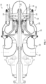
FIG. 1 is a schematic cross-sectional view of a gas turbine engine; -
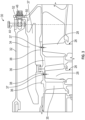
FIGS. 2 and3 are enlarged views of portions of the gas turbine engine as illustrated inFIG. 1 ; -
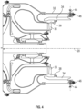
FIG. 4 is a cross-sectional view of a portion of the gas turbine engine illustrated inFIG. 1 ; -
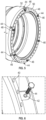
FIG. 5 is a perspective view of a portion of the gas turbine engine illustrated inFIG. 1 ; -
FIG. 6 illustrates a portion of the gas turbine illustrated inFIG. 1 ; -
FIG. 7 is a perspective cross-sectional view of a portion of the gas turbine illustrated inFIG. 1 ; -
FIG. 8 is a cross-sectional view of a portion of the gas turbine illustrated inFIG. 1 in accordance with an alternative embodiment; -
FIG. 8A illustrates set screws used in the embodiment illustrated inFIG. 8 ; -
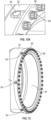
FIGS. 9 and10 illustrate a method for adjusting a tip clearance or for removing any eccentricity from the tip clearance of a gas turbine engine; and -
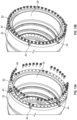
FIGS. 11-13B illustrate assembly of the adjustable housing to the outer structural case in accordance with the present disclosure. - A detailed description of one or more embodiments of the disclosed apparatus and method are presented herein by way of exemplification and not limitation with reference to the FIGS.
-
FIG. 1 illustrates agas turbine engine 10 of a type preferably provided for use in subsonic flight, generally comprising in serial flow communication acompressor section 14 for pressurizing the air, acombustor 16 in which the compressed air is mixed with fuel and ignited for generating an annular stream of hot combustion gases, and aturbine section 18 for extracting energy from the combustion gases. Some of the rotatable components of thegas turbine engine 10 rotate about alongitudinal center axis 20 of thegas turbine engine 10. - The
gas turbine engine 10 has a "cold"section 22 and a "hot"section 24. Thecold section 22 includes those components of thegas turbine engine 10 which are upstream (relative to the direction gases flow through the gas turbine engine 10) of thecombustor 16 and have thus not been exposed to the hot combustion gases. Thehot section 24 includes thecombustor 16 and those components of thegas turbine engine 10 which are downstream of thecombustor 16. The components of thehot section 24 are thus exposed to the hot combustion gases generated in thecombustor 16. The gases flowing through thecold section 22 have a lower temperature than the gases flowing through thehot section 24. - The
hot section 24 includes thecombustor 16, theturbine section 18 and a case downstream of theturbine section 18 for conveying the exhaust gases. Theturbine section 18 includes one ormore rotors 26 each having a plurality ofrotor blades 28 which rotate about thecenter axis 20 and extract energy from the combustion gases. Therotors 26 and therotor blades 28 of theturbine section 18 are typically referred to asturbines 26 andturbine blades 28, respectively. Thehot section 24 includes stationary bodies which enclose other components of thehot section 24 and define the gas path for the hot combustion gases. These stationary bodies are sometimes referred to as casings or cases which collectively define radially-outer boundaries of the gas turbine engine. - Referring now to at least
FIGS. 1-3 , the casing of thegas turbine engine 10 includes aturbine casing assembly 30 which is part of thehot section 24. Theturbine casing assembly 30 is a group of casing components that form part of theturbine section 18 and enclose the combustion gases. Theturbine casing assembly 30 may be provided as disassembled components which may then be assembled in a suitable facility. Theturbine casing assembly 30 includes an outerstructural case 32, anadjustable housing 34, and at least onevane ring 36. The at least onevane ring 36 having at least onevane 35 secured thereto. In one embodiment, the least onevane ring 36 having the at least onevane 35 is formed as a single component. Aportion 38 of the at least onevane ring 36 has a circular surface that defines a clearance ortip clearance 37 between a tip of theturbine blades 28 and theportion 38 of the at least onevane ring 36. In one embodiment, the outerstructural case 32, theadjustable housing 34, and the least onevane ring 36 have circular portions or configurations. - The at least one
vane ring 36 is secured to theadjustable housing 34 and theadjustable housing 34 is adjustable with respect to the outerstructural case 32 before it is secured to the outerstructural case 32. The outerstructural case 32 has a plurality ofsecurement openings 40 and a plurality ofadjustment openings 42. The plurality of adjustment openings extending completely through a periphery of the outerstructural case 32. The plurality ofadjustment openings 42 are orthogonally positioned with respect to the plurality ofsecurement openings 40. In addition, the plurality ofadjustment openings 42 are also orthogonally positioned with respect to theengine axis 20. In one non-limiting embodiment, the plurality ofadjustment openings 42 and the plurality ofsecurement openings 40 are threaded openings. It being understood that the plurality ofadjustment openings 42 and the plurality ofsecurement openings 40 are offset from each other such that the plurality ofadjustment openings 42 and the plurality ofsecurement openings 40 do not intersect with each other. In order to relocate the at least onevane ring 36 with respect to the tips of the plurality ofturbine blades 28 such that thetip clearance 37 is uniform and not eccentric with respect to the plurality ofturbine blades 28, a plurality of adjustment members orbolts 44 are inserted into the plurality ofadjustment openings 42 until they contact theadjustable housing 34. - The plurality of
adjustment openings 42 are located about theengine axis 20 such that adjustment of their location with respect to the outerstructural case 32 after they contact theadjustable housing 34 will relocate theadjustable housing 34 with respect to theengine axis 20 such that the at least onevane ring 36 can be repositioned with respect to the tips of theplurality turbine vanes 28. For example, once theadjustment bolts 44 make contact with theadjustable housing 34 further rotation in a first direction or clockwise direction will push theadjustable housing 34 further away from the outerstructural case 32 or alternatively rotation of theadjustment bolt 44 in a second direction or counter clockwise direction will allow theadjustable housing 34 to be moved closed to the outerstructural case 32 by for example, rotatingother adjustment bolts 44 located on an opposite side of theengine axis 20 in the first direction or clockwise direction. - In one non limiting embodiment, the outer
structural case 32 hasflat surfaces 45 adjacent to the plurality ofadjustment openings 42. - In one non-limiting embodiment, there are at least six
adjustment openings 42 spaced equally about theengine axis 20. Of course, various embodiments of the present disclosure contemplate more or less than sixadjustment openings 42. - Once the
adjustable housing 34 is positioned in a desired location with respect to theengine axis 20, a first plurality ofsecurement bolts 46 are inserted throughopenings 48 in aflange 50 of theadjustable housing 34 that is positioned adjacent to anend surface 52 of the outerstructural case 32 that has the plurality ofsecurement openings 40 located within theadjustable housing 34. Once thesecurement bolts 46 are received in the plurality ofsecurement openings 40 theadjustable housing 34 is secured to the outerstructural case 32. Thereafter, the plurality ofadjustment bolts 44 may be removed and replaced with a second plurality ofsecurement bolts 54 that have a shorter shaft so that they do not extend from the outerstructural case 32. See at leastFIGS. 11 ,12 and 12A . - Referring now to at least
FIGS. 8 and 8A and in an alternative embodiment, the plurality of adjustment members orbolts 44 may be replaced with setscrews 56. The set screws 56 will be able to extend further into the plurality ofadjustment openings 42 thereby negating the need to replace them withshorter securement bolts 54 once theadjustable housing 34 is positioned in the desired location with respect to the plurality ofturbine blades 28. - Referring now to at least
FIGS. 4-13B , the assembly procedure of theturbine casing assembly 30, is described. First, the at least onevane ring 36 is secured to theadjustable housing 34. Then theadjustable housing 34 with the at least onevane ring 36 is inserted within the outerstructural case 32. Thereafter, theadjustment bolts 44 or theset screws 56 are threaded into theadjustment openings 42 until a distal end of theadjustment bolts 44 or theset screws 56 contacts theadjustable housing 34. It being understood that, an outer periphery of theadjustable housing 34 is slightly smaller than an inner periphery of the outerstructural case 32 such that once theadjustment bolts 44 or theset screws 56 pass through theadjustment openings 42 the distal ends of theadjustment bolts 44 contact theadjustable housing 34. - Once this occurs, an
indicator tool 58 is located on an end of aturbine shaft 60 at an interface of an inner bore of the of a disc of theturbine rotor 26. Adial indicator 62 of theindicator tool 58 is located against the diameter or tip of theturbine blade 28 that is to be used to control the tip clearance. Thereafter, theturbine shaft 60 is rotated to determine the eccentricity of the tip clearance of theturbine blade 28 with respect to the at least onevane ring 36. If an eccentric tip clearance is detected thenadjustment bolts 44 or theset screws 56 are adjusted (e.g., rotated clockwise or counter clockwise in order to allow for movement of theadjustable housing 34 with respect to the outer structural case 32) to remove any eccentricity from the tip clearance. Once this has been completed, theturbine shaft 60 is again rotated to determine the eccentricity of the tip clearance of theturbine blade 28 with respect to the at least onevane ring 36. If an eccentric tip clearance is detected thenadjustment bolts 44 or theset screws 56 are adjusted to remove any eccentricity from the tip clearance. If no eccentric tip clearance is detected, then thesecurement bolts 46 are received in the plurality ofsecurement openings 40 and theadjustable housing 34 is secured to the outerstructural case 32. See at leastFIGS. 13A and 13B . - Thereafter and as mentioned above, the
adjustment bolts 44 are removed and replaced withsecurement bolts 54 that have a shorter shaft unless set screws 56 are used. - The term "about" is intended to include the degree of error associated with measurement of the particular quantity based upon the equipment available at the time of filing the application. For example, "about" can include a range of ± 8% or 5%, or 2% of a given value.
- The terminology used herein is for the purpose of describing particular embodiments only and is not intended to be limiting of the present disclosure. As used herein, the singular forms "a", "an" and "the" are intended to include the plural forms as well, unless the context clearly indicates otherwise. It will be further understood that the terms "comprises" and/or "comprising," when used in this specification, specify the presence of stated features, integers, steps, operations, elements, and/or components, but do not preclude the presence or addition of one or more other features, integers, steps, operations, element components, and/or groups thereof.
- While the present disclosure has been described with reference to an exemplary embodiment or embodiments, it will be understood by those skilled in the art that various changes may be made and equivalents may be substituted for elements thereof without departing from the scope of the present disclosure. In addition, many modifications may be made to adapt a particular situation or material to the teachings of the present disclosure without departing from the essential scope thereof. Therefore, it is intended that the present disclosure not be limited to the particular embodiment disclosed as the best mode contemplated for carrying out this present disclosure, but that the present disclosure will include all embodiments falling within the scope of the claims.
Claims (15)
- An outer structural case (32) of a turbine casing assembly (30), the outer structural case (32) comprising:a plurality of threaded adjustment openings (42) located about a periphery of the outer structural case (32), the plurality of threaded adjustment openings (42) extending completely through the periphery of the outer structural case (32); anda plurality of threaded securement openings (40) arranged orthogonally with respect to the plurality of adjustment openings (42).
- The outer structural case (32) as in claim 1, wherein the plurality of threaded securement openings (40) are located on an end surface (52) of the outer structural case (32).
- The outer structural case (32) as in claim 1 or 2, wherein the outer structural case (32) has a circular configuration and the plurality of threaded adjustment openings (42) are orthogonally arranged with respect to a center axis (20) of the outer structural case (32).
- A turbine casing assembly (30) comprising:the outer structural case (32) of any preceding claim;an adjustable housing (34) located within the outer structural case (32);a plurality of adjustment members (44;56) rotatably received within the plurality of threaded adjustment openings (42), wherein a distal end of each one of the plurality of adjustment members (44;56) is in contact with the adjustable housing (34) when the plurality of adjustment members (44;56) are received within the plurality of threaded adjustment openings (42);at least one vane ring (36) secured to the adjustable housing (34), a portion (38) of the at least one vane ring (36) having a circular surface; anda rotor (26) having a plurality of turbine blades (28), wherein a clearance (37) between the circular surface and tips of the plurality of turbine blades (28) is adjustable by rotational movement of the plurality of adjustment members (44;56) when they are in contact with the adjustable housing (34).
- The turbine casing assembly (30) as in claim 4, wherein the at least one vane ring (36) comprises at least one vane (35).
- The turbine casing assembly (30) as in claim 4 or 5, further comprising a plurality of securement bolts (46) received in the plurality of threaded securement openings in order to secure the adjustable housing (34) to the outer structural case (32).
- The turbine casing assembly (30) as in claim 6, wherein the plurality of securement bolts (46) are inserted through openings (48) in a flange (50) of the adjustable housing (34) in order to secure the adjustable housing (34) to the outer structural case (32).
- The turbine casing assembly (30) as in claim 7, wherein the flange (50) is positioned adjacent to an end surface (52) of the outer structural case (32) when the adjustable housing (34) is secured to the outer structural case (32).
- The turbine casing assembly (30) as in any of claims 4 to 8, wherein the plurality of adjustment members (44;56) are bolts (44).
- The turbine casing assembly (30) as in any of claims 4 to 8, wherein the plurality of adjustment members (44;56) are set screws (56).
- A method of setting a tip clearance (37) in a turbine casing assembly (30), comprising:securing at least one vane ring (36) to an adjustable housing (34) of the turbine casing assembly (30), a portion (38) of the at least one vane ring (36) having a circular surface;positioning the adjustable housing (34) within an outer structural case (32) of the turbine casing assembly (30);adjusting a location of the adjustable housing (34) with respect to the outer structural case (32) by rotating a plurality of adjustment members (44;56) threadably received within a plurality of threaded adjustment openings (42) located about a periphery of the outer structural case (32), the plurality of threaded adjustment openings (42) extending completely through the periphery of the outer structural case (32), a distal end of each one of the plurality of adjustment members (44;56) making contact with the adjustable housing (32) when the plurality of adjustment members (44;56) are received within the plurality of threaded adjustment openings (42); andsecuring the adjustable housing (34) to the outer structural case (32) by inserting a first plurality of securement bolts (46) into a plurality of threaded securement openings (40) located within the outer structural case (32) after the adjusting step, wherein the plurality of threaded securement openings (40) are arranged orthogonally with respect to the plurality of threaded adjustment openings (42).
- The method as in claim 11, wherein the first plurality of securement bolts (46) pass through openings (48) in a flange (50) of the adjustable housing (34), the flange (50) being positioned adjacent to an end surface (52) of the outer structural case (32) when the adjustable housing (34) is secured to the outer structural case (32).
- The method as in claim 11 or 12, wherein the plurality of adjustment members (44;56) are a plurality of adjustment bolts (44) and the method further comprises the step of replacing the plurality of adjustment bolts (44) with a second plurality of securement bolts (54) after the securing step, the second plurality of securement bolts (54) having a shaft that is shorter than a shaft of the plurality of adjustment bolts (44).
- The method as in claim 11 or 12, wherein the plurality of adjustment members (44;56) are set screws (56).
- The method as in any of claims 11 to 14, further comprising the step of using an indicator tool (58) to measure a tip clearance (37) between the circular surface of the at least one vane ring (36) and tips of a plurality of turbine blades (28) rotatably received within the at least one vane ring (36).
Applications Claiming Priority (1)
| Application Number | Priority Date | Filing Date | Title |
|---|---|---|---|
| US18/219,288 US20250012200A1 (en) | 2023-07-07 | 2023-07-07 | Structural casing for gas turbine engine and method for adjusting tip clearance in a gas turbine engine |
Publications (1)
| Publication Number | Publication Date |
|---|---|
| EP4495388A1 true EP4495388A1 (en) | 2025-01-22 |
Family
ID=91853755
Family Applications (1)
| Application Number | Title | Priority Date | Filing Date |
|---|---|---|---|
| EP24186611.0A Pending EP4495388A1 (en) | 2023-07-07 | 2024-07-04 | Structural casing for gas turbine engine and method for adjusting tip clearance in a gas turbine engine |
Country Status (3)
| Country | Link |
|---|---|
| US (1) | US20250012200A1 (en) |
| EP (1) | EP4495388A1 (en) |
| CA (1) | CA3241823A1 (en) |
Citations (4)
| Publication number | Priority date | Publication date | Assignee | Title |
|---|---|---|---|---|
| US3062497A (en) * | 1958-11-24 | 1962-11-06 | Ford Motor Co | Gas turbine engine |
| US3628884A (en) * | 1970-06-26 | 1971-12-21 | Westinghouse Electric Corp | Method and apparatus for supporting an inner casing structure |
| US3841787A (en) * | 1973-09-05 | 1974-10-15 | Westinghouse Electric Corp | Axial flow turbine structure |
| US20130017082A1 (en) * | 2011-07-13 | 2013-01-17 | General Electric Company | Assembly for aligning an inner shell of a turbine casing |
-
2023
- 2023-07-07 US US18/219,288 patent/US20250012200A1/en active Pending
-
2024
- 2024-06-17 CA CA3241823A patent/CA3241823A1/en active Pending
- 2024-07-04 EP EP24186611.0A patent/EP4495388A1/en active Pending
Patent Citations (4)
| Publication number | Priority date | Publication date | Assignee | Title |
|---|---|---|---|---|
| US3062497A (en) * | 1958-11-24 | 1962-11-06 | Ford Motor Co | Gas turbine engine |
| US3628884A (en) * | 1970-06-26 | 1971-12-21 | Westinghouse Electric Corp | Method and apparatus for supporting an inner casing structure |
| US3841787A (en) * | 1973-09-05 | 1974-10-15 | Westinghouse Electric Corp | Axial flow turbine structure |
| US20130017082A1 (en) * | 2011-07-13 | 2013-01-17 | General Electric Company | Assembly for aligning an inner shell of a turbine casing |
Also Published As
| Publication number | Publication date |
|---|---|
| CA3241823A1 (en) | 2025-10-30 |
| US20250012200A1 (en) | 2025-01-09 |
Similar Documents
| Publication | Publication Date | Title |
|---|---|---|
| EP2169181B1 (en) | Gas turbine engine rotor and balance weight therefor | |
| EP1655457A1 (en) | Gas turbine engine and method of assembling same | |
| EP3650636B1 (en) | Gas turbine engine having a trim balance | |
| EP3686399A1 (en) | Geared turbofan with overspeed protection | |
| EP3584406B1 (en) | Clip and pin balance for rotor | |
| EP3760835B1 (en) | Combustor mounting structures for gas turbine engines | |
| GB2457060A (en) | Rotor with balance mass | |
| GB2463354A (en) | Stator ring configuration | |
| US12612863B2 (en) | Test blade for gas turbine engine and method of making | |
| US20250012200A1 (en) | Structural casing for gas turbine engine and method for adjusting tip clearance in a gas turbine engine | |
| EP4592503A1 (en) | Containment ring for gas turbine engine | |
| US20250020064A1 (en) | Test blade for gas turbine engine and method of making | |
| EP4512995A2 (en) | Counter-weight for use with a rotor module, rotor module and method for zeroing out a center of gravity of a plurality of blades with respect to an axis of a rotor disk the plurality of blades are secured to | |
| US10883370B2 (en) | Dovetail weight system for rotor balance | |
| EP3940198B1 (en) | Multi-ring spacer for gas turbine engine rotor stack assembly | |
| EP4512994A2 (en) | Rotor module and method for zeroing out a center of gravity of a plurality of blades with respect to an axis of a rotor disk the plurality of blades are secured to | |
| EP3450689A1 (en) | Fan hub attachment for leading and trailing edges of fan blades | |
| US12404780B2 (en) | Containment ring for gas turbine engine | |
| EP4592505A1 (en) | Containment ring for gas turbine engine | |
| EP3450688B1 (en) | Gas turbine engine and method for reducing blade off loads | |
| EP3771805A1 (en) | Diffuser case heatshields for gas turbine engines | |
| CA3262602A1 (en) | Containment ring for gas turbine engine |
Legal Events
| Date | Code | Title | Description |
|---|---|---|---|
| PUAI | Public reference made under article 153(3) epc to a published international application that has entered the european phase |
Free format text: ORIGINAL CODE: 0009012 |
|
| STAA | Information on the status of an ep patent application or granted ep patent |
Free format text: STATUS: THE APPLICATION HAS BEEN PUBLISHED |
|
| AK | Designated contracting states |
Kind code of ref document: A1 Designated state(s): AL AT BE BG CH CY CZ DE DK EE ES FI FR GB GR HR HU IE IS IT LI LT LU LV MC ME MK MT NL NO PL PT RO RS SE SI SK SM TR |
|
| STAA | Information on the status of an ep patent application or granted ep patent |
Free format text: STATUS: REQUEST FOR EXAMINATION WAS MADE |
|
| 17P | Request for examination filed |
Effective date: 20250722 |