EP4495385A1 - Integrally bladed rotor with increased rim bending stiffness - Google Patents
Integrally bladed rotor with increased rim bending stiffness Download PDFInfo
- Publication number
- EP4495385A1 EP4495385A1 EP24189469.0A EP24189469A EP4495385A1 EP 4495385 A1 EP4495385 A1 EP 4495385A1 EP 24189469 A EP24189469 A EP 24189469A EP 4495385 A1 EP4495385 A1 EP 4495385A1
- Authority
- EP
- European Patent Office
- Prior art keywords
- platform
- bladed rotor
- integrally bladed
- projection
- axial
- Prior art date
- Legal status (The legal status is an assumption and is not a legal conclusion. Google has not performed a legal analysis and makes no representation as to the accuracy of the status listed.)
- Pending
Links
Images


Classifications
-
- F—MECHANICAL ENGINEERING; LIGHTING; HEATING; WEAPONS; BLASTING
- F01—MACHINES OR ENGINES IN GENERAL; ENGINE PLANTS IN GENERAL; STEAM ENGINES
- F01D—NON-POSITIVE DISPLACEMENT MACHINES OR ENGINES, e.g. STEAM TURBINES
- F01D5/00—Blades; Blade-carrying members; Heating, heat-insulating, cooling or antivibration means on the blades or the members
- F01D5/34—Rotor-blade aggregates of unitary construction, e.g. formed of sheet laminae
-
- F—MECHANICAL ENGINEERING; LIGHTING; HEATING; WEAPONS; BLASTING
- F01—MACHINES OR ENGINES IN GENERAL; ENGINE PLANTS IN GENERAL; STEAM ENGINES
- F01D—NON-POSITIVE DISPLACEMENT MACHINES OR ENGINES, e.g. STEAM TURBINES
- F01D5/00—Blades; Blade-carrying members; Heating, heat-insulating, cooling or antivibration means on the blades or the members
- F01D5/02—Blade-carrying members, e.g. rotors
- F01D5/06—Rotors for more than one axial stage, e.g. of drum or multiple disc type; Details thereof, e.g. shafts, shaft connections
-
- F—MECHANICAL ENGINEERING; LIGHTING; HEATING; WEAPONS; BLASTING
- F01—MACHINES OR ENGINES IN GENERAL; ENGINE PLANTS IN GENERAL; STEAM ENGINES
- F01D—NON-POSITIVE DISPLACEMENT MACHINES OR ENGINES, e.g. STEAM TURBINES
- F01D5/00—Blades; Blade-carrying members; Heating, heat-insulating, cooling or antivibration means on the blades or the members
- F01D5/12—Blades
- F01D5/14—Form or construction
- F01D5/147—Construction, i.e. structural features, e.g. of weight-saving hollow blades
-
- F—MECHANICAL ENGINEERING; LIGHTING; HEATING; WEAPONS; BLASTING
- F04—POSITIVE - DISPLACEMENT MACHINES FOR LIQUIDS; PUMPS FOR LIQUIDS OR ELASTIC FLUIDS
- F04D—NON-POSITIVE-DISPLACEMENT PUMPS
- F04D29/00—Details, component parts, or accessories
- F04D29/26—Rotors specially for elastic fluids
- F04D29/32—Rotors specially for elastic fluids for axial flow pumps
- F04D29/321—Rotors specially for elastic fluids for axial flow pumps for axial flow compressors
-
- F—MECHANICAL ENGINEERING; LIGHTING; HEATING; WEAPONS; BLASTING
- F05—INDEXING SCHEMES RELATING TO ENGINES OR PUMPS IN VARIOUS SUBCLASSES OF CLASSES F01-F04
- F05D—INDEXING SCHEME FOR ASPECTS RELATING TO NON-POSITIVE-DISPLACEMENT MACHINES OR ENGINES, GAS-TURBINES OR JET-PROPULSION PLANTS
- F05D2220/00—Application
- F05D2220/30—Application in turbines
- F05D2220/32—Application in turbines in gas turbines
- F05D2220/323—Application in turbines in gas turbines for aircraft propulsion, e.g. jet engines
-
- F—MECHANICAL ENGINEERING; LIGHTING; HEATING; WEAPONS; BLASTING
- F05—INDEXING SCHEMES RELATING TO ENGINES OR PUMPS IN VARIOUS SUBCLASSES OF CLASSES F01-F04
- F05D—INDEXING SCHEME FOR ASPECTS RELATING TO NON-POSITIVE-DISPLACEMENT MACHINES OR ENGINES, GAS-TURBINES OR JET-PROPULSION PLANTS
- F05D2230/00—Manufacture
- F05D2230/50—Building or constructing in particular ways
- F05D2230/53—Building or constructing in particular ways by integrally manufacturing a component, e.g. by milling from a billet or one piece construction
-
- F—MECHANICAL ENGINEERING; LIGHTING; HEATING; WEAPONS; BLASTING
- F05—INDEXING SCHEMES RELATING TO ENGINES OR PUMPS IN VARIOUS SUBCLASSES OF CLASSES F01-F04
- F05D—INDEXING SCHEME FOR ASPECTS RELATING TO NON-POSITIVE-DISPLACEMENT MACHINES OR ENGINES, GAS-TURBINES OR JET-PROPULSION PLANTS
- F05D2240/00—Components
- F05D2240/80—Platforms for stationary or moving blades
-
- F—MECHANICAL ENGINEERING; LIGHTING; HEATING; WEAPONS; BLASTING
- F05—INDEXING SCHEMES RELATING TO ENGINES OR PUMPS IN VARIOUS SUBCLASSES OF CLASSES F01-F04
- F05D—INDEXING SCHEME FOR ASPECTS RELATING TO NON-POSITIVE-DISPLACEMENT MACHINES OR ENGINES, GAS-TURBINES OR JET-PROPULSION PLANTS
- F05D2260/00—Function
- F05D2260/94—Functionality given by mechanical stress related aspects such as low cycle fatigue [LCF] of high cycle fatigue [HCF]
Definitions
- the disclosure relates generally to aircraft engines and, more particularly, to integrally bladed rotors for aircraft engines.
- Aircraft rotor assemblies rotate at extreme speeds and may be subjected to various stresses associated with low-cycle-fatigue (LCF), for instance due to centrifugal and thermal loads, and vibratory stresses associated with high-cycle-fatigue (HCF) occurring at resonance conditions.
- LCF low-cycle-fatigue
- HCF high-cycle-fatigue
- an integrally bladed rotor for an aircraft engine comprising: a hub; a circumferential array of blades extending from the hub, each blade having an airfoil extending from a gaspath side of a platform provided at a periphery of the hub, the platform having a radial thickness T, an edge of the airfoil disposed at an axial distance L 1 from an adjacent axial edge of the platform; and a projection extending radially inwardly from an interior side of the platform opposite to the gaspath side, the projection having an axial thickness t, a radial height h from the interior side of the platform, and an axial distance L 2 from the adjacent axial edge of the platform; wherein T is a radial thickness of the platform at an axial location of the projection; and wherein 0.2 ⁇ T t ⁇ 5 ; 1 ⁇ h t ⁇ 10 ; and 0 ⁇ L 2 L 1 ⁇ 10 .
- the projection extends uninterruptedly about a circumference of the interior side of the platform.
- the projection includes one or more cutouts defined in a radially inner edge of the projection.
- the one or more cutouts are scallop-shaped.
- the one or more cutouts are circumferentially disposed between adjacent blades of the circumferential array of blades.
- the integrally bladed rotor is a high pressure compressor for the aircraft engine.
- an aircraft engine comprising: a shaft rotatable about an axis; and an integrally bladed rotor mounted to the shaft for rotation therewith, the integrally bladed rotor including: a hub having a radially outer rim, the radially outer rim having a gaspath side and an interior side opposite to the gaspath side; a circumferential array of blades extending from the gaspath side of the radially outer rim; and a rib extending radially inwardly from the interior side of the radially outer rim, the rim axially aligned with one of a leading edge and a trailing edge of the circumferential array of blades, wherein: 0.2 ⁇ T t ⁇ 5 ; 1 ⁇ h t ⁇ 10 ; and wherein T is a radial thickness of the radially outer rim at a location of the rib, t is an axial thickness of the rib, and h a radial height
- the one of the leading edge or the trailing edge of the circumferential array of blades is disposed at an axial distance L 1 from an adjacent axial edge of the radially outer rim, the rib axially spaced from the adjacent axial edge of the radially outer rim by an axial distance L 2 , and wherein 0.5 ⁇ L 2 L 1 ⁇ 1.5 .
- rib extends uninterruptedly about a circumference of the interior side of the radially outer rim.
- the rib includes one or more cutouts defined in a radially inner edge of the rib.
- the one or more cutouts are scallop-shaped.
- the one or more cutouts are circumferentially disposed between adjacent blades of the circumferential array of blades.
- the aircraft engine comprises a compressor section and a turbine section, and wherein the integrally bladed rotor is part of the compressor section.
- integrally bladed rotor for an aircraft engine comprising: a one-piece body including a plurality of blades extending integrally from a gaspath side of a platform, and a rib projecting integrally from an interior side of the platform opposite to the gaspath side; wherein: 0.5 ⁇ T t ⁇ 3 ; 2 ⁇ h t ⁇ 8 ; and 2 ⁇ L 2 L 1 ⁇ 8 ; and wherein T is a radial thickness of the platform at an axial location of the rib, t is an axial thickness of the rib, h a radial height of the rib from the interior side of the platform, L 1 is an axial distance from a leading edge of the plurality of blades to an adjacent leading edge of the platform, and L 2 is an axial distance from the rib to the leading edge of the platform.
- the rib extends circumferentially uninterruptedly along the interior side of the platform, and wherein circumferentially spaced-apart scallops are defined in a radially inner edge of the rib, the circumferentially spaced-apart scallops disposed between adjacent blades of the plurality of blades.
- FIG. 1 schematically depicts a turbofan engine A which, as an example, illustrates the application of the described subject matter.
- the turbofan engine A includes a nacelle 10, a low pressure spool assembly which includes at least a fan 12 and a low pressure turbine 14 connected by a low pressure shaft 16, and a high pressure spool which includes a high pressure compressor 18 and a high pressure turbine 20 connected by a high pressure shaft 22, extending about a central longitudinal axis CL.
- the engine A further comprises a combustor 26.
- the fan 12, the high pressure compressor 18, the high pressure turbine 20 and the low pressure turbine 14, for the purposes of the present description include rotors represented by the blades 30 in FIG. 1 . While FIG. 1 illustratively depicts engine A as a turbofan engine, other types of gas turbine engines, as well as hybrid-electric engines, may be contemplated.
- the rotors for instance the fan 12 or the high pressure compressor 18, may be provided in the form of blisks, that is, in the form of integrally bladed rotors (IBR).
- IBR integrally bladed rotors
- Rotor B for engine A is shown.
- Rotor B may, for instance, be high pressure compressor 18, although other rotors of engine A may be contemplated, such as fan 12, high pressure turbine 20, or low pressure turbine 14.
- Rotor B includes a circumferential array of blades 30 integrally formed with and extending from a rotor hub 34 in a unitary construction. Each blade 30 comprises an airfoil 32 extending from a gas path side (shown in FIGS.
- annular platform 34a also referred to as a rim, formed at the periphery of the rotor hub 34.
- the number and shape of the blades 30 may vary, for instance based on the engine A type and/or rotor B type.
- the hub 34 includes a radially inner portion 34b with a central bore 36 configured for mounting to an engine shaft, for instance low pressure shaft 16 or high pressure shaft 22.
- LCF low-cycle fatigue
- HCF high-cycle fatigue
- FOD foreign object damage
- a projection 38 also referred to as a stiffening rib, extends radially inwardly from an interior side 34d of the platform 34a.
- the projection 38 is configured for increasing the bending stiffness of the platform 34a, thereby reducing the risk of crack formation and propagation in the rotor B.
- the projection 38 may be disposed beneath or adjacent a critical location of the rotor B (i.e., where a crack is most likely to form), thereby providing additional stiffness where it may needed most.
- the stiffening rib or projection 38 is shown to be spaced axially inwardly from a front edge 34c of the platform 34a and is axially aligned with a leading edge 32a of the airfoil 32.
- a projection 38 could be similarly disposed underneath the trailing edge of the airfoil 32 at an axial distance inboard from the aft edge of the platform 34a.
- such projections or ribs may extend in a direction generally normal to the interior side of the platform 34a, although other directions may be contemplated.
- Various shapes and sizes of the projection 38 are contemplated.
- the platform 34a has a local radial thickness T at the axial location of the projection 38.
- the leading edge 32a of the airfoil 32 meets the platform 34a at an axial distance L 1 from the front edge 34c of the platform 34a.
- the projection 38 has an axial thickness t, a radial height h from the interior side 34d of the platform 34a, and an axial distance L 2 from the front edge 34c of platform 34a.
- the axial thickness t of the projection may refer to its average axial thickness, although other reference thicknesses (e.g., its maximum axial thickness) may be contemplated.
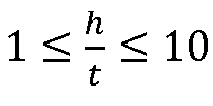
- the projection 38 may respect the following ranges for the following ratios: 0.2 ⁇ T t ⁇ 5 1 ⁇ h t ⁇ 10 0 ⁇ L 2 L 1 ⁇ 10
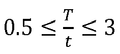
- the projection 38 may additionally respect one or more of the following sub-ranges: 0.5 ⁇ T t ⁇ 3 . 2 ⁇ h t ⁇ 8 . 2 ⁇ L 2 L 1 ⁇ 8 .
- the radial thickness T of the platform 34a may be said to be an independent parameter of a given rotor B, whereas the axial thickness t of the projection 38 may be subsequently selected based on the radial thickness T for a pre-selected stiffness of the platform 34a.
- a T / t ratio below 0.2 may result in a platform 34a with an increased stiffness but a non-negligible weight increase, thereby potentially minimizing the practicality of the projection 38.
- a T/t ratio above 5 may result in a lighter projection 38, albeit potentially providing less stiffness gain than desired.
- a T / t ratio between 0.2 and 5 may thus provide a balance between weight gain and increased stiffness.
- Other ranges may be contemplated, for instance based on the number and type of projections 38 and the selected materials.
- an h / t ratio below 1 may, in some applications, provide a minimal increase in stiffness to the platform 34a, whereas an h / t ratio above 10 may create a discernable weight increase.
- a h / t ratio between 1 and 10 may thus provide a balance between weight gain and increased stiffness.
- Other ranges may be contemplated, for instance based on the number and type of projections 38 and the selected materials.
- the additional stiffness may be provided where a crack is most likely to initiate, which may be at the L 1 location.
- a L 2 / L 1 ratio of approximately 1 i.e., the projection 38 axially aligned with the leading edge 32a of the airfoil 32) may provide adequate stiffness to the platform 34a.
- the location where stress concentrations would be highest may vary (for instance, based on the size and/or shape of the airfoil), and as such the preferred L 2 / L 1 ratio may vary from 0 (i.e., the projection 38 axially disposed at the edge 34c of the platform 34a) to 10 (i.e., the projection 38 disposed near a web of the hub 34).
- Other L 2 / L 1 ratios may be contemplated, for instance based on the number and type of projections 38 and the selected materials.
- the projection 38 may be integrally formed with the platform 34a.
- the projection 38 is circumferentially continuous about the inner side 34d of the platform 34a.
- Cutouts 38b illustratively circumferentially spaced-apart scalloped-shaped cutouts 38b, may be provided in the radially inner edge of the projection 38 for increased balancing and/or reduced weight.
- one or more axial through holes may be provided through the projection 38.
- the circumferential locations of the cutouts 38b (or holes) may be selected, for instance, to be misaligned with the blades 30 (i.e., circumferentially disposed between adjacent blades 30), for instance to ensure full projection 38 thickness (and thus structural integrity) at the locations of the blades 30.
- a plurality of circumferentially spaced apart projections 38 may be provided in annular alignment, interrupted by circumferential voids or spaces.
- the projections 38 may be circumferentially aligned with the blades 30 so as to provide structural reinforcement at the circumferential locations of the blades 30.
- Other locations for the projections 38 and the voids may be contemplated.
- two or more rows of projections 38 i.e., axially spaced apart from one another from the edge 34c of the platform 34a, may be provided.
- the rows of projections 38 may be configured to provide additional stiffness at desired locations of the platform 34a.
- a first row of projections 38 may be continuous about its circumference, while a second row of projections 38 may include a plurality of circumferentially spaced apart projections 38 in annular alignment, interrupted by voids or spaces. Oher combinations of continuous and non-continuous projections 38 may be contemplated.
- the integrally bladed rotor B includes a circumferential array of blades 30 extending from a hub 34, each blade 30 having an airfoil 32 extending from a gaspath side of a platform 34a provided at a periphery of the hub 34, the platform 34a having a radial thickness T, an edge 32a of the airfoil 32 disposed at an axial distance L 1 from an adjacent axial edge 34c of the platform 34a.
- the method includes providing a projection 38 extending radially inwardly from an interior side 34d of the platform 34a, the projection 38 having an axial thickness t, a radial height h from the interior side 34d of the platform 34a, and an axial distance L 2 from the adjacent axial edge 34c of the platform 34d, wherein 0.2 ⁇ T t ⁇ 5 , 1 ⁇ h t ⁇ 10 , and 0 ⁇ L 2 L 1 ⁇ 10 .
- any maximum value, minimum value and/or ranges of values provided herein include(s) all values falling within the applicable manufacturing tolerances. Accordingly, in certain instances, these values may be varied by t 5%. In other implementations, these values may vary by as much as t 10%.
Landscapes
- Engineering & Computer Science (AREA)
- Mechanical Engineering (AREA)
- General Engineering & Computer Science (AREA)
- Ceramic Engineering (AREA)
- Architecture (AREA)
- Structures Of Non-Positive Displacement Pumps (AREA)
Abstract
An integrally bladed rotor (B) for an aircraft engine (A) includes a hub (34) and a circumferential array of blades (30) extending from the hub (34). Each blade (30) has an airfoil (32) extending from a gaspath side of a platform (34a) provided at a periphery of the hub (34). The platform (34a) has a radial thickness T. An edge (32a) of the airfoil (32) is disposed at an axial distance L1 from an adjacent axial edge (34c) of the platform (34a). A projection (38) extends radially inwardly from an interior side (34d) of the platform (34a) opposite to the gaspath side. The projection (38) has an axial thickness t, a radial height h from the interior side (34d) of the platform (34a), and an axial distance L2 from the adjacent axial edge (34c) of the platform. T is a radial thickness of the platform (34a) at an axial location of the projection (38), and 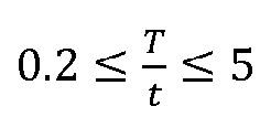
; 
; and 0 ≤ 
.
Description
- The disclosure relates generally to aircraft engines and, more particularly, to integrally bladed rotors for aircraft engines.
- Aircraft rotor assemblies rotate at extreme speeds and may be subjected to various stresses associated with low-cycle-fatigue (LCF), for instance due to centrifugal and thermal loads, and vibratory stresses associated with high-cycle-fatigue (HCF) occurring at resonance conditions. Such stresses may inadvertently lead to damage such as crack formation and propagation on the blades of the rotor, possibly to the rotor hub. It is thus desirable to reduce the risk of crack formation and propagation.
- In one aspect of the present invention, there is provided an integrally bladed rotor for an aircraft engine, comprising: a hub; a circumferential array of blades extending from the hub, each blade having an airfoil extending from a gaspath side of a platform provided at a periphery of the hub, the platform having a radial thickness T, an edge of the airfoil disposed at an axial distance L1 from an adjacent axial edge of the platform; and a projection extending radially inwardly from an interior side of the platform opposite to the gaspath side, the projection having an axial thickness t, a radial height h from the interior side of the platform, and an axial distance L2 from the adjacent axial edge of the platform; wherein T is a radial thickness of the platform at an axial location of the projection; and wherein


- In embodiments of the above,

- In embodiments of any of the above,

- In embodiments of any of the above,

- In embodiments of any of the above, the projection extends uninterruptedly about a circumference of the interior side of the platform.
- In embodiments of any of the above, the projection includes one or more cutouts defined in a radially inner edge of the projection.
- In embodiments of any of the above, the one or more cutouts are scallop-shaped.
- In embodiments of any of the above, the one or more cutouts are circumferentially disposed between adjacent blades of the circumferential array of blades.
- In embodiments of any of the above, the integrally bladed rotor is a high pressure compressor for the aircraft engine.
- In another aspect of the present invention, there is provided an aircraft engine, comprising: a shaft rotatable about an axis; and an integrally bladed rotor mounted to the shaft for rotation therewith, the integrally bladed rotor including: a hub having a radially outer rim, the radially outer rim having a gaspath side and an interior side opposite to the gaspath side; a circumferential array of blades extending from the gaspath side of the radially outer rim; and a rib extending radially inwardly from the interior side of the radially outer rim, the rim axially aligned with one of a leading edge and a trailing edge of the circumferential array of blades, wherein:


- In embodiments of the above, the one of the leading edge or the trailing edge of the circumferential array of blades is disposed at an axial distance L1 from an adjacent axial edge of the radially outer rim, the rib axially spaced from the adjacent axial edge of the radially outer rim by an axial distance L2 , and wherein

- In embodiments of any of the above,
- In embodiments of any of the above,

- In embodiments of any of the above the, rib extends uninterruptedly about a circumference of the interior side of the radially outer rim.
- In embodiments of any of the above, the rib includes one or more cutouts defined in a radially inner edge of the rib.
- In embodiments of any of the above the, the one or more cutouts are scallop-shaped.
- In embodiments of any of the above the, the one or more cutouts are circumferentially disposed between adjacent blades of the circumferential array of blades.
- In embodiments of any of the above the, the aircraft engine comprises a compressor section and a turbine section, and wherein the integrally bladed rotor is part of the compressor section.
- In a further aspect of the present invention, there is provided integrally bladed rotor for an aircraft engine, comprising: a one-piece body including a plurality of blades extending integrally from a gaspath side of a platform, and a rib projecting integrally from an interior side of the platform opposite to the gaspath side; wherein:


- In embodiments of the above, the rib extends circumferentially uninterruptedly along the interior side of the platform, and wherein circumferentially spaced-apart scallops are defined in a radially inner edge of the rib, the circumferentially spaced-apart scallops disposed between adjacent blades of the plurality of blades.
- Reference is now made to the accompanying figures in which:
-
FIG. 1 is a schematic cross sectional view of a gas turbine engine; -
FIG. 2 is a side view of a rotor for the engine ofFIG. 1 , according to an embodiment of the present disclosure; -
FIG. 3 is an enhanced front view of the rotor ofFIG. 2 ; and -
Fig. 4 is an enhanced side view of the rotor ofFIG. 2 . -
FIG. 1 schematically depicts a turbofan engine A which, as an example, illustrates the application of the described subject matter. The turbofan engine A includes anacelle 10, a low pressure spool assembly which includes at least afan 12 and alow pressure turbine 14 connected by alow pressure shaft 16, and a high pressure spool which includes ahigh pressure compressor 18 and ahigh pressure turbine 20 connected by ahigh pressure shaft 22, extending about a central longitudinal axis CL. The engine A further comprises acombustor 26. Thefan 12, thehigh pressure compressor 18, thehigh pressure turbine 20 and thelow pressure turbine 14, for the purposes of the present description include rotors represented by theblades 30 inFIG. 1 . WhileFIG. 1 illustratively depicts engine A as a turbofan engine, other types of gas turbine engines, as well as hybrid-electric engines, may be contemplated. - The rotors, for instance the
fan 12 or thehigh pressure compressor 18, may be provided in the form of blisks, that is, in the form of integrally bladed rotors (IBR). Referring toFIGS. 2 and3 , a rotor B for engine A is shown. Rotor B may, for instance, behigh pressure compressor 18, although other rotors of engine A may be contemplated, such asfan 12,high pressure turbine 20, orlow pressure turbine 14. Rotor B includes a circumferential array ofblades 30 integrally formed with and extending from arotor hub 34 in a unitary construction. Eachblade 30 comprises anairfoil 32 extending from a gas path side (shown inFIGS. 2 and3 ) of anannular platform 34a, also referred to as a rim, formed at the periphery of therotor hub 34. The number and shape of theblades 30 may vary, for instance based on the engine A type and/or rotor B type. Thehub 34 includes a radiallyinner portion 34b with acentral bore 36 configured for mounting to an engine shaft, for instancelow pressure shaft 16 orhigh pressure shaft 22. - As the rotor B rotates about the axis CL, various loads may cause damage to its various components. For instance, low-cycle fatigue (LCF) loads such as centrifugal forces and thermal loads, and high-cycle fatigue (HCF) loads such as dynamic loading occurring at resonance conditions due to aerodynamic excitation may undesirably cause cracks in the
blades 30. In an integrally bladed rotor such as rotor B, additional concerns may result if the cracks in theblades 30 were to propagate to thehub 34. Additionally or alternatively, cracks may initiate and/or propagate on thehub 34 itself, for instance due to interactions between LCF and HCF loads, and/or due to foreign object damage (FOD). Referring toFIGS. 3 and4 , to address this and other concerns, aprojection 38, also referred to as a stiffening rib, extends radially inwardly from aninterior side 34d of theplatform 34a. As will be discussed in further detail below, theprojection 38 is configured for increasing the bending stiffness of theplatform 34a, thereby reducing the risk of crack formation and propagation in the rotor B. By increasing the bending stiffness at areas susceptible to crack formation and/or propagation (e.g., at the base of an airfoil 32), the bending stresses ensuing from HCF-derived modes may be minimized, reducing the risk that the crack would form and/or propagate. Theprojection 38 may be disposed beneath or adjacent a critical location of the rotor B (i.e., where a crack is most likely to form), thereby providing additional stiffness where it may needed most. - Referring to
FIG. 4 , the stiffening rib orprojection 38 is shown to be spaced axially inwardly from afront edge 34c of theplatform 34a and is axially aligned with a leadingedge 32a of theairfoil 32. According some applications, aprojection 38 could be similarly disposed underneath the trailing edge of theairfoil 32 at an axial distance inboard from the aft edge of theplatform 34a. In some cases, such projections or ribs may extend in a direction generally normal to the interior side of theplatform 34a, although other directions may be contemplated. Various shapes and sizes of theprojection 38 are contemplated. In the shown case, theplatform 34a has a local radial thickness T at the axial location of theprojection 38. The leadingedge 32a of theairfoil 32 meets theplatform 34a at an axial distance L1 from thefront edge 34c of theplatform 34a. Theprojection 38 has an axial thickness t, a radial height h from theinterior side 34d of theplatform 34a, and an axial distance L2 from thefront edge 34c ofplatform 34a. In cases where the axial thickness t of the projection varies (e.g., tapers) along its radial height h, the axial thickness t may refer to its average axial thickness, although other reference thicknesses (e.g., its maximum axial thickness) may be contemplated. - To provide the
platform 34a with the desired additional stiffness to mitigate crack formation and/or crack propagation, theprojection 38 may respect the following ranges for the following ratios:


- In various embodiments, the
projection 38 may additionally respect one or more of the following sub-ranges:


- Other nested sub-ranges for the above parameters and ratios may be contemplated.
- With regards to the ratio T/t, the radial thickness T of the
platform 34a may be said to be an independent parameter of a given rotor B, whereas the axial thickness t of theprojection 38 may be subsequently selected based on the radial thickness T for a pre-selected stiffness of theplatform 34a. As such, a T/t ratio below 0.2 may result in aplatform 34a with an increased stiffness but a non-negligible weight increase, thereby potentially minimizing the practicality of theprojection 38. On the other hand, a T/t ratio above 5 may result in alighter projection 38, albeit potentially providing less stiffness gain than desired. A T/t ratio between 0.2 and 5 may thus provide a balance between weight gain and increased stiffness. Other ranges may be contemplated, for instance based on the number and type ofprojections 38 and the selected materials. - With regards to the ratio h/t, an h/t ratio below 1 may, in some applications, provide a minimal increase in stiffness to the
platform 34a, whereas an h/t ratio above 10 may create a discernable weight increase. A h/t ratio between 1 and 10 may thus provide a balance between weight gain and increased stiffness. Other ranges may be contemplated, for instance based on the number and type ofprojections 38 and the selected materials. - With regards to the ratio L2 /L1 , the additional stiffness may be provided where a crack is most likely to initiate, which may be at the L1 location. As such, a L2 /L1 ratio of approximately 1 (i.e., the
projection 38 axially aligned with theleading edge 32a of the airfoil 32) may provide adequate stiffness to theplatform 34a. In other cases, the location where stress concentrations would be highest may vary (for instance, based on the size and/or shape of the airfoil), and as such the preferred L2 /L1 ratio may vary from 0 (i.e., theprojection 38 axially disposed at theedge 34c of theplatform 34a) to 10 (i.e., theprojection 38 disposed near a web of the hub 34). Other L2 /L1 ratios may be contemplated, for instance based on the number and type ofprojections 38 and the selected materials. - The
projection 38 may be integrally formed with theplatform 34a. In the shown embodiment, theprojection 38 is circumferentially continuous about theinner side 34d of theplatform 34a.Cutouts 38b, illustratively circumferentially spaced-apart scalloped-shapedcutouts 38b, may be provided in the radially inner edge of theprojection 38 for increased balancing and/or reduced weight. - Additionally or alternatively, one or more axial through holes may be provided through the
projection 38. The circumferential locations of thecutouts 38b (or holes) may be selected, for instance, to be misaligned with the blades 30 (i.e., circumferentially disposed between adjacent blades 30), for instance to ensurefull projection 38 thickness (and thus structural integrity) at the locations of theblades 30. In other embodiments, a plurality of circumferentially spaced apart projections 38 (for instance, identically sized and shaped projections 38) may be provided in annular alignment, interrupted by circumferential voids or spaces. In such embodiments, theprojections 38 may be circumferentially aligned with theblades 30 so as to provide structural reinforcement at the circumferential locations of theblades 30. Other locations for theprojections 38 and the voids may be contemplated. - In other embodiments, two or more rows of
projections 38, i.e., axially spaced apart from one another from theedge 34c of theplatform 34a, may be provided. The rows ofprojections 38 may be configured to provide additional stiffness at desired locations of theplatform 34a. In some embodiments, a first row ofprojections 38 may be continuous about its circumference, while a second row ofprojections 38 may include a plurality of circumferentially spaced apartprojections 38 in annular alignment, interrupted by voids or spaces. Oher combinations of continuous andnon-continuous projections 38 may be contemplated. - In accordance with one or more embodiments of the present disclosure, there is provided a method for increasing the stiffness of an integrally bladed rotor B for an aircraft engine A. The integrally bladed rotor B includes a circumferential array of
blades 30 extending from ahub 34, eachblade 30 having anairfoil 32 extending from a gaspath side of aplatform 34a provided at a periphery of thehub 34, theplatform 34a having a radial thickness T, anedge 32a of theairfoil 32 disposed at an axial distance L1 from an adjacentaxial edge 34c of theplatform 34a. The method includes providing aprojection 38 extending radially inwardly from aninterior side 34d of theplatform 34a, theprojection 38 having an axial thickness t, a radial height h from theinterior side 34d of theplatform 34a, and an axial distance L2 from the adjacentaxial edge 34c of theplatform 34d, wherein


- In the present disclosure, when a specific numerical value is provided (e.g. as a maximum, minimum or range of values), it is to be understood that this value or these ranges of values may be varied, for example due to applicable manufacturing tolerances, material selection, etc. As such, any maximum value, minimum value and/or ranges of values provided herein (such as, for example only, the above-noted ranges for the ratios T/t, h/t and L 2/L1 ), include(s) all values falling within the applicable manufacturing tolerances. Accordingly, in certain instances, these values may be varied by t 5%. In other implementations, these values may vary by as much as
t 10%. A person of ordinary skill in the art will understand that such variances in the values provided herein may be possible without departing from the intended scope of the present disclosure, and will appreciate for example that the values may be influenced by the particular manufacturing methods and materials used to implement the claimed technology. - The embodiments described in this document provide non-limiting examples of possible implementations of the present technology. Upon review of the present disclosure, a person of ordinary skill in the art will recognize that changes may be made to the embodiments described herein without departing from the scope of the present technology. Yet further modifications could be implemented by a person of ordinary skill in the art in view of the present disclosure, which modifications would be within the scope of the present technology.
Claims (11)
- An integrally bladed rotor (B) for an aircraft engine (A), the integrally bladed rotor (B) comprising:a hub (34);a circumferential array of blades (30) extending from the hub (34), each blade (30) having an airfoil (32) extending from a gaspath side of a platform (34a) provided at a periphery of the hub (34), the platform (34a) having a radial thickness T, an edge (32a) of the airfoil (32) disposed at an axial distance L1 from an adjacent axial edge (34c) of the platform (34a); anda projection (38) extending radially inwardly from an interior side (34d) of the platform (34a) opposite to the gaspath side, the projection (38) having an axial thickness t, a radial height h from the interior side (34d) of the platform (34a), and an axial distance L2 from the adjacent axial edge (34c) of the platform (34a);wherein T is a radial thickness of the platform (34a) at an axial location of the projection (38); andwherein


- The integrally bladed rotor as defined in claim 1, wherein

- The integrally bladed rotor as defined in claim 1 or 2, wherein

- The integrally bladed rotor as defined in any of the preceding claims, wherein

- The integrally bladed rotor as defined in any of the preceding claims, wherein the projection (38) extends uninterruptedly about a circumference of the interior side (34d) of the platform (34a).
- The integrally bladed rotor as defined in any of the preceding claims, wherein the projection (38) includes one or more cutouts (38b) defined in a radially inner edge of the projection (38).
- The integrally bladed rotor as defined in claim 6, wherein the one or more cutouts (38b) are scallop-shaped.
- The integrally bladed rotor as defined in claim 6 or 7, wherein the one or more cutouts are circumferentially disposed between adjacent blades (30) of the circumferential array of blades (30).
- The integrally bladed rotor as defined in any of the preceding claims, wherein the integrally bladed rotor (B) is a high pressure compressor (18) for the aircraft engine (A).
- An aircraft engine (A), comprising:a shaft (16, 22) rotatable about an axis (CL); andan integrally bladed rotor (B) as defined in any of the preceding claims, the integrally bladed rotor (B) mounted to the shaft (16, 22) for rotation therewith.
- The aircraft engine as defined in claim 10, wherein the aircraft engine (A) comprises a compressor section (12, 18) and a turbine section (14, 20), and wherein the integrally bladed rotor (B) is part of the compressor section (12, 18).
Applications Claiming Priority (1)
| Application Number | Priority Date | Filing Date | Title |
|---|---|---|---|
| US18/354,714 US12228052B2 (en) | 2023-07-19 | 2023-07-19 | Integrally bladed rotor with increased rim bending stiffness |
Publications (1)
| Publication Number | Publication Date |
|---|---|
| EP4495385A1 true EP4495385A1 (en) | 2025-01-22 |
Family
ID=91959403
Family Applications (1)
| Application Number | Title | Priority Date | Filing Date |
|---|---|---|---|
| EP24189469.0A Pending EP4495385A1 (en) | 2023-07-19 | 2024-07-18 | Integrally bladed rotor with increased rim bending stiffness |
Country Status (3)
| Country | Link |
|---|---|
| US (1) | US12228052B2 (en) |
| EP (1) | EP4495385A1 (en) |
| CA (1) | CA3244617A1 (en) |
Citations (8)
| Publication number | Priority date | Publication date | Assignee | Title |
|---|---|---|---|---|
| US6494679B1 (en) * | 1999-08-05 | 2002-12-17 | General Electric Company | Apparatus and method for rotor damping |
| US20050186080A1 (en) * | 2004-02-24 | 2005-08-25 | Rolls-Royce Plc | Fan or compressor blisk |
| US7370787B2 (en) * | 2003-12-15 | 2008-05-13 | Pratt & Whitney Canada Corp. | Compressor rotor and method for making |
| US8888458B2 (en) * | 2012-03-12 | 2014-11-18 | United Technologies Corporation | Turbomachine rotor balancing system |
| US20150369049A1 (en) * | 2011-06-28 | 2015-12-24 | United Technologies Corporation | Damper for an integrally bladed rotor |
| US10731484B2 (en) * | 2014-11-17 | 2020-08-04 | General Electric Company | BLISK rim face undercut |
| DE102019118549A1 (en) * | 2019-07-09 | 2021-01-14 | Rolls-Royce Deutschland Ltd & Co Kg | Engine component with modification area to influence crack propagation and manufacturing process |
| FR3102205A1 (en) * | 2019-10-17 | 2021-04-23 | Safran Aircraft Engines | Flyweight turbomachine rotor |
Family Cites Families (7)
| Publication number | Priority date | Publication date | Assignee | Title |
|---|---|---|---|---|
| CA2761208C (en) | 2010-12-08 | 2019-03-05 | Pratt & Whitney Canada Corp. | Blade disk arrangement for blade frequency tuning |
| US20130156584A1 (en) | 2011-12-16 | 2013-06-20 | Carney R. Anderson | Compressor rotor with internal stiffening ring of distinct material |
| FR3003893B1 (en) * | 2013-04-02 | 2017-12-29 | Snecma | TURBINE DAWN |
| EP2957792B1 (en) * | 2014-06-20 | 2020-07-29 | United Technologies Corporation | Reduced vibratory response rotor for a gas powered turbine |
| GB201506196D0 (en) | 2015-04-13 | 2015-05-27 | Rolls Royce Plc | Rotor damper |
| FR3048015B1 (en) * | 2016-02-19 | 2020-03-06 | Safran Aircraft Engines | DAWN OF TURBOMACHINE, COMPRISING A FOOT WITH REDUCED CONCENTRATIONS OF CONSTRAINT |
| DE102016120346A1 (en) * | 2016-10-25 | 2018-04-26 | Rolls-Royce Deutschland Ltd & Co Kg | Compressor rotor of a turbomachine |
-
2023
- 2023-07-19 US US18/354,714 patent/US12228052B2/en active Active
-
2024
- 2024-06-27 CA CA3244617A patent/CA3244617A1/en active Pending
- 2024-07-18 EP EP24189469.0A patent/EP4495385A1/en active Pending
Patent Citations (8)
| Publication number | Priority date | Publication date | Assignee | Title |
|---|---|---|---|---|
| US6494679B1 (en) * | 1999-08-05 | 2002-12-17 | General Electric Company | Apparatus and method for rotor damping |
| US7370787B2 (en) * | 2003-12-15 | 2008-05-13 | Pratt & Whitney Canada Corp. | Compressor rotor and method for making |
| US20050186080A1 (en) * | 2004-02-24 | 2005-08-25 | Rolls-Royce Plc | Fan or compressor blisk |
| US20150369049A1 (en) * | 2011-06-28 | 2015-12-24 | United Technologies Corporation | Damper for an integrally bladed rotor |
| US8888458B2 (en) * | 2012-03-12 | 2014-11-18 | United Technologies Corporation | Turbomachine rotor balancing system |
| US10731484B2 (en) * | 2014-11-17 | 2020-08-04 | General Electric Company | BLISK rim face undercut |
| DE102019118549A1 (en) * | 2019-07-09 | 2021-01-14 | Rolls-Royce Deutschland Ltd & Co Kg | Engine component with modification area to influence crack propagation and manufacturing process |
| FR3102205A1 (en) * | 2019-10-17 | 2021-04-23 | Safran Aircraft Engines | Flyweight turbomachine rotor |
Also Published As
| Publication number | Publication date |
|---|---|
| US20250027420A1 (en) | 2025-01-23 |
| CA3244617A1 (en) | 2025-06-06 |
| US12228052B2 (en) | 2025-02-18 |
Similar Documents
| Publication | Publication Date | Title |
|---|---|---|
| US4595340A (en) | Gas turbine bladed disk assembly | |
| US8403645B2 (en) | Turbofan flow path trenches | |
| US6033185A (en) | Stress relieved dovetail | |
| US20200011274A1 (en) | High efficiency gas turbine engine | |
| US6354780B1 (en) | Eccentric balanced blisk | |
| US11220913B2 (en) | Gas turbine engine blades with airfoil plugs for selected tuning | |
| US7445433B2 (en) | Fan or compressor blisk | |
| EP4130430B1 (en) | Integrated bladed rotor | |
| US20130004313A1 (en) | Damper for an integrally bladed rotor | |
| US10408227B2 (en) | Airfoil with stress-reducing fillet adapted for use in a gas turbine engine | |
| WO2011019412A2 (en) | Turbine blade having a constant thickness airfoil skin | |
| EP2273070B1 (en) | Method and apparatus for providing rotor discs | |
| US20190368361A1 (en) | Non-symmetric fan blade tip cladding | |
| US12209510B2 (en) | Blisk | |
| US6422820B1 (en) | Corner tang fan blade | |
| US11814987B2 (en) | Turbine engine comprising a straightening assembly | |
| EP0971096A2 (en) | Attaching a rotor blade to a rotor | |
| US12228052B2 (en) | Integrally bladed rotor with increased rim bending stiffness | |
| US8608447B2 (en) | Disk for turbine engine | |
| US12305536B2 (en) | Bladed turbine stator for a turbine engine | |
| GB2162588A (en) | Gas turbine blades | |
| EP2787179A1 (en) | Vane assembly, corresponding manufacturing method and gas turbine engine fan assembly | |
| EP4603708A2 (en) | Centrifugal compressor impeller and method of producing the same | |
| EP4726174A1 (en) | Mitigation strategy for airfoil cracks for integrally bladed rotors |
Legal Events
| Date | Code | Title | Description |
|---|---|---|---|
| PUAI | Public reference made under article 153(3) epc to a published international application that has entered the european phase |
Free format text: ORIGINAL CODE: 0009012 |
|
| STAA | Information on the status of an ep patent application or granted ep patent |
Free format text: STATUS: THE APPLICATION HAS BEEN PUBLISHED |
|
| AK | Designated contracting states |
Kind code of ref document: A1 Designated state(s): AL AT BE BG CH CY CZ DE DK EE ES FI FR GB GR HR HU IE IS IT LI LT LU LV MC ME MK MT NL NO PL PT RO RS SE SI SK SM TR |
|
| STAA | Information on the status of an ep patent application or granted ep patent |
Free format text: STATUS: REQUEST FOR EXAMINATION WAS MADE |
|
| 17P | Request for examination filed |
Effective date: 20250722 |