EP4495353A1 - System for forming a tiled floor on an outdoor subsurface, tiled floor, tile support and method for assembling a tiled floor - Google Patents
System for forming a tiled floor on an outdoor subsurface, tiled floor, tile support and method for assembling a tiled floor Download PDFInfo
- Publication number
- EP4495353A1 EP4495353A1 EP24189796.6A EP24189796A EP4495353A1 EP 4495353 A1 EP4495353 A1 EP 4495353A1 EP 24189796 A EP24189796 A EP 24189796A EP 4495353 A1 EP4495353 A1 EP 4495353A1
- Authority
- EP
- European Patent Office
- Prior art keywords
- locking
- locking element
- tile
- pin
- corner
- Prior art date
- Legal status (The legal status is an assumption and is not a legal conclusion. Google has not performed a legal analysis and makes no representation as to the accuracy of the status listed.)
- Pending
Links
Images



Classifications
-
- E—FIXED CONSTRUCTIONS
- E04—BUILDING
- E04F—FINISHING WORK ON BUILDINGS, e.g. STAIRS, FLOORS
- E04F15/00—Flooring
- E04F15/02—Flooring or floor layers composed of a number of similar elements
- E04F15/024—Sectional false floors, e.g. computer floors
- E04F15/02447—Supporting structures
- E04F15/02452—Details of junctions between the supporting structures and the panels or a panel-supporting framework
-
- E—FIXED CONSTRUCTIONS
- E04—BUILDING
- E04F—FINISHING WORK ON BUILDINGS, e.g. STAIRS, FLOORS
- E04F15/00—Flooring
- E04F15/02—Flooring or floor layers composed of a number of similar elements
- E04F15/02177—Floor elements for use at a specific location
- E04F15/02183—Floor elements for use at a specific location for outdoor use, e.g. in decks, patios, terraces, verandas or the like
-
- E—FIXED CONSTRUCTIONS
- E04—BUILDING
- E04F—FINISHING WORK ON BUILDINGS, e.g. STAIRS, FLOORS
- E04F15/00—Flooring
- E04F15/02—Flooring or floor layers composed of a number of similar elements
- E04F15/024—Sectional false floors, e.g. computer floors
- E04F15/02447—Supporting structures
- E04F15/02464—Height adjustable elements for supporting the panels or a panel-supporting framework
- E04F15/0247—Screw jacks
-
- E—FIXED CONSTRUCTIONS
- E04—BUILDING
- E04F—FINISHING WORK ON BUILDINGS, e.g. STAIRS, FLOORS
- E04F15/00—Flooring
- E04F15/02—Flooring or floor layers composed of a number of similar elements
- E04F15/02044—Separate elements for fastening to an underlayer
- E04F2015/02105—Separate elements for fastening to an underlayer without load-supporting elongated furring elements between the flooring elements and the underlayer
- E04F2015/02127—Separate elements for fastening to an underlayer without load-supporting elongated furring elements between the flooring elements and the underlayer adjustable perpendicular to the underlayer
Definitions
- the invention relates to a system for forming a tiled floor on an outdoor subsurface, according to the preamble of claim 1.
- a system of this type is known from EP 3 507 420 A1 .
- the corner element has a locking pin which extends from its lower side.
- the tile support of the system includes a pin receiving hole for receiving the locking pin.
- the tile support further includes a locking element that is movable from an open position to a locking position to lock the locking pin in the pin receiving hole. By locking the locking pin in the pin receiving hole, vertical displacement of the corner element with respect to the tile support is prevented. This prevents unauthorised people from lifting a tile out of the tiled surface. Only authorised people, who know where the locking element is and how to operate is, can disengage the locking element if a tile needs to be removed for maintenance purposes.
- the invention aims to solve at least one of these problems, or at least to provide an alternative.
- the invention aims to provide a system that is more safe.
- a system for forming a tiled floor on an outdoor subsurface, such as a roof, balcony, or an outdoor corridor.
- the system comprises a tile support for supporting at least two tiles and a corner element for receiving a lower corner of one of the tiles.
- the corner element comprises a corner plate with an upper side and a lower side. The upper side is connectable to the lower corner of the tile and the lower side is dimensioned such as to be received by the tile support.
- the tile support comprises a body.
- the body has an upper receiving face for receiving at least two such corner elements and a lower face which is placeable on the outdoor subsurface or on a pedestal positioned on the outdoor subsurface.
- the corner element comprises a locking pin which extends vertically from the lower side.
- the body of the tile support comprises a pin receiving hole for receiving the locking pin.
- the lower side of the corner element rests on the upper receiving face of the body of the tile support and the locking pin extends in the pin receiving hole.
- the tile support further comprises a locking element provided at the pin receiving hole, wherein the locking element is movable from an open position to a locking position. The open position enables the locking pin to enter or leave the pin receiving hole. In the locking position, the locking element engages the locking pin to prevent the locking pin to move out of the pin receiving hole.
- the system further comprises arresting means which engage with the body of the tile support and with the locking element for holding the locking element in its locking position.
- the arresting means are arranged to engage with the body of the tile support and with the locking element when the locking element is in its locking position, thus preventing the locking element to move back to its open position.
- the locking pin remains locked in the pin receiving hole even as the tiled floor is exposed to various vibrations over a long period of usage. This prevents unauthorised persons from lifting a tile out of a tiled surface and thus improves safety.
- An additional advantage of arresting the locking element is that it avoids wind lift up of the tiles, which is particularly relevant for lightweight tiles such as certain types of ceramic tiles.
- the arresting means comprise a boss and an opening for receiving said boss when the locking element is in its locking position.
- the boss is formed on one of the body of the tile support and the locking element, and the opening is formed in the other one of the locking element and the body of the tile support, respectively.
- the opening is a recess or a through-hole.
- the arresting means comprises a spring arranged to hold the locking element in its locking position.
- the arresting means comprise a boss and opening as described above, the spring is arranged to press the boss in the opening when the locking element is in its locking position.
- the spring force keeps the boss in the opening and thus creates a particularly strong coupling between the locking element and the body of the tile support, and is able to resist vibrations.
- the locking element is movable against a force exerted by the spring for disengaging the arresting means, e.g. for disengaging the boss and the opening. This allows a user to disengage the arresting means so that the locking element is movable from its locking position to its open position.
- the locking element is rotatable from the open position to the locking position.
- a rotating movement can easily be applied, e.g. by a screwdriver or an Allen key through the limited space that is available between the tiles.
- the locking element is provided in a recess in the upper receiving face of the body of the tile support.
- the spring is arranged to press the locking element upwards such that, in the locking position, the spring presses the locking element against a lower surface of an edge of the recess.
- the recess in the upper face of the tile support body allows the locking element, and optionally also the spring, to be inserted into the body of the tile support from above. This contributes to the ease of installation.
- the locking element is a plate-shaped element having a rotational symmetric shape with flanges formed along its edge.
- the recess in the upper receiving face of the body of the tile support has a shape that matches the shape of the locking element such that, in the locking position, the spring presses the flanges of the locking element against the lower surface of the edge of the recess.
- the shape of the recess in the body of the tile support matches the shape of the locking element.
- the edge of the recess preferably has flanges that extend inwards and form an abutment surface for the flanges of the locking element.
- the recess has slightly larger dimensions than the locking element, e.g. 1-5 mm larger, for allowing easy insertion of the locking element.
- Rotating the locking element to its locking position moves its flanges to a position wherein, when pressed upwards by the spring, they are pressed against the abutment surface formed by the flanges of the edge of the recess in the body of the tile support.
- the rotational symmetric shape of the locking element ensures that the locking element is pressed against the body of the tile support in a uniform manner and e.g. does not get skewed or tilted by the spring force.
- the locking element is provided with at least two flanges are, for example three or four flanges.
- the locking element comprises a hole
- the system further comprises a tool with a shape that matches a shape of the hole in the locking element for using the tool to move the locking element from its open position to its locking position.
- the locking pin comprises a restricted protrusion with a length which is less than a length of the locking pin, the restricted protrusion is provided at a lower end of the locking pin, and the locking element, in its locking position, engages an upper face of the restricted protrusion to prevent the locking pin to move out of the pin receiving hole.
- the locking pin has a vertically extending part with a lower end from which the restricted protrusion extends horizontally.
- the locking pin is L-shaped. The cooperation between the upper face of the restricted protrusion and the locking element provides a simple and reliable locking.
- the body of the tile support comprises a pedestal for positioning on the outdoor subsurface.
- the lower face of the pedestal is provided with grooves.
- the grooves improve the weight distribution when placing the pedestal on a membrane material provided on the outdoor subsurface. Examples of the membrane material are bitumen, roofing felt or tar paper.
- the lower face of the pedestal may be provided with grooves that serve as cutting lines, i.e. lines that indicate where to cut to adjust the pedestal to form an edge of the tiled floor.
- the system further comprises at least one sloped plate for compensating a slope of the outdoor surface, the sloped plate comprising on its upper surface a ridge for positioning the pedestal atop the sloped plate.
- the sloped plate comprising on its upper surface a ridge for positioning the pedestal atop the sloped plate.
- Part of the outdoor subsurface may exhibit a slope, e.g. up to 6 degrees, for which the sloped plate can compensate.
- the ridge along the upper surface of the sloped plate ensures a proper placement of the pedestal, and prevents the pedestal from sliding away.
- At least two circle-shaped sloped plates are provided.
- the advantage of using two circle-shaped sloped plates is that they, when stacked, can be rotated with respect to each other to adjust the compensation angle.
- the compensation angle can be adjusted in a continuous manner.
- the compensation angle can be adjusted from 0 to e.g. 6 degrees.
- the at least two circle-shaped sloped plates are identical.
- the lower surface of each of the identical plates is arranged to fittingly stack on the upper surface of the identical plates, e.g. the lower surface fits within the ridge of the upper surface.
- three identical and stackable circle-shaped plates are provided that each provide a 2 degrees tilt angle, to enable compensating for a slope of 0-6 degrees.
- the corner element comprises at least one positioning wall for positioning the tile on the corner element, in particular the corner element comprises two positioning walls.
- the positioning wall ensures an accurate and rapid positioning of a tile on the corner element when they are bonded together.
- the corner element comprises two positioning walls, preferable at right angles, so that the position of tile relative to the corner element is fully determined.
- the body of the tile support comprises a positioning ridge along an edge of the upper receiving face for positioning the corner element on the tile support along the positioning ridge. This ensures a proper placement of the corner element, and prevents it from sliding away.
- the body of the tile support comprises at least one tile spacer which extends from the upper receiving face.
- a tile spacer ensures a predetermined space between adjacent tiles.
- the body of the tile support comprises at least two tile spacers, and the body of the tile support and corner element are dimensioned such that the corner element fits between the positioning ridge and the tile spacers. The ensures an easy and proper placement of the corner element on the tile support.
- the invention further relates to a tiled floor with a combination of a tile with multiple lower corners and at least one corner element.
- a tiled floor provides the same technical effects as described above in relation to the inventive system.
- the same preferred features as defined for the system are preferred features for the combination.
- the tile is rectangular and is provided with multiple corner elements, in particular four corner elements.
- the tile is made of a ceramic material.
- Ceramic is a light weight material, relative to its strength, and very suitable for surfaces that have a limited load-bearing capacity.
- the invention further relates to a tile support for the system described above.
- the tile support comprises a body.
- the body has an upper receiving face for receiving at least two corner elements for receiving a lower corner of one of the tiles.
- the body further has a lower face which is placeable on an outdoor subsurface or on a pedestal positioned on the outdoor subsurface.
- the body comprises a pin receiving hole for receiving a locking pin which extends vertically from a lower side of one of the corner elements.
- the tile support further comprising a locking element provided at the pin receiving hole, wherein the locking element is movable from an open position to an open position. The locking position enables the locking pin to enter or leave the pin receiving hole. In the locking position, the locking element engages the locking pin to prevent the locking pin to move out of the pin receiving hole.
- the tile support further comprises arresting means which engage with the body of the tile support and the locking element for holding the locking element in its locking position.
- the invention further relates to a method for assembling a tiled floor above an outdoor subsurface, such as a roof, balcony, or an outdoor corridor.
- the method comprises providing multiple tiles with corner elements under at least one of the respective tile corners.
- the corner elements each comprises at least one locking pin which extends vertically from the lower side of the corner element.
- the method further comprises providing tile supports, wherein the tile supports each comprise a body having an upper receiving face for receiving at least two such corner elements, a lower face and at least one pin receiving hole for receiving the locking pin.
- the method further comprises positioning the tile supports in a grid-like configuration corresponding to the dimensions of the tiles, either directly on the outdoor subsurface or on a pedestal placed on the outdoor subsurface.
- the method further comprises placing each of the multiple tiles with a vertical movement on the tile supports, such that the locking pins enter the respective pin receiving holes until the corner element rests on the tile support.
- the method further comprises moving a locking element of the tile support to a locking position, wherein the locking element engages the locking pin in order to lock the locking pins relative to the pin receiving holes.
- the step of moving the locking element comprises having arresting means engage with the body of the tile support and with the locking element to hold the locking element in its locking position.
- the tile support 8 is designed to receive the tiles 12, in this embodiment four tiles 12, via the respective corner elements 10.
- only one corner element 10 is shown for illustrative purposes.
- most tile supports 8 of a tiled floor 4 will support the corners of four tiles 12, each tile being provided with a corner element 10.
- only tile supports 8 positioned at the edges of the tiled floor 4 will carry less than four tiles 12, e.g. two tiles (along the edge of the tiled floor) or a single tile (at a corner of the tiled floor).
- the corner element 10 comprises a corner plate 16 with an upper side 18 and a lower side 20.
- the upper side 18 is connectable to the lower corner of the tile 12 and the lower side 20 is dimensioned such as to be received by the tile support 8.
- the tile support 8 comprises a body 22 having an upper receiving face 24 for receiving the four corner elements 10.
- the tile support 8 further has a lower face 26, which in this embodiment is the lower face of a pedestal 28 that forms part of the body 22.
- the pedestal 28 is designed for positioning on an outdoor subsurface such as a roof or balcony.
- the pedestal 28 is placed on an optional sloped plate 30.
- the sloped plate 30 has a slope of 2°.
- the sloped plate 30 is equipped on its upper surface with a ridge 32 along its circumference for positioning the pedestal 28 atop the sloped plate 30 and within the confines of the ridge 32.
- the sloped plate 30 has a circular shape that matches the circular shape of the lower face of the pedestal 28.
- at least two identical circle-shaped sloped plate 30 are provided. By rotating two circle-shaped slope plates 30 with respect to each other the slope angle can be set to a desired angle between 0° to 4°. If only a height adjustment is desired, the sloped plates 30 are placed at an angle of 180° with respect to each other to achieve a slope of 0° degrees. Similarly, using three circle-shaped sloped plates 30 enables adjusting a slope angle between 0° to 6°.
- the corner element 10 comprises a locking pin 34.
- the locking pin 34 extends vertically from the lower side 20 of the corner element 10.
- the corner element 10 further comprises four positioning walls 36.
- the body 22 of the tile support 8 comprises a pin receiving hole 38 for receiving the locking pin 34.
- the lower side 20 of the corner element 10 rests on the upper receiving face 24 of the tile support 8 and the locking pin 34 extends in the pin receiving hole 38.
- the tile support 8 comprises a locking element 40 which is rotatably provided at the pin receiving hole 38.
- the locking element 40 is rotatable from an open position ( fig. 4-6 ) to a locking position ( fig. 7-10 ), as will be explained below in more detail.
- the locking pin 34 has a restricted protrusion 42 with a length which is less than a length of the locking pin 34 ( fig. 2 and fig. 8 ).
- the restricted protrusion 42 is provided at a lower end of the locking pin 34, and comprises an upper face 44.
- the locking element 40 engages the upper face 44 of the restricted protrusion 42 for locking the locking pin 34 in the pin receiving hole 38 in the locking position ( fig. 8 and 10 ).
- the tile support 8 comprises a positioning ridge 46 ( fig. 2 ) along an edge of the upper receiving face 24 of the tile support body 22 for positioning the corner element 10 on the tile support 8 along the positioning ridge 46.
- the tile support 8 further comprises four tile spacers 48 which extend vertically from the upper receiving face 24.
- One or more of the tile spacers 48 may be broken away from the tile support body 22 in order to provide a partly or fully free upper receiving face 24, for instance to enable positioning the tile support 8 at an edge or corner of the tiled floor 4.
- the tile support 8 and the corner element 10 are dimensioned such that the corner element 10 fits between a quarter part of the positioning ridge 46 and two of the tile spacers 48.
- the rotatable locking element 40 comprises a plate-shaped element with a rotational symmetric shape with flanges 50 along its edge ( fig. 2 and 3 ).
- the locking element 40 has four flanges 50.
- the locking element 40 has a hexagonal operative hole 52 for rotating the locking element from above using a key 54 with a matching shape ( fig. 5 ), i.e. to move the locking element 40 from its open position to its locking position.
- the system 2 further comprises arresting means for holding the locking element 40 in its locking position.
- the arresting means comprises a boss 56 formed on a lower side of the body 22 of the tile support 8 facing an upper side of the locking element 40 and an opening 58 in the locking element 40 for receiving said boss 56 ( fig. 9 and 10 ).
- the locking element 40 is omitted to more clearly illustrate the boss 56.
- the arresting means further comprises a leaf spring 60 arranged to press the boss 56 in the opening 58 when the locking element 40 is in its locking position ( fig. 9 and 10 ).
- the leaf spring 60 is positioned in a recess 61 in the body 22 of the tile support 8, via the upper receiving face 24.
- the locking element 40 is positioned on top of the leaf spring 60 ( fig. 3 and 4 ).
- the leaf spring 60 is thus arranged to press the locking element 40 upwards against a lower surface of an edge of the recess 61.
- flanges 62 are formed that extend inwards, i.e. towards the centre of the body 22, and provide an abutment surface for the locking element 40.
- the flanges 50 of the locking element 40 are pressed against the flanges 62 around the recess 61.
- Fig. 10 further shows that the bosses 56 are formed on the lower surface of the flanges 62.
- each flange 50 of the locking element 40 is provided with at least one opening 58 and correspondingly at least one boss 56 is formed on the body 22 of the tile support 8 for each flange.
- the locking element 40 comprises two openings 58 in each of its flanges 50 which are positioned symmetrically on the respective flange 50. This ensures that the locking element 40 is symmetric, i.e. is the same irrespective of which side faces up. This avoids accidentally placing the wrong side up during assembly of the tile support 8.
- the body 22 of the tile support 8 comprises a top part 64, that includes the receiving face 24, and a pedestal 28 that forms a lower part of the body 22.
- the body 22 further comprises a bolt 66 that connects the top part 64 and the pedestal 28, using a threaded connection.
- the bolt 66 has an external thread and the top part 64 and pedestal 28 have an opening with an internal thread.
- Tile supports 8 of different heights are obtained by using bolts 66 of a different lengths. This has the advantage that only a single type of top part 64 and a single type of pedestal 28 needs to be manufactured, while still being able to provide tile supports 8 of different heights.
- the tile support body 22 assembled from the pedestal 28, the top part 64 and the bolt 66, is then assembled into a full tile support 8 by inserting spring 60 into recess 61 and subsequently placing locking element 40 on top of the spring 60.
- the tile support 8 can be assembled on-site, but preferably the tile support 8 is pre-assembled to decrease the time of on-site construction.
- a tiled floor 4 is then assembled by means of the following steps. Multiple tiles 12, corner elements 10 and tile supports 8 (preferably pre-assembled) are provided.
- the corner elements 10 are bonded to at least some of the corners of the multiple tiles 12, e.g. with an adhesive double-sided tape 14.
- the tile supports 8 are positioned on the roof 6 at regular intervals, to form a grid with dimensions corresponding to the dimensions of the tiles 12.
- Each of the tiles 12 is placed with a vertical movement on four tile supports 8, such that the locking pin 34 enters the pin receiving hole 38 until the corner elements 10 rest on the respective tile support 8.
- the restricted protrusion 42 of the locking pin 34 passes the locking element 40, as the restricted protrusion 34 can pass through the space defined between two flanges 50 of the locking element 40.
- the upper face 44 of the restricted protrusion 34 is positioned at a lower position than the lower surface of the locking element 40.
- the key 54 is inserted into the operative hole 52 of the locking element 40, and the locking element 40 is rotated from its open position, as shown in fig. 4 - 6 to the locking position, as shown in fig. 7, 8 and 10 .
- the upper face 44 of the restricted protrusion 42 is positioned below the lower surface of the locking element 40 so that the locking pin 34 is locked relative to the pin receiving hole 38.
- the boss 56 formed on the body 22 of the tile support 8 enters the opening 58 of the locking element 40 ( fig. 10 ).
- the spring 60 exerts an upward spring force upon the locking element 40 that keep the boss 56 in the opening 58 by pressing the locking element 40 against the lower surface of the flanges 62.
- the locking element 40 can be pushed against the spring force of spring 60 to move boss 56 out of the opening 58, after which the locking element 40 can be rotated in the opposite direction.
- the locking element 40 is provided with an optional sticker 68 which has printed on its top side an arrow 70 indicating the direction for moving the locking element 40 to its open position.
- the direction for moving the locking element 40 to its locking position is printed on the sticker 68.
- the body of the tile support comprises a top part and a lower part that are movable with respect to each other in the vertical direction, to allow height adjustment of the tile support.
- the body of the tile support can be formed as an integral component.
- the arresting means comprise a first part formed on the body of the tile support and a second part formed on the locking element.
- the first and second part are arranged to align with each other in the locking position for coupling the first and second part with each other.
- the first and second part comprise an opening and a boss as described above, wherein the boss and opening align when the locking element is in its locking position.
- the arresting means comprises a hole in the locking element and a hole in the body of the tile support, wherein these holes arranged to align when the locking element is in its locking position, and the arresting means further comprises a pin, bolt or screw for inserting into the holes to thereby lock movement of the locking element with respect to the body of the tile support.
- the boss is formed on the body of the tile support and the opening is formed in the locking element.
- a boss is formed on the locking element and the body of the tile support comprises an opening for receiving said boss.
- the spring is arranged to press the locking element upwards against a lower surface of the tile support body.
- a spring is arranged to press the locking element downwards against an upper surface of the body of the tile support.
- said upper surface of the tile support body is provided with the boss or opening for engaging with the opening or boss of the locking element.
- the opening for receiving the boss and the boss have a circular cross-section.
- the boss and opening may have any other suitable shape, such as square, rectangular or elliptic.
- the locking pin and/or the pin receiving hole may have different shapes and cross-sections than those shown in the example of the figures.
- the locking pin in the figures has a restricted protrusion to form a hook-shaped locking pin
- the locking pin may alternatively consist of a vertically extending part only.
- the locking element may include a recess to receive the locking pin in a formfitting manner, i.e. the locking element and the locking pin engage in a formfitting manner.
- the locking pin has a recess for receiving the locking element in a formfitting manner.
- These formfitting connections may optionally be combined with a locking pin having a restricted protrusion as disclosed above.
- the arresting means may comprise formfitting arresting means.
- the operative hole of the locking element has a rectangular shape
- the matching key is a flat screwdriver.
- the operative hole has a star shape
- the matching key is a matching screwdriver, e.g. a Phillips, Pozidrive, or Torx type screwdriver.
- the shape of the tiles may be square, rectangular, triangular, hexagonal, or octagonal.
- the tile supports of a system for such tiles will be suitable to receive a corresponding number of tile corners.
- the material of the tiles may be concrete, natural stone, or a composite material, instead of the preferred ceramics.
- the system is suitable for any outdoor situation.
- the system is used without a pedestal.
- the corner element is provided without a positioning wall.
- the tile support is provided without a tile spacer and/or without a positioning ridge.
- a tile is bonded to the corner element with glue.
- a tile is formed from a fluid material, such as concrete, and the corner element is provided with protrusions in its upper side which are put inside the soft concrete and after hardening forms a bond between the tile and the corner element.
- the tiles and corner elements are connected by providing the tiles with protrusions that engage with corresponding holes provided in the corner element in a formfitting manner. Equivalently, the tiles may be provided with holes that engage with protrusions provided to the corner elements.
- the locking element is slidable sideways, instead of rotatable.
Landscapes
- Engineering & Computer Science (AREA)
- Architecture (AREA)
- Civil Engineering (AREA)
- Structural Engineering (AREA)
- General Engineering & Computer Science (AREA)
- Floor Finish (AREA)
- Finishing Walls (AREA)
Abstract
A system for forming a tiled floor on an outdoor subsurface is provided. The system comprises a tile support for supporting at least two tiles and a corner element for receiving a lower corner of one of the tiles. The upper side of the corner element is connectable to the lower corner of the tile and its lower side is dimensioned for receipt by the tile support. The tile support comprises a body with an upper face for receiving at least two such corner elements and a lower face for placement on the subsurface or a pedestal. The corner element comprises a locking pin which extends vertically from its lower side. The body of the tile support comprises a pin receiving hole. In an assembled state of the system, the lower side of the corner element rests on the upper face of the tile support body and the locking pin extends in the pin receiving hole. The tile support further comprises a locking element provided at the pin receiving hole. The locking element is movable from an open position, which enables the locking pin to enter or leave the pin receiving hole, to a locking position in which the locking element engages the locking pin to prevent the locking pin to move out of the pin receiving hole. Arresting means are provided which engage with the body of the tile support and with the locking element for holding the locking element in its locking position.
Description
- The invention relates to a system for forming a tiled floor on an outdoor subsurface, according to the preamble of claim 1.
- A system of this type is used to create a tiled surface, such as a terrace, or tiled path, on a roof, a balcony, or an outdoor corridor, such as an open corridor of an apartment buildings with outside entrances. A corner element is bonded to a corner of a tile, with bonding means such as glue or a double-sided adhesive tape, and the tile with the corner element is positioned on a tile support. The tile support rests directly on the outdoor subsurface, or on a pedestal. A suitable pedestal is a simple block of material, e.g. an elastic material such as rubber. Another suitable pedestal is a height-adjustable pedestal, such as known in the art.
- A system of this type is known from
EP 3 507 420 A1 . In this system, the corner element has a locking pin which extends from its lower side. The tile support of the system includes a pin receiving hole for receiving the locking pin. The tile support further includes a locking element that is movable from an open position to a locking position to lock the locking pin in the pin receiving hole. By locking the locking pin in the pin receiving hole, vertical displacement of the corner element with respect to the tile support is prevented. This prevents unauthorised people from lifting a tile out of the tiled surface. Only authorised people, who know where the locking element is and how to operate is, can disengage the locking element if a tile needs to be removed for maintenance purposes. - The known system has proved to be effective against vandalism, by making it harder to lift tiles out of the tiled surface. However, in exceptional cases, vibrations may cause the locking element of some tiles to inadvertently move back to the open position. This can create a dangerous situation, as unauthorised persons may be able to lift those tiles out of the tiled surface and throw them from the elevated roof or corridor with potential lethal consequences for persons downstairs. Clearly such dangerous situations should be avoided, even when the chances of this situation occurring are small.
- The invention aims to solve at least one of these problems, or at least to provide an alternative. In particular, the invention aims to provide a system that is more safe.
- This aim is achieved by a system according to claim 1.
- A system is provided for forming a tiled floor on an outdoor subsurface, such as a roof, balcony, or an outdoor corridor. The system comprises a tile support for supporting at least two tiles and a corner element for receiving a lower corner of one of the tiles. The corner element comprises a corner plate with an upper side and a lower side. The upper side is connectable to the lower corner of the tile and the lower side is dimensioned such as to be received by the tile support. The tile support comprises a body. The body has an upper receiving face for receiving at least two such corner elements and a lower face which is placeable on the outdoor subsurface or on a pedestal positioned on the outdoor subsurface. The corner element comprises a locking pin which extends vertically from the lower side. The body of the tile support comprises a pin receiving hole for receiving the locking pin. In an assembled state of the system, the lower side of the corner element rests on the upper receiving face of the body of the tile support and the locking pin extends in the pin receiving hole. The tile support further comprises a locking element provided at the pin receiving hole, wherein the locking element is movable from an open position to a locking position. The open position enables the locking pin to enter or leave the pin receiving hole. In the locking position, the locking element engages the locking pin to prevent the locking pin to move out of the pin receiving hole. The system further comprises arresting means which engage with the body of the tile support and with the locking element for holding the locking element in its locking position.
- The arresting means are arranged to engage with the body of the tile support and with the locking element when the locking element is in its locking position, thus preventing the locking element to move back to its open position. By securing the locking element in its locking position, the locking pin remains locked in the pin receiving hole even as the tiled floor is exposed to various vibrations over a long period of usage. This prevents unauthorised persons from lifting a tile out of a tiled surface and thus improves safety. An additional advantage of arresting the locking element is that it avoids wind lift up of the tiles, which is particularly relevant for lightweight tiles such as certain types of ceramic tiles.
- Preferred embodiments are defined in the dependent claims.
- In an embodiment, the arresting means comprise a boss and an opening for receiving said boss when the locking element is in its locking position. The boss is formed on one of the body of the tile support and the locking element, and the opening is formed in the other one of the locking element and the body of the tile support, respectively. For example, the opening is a recess or a through-hole.
- In the locking position of the locking element, the boss enters the opening. An advantage of using an interconnecting boss and opening is that no additional parts, such as screws or bolts, are needed to keep the locking element in its locking position.
- In an embodiment, the arresting means comprises a spring arranged to hold the locking element in its locking position. Particularly, in the embodiment wherein the arresting means comprise a boss and opening as described above, the spring is arranged to press the boss in the opening when the locking element is in its locking position.
- The spring force keeps the boss in the opening and thus creates a particularly strong coupling between the locking element and the body of the tile support, and is able to resist vibrations.
- In particular, the locking element is movable against a force exerted by the spring for disengaging the arresting means, e.g. for disengaging the boss and the opening. This allows a user to disengage the arresting means so that the locking element is movable from its locking position to its open position.
- In an embodiment, the locking element is rotatable from the open position to the locking position. A rotating movement can easily be applied, e.g. by a screwdriver or an Allen key through the limited space that is available between the tiles.
- In a further embodiment, the locking element is provided in a recess in the upper receiving face of the body of the tile support. The spring is arranged to press the locking element upwards such that, in the locking position, the spring presses the locking element against a lower surface of an edge of the recess.
- The recess in the upper face of the tile support body allows the locking element, and optionally also the spring, to be inserted into the body of the tile support from above. This contributes to the ease of installation.
- In a further embodiment, the locking element is a plate-shaped element having a rotational symmetric shape with flanges formed along its edge. The recess in the upper receiving face of the body of the tile support has a shape that matches the shape of the locking element such that, in the locking position, the spring presses the flanges of the locking element against the lower surface of the edge of the recess.
- Preferably, the shape of the recess in the body of the tile support matches the shape of the locking element. In particular, the edge of the recess preferably has flanges that extend inwards and form an abutment surface for the flanges of the locking element. Preferably the recess has slightly larger dimensions than the locking element, e.g. 1-5 mm larger, for allowing easy insertion of the locking element.
- Rotating the locking element to its locking position moves its flanges to a position wherein, when pressed upwards by the spring, they are pressed against the abutment surface formed by the flanges of the edge of the recess in the body of the tile support. The rotational symmetric shape of the locking element ensures that the locking element is pressed against the body of the tile support in a uniform manner and e.g. does not get skewed or tilted by the spring force. The locking element is provided with at least two flanges are, for example three or four flanges.
- In an embodiment, the locking element comprises a hole, and the system further comprises a tool with a shape that matches a shape of the hole in the locking element for using the tool to move the locking element from its open position to its locking position.
- In an embodiment, the locking pin comprises a restricted protrusion with a length which is less than a length of the locking pin, the restricted protrusion is provided at a lower end of the locking pin, and the locking element, in its locking position, engages an upper face of the restricted protrusion to prevent the locking pin to move out of the pin receiving hole. For example, the locking pin has a vertically extending part with a lower end from which the restricted protrusion extends horizontally. For example, the locking pin is L-shaped. The cooperation between the upper face of the restricted protrusion and the locking element provides a simple and reliable locking.
- In an embodiment, the body of the tile support comprises a pedestal for positioning on the outdoor subsurface. Preferably, the lower face of the pedestal is provided with grooves. The grooves improve the weight distribution when placing the pedestal on a membrane material provided on the outdoor subsurface. Examples of the membrane material are bitumen, roofing felt or tar paper. Alternatively or additionally, the lower face of the pedestal may be provided with grooves that serve as cutting lines, i.e. lines that indicate where to cut to adjust the pedestal to form an edge of the tiled floor.
- In a further embodiment, the system further comprises at least one sloped plate for compensating a slope of the outdoor surface, the sloped plate comprising on its upper surface a ridge for positioning the pedestal atop the sloped plate. Part of the outdoor subsurface may exhibit a slope, e.g. up to 6 degrees, for which the sloped plate can compensate. The ridge along the upper surface of the sloped plate ensures a proper placement of the pedestal, and prevents the pedestal from sliding away.
- In a further embodiment, at least two circle-shaped sloped plates are provided. The advantage of using two circle-shaped sloped plates is that they, when stacked, can be rotated with respect to each other to adjust the compensation angle. Moreover, the compensation angle can be adjusted in a continuous manner. For example, the compensation angle can be adjusted from 0 to e.g. 6 degrees. Preferably, the at least two circle-shaped sloped plates are identical. Preferably, the lower surface of each of the identical plates is arranged to fittingly stack on the upper surface of the identical plates, e.g. the lower surface fits within the ridge of the upper surface. For example, three identical and stackable circle-shaped plates are provided that each provide a 2 degrees tilt angle, to enable compensating for a slope of 0-6 degrees.
- In an embodiment, the corner element comprises at least one positioning wall for positioning the tile on the corner element, in particular the corner element comprises two positioning walls. The positioning wall ensures an accurate and rapid positioning of a tile on the corner element when they are bonded together. In particular the corner element comprises two positioning walls, preferable at right angles, so that the position of tile relative to the corner element is fully determined.
- In an embodiment, the body of the tile support comprises a positioning ridge along an edge of the upper receiving face for positioning the corner element on the tile support along the positioning ridge. This ensures a proper placement of the corner element, and prevents it from sliding away.
- In an embodiment, the body of the tile support comprises at least one tile spacer which extends from the upper receiving face. A tile spacer ensures a predetermined space between adjacent tiles.
- In a further embodiment, the body of the tile support comprises at least two tile spacers, and the body of the tile support and corner element are dimensioned such that the corner element fits between the positioning ridge and the tile spacers. The ensures an easy and proper placement of the corner element on the tile support.
- The invention further relates to a tiled floor with a combination of a tile with multiple lower corners and at least one corner element. Such a tiled floor provides the same technical effects as described above in relation to the inventive system. Moreover, the same preferred features as defined for the system are preferred features for the combination.
- In an embodiment of the tiled floor, the tile is rectangular and is provided with multiple corner elements, in particular four corner elements.
- In an embodiment, the tile is made of a ceramic material. Ceramic is a light weight material, relative to its strength, and very suitable for surfaces that have a limited load-bearing capacity.
- The invention further relates to a tile support for the system described above. The tile support comprises a body. The body has an upper receiving face for receiving at least two corner elements for receiving a lower corner of one of the tiles. The body further has a lower face which is placeable on an outdoor subsurface or on a pedestal positioned on the outdoor subsurface. The body comprises a pin receiving hole for receiving a locking pin which extends vertically from a lower side of one of the corner elements. The tile support further comprising a locking element provided at the pin receiving hole, wherein the locking element is movable from an open position to an open position. The locking position enables the locking pin to enter or leave the pin receiving hole. In the locking position, the locking element engages the locking pin to prevent the locking pin to move out of the pin receiving hole. The tile support further comprises arresting means which engage with the body of the tile support and the locking element for holding the locking element in its locking position.
- The same technical effects as described above apply to the tile support as described above in relation to the inventive system. Moreover, the same preferred features as defined for the system are preferred features for the tile support.
- The invention further relates to a method for assembling a tiled floor above an outdoor subsurface, such as a roof, balcony, or an outdoor corridor. The method comprises providing multiple tiles with corner elements under at least one of the respective tile corners. The corner elements each comprises at least one locking pin which extends vertically from the lower side of the corner element. The method further comprises providing tile supports, wherein the tile supports each comprise a body having an upper receiving face for receiving at least two such corner elements, a lower face and at least one pin receiving hole for receiving the locking pin. The method further comprises positioning the tile supports in a grid-like configuration corresponding to the dimensions of the tiles, either directly on the outdoor subsurface or on a pedestal placed on the outdoor subsurface. The method further comprises placing each of the multiple tiles with a vertical movement on the tile supports, such that the locking pins enter the respective pin receiving holes until the corner element rests on the tile support. The method further comprises moving a locking element of the tile support to a locking position, wherein the locking element engages the locking pin in order to lock the locking pins relative to the pin receiving holes. The step of moving the locking element comprises having arresting means engage with the body of the tile support and with the locking element to hold the locking element in its locking position.
- This method results in a tiled floor with the same or similar technical effects as described above.
- The invention, its effects, and advantages will be explained in more detail on the basis of the schematic drawing, in which:
-
Fig. 1 shows a schematic cross sectional view of a tiled floor according to the invention on a roof; -
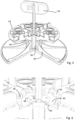
Fig. 2 shows an exploded perspective view of the system according to an embodiment of the invention; -
Fig. 3 shows the tile support and locking element of the system ofFig. 2 in detail, with the leaf spring placed in the tile support; -
Fig. 4 illustrates the insertion of the corner element in the tile support ofFig. 3 that has its locking element in the open position; -
Fig. 5 and 6 shows a partial cross-section of the system ofFig. 2 , with the locking element in its open position; -
Fig. 7 shows a partial cross-section of the system ofFig. 2 , with the locking element in its locking position; -
Fig. 8 shows a perspective bottom view of the system of Fig. 12 that illustrates the locking position of the locking element; and -
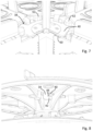
Fig. 9 and 10 show a perspective bottom view of the system ofFig. 2 to illustrate the arresting means, wherein for illustrative purposes the locking element is not shown inFig. 9 while it is shown inFig. 10 . -
Figure 1 shows thesystem 2 for forming atiled floor 4 on an outdoor subsurface, in this embodiment aroof 6. Thesystem 2 is shown in more detail infigure 2 . Thesystem 2 comprises atile support 8 and acorner element 10. Thecorner element 10 is designed for receiving a lower corner of atile 12. In this embodiment, thecorner elements 10 are bonded to thetiles 12 using an adhesive, such as adhesive double-sided tape 14. - The
tile support 8 is designed to receive thetiles 12, in this embodiment fourtiles 12, via therespective corner elements 10. Infig. 2 , only onecorner element 10 is shown for illustrative purposes. Generally, most tile supports 8 of atiled floor 4 will support the corners of fourtiles 12, each tile being provided with acorner element 10. Typically, only tile supports 8 positioned at the edges of thetiled floor 4 will carry less than fourtiles 12, e.g. two tiles (along the edge of the tiled floor) or a single tile (at a corner of the tiled floor). - Referring to
fig. 2 , thecorner element 10 comprises acorner plate 16 with anupper side 18 and alower side 20. Theupper side 18 is connectable to the lower corner of thetile 12 and thelower side 20 is dimensioned such as to be received by thetile support 8. Thetile support 8 comprises abody 22 having an upper receivingface 24 for receiving the fourcorner elements 10. Thetile support 8 further has alower face 26, which in this embodiment is the lower face of apedestal 28 that forms part of thebody 22. Thepedestal 28 is designed for positioning on an outdoor subsurface such as a roof or balcony. - The
pedestal 28 is placed on an optional slopedplate 30. In this embodiment, the slopedplate 30 has a slope of 2°. The slopedplate 30 is equipped on its upper surface with aridge 32 along its circumference for positioning thepedestal 28 atop the slopedplate 30 and within the confines of theridge 32. In this embodiment, the slopedplate 30 has a circular shape that matches the circular shape of the lower face of thepedestal 28. Optionally, at least two identical circle-shaped slopedplate 30 are provided. By rotating two circle-shapedslope plates 30 with respect to each other the slope angle can be set to a desired angle between 0° to 4°. If only a height adjustment is desired, thesloped plates 30 are placed at an angle of 180° with respect to each other to achieve a slope of 0° degrees. Similarly, using three circle-shapedsloped plates 30 enables adjusting a slope angle between 0° to 6°. - The
corner element 10 comprises a lockingpin 34. The lockingpin 34 extends vertically from thelower side 20 of thecorner element 10. In this embodiment, thecorner element 10 further comprises fourpositioning walls 36. - The
body 22 of thetile support 8 comprises apin receiving hole 38 for receiving the lockingpin 34. In the assembled state of the system, thelower side 20 of thecorner element 10 rests on the upper receivingface 24 of thetile support 8 and the lockingpin 34 extends in thepin receiving hole 38. - The
tile support 8 comprises a lockingelement 40 which is rotatably provided at thepin receiving hole 38. The lockingelement 40 is rotatable from an open position (fig. 4-6 ) to a locking position (fig. 7-10 ), as will be explained below in more detail. - In this embodiment, the locking
pin 34 has a restrictedprotrusion 42 with a length which is less than a length of the locking pin 34 (fig. 2 andfig. 8 ). The restrictedprotrusion 42 is provided at a lower end of the lockingpin 34, and comprises anupper face 44. The lockingelement 40 engages theupper face 44 of the restrictedprotrusion 42 for locking the lockingpin 34 in thepin receiving hole 38 in the locking position (fig. 8 and10 ). - In this embodiment, the
tile support 8 comprises a positioning ridge 46 (fig. 2 ) along an edge of the upper receivingface 24 of thetile support body 22 for positioning thecorner element 10 on thetile support 8 along thepositioning ridge 46. Thetile support 8 further comprises fourtile spacers 48 which extend vertically from the upper receivingface 24. One or more of thetile spacers 48 may be broken away from thetile support body 22 in order to provide a partly or fully freeupper receiving face 24, for instance to enable positioning thetile support 8 at an edge or corner of thetiled floor 4. Thetile support 8 and thecorner element 10 are dimensioned such that thecorner element 10 fits between a quarter part of thepositioning ridge 46 and two of thetile spacers 48. - The
rotatable locking element 40 comprises a plate-shaped element with a rotational symmetric shape withflanges 50 along its edge (fig. 2 and3 ). In this embodiment, the lockingelement 40 has fourflanges 50. The lockingelement 40 has a hexagonaloperative hole 52 for rotating the locking element from above using a key 54 with a matching shape (fig. 5 ), i.e. to move the lockingelement 40 from its open position to its locking position. - The
system 2 further comprises arresting means for holding the lockingelement 40 in its locking position. In this embodiment, the arresting means comprises aboss 56 formed on a lower side of thebody 22 of thetile support 8 facing an upper side of the lockingelement 40 and anopening 58 in the lockingelement 40 for receiving said boss 56 (fig. 9 and 10 ). Infigure 9 , the lockingelement 40 is omitted to more clearly illustrate theboss 56. The arresting means further comprises aleaf spring 60 arranged to press theboss 56 in theopening 58 when the lockingelement 40 is in its locking position (fig. 9 and 10 ). Particularly, theleaf spring 60 is positioned in arecess 61 in thebody 22 of thetile support 8, via the upper receivingface 24. The lockingelement 40 is positioned on top of the leaf spring 60 (fig. 3 and 4 ). Theleaf spring 60 is thus arranged to press the lockingelement 40 upwards against a lower surface of an edge of therecess 61. In particular, along the edge of therecess 61flanges 62 are formed that extend inwards, i.e. towards the centre of thebody 22, and provide an abutment surface for the lockingelement 40. As shown infig. 10 , in the locking position of the lockingelement 40, theflanges 50 of the lockingelement 40 are pressed against theflanges 62 around therecess 61.Fig. 10 further shows that thebosses 56 are formed on the lower surface of theflanges 62. In this embodiment, eachflange 50 of the lockingelement 40 is provided with at least oneopening 58 and correspondingly at least oneboss 56 is formed on thebody 22 of thetile support 8 for each flange. Using multiple pairs of bosses and openings has the advantage of solidly keeping the lockingelement 40 in its locked position. In this embodiment, the lockingelement 40 comprises twoopenings 58 in each of itsflanges 50 which are positioned symmetrically on therespective flange 50. This ensures that the lockingelement 40 is symmetric, i.e. is the same irrespective of which side faces up. This avoids accidentally placing the wrong side up during assembly of thetile support 8. - As shown in
figure 5 , thebody 22 of thetile support 8 comprises atop part 64, that includes the receivingface 24, and apedestal 28 that forms a lower part of thebody 22. Thebody 22 further comprises abolt 66 that connects thetop part 64 and thepedestal 28, using a threaded connection. In the embodiment, thebolt 66 has an external thread and thetop part 64 andpedestal 28 have an opening with an internal thread. Tile supports 8 of different heights are obtained by usingbolts 66 of a different lengths. This has the advantage that only a single type oftop part 64 and a single type ofpedestal 28 needs to be manufactured, while still being able to provide tile supports 8 of different heights. - The
tile support body 22 assembled from thepedestal 28, thetop part 64 and thebolt 66, is then assembled into afull tile support 8 by insertingspring 60 intorecess 61 and subsequently placing lockingelement 40 on top of thespring 60. When creating atiled floor 4 above an outdoor subsurface, such as a roof, balcony, or an outdoor corridor, thetile support 8 can be assembled on-site, but preferably thetile support 8 is pre-assembled to decrease the time of on-site construction. Atiled floor 4 is then assembled by means of the following steps.Multiple tiles 12,corner elements 10 and tile supports 8 (preferably pre-assembled) are provided. Thecorner elements 10 are bonded to at least some of the corners of themultiple tiles 12, e.g. with an adhesive double-sided tape 14. The tile supports 8 are positioned on theroof 6 at regular intervals, to form a grid with dimensions corresponding to the dimensions of thetiles 12. - Each of the
tiles 12 is placed with a vertical movement on four tile supports 8, such that the lockingpin 34 enters thepin receiving hole 38 until thecorner elements 10 rest on therespective tile support 8. The restrictedprotrusion 42 of the lockingpin 34 passes the lockingelement 40, as the restrictedprotrusion 34 can pass through the space defined between twoflanges 50 of the lockingelement 40. In this position, theupper face 44 of the restrictedprotrusion 34 is positioned at a lower position than the lower surface of the lockingelement 40. As a next step, the key 54 is inserted into theoperative hole 52 of the lockingelement 40, and the lockingelement 40 is rotated from its open position, as shown infig. 4 - 6 to the locking position, as shown infig. 7, 8 and10 . In this locking position, theupper face 44 of the restrictedprotrusion 42 is positioned below the lower surface of the lockingelement 40 so that the lockingpin 34 is locked relative to thepin receiving hole 38. When the lockingelement 40 is rotated to the locking position, theboss 56 formed on thebody 22 of thetile support 8 enters theopening 58 of the locking element 40 (fig. 10 ). Thespring 60 exerts an upward spring force upon the lockingelement 40 that keep theboss 56 in theopening 58 by pressing the lockingelement 40 against the lower surface of theflanges 62. - If it is desired to disassemble a tiled floor, the locking
element 40 can be pushed against the spring force ofspring 60 to moveboss 56 out of theopening 58, after which thelocking element 40 can be rotated in the opposite direction. In the illustrated embodiment, the lockingelement 40 is provided with anoptional sticker 68 which has printed on its top side anarrow 70 indicating the direction for moving the lockingelement 40 to its open position. Alternatively or additionally, the direction for moving the lockingelement 40 to its locking position is printed on thesticker 68. - Several variants are possible within the scope of the attached claims. All features of the system are suitable and intended for the tiled floor, as well as for the method. The features of the above described preferred embodiment may be replaced by any other feature within the scope of the attached claims, such as the features described in the following paragraphs and under the general description.
- In the embodiment of the figures, the body of the tile support comprises a top part and a lower part that are movable with respect to each other in the vertical direction, to allow height adjustment of the tile support. Alternatively, the body of the tile support can be formed as an integral component.
- In an embodiment, the arresting means comprise a first part formed on the body of the tile support and a second part formed on the locking element. The first and second part are arranged to align with each other in the locking position for coupling the first and second part with each other. For example, the first and second part comprise an opening and a boss as described above, wherein the boss and opening align when the locking element is in its locking position. Alternatively, the arresting means comprises a hole in the locking element and a hole in the body of the tile support, wherein these holes arranged to align when the locking element is in its locking position, and the arresting means further comprises a pin, bolt or screw for inserting into the holes to thereby lock movement of the locking element with respect to the body of the tile support.
- In the embodiment of the figures, the boss is formed on the body of the tile support and the opening is formed in the locking element. Alternatively, a boss is formed on the locking element and the body of the tile support comprises an opening for receiving said boss.
- In the figures, the spring is arranged to press the locking element upwards against a lower surface of the tile support body. In an alternate embodiment, a spring is arranged to press the locking element downwards against an upper surface of the body of the tile support. In this embodiment, said upper surface of the tile support body is provided with the boss or opening for engaging with the opening or boss of the locking element.
- In the illustrated embodiments, the opening for receiving the boss and the boss have a circular cross-section. However, the boss and opening may have any other suitable shape, such as square, rectangular or elliptic.
- Likewise, the locking pin and/or the pin receiving hole may have different shapes and cross-sections than those shown in the example of the figures. Whereas the locking pin in the figures has a restricted protrusion to form a hook-shaped locking pin, the locking pin may alternatively consist of a vertically extending part only. In such embodiment, the locking element may include a recess to receive the locking pin in a formfitting manner, i.e. the locking element and the locking pin engage in a formfitting manner. Alternatively or additionally, the locking pin has a recess for receiving the locking element in a formfitting manner. These formfitting connections may optionally be combined with a locking pin having a restricted protrusion as disclosed above. In other words, in any of the embodiments disclosed herein, the arresting means may comprise formfitting arresting means.
- In an embodiment, the operative hole of the locking element has a rectangular shape, and the matching key is a flat screwdriver. In an alternative embodiment, the operative hole has a star shape, and the matching key is a matching screwdriver, e.g. a Phillips, Pozidrive, or Torx type screwdriver.
- The shape of the tiles may be square, rectangular, triangular, hexagonal, or octagonal. The tile supports of a system for such tiles will be suitable to receive a corresponding number of tile corners. The material of the tiles may be concrete, natural stone, or a composite material, instead of the preferred ceramics. The system is suitable for any outdoor situation.
- In an embodiment, the system is used without a pedestal. In an embodiment, the corner element is provided without a positioning wall. In an embodiment, the tile support is provided without a tile spacer and/or without a positioning ridge.
- The above embodiments describe connecting a tile to a corner element by means of double sided adhesive tape, but the invention is not limited to this manner of connecting the tile. Alternatively or additionally, the tile is bonded to the corner element with glue. In an alternative embodiment, a tile is formed from a fluid material, such as concrete, and the corner element is provided with protrusions in its upper side which are put inside the soft concrete and after hardening forms a bond between the tile and the corner element. In a further alternative embodiment, the tiles and corner elements are connected by providing the tiles with protrusions that engage with corresponding holes provided in the corner element in a formfitting manner. Equivalently, the tiles may be provided with holes that engage with protrusions provided to the corner elements.
- In an embodiment, the locking element is slidable sideways, instead of rotatable.
Claims (15)
- System (2) for forming a tiled floor (4) on an outdoor subsurface (6), such as a roof, balcony, or an outdoor corridor, comprising a tile support (8) for supporting at least two tiles (12) and a corner element (10) for receiving a lower corner of one of the tiles (12), whereinthe corner element (10) comprises a corner plate (16) with an upper side (18) and a lower side (20), the upper side (18) being connectable to the lower corner of the tile (12) and the lower side (20) being dimensioned such as to be received by the tile support (8),the tile support (8) comprises a body (22), the body (22) having an upper receiving face (24) for receiving at least two such corner elements (10) and a lower face (26) which is placeable on the outdoor subsurface (6) or on a pedestal positioned on the outdoor subsurface (6),the corner element (10) comprises a locking pin (34) which extends vertically from the lower side (20),the body (22) of the tile support (8) comprises a pin receiving hole (38) for receiving the locking pin (34), wherein in an assembled state of the system, the lower side (20) of the corner element (10) rests on the upper receiving face (24) of the body (22) of the tile support (8) and the locking pin (34) extends in the pin receiving hole (38), andthe tile support (8) further comprises a locking element (40) provided at the pin receiving hole (34), wherein the locking element (40) is movable from an open position, which enables the locking pin (34) to enter or leave the pin receiving hole (38), to a locking position in which the locking element (40) engages the locking pin (34) to prevent the locking pin (34) to move out of the pin receiving hole (38), characterized in thatthe system (2) comprises arresting means (56, 58, 60) which engage with the body (22) of the tile support (8) and with the locking element (40) for holding the locking element (40) in its locking position.
- System (2) according to claim 1, wherein the arresting means comprise:a boss (56) formed on one of the body (22) of the tile support (8) and the locking element (40); andan opening (58) for receiving said boss (56) when the locking element (40) is in its locking position, formed in the other of the locking element (40) and the body (22) of the tile support (8), respectively.
- System (2) according to claim 1 or 2, wherein the arresting means further comprise a spring (60) arranged to hold the locking element (40) in its locking position.
- System (2) according to the combination of claim 2 and 3, wherein the spring (60) is arranged to press the boss (56) in the opening (58) when the locking element (40) is in its locking position.
- System (2) according to claim 3 or 4, wherein the locking element (40) is movable against a force exerted by the spring (60) for disengaging the arresting means.
- System (2) according to any one or more of the preceding claims, wherein the locking element (40) is rotatable from the open position to the locking position.
- System (2) according to any one or more of claims 3-6, wherein the locking element (40) is provided in a recess (61) in the upper receiving face (24) of the body (22) of the tile support (8), and the spring (60) is arranged to press the locking element (40) upwards such that, in the locking position, the spring (60) presses the locking element (40) against a lower surface of an edge of the recess (61).
- System (2) according to claim 7, wherein the locking element (40) is a plate-shaped element having a rotational symmetric shape with flanges (50) formed along its edge, and the recess (61) has a shape that matches the shape of the locking element (40) such that, in the locking position, the spring (60) presses the flanges (50) of the locking element (40) against the lower surface of the edge of the recess (61).
- System (2) according to any one or more of the claims 1-8, wherein the locking element (40) comprises a hole (52), and the system (2) further comprises a tool (54) with a shape that matches a shape of the hole (52) in the locking element (40) for using the tool (54) to move the locking element (40) from its open position to its locking position, and/or the locking pin (34) comprises a restricted protrusion (42) with a length which is less than a length of the locking pin (34), the restricted protrusion (42) is provided at a lower end of the locking pin (34), and the locking element (40), in its locking position, engages an upper face (44) of the restricted protrusion (34) to prevent the locking pin (34) to move out of the pin receiving hole (38).
- System (2) according to any one or more of the preceding claims, wherein the body (22) of the tile support (8) comprises a pedestal (28) for positioning on the outdoor subsurface (6), the system in particular further comprising at least one sloped plate (30) for compensating a slope of the outdoor surface (6), the sloped plate comprising on its upper surface a ridge (32) for positioning the pedestal (28) atop the sloped plate (30).
- System (2) according to any one or more of the preceding claims, wherein the body (22) of the tile support (8) comprises a positioning ridge (46) along an edge of the upper receiving face (24) for positioning the corner element (10) on the tile support (8) along the positioning ridge (46).
- System (2) according to any one or more of the preceding claims, wherein the body (22) of the tile support (8) comprises at least one tile spacer (48) which extends from the upper receiving face (24).
- Tiled floor (4), comprising multiple combinations of a tile (12) having multiple lower corners and at least one corner element (10), comprising multiple tile supports (8) provided at at least a plurality of the multiple corners of the tiles (12), an arresting means (56, 58, 60), wherein the at least one corner element (1), the multiple tile supports (8), and the arresting means are defined in any one or more of the preceding claims, andthe upper side (18) of each corner element (10) is fixedly connected to one of the lower corners of the corresponding tile (12),the upper receiving face (24) of the body (22) of each tile support receives at least two such corner elements (10), wherein the lower side (20) of each corner element (10) rests on the upper receiving face (24) of the corresponding tile support (8), the lower face (26) of the body (22) of each tile support (8) is placed on the outdoor subsurface (6) or on a pedestal positioned on the outdoor subsurface (6), characterized, in thatthe tiled floor (4) comprises arresting means (56, 58, 60) which engage with the body (22) of the tile support (8) and with the locking element (40) for holding the locking element (40) in its locking position.
- Tile support (8) for a system (2) for forming a tiled floor (4) on an outdoor subsurface (6) according to any one or more of the claims 1-12, comprising:a body (22) having an upper receiving face (24) for receiving at least two corner elements (10) for receiving a lower corner of one of the tiles (12), the body (22) further having a lower face (26) which is placeable on an outdoor subsurface (6) or on a pedestal positioned on the outdoor subsurface (6), the body (22) comprising a pin receiving hole (38) for receiving a locking pin (34) which extends vertically from a lower side (20) of one of the corner elements (10); anda locking element (40) provided at the pin receiving hole (38), wherein the locking element (40) is movable from an open position, which enables the locking pin (34) to enter or leave the pin receiving hole (38), to a locking position in which the locking element (40) engages the locking pin (34) to prevent the locking pin (34) to move out of the pin receiving hole (38),characterized, in that
the tile support (8) further comprises arresting means (56, 58, 60) which engage with the body (22) of the tile support (8) and the locking element (40) for holding the locking element (40) in its locking position. - Method for assembling a tiled floor (4) above an outdoor subsurface (6), such as a roof, balcony, or an outdoor corridor, comprising the steps of:- providing multiple tiles (12) with corner elements (10) under at least one of the respective tile corners, wherein the corner elements (10) each comprises a locking pin (34) which extends vertically from the lower side (20) of the corner element (10),- providing tile supports (8), wherein the tile supports (8) each comprise a body (22) having an upper receiving face (24) for receiving at least two such corner elements (10), a lower face (26) and at least one pin receiving hole (38) for receiving the locking pin (34),- positioning the tile supports (8) in a grid-like configuration corresponding to the dimensions of the tiles (12), either directly on the outdoor subsurface (6) or on a pedestal placed on the outdoor subsurface (6),- placing each of the multiple tiles (12) with a vertical movement on the tile supports (8), such that the locking pins (34) enter the respective pin receiving holes (38) until the corner element (10) rests on the tile support (8),- moving a locking element (40) of each of the tile supports (8) to a locking position, wherein the locking element (40) engages the respective locking pin (34) in order to lock the locking pins (34) relative to the pin receiving holes (38), characterised in thatthe step of moving the locking element (40) comprises having arresting means (56, 58, 60) engage with the body (22) of the tile support (8) and with the locking element (40) to hold the locking element (40) in its locking position.
Applications Claiming Priority (1)
| Application Number | Priority Date | Filing Date | Title |
|---|---|---|---|
| NL2035445A NL2035445B1 (en) | 2023-07-21 | 2023-07-21 | System for forming a tiled floor on an outdoor subsurface, tiled floor, tile support and method for assembling a tiled floor |
Publications (1)
| Publication Number | Publication Date |
|---|---|
| EP4495353A1 true EP4495353A1 (en) | 2025-01-22 |
Family
ID=88068759
Family Applications (1)
| Application Number | Title | Priority Date | Filing Date |
|---|---|---|---|
| EP24189796.6A Pending EP4495353A1 (en) | 2023-07-21 | 2024-07-19 | System for forming a tiled floor on an outdoor subsurface, tiled floor, tile support and method for assembling a tiled floor |
Country Status (2)
| Country | Link |
|---|---|
| EP (1) | EP4495353A1 (en) |
| NL (1) | NL2035445B1 (en) |
Citations (2)
| Publication number | Priority date | Publication date | Assignee | Title |
|---|---|---|---|---|
| EP0483417A1 (en) * | 1990-10-25 | 1992-05-06 | Naka Corporation | Device for fixing floor panels |
| EP3507420A1 (en) | 2016-08-31 | 2019-07-10 | Zoontjens Beton B.V. | System and method for forming a tiled floor |
-
2023
- 2023-07-21 NL NL2035445A patent/NL2035445B1/en active
-
2024
- 2024-07-19 EP EP24189796.6A patent/EP4495353A1/en active Pending
Patent Citations (2)
| Publication number | Priority date | Publication date | Assignee | Title |
|---|---|---|---|---|
| EP0483417A1 (en) * | 1990-10-25 | 1992-05-06 | Naka Corporation | Device for fixing floor panels |
| EP3507420A1 (en) | 2016-08-31 | 2019-07-10 | Zoontjens Beton B.V. | System and method for forming a tiled floor |
Also Published As
| Publication number | Publication date |
|---|---|
| NL2035445B1 (en) | 2025-02-04 |
Similar Documents
| Publication | Publication Date | Title |
|---|---|---|
| CA2409312C (en) | Ballast block deck system and pedestal assembly therefor | |
| CA2521094C (en) | Structurally integrated accessible floor system | |
| US9038324B2 (en) | Field paver connector and restraining system | |
| US8490342B2 (en) | Batten/joist support | |
| US8695288B2 (en) | Structural systems for restraining elevated surface tiles | |
| US8850770B2 (en) | Structurally integrated accessible floor system | |
| EP3507420B1 (en) | System and method for forming a tiled floor | |
| WO2015054750A1 (en) | Fasteners for pedestal supported tiles or decking | |
| US9273464B2 (en) | Structurally integrated accessible floor system | |
| US10801215B2 (en) | Flooring support system | |
| EP2430252B1 (en) | Structurally integrated accessible floor system | |
| NL2035445B1 (en) | System for forming a tiled floor on an outdoor subsurface, tiled floor, tile support and method for assembling a tiled floor | |
| GB2363401A (en) | Stackable building component | |
| US10794067B2 (en) | Flooring support system | |
| KR102716729B1 (en) | Raised floor | |
| KR200280824Y1 (en) | Floor construction work device | |
| GB2417503A (en) | Floor supports, e.g. to improve soundproofing | |
| JP4684491B2 (en) | Bunch of floor panels | |
| WO2024197346A1 (en) | Concealed paver retainer | |
| CN115538617A (en) | Building connection system and modular building with same | |
| JPH0122826Y2 (en) | ||
| IE902937A1 (en) | Raised flooring system |
Legal Events
| Date | Code | Title | Description |
|---|---|---|---|
| PUAI | Public reference made under article 153(3) epc to a published international application that has entered the european phase |
Free format text: ORIGINAL CODE: 0009012 |
|
| STAA | Information on the status of an ep patent application or granted ep patent |
Free format text: STATUS: THE APPLICATION HAS BEEN PUBLISHED |
|
| AK | Designated contracting states |
Kind code of ref document: A1 Designated state(s): AL AT BE BG CH CY CZ DE DK EE ES FI FR GB GR HR HU IE IS IT LI LT LU LV MC ME MK MT NL NO PL PT RO RS SE SI SK SM TR |
|
| STAA | Information on the status of an ep patent application or granted ep patent |
Free format text: STATUS: REQUEST FOR EXAMINATION WAS MADE |
|
| 17P | Request for examination filed |
Effective date: 20250709 |