EP4495337A1 - Method and control system for actuating a return function of an articulated arm of a work or agricultural vehicle - Google Patents
Method and control system for actuating a return function of an articulated arm of a work or agricultural vehicle Download PDFInfo
- Publication number
- EP4495337A1 EP4495337A1 EP24179298.5A EP24179298A EP4495337A1 EP 4495337 A1 EP4495337 A1 EP 4495337A1 EP 24179298 A EP24179298 A EP 24179298A EP 4495337 A1 EP4495337 A1 EP 4495337A1
- Authority
- EP
- European Patent Office
- Prior art keywords
- prime mover
- hydraulic
- vehicle
- rotation
- return function
- Prior art date
- Legal status (The legal status is an assumption and is not a legal conclusion. Google has not performed a legal analysis and makes no representation as to the accuracy of the status listed.)
- Pending
Links
Images
Classifications
-
- E—FIXED CONSTRUCTIONS
- E02—HYDRAULIC ENGINEERING; FOUNDATIONS; SOIL SHIFTING
- E02F—DREDGING; SOIL-SHIFTING
- E02F9/00—Component parts of dredgers or soil-shifting machines, not restricted to one of the kinds covered by groups E02F3/00 - E02F7/00
- E02F9/20—Drives; Control devices
- E02F9/2025—Particular purposes of control systems not otherwise provided for
- E02F9/2041—Automatic repositioning of implements, i.e. memorising determined positions of the implement
-
- E—FIXED CONSTRUCTIONS
- E02—HYDRAULIC ENGINEERING; FOUNDATIONS; SOIL SHIFTING
- E02F—DREDGING; SOIL-SHIFTING
- E02F9/00—Component parts of dredgers or soil-shifting machines, not restricted to one of the kinds covered by groups E02F3/00 - E02F7/00
- E02F9/20—Drives; Control devices
- E02F9/22—Hydraulic or pneumatic drives
- E02F9/2221—Control of flow rate; Load sensing arrangements
- E02F9/2232—Control of flow rate; Load sensing arrangements using one or more variable displacement pumps
- E02F9/2235—Control of flow rate; Load sensing arrangements using one or more variable displacement pumps including an electronic controller
-
- E—FIXED CONSTRUCTIONS
- E02—HYDRAULIC ENGINEERING; FOUNDATIONS; SOIL SHIFTING
- E02F—DREDGING; SOIL-SHIFTING
- E02F9/00—Component parts of dredgers or soil-shifting machines, not restricted to one of the kinds covered by groups E02F3/00 - E02F7/00
- E02F9/20—Drives; Control devices
- E02F9/22—Hydraulic or pneumatic drives
- E02F9/2246—Control of prime movers, e.g. depending on the hydraulic load of work tools
-
- E—FIXED CONSTRUCTIONS
- E02—HYDRAULIC ENGINEERING; FOUNDATIONS; SOIL SHIFTING
- E02F—DREDGING; SOIL-SHIFTING
- E02F9/00—Component parts of dredgers or soil-shifting machines, not restricted to one of the kinds covered by groups E02F3/00 - E02F7/00
- E02F9/20—Drives; Control devices
- E02F9/22—Hydraulic or pneumatic drives
- E02F9/2253—Controlling the travelling speed of vehicles, e.g. adjusting travelling speed according to implement loads, control of hydrostatic transmission
-
- E—FIXED CONSTRUCTIONS
- E02—HYDRAULIC ENGINEERING; FOUNDATIONS; SOIL SHIFTING
- E02F—DREDGING; SOIL-SHIFTING
- E02F9/00—Component parts of dredgers or soil-shifting machines, not restricted to one of the kinds covered by groups E02F3/00 - E02F7/00
- E02F9/20—Drives; Control devices
- E02F9/22—Hydraulic or pneumatic drives
- E02F9/2278—Hydraulic circuits
- E02F9/2292—Systems with two or more pumps
-
- E—FIXED CONSTRUCTIONS
- E02—HYDRAULIC ENGINEERING; FOUNDATIONS; SOIL SHIFTING
- E02F—DREDGING; SOIL-SHIFTING
- E02F9/00—Component parts of dredgers or soil-shifting machines, not restricted to one of the kinds covered by groups E02F3/00 - E02F7/00
- E02F9/20—Drives; Control devices
- E02F9/22—Hydraulic or pneumatic drives
- E02F9/2278—Hydraulic circuits
- E02F9/2296—Systems with a variable displacement pump
-
- E—FIXED CONSTRUCTIONS
- E02—HYDRAULIC ENGINEERING; FOUNDATIONS; SOIL SHIFTING
- E02F—DREDGING; SOIL-SHIFTING
- E02F9/00—Component parts of dredgers or soil-shifting machines, not restricted to one of the kinds covered by groups E02F3/00 - E02F7/00
- E02F9/26—Indicating devices
- E02F9/264—Sensors and their calibration for indicating the position of the work tool
- E02F9/265—Sensors and their calibration for indicating the position of the work tool with follow-up actions (e.g. control signals sent to actuate the work tool)
-
- F—MECHANICAL ENGINEERING; LIGHTING; HEATING; WEAPONS; BLASTING
- F16—ENGINEERING ELEMENTS AND UNITS; GENERAL MEASURES FOR PRODUCING AND MAINTAINING EFFECTIVE FUNCTIONING OF MACHINES OR INSTALLATIONS; THERMAL INSULATION IN GENERAL
- F16H—GEARING
- F16H61/00—Control functions within control units of change-speed- or reversing-gearings for conveying rotary motion ; Control of exclusively fluid gearing, friction gearing, gearings with endless flexible members or other particular types of gearing
- F16H61/38—Control of exclusively fluid gearing
- F16H61/40—Control of exclusively fluid gearing hydrostatic
- F16H61/46—Automatic regulation in accordance with output requirements
- F16H61/47—Automatic regulation in accordance with output requirements for achieving a target output speed
-
- B—PERFORMING OPERATIONS; TRANSPORTING
- B60—VEHICLES IN GENERAL
- B60Y—INDEXING SCHEME RELATING TO ASPECTS CROSS-CUTTING VEHICLE TECHNOLOGY
- B60Y2200/00—Type of vehicle
- B60Y2200/40—Special vehicles
- B60Y2200/41—Construction vehicles, e.g. graders, excavators
- B60Y2200/415—Wheel loaders
-
- E—FIXED CONSTRUCTIONS
- E02—HYDRAULIC ENGINEERING; FOUNDATIONS; SOIL SHIFTING
- E02F—DREDGING; SOIL-SHIFTING
- E02F9/00—Component parts of dredgers or soil-shifting machines, not restricted to one of the kinds covered by groups E02F3/00 - E02F7/00
- E02F9/20—Drives; Control devices
- E02F9/22—Hydraulic or pneumatic drives
- E02F9/2278—Hydraulic circuits
- E02F9/2282—Systems using center bypass type changeover valves
-
- F—MECHANICAL ENGINEERING; LIGHTING; HEATING; WEAPONS; BLASTING
- F16—ENGINEERING ELEMENTS AND UNITS; GENERAL MEASURES FOR PRODUCING AND MAINTAINING EFFECTIVE FUNCTIONING OF MACHINES OR INSTALLATIONS; THERMAL INSULATION IN GENERAL
- F16H—GEARING
- F16H63/00—Control outputs from the control unit to change-speed- or reversing-gearings for conveying rotary motion or to other devices than the final output mechanism
- F16H63/40—Control outputs from the control unit to change-speed- or reversing-gearings for conveying rotary motion or to other devices than the final output mechanism comprising signals other than signals for actuating the final output mechanisms
- F16H63/50—Signals to an engine or motor
Definitions
- the present invention relates to the field of methods and systems for controlling the actuation of hydraulic members of work or agricultural vehicles.
- the hydraulic circuit is powered by a hydraulic pump driven in rotation by a prime mover, most often an internal combustion engine.
- hydraulic work unit it is meant one of those components such as arms, buckets, etc.. distinct and separate from those inherent in the propulsion of the work vehicle, such as for example transmissions, braking systems, etc. Below, for convenience, reference is made to a “hydraulic unit” meaning a “work hydraulic member”.
- the lifting and lowering of the arm is achieved by at least one double-acting linear hydraulic actuator. It comprises a pair of opposing chambers, which alternately fill and empty to effect the raising or lowering of the boom.
- the valve for controlling a hydraulic actuator is usually controlled by the operator using a joystick located in the cockpit of the vehicle.
- the electric signal generated by the joystick is acquired by a processing unit, which processes it to control the directional control valve arranged to control the corresponding hydraulic actuator.
- the directional control valve is evidently of the electro-hydraulic type.
- the hydraulic circuit that feeds the hydraulic actuator through the directional valve is fed, in turn, by a hydraulic pump driven in rotation by the prime mover.
- the prime mover is generally of the internal combustion type, although the electrification of vehicles is expected in the coming years and therefore the replacement of the internal combustion engine with one or more electric motors.
- the prime mover is an internal combustion engine
- all the hydraulic pumps on board of the vehicle are driven in rotation by the prime mover, therefore, it is connected to the hydraulic feed pump of the hydraulic circuit serving the hydraulic organs and the transmission for vehicle propulsion.
- the vehicle transmission is generally composed of a hydrostat, which comprises a variable displacement hydraulic pump, which supplies a hydraulic motor connected directly or indirectly to a vehicle wheel with hydraulic oil.
- the rotational speed of the prime mover is controllable with an accelerator pedal.
- the accelerator pedal is used to control the movement of the vehicle, therefore the rotation speed of the hydraulic pump depends on the position of the accelerator pedal.
- the actuation speed of a hydraulic member is a function of the vehicle speed.
- the object of the present invention is to increase the productivity of a work or agricultural vehicle equipped with an articulated arm comprising a bucket or a fork.
- the main idea of the present invention is that of realizing an acceleration procedure of a hydraulic actuator based on the increase of the rotation speed of the prime mover and the contextual adaptation of the hydrostat so as to maintain the speed of the vehicle independent of the rotation speed of the prime mover, in response to the activation of one of the following functions:
- the first function Return to Dig, automatically places the bucket or fork in a position suitable for loading material or a pallet.
- the Return to Travel function is similar to the Return to Dig function, with the difference that it automatically lowers the boom in a position that does not obstruct an adequate view of the surrounding environment while the vehicle is moving. It is typically recalled as the vehicle moves along a route.
- the Return to Height function is still similar to the previous ones and has the purpose of bringing the arm to a predetermined height from the ground, for example to be unloaded inside the loading compartment of a transport vehicle, or on a warehouse shelf.
- the present invention proposes a control method of the propulsion system of an agricultural or work vehicle VEH, for example according to the scheme of Figs. 1 and 3 of the prior art.
- the transmission HY comprises an electrically controllable variable displacement hydraulic pump HP and an electrically controllable hydraulic motor HM with fixed or variable displacement.
- the shaft of the hydraulic motor is operatively connected to a driving axle RA and/or FA, preferably, but not necessarily, through a discrete ratio gearbox GB.
- the driving axle can be equipped with a differential DF, which distributes the drive torque to the axle shafts, which drive the wheels W in rotation.
- the hydraulic pump and the hydraulic motor are hydraulically interconnected by a high pressure line F and a low pressure line R, also called delivery line and return line.
- a processing unit ECU is configured to control the operation of the prime mover E, generally an internal combustion engine and more preferably diesel cycled.
- Another processing unit UCM is arranged to control the operation of human/machine interfaces, such as the throttle lever AP, the brake lever BP and the selector position HT to select the park, forward and reverse configurations.
- the processing unit UCM receives as input some parameters including the rotation speed ES of the prime mover E and the vehicle speed VS as well as the signals generated by the man/machine interfaces and manages, among other things, the hydrostat HY and work members such as, for example, an articulated arm AB and the like.
- the hydraulic work members are actuated by means of hydraulic actuators, fed by a dedicated hydraulic circuit, fed by a hydraulic pump driven in rotation by the prime mover E, as shown in Fig. 2 .
- Fig. 2 shows an example of an electrohydraulic circuit HC.
- the fixed geometry hydraulic pump P feeds the hydraulic circuit HC drawing hydraulic oil from the collection tank T.
- the pump P is driven in rotation by the prime mover E.
- the rotation speed of the prime mover is automatically increased to allow the pump P to generate a greater flow of hydraulic oil and, at the same time, the hydrostat is adjusted so as to keep the vehicle speed unchanged.
- the Floating function is similar to one of the return functions limited to the first stage.
- At least the hydraulic pump HP has a variable displacement, this means that to keep the flow of oil generated by the hydraulic pump HP constant, its displacement is proportionally reduced, following the same law of increase of the rotation speed of the prime mover.
- Hydrostats are known in which not only the displacement of the hydraulic pump but also of the hydraulic motor can be controlled. In this case, it is possible to compensate the increase and then the reduction of the rotation speed of the prime mover by acting on the control of the displacement of the hydraulic pump HP - with reduction of the relative displacement - and/or of the hydraulic motor HM - with increase of the relative displacement.
- Sensors S1 and S2 can also be associated with boom and bucket/fork angle.
- the execution of the method object of the present invention is caused by the activation of any of the aforementioned functions, schematized in Fig. 2 with the buttons "RTD SWITCH” and/or “RTH SWITCH” and/or “RTT SWITCH” and/or “FLOATING SWITCH”.
- buttons are operatively connected with the processing unit UCM described above, as well as the joystick, which allows control of the articulated arm, the accelerator pedal AP and other parameters such as the vehicle speed VS and the rotation speed of the prime mover EX.
- the method object of the present invention provides for the execution of the following steps in succession:
- the method described here implies that the rotational speed of the prime mover is not under the control of the accelerator pedal as long as the return operation is in progress.
- the rotational speed of the prime mover returns under the control of the accelerator pedal.
- Fig. 4 shows further dashed blocks, indicating that they are optional.
- Step 1 the request for the return of the articulated arm to a prearranged position, for example of DIG, is monitored.
- steps 1 - 3 are performed in succession and the end of the return procedure is monitored, verifying step 4.
- step 5 is performed which involves bringing the rotation speed of the prime mover back under the control of the accelerator pedal.
- the present invention can advantageously be implemented through a computer program comprising coding means for carrying out one or more steps of the method, when this program is executed on a computer. Therefore, it is understood that the scope of protection extends to said computer program and also to computer-readable means comprising a recorded message, said computer-readable means comprising program coding means for carrying out one or more steps of the method, when said program is run on a computer. Variants of the non-limiting example described are possible, without however departing from the scope of protection of the present invention, including all equivalent embodiments for a person skilled in the art, to the contents of the claims.
Landscapes
- Engineering & Computer Science (AREA)
- General Engineering & Computer Science (AREA)
- Mining & Mineral Resources (AREA)
- Civil Engineering (AREA)
- Structural Engineering (AREA)
- Mechanical Engineering (AREA)
- Physics & Mathematics (AREA)
- Fluid Mechanics (AREA)
- Control Of Fluid Gearings (AREA)
Abstract
Description
- The present invention relates to the field of methods and systems for controlling the actuation of hydraulic members of work or agricultural vehicles.
- In the context of work and agricultural vehicles, the activation of the implements, such as arms and related tools, is achieved by means of a hydraulic circuit.
- The hydraulic circuit is powered by a hydraulic pump driven in rotation by a prime mover, most often an internal combustion engine.
- With "hydraulic work unit" it is meant one of those components such as arms, buckets, etc.. distinct and separate from those inherent in the propulsion of the work vehicle, such as for example transmissions, braking systems, etc. Below, for convenience, reference is made to a "hydraulic unit" meaning a "work hydraulic member".
- In work machines, the best known and most implemented members are the arms equipped with buckets or forks or other devices.
- The lifting and lowering of the arm is achieved by at least one double-acting linear hydraulic actuator. It comprises a pair of opposing chambers, which alternately fill and empty to effect the raising or lowering of the boom.
- The valve for controlling a hydraulic actuator is usually controlled by the operator using a joystick located in the cockpit of the vehicle.
- The electric signal generated by the joystick is acquired by a processing unit, which processes it to control the directional control valve arranged to control the corresponding hydraulic actuator. The directional control valve is evidently of the electro-hydraulic type.
- The hydraulic circuit that feeds the hydraulic actuator through the directional valve is fed, in turn, by a hydraulic pump driven in rotation by the prime mover. The prime mover is generally of the internal combustion type, although the electrification of vehicles is expected in the coming years and therefore the replacement of the internal combustion engine with one or more electric motors.
- When the prime mover is an internal combustion engine, all the hydraulic pumps on board of the vehicle are driven in rotation by the prime mover, therefore, it is connected to the hydraulic feed pump of the hydraulic circuit serving the hydraulic organs and the transmission for vehicle propulsion.
- The vehicle transmission is generally composed of a hydrostat, which comprises a variable displacement hydraulic pump, which supplies a hydraulic motor connected directly or indirectly to a vehicle wheel with hydraulic oil.
- Generally, the rotational speed of the prime mover is controllable with an accelerator pedal.
- When the agricultural or work vehicle is engaged in successive loading, moving and unloading operations, the accelerator pedal is used to control the movement of the vehicle, therefore the rotation speed of the hydraulic pump depends on the position of the accelerator pedal.
- Therefore, the actuation speed of a hydraulic member is a function of the vehicle speed.
- Unless specifically excluded in the detailed description that follows, what is described in this chapter is to be considered as an integral part of the detailed description.
- The object of the present invention is to increase the productivity of a work or agricultural vehicle equipped with an articulated arm comprising a bucket or a fork.
- The main idea of the present invention is that of realizing an acceleration procedure of a hydraulic actuator based on the increase of the rotation speed of the prime mover and the contextual adaptation of the hydrostat so as to maintain the speed of the vehicle independent of the rotation speed of the prime mover, in response to the activation of one of the following functions:
- Return to DIG
- Return to Travel
- Return to height
- Floating.
- The aforesaid functions are known to those skilled in the art and have in common the fact that they automatically reposition a tool in a predetermined position starting from any remote position.
- The first function, Return to Dig, automatically places the bucket or fork in a position suitable for loading material or a pallet.
-
US20020073833A1 describes the Return to Dig function. - The Return to Travel function is similar to the Return to Dig function, with the difference that it automatically lowers the boom in a position that does not obstruct an adequate view of the surrounding environment while the vehicle is moving. It is typically recalled as the vehicle moves along a route.
- The Return to Height function is still similar to the previous ones and has the purpose of bringing the arm to a predetermined height from the ground, for example to be unloaded inside the loading compartment of a transport vehicle, or on a warehouse shelf.
- The dependent claims describe preferred variants of the invention, forming an integral part of the present description.
- Further objects and advantages of the present invention will become clear from the detailed description that follows of an embodiment of the same (and of its variants) and from the annexed drawings given for purely explanatory and non-limiting purposes, in which:
-
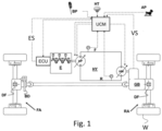
Fig. 1 shows a propulsion diagram of the agricultural or work vehicle of the prior art modified according to the present invention; -
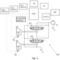
Fig. 2 shows an electro-hydraulic circuit of an agricultural or work vehicle comprising the propulsion scheme according toFig. 1 ; -
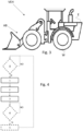
Fig. 3 shows a work vehicle equipped with an articulated arm; -
Fig. 4 shows an exemplary flow diagram of the method object of the present invention. - The same reference numbers and letters in the figures identify the same elements or components or functions.
- It should also be noted that the terms "first", "second", "third", "superior", "inferior" and the like may be used herein to distinguish various elements. These terms do not imply a spatial, sequential, or hierarchical order for the modified items unless specifically indicated or inferred from the text.
- The elements and characteristics illustrated in the various preferred embodiments, including the drawings, can be combined with each other without however departing from the scope of protection of the present application as described below.
- The present invention proposes a control method of the propulsion system of an agricultural or work vehicle VEH, for example according to the scheme of
Figs. 1 and3 of the prior art. The transmission HY comprises an electrically controllable variable displacement hydraulic pump HP and an electrically controllable hydraulic motor HM with fixed or variable displacement. - The shaft of the hydraulic motor is operatively connected to a driving axle RA and/or FA, preferably, but not necessarily, through a discrete ratio gearbox GB. The driving axle can be equipped with a differential DF, which distributes the drive torque to the axle shafts, which drive the wheels W in rotation.
- The hydraulic pump and the hydraulic motor are hydraulically interconnected by a high pressure line F and a low pressure line R, also called delivery line and return line.
- A processing unit ECU is configured to control the operation of the prime mover E, generally an internal combustion engine and more preferably diesel cycled.
- Another processing unit UCM is arranged to control the operation of human/machine interfaces, such as the throttle lever AP, the brake lever BP and the selector position HT to select the park, forward and reverse configurations.
- The processing unit UCM receives as input some parameters including the rotation speed ES of the prime mover E and the vehicle speed VS as well as the signals generated by the man/machine interfaces and manages, among other things, the hydrostat HY and work members such as, for example, an articulated arm AB and the like.
- The hydraulic work members are actuated by means of hydraulic actuators, fed by a dedicated hydraulic circuit, fed by a hydraulic pump driven in rotation by the prime mover E, as shown in
Fig. 2 . -
Fig. 2 shows an example of an electrohydraulic circuit HC. - It has a first and a second open center directional valve V1, V2 for supplying the hydraulic actuators A1 and A2, respectively. There is therefore a laminated hydraulic oil collection tank T.
- The fixed geometry hydraulic pump P feeds the hydraulic circuit HC drawing hydraulic oil from the collection tank T. The pump P is driven in rotation by the prime mover E.
- Therefore, comparing the diagrams of
Figs. 1 and2 , it is understood that the same prime mover E drives in rotation both pumps HP and P, respectively of the hydrostat and of the hydraulic circuit HC. - To speed up an arm handling operation and therefore to increase the productivity of the agricultural or work vehicle, it is necessary to generate a greater flow of hydraulic oil, which is proportional to the rotation speed of the prime mover. It is not possible to increase the rotation speed of the pump P without increasing the rotation speed of the pump HP. Nor is it possible to increase the oil flow by controlling the displacement of the pump P as it has a fixed displacement.
- According to the present invention, when one of the functions is called
- Return to DIG
- Return to Travel
- Return to Height
- Then the rotation speed of the prime mover is automatically increased to allow the pump P to generate a greater flow of hydraulic oil and, at the same time, the hydrostat is adjusted so as to keep the vehicle speed unchanged.
- When the vehicle is stationary, the inclination of the HP hydraulic pump plate is not changed, so that, also in this case, the vehicle speed remains unchanged.
- There is a further function called "Floating" which includes two phases:
- A first stage in which the arm is lowered so as to bring the bucket or fork in a position proximal to the ground,
- A second stage in which both chambers of the boom lifting/lowering actuator A1 are both connected with a hydraulic oil collection tank T. In these conditions, the arm rests naturally on the ground due to the gravitational force.
- The Floating function is similar to one of the return functions limited to the first stage.
- In known hydrostats, at least the hydraulic pump HP has a variable displacement, this means that to keep the flow of oil generated by the hydraulic pump HP constant, its displacement is proportionally reduced, following the same law of increase of the rotation speed of the prime mover.
- At the end of the operation carried out by the hydraulic organ, the rotation speed of the prime mover is restored according to a further law of reduction of the rotation speed and the displacement of the hydraulic pump of the hydrostat is proportionally increased.
- Hydrostats are known in which not only the displacement of the hydraulic pump but also of the hydraulic motor can be controlled. In this case, it is possible to compensate the increase and then the reduction of the rotation speed of the prime mover by acting on the control of the displacement of the hydraulic pump HP - with reduction of the relative displacement - and/or of the hydraulic motor HM - with increase of the relative displacement.
- As described above, all the aforesaid functions are known to those skilled in the art and have in common the fact of automatically repositioning the articulated arm in a pre-stored configuration starting from any different configuration. For convenience, they will be referred, in the followings, as "return functions".
- Obviously, in order to be able to implement the present control, the presence of sensors S1 and S2 associated with the stroke of the actuators A1 and A2 is necessary. Indeed, there is a one-to-one relationship between the stroke of the actuators A1 and A2 and the configuration of the articulated arm.
- Sensors S1 and S2 can also be associated with boom and bucket/fork angle.
- The execution of the method object of the present invention is caused by the activation of any of the aforementioned functions, schematized in
Fig. 2 with the buttons "RTD SWITCH" and/or "RTH SWITCH" and/or "RTT SWITCH" and/or "FLOATING SWITCH". - These buttons are operatively connected with the processing unit UCM described above, as well as the joystick, which allows control of the articulated arm, the accelerator pedal AP and other parameters such as the vehicle speed VS and the rotation speed of the prime mover EX.
- The method object of the present invention provides for the execution of the following steps in succession:
- Step 1: Start execution of return function;
- Step 2: acquisition of the vehicle current speed;
- Step 3: increase the rotation speed of the prime mover and contextual control of the hydrostat to keep the vehicle speed unchanged.
- The same steps are shown in
Fig. 4 according to a possible flow diagram. - The method described here implies that the rotational speed of the prime mover is not under the control of the accelerator pedal as long as the return operation is in progress.
- If, while a return function is in progress, the operator varies the position of the accelerator lever, then, this operation impacts exclusively on the hydrostat and not also on the prime mover.
- For example, if the operator increases depression of the accelerator pedal while performing a return function, then the increase of the angle of the accelerator pedal impacts on the displacement of the hydraulic pump HP, increasing it, and/or the displacement of the hydraulic motor, reducing it. According to a preferred aspect of the present invention, at the end of the return operation, the rotational speed of the prime mover returns under the control of the accelerator pedal.
-
Fig. 4 shows further dashed blocks, indicating that they are optional. For example, in the hypothesis that the present invention is implemented through an independent process, then it comprises a preliminary verification step, Step 0, in which the request for the return of the articulated arm to a prearranged position, for example of DIG, is monitored. When the user actually activates the return function, steps 1 - 3 are performed in succession and the end of the return procedure is monitored, verifying step 4. When this is finished, then step 5 is performed which involves bringing the rotation speed of the prime mover back under the control of the accelerator pedal. - The present invention can advantageously be implemented through a computer program comprising coding means for carrying out one or more steps of the method, when this program is executed on a computer. Therefore, it is understood that the scope of protection extends to said computer program and also to computer-readable means comprising a recorded message, said computer-readable means comprising program coding means for carrying out one or more steps of the method, when said program is run on a computer. Variants of the non-limiting example described are possible, without however departing from the scope of protection of the present invention, including all equivalent embodiments for a person skilled in the art, to the contents of the claims.
- From the description given above, the person skilled in the art is capable of realizing the object of the invention without introducing further constructive details.
Claims (11)
- A method of performing a return function of an articulated boom (AB) of a work or agricultural vehicle (VEH), the return function comprising a procedure of moving the boom from any configuration to a pre-stored configuration,the vehicle being equipped with- a prime mover (E),- an electro-hydraulic circuit (HC) comprising two or more hydraulic actuators (A1, A2) serving the articulated arm, respective open center directional valves (V1, V2) and a hydraulic pump (P) to feed the electro-hydraulic circuit, having fixed displacement, operatively connected to the prime mover to be driven in rotation;- a transmission comprising a hydrostat (HY) comprising a hydraulic pump (HP) and a hydraulic motor (HM) hydraulically connected to the hydraulic pump and arranged to drive a vehicular wheel (W) in rotation;- an accelerator pedal (AP) arranged to control a rotational speed of the prime mover;the method, in response to an activation of the return function, comprising a step of increasing the rotational speed of the prime mover and a simultaneous step of adapting a configuration of the hydrostat so as to maintain unchanged a current vehicle speed.
- The method according to claim 1, further comprising a preliminary step of acquiring a current value of the rotational speed of the prime mover and a current value of the vehicle speed.
- The method according to claim 1 or 2, wherein said return function is one among- Return to DIG- Return to Travel- Return to Height- Floating, limited to the arm lowering phase until an arm tool is brought into a proximal position to the ground.
- The method according to any one of the preceding claims, wherein an action on the accelerator pedal during an execution of the return function causes a change in the current configuration of the hydrostat without changing a current rotational speed of the prime mover.
- The method according to any one of the preceding claims, wherein, in response to the complete execution of the return function, the rotational speed of the prime mover is a function of a current position of the accelerator pedal.
- Method according to any one of the preceding claims, wherein said step of increasing the rotation speed of the prime mover brings the prime mover to a prearranged settable rotation speed.
- Method according to any one of the preceding claims, wherein said increase in rotation speed of the prime mover is performed according to a ramp.
- The method according to any one of claims 5 - 7, wherein, in response to the complete execution of the return function, the rotational speed of the prime mover is varied to correspond to a position of the accelerator lever according to a ramp.
- System for performing a return function of an articulated arm (AB) of a work or agricultural vehicle (VEH), the return function comprising a procedure of moving the arm from any configuration to a pre-stored configuration,the vehicle being equipped with- a prime mover (E),- an electro-hydraulic circuit (HC) comprising two or more hydraulic actuators (A1, A2) serving the articulated arm, respective open center directional valves (V1, V2) and a hydraulic pump (P) to feed the electro-hydraulic circuit, fixed displacement, operatively connected to the prime mover to be driven in rotation;- a transmission comprising a hydrostat (HY) comprising a hydraulic pump (HP) and a hydraulic motor (HM) hydraulically connected to the hydraulic pump and arranged to drive a vehicular wheel (W) in rotation;- an accelerator pedal (AP) arranged to control a rotational speed of the prime mover;the system comprising processing means (UCM) configured to manage said feedback function and configured to increase the rotation speed of the prime mover and contextually adapt a configuration of the hydrostat so as to maintain a current speed of the vehicle unchanged, in response to the activation of this return function.
- System according to claim 9, wherein said processing means are configured to perform all the steps of any one of claims 1 to 8.
- Agricultural or work vehicle (VEH) equipped with- a prime mover (E),- an electro-hydraulic circuit (HC) comprising two or more hydraulic actuators (A1, A2) serving the articulated arm, respective open center directional valves (V1, V2) and a hydraulic pump (P) to feed the electro-hydraulic circuit, fixed displacement, operatively connected to the prime mover to be driven in rotation;- a transmission comprising a hydrostat (HY) comprising a hydraulic pump (HP) and a hydraulic motor (HM) hydraulically connected to the hydraulic pump and arranged to drive a vehicular wheel (W) in rotation;- an accelerator pedal (AP) arranged to control a rotational speed of the prime mover;- processing means (UCM) configured to manage a return function of the arm from any configuration to a pre-stored configuration and configured to increase the rotation speed of the prime mover and contextually adapt a configuration of the hydrostat so as to keep it unchanged a current vehicle speed, in response to the activation of said feedback function.
Applications Claiming Priority (1)
| Application Number | Priority Date | Filing Date | Title |
|---|---|---|---|
| IT102023000011289A IT202300011289A1 (en) | 2023-06-01 | 2023-06-01 | METHOD AND CONTROL SYSTEM FOR THE ACTUATION OF A RETURN FUNCTION OF AN ARTICULATED ARM OF A WORK OR AGRICULTURAL VEHICLE |
Publications (1)
| Publication Number | Publication Date |
|---|---|
| EP4495337A1 true EP4495337A1 (en) | 2025-01-22 |
Family
ID=87514132
Family Applications (1)
| Application Number | Title | Priority Date | Filing Date |
|---|---|---|---|
| EP24179298.5A Pending EP4495337A1 (en) | 2023-06-01 | 2024-05-31 | Method and control system for actuating a return function of an articulated arm of a work or agricultural vehicle |
Country Status (2)
| Country | Link |
|---|---|
| EP (1) | EP4495337A1 (en) |
| IT (1) | IT202300011289A1 (en) |
Citations (3)
| Publication number | Priority date | Publication date | Assignee | Title |
|---|---|---|---|---|
| US20020073833A1 (en) | 2000-12-18 | 2002-06-20 | Coombs Edwin G. | Return to dig system |
| JP2012188861A (en) * | 2011-03-10 | 2012-10-04 | Yanmar Co Ltd | Working vehicle |
| US20210087777A1 (en) * | 2019-09-25 | 2021-03-25 | Deere & Company | Work implement linkage system having automated features for a work vehicle |
-
2023
- 2023-06-01 IT IT102023000011289A patent/IT202300011289A1/en unknown
-
2024
- 2024-05-31 EP EP24179298.5A patent/EP4495337A1/en active Pending
Patent Citations (3)
| Publication number | Priority date | Publication date | Assignee | Title |
|---|---|---|---|---|
| US20020073833A1 (en) | 2000-12-18 | 2002-06-20 | Coombs Edwin G. | Return to dig system |
| JP2012188861A (en) * | 2011-03-10 | 2012-10-04 | Yanmar Co Ltd | Working vehicle |
| US20210087777A1 (en) * | 2019-09-25 | 2021-03-25 | Deere & Company | Work implement linkage system having automated features for a work vehicle |
Also Published As
| Publication number | Publication date |
|---|---|
| IT202300011289A1 (en) | 2024-12-01 |
Similar Documents
| Publication | Publication Date | Title |
|---|---|---|
| JP6049758B2 (en) | Achieving maximum lifting speed using a single input | |
| EP3933121A1 (en) | System for controlling a propulsion system of a work or agricultural vehicle | |
| EP3421845A1 (en) | Work vehicle | |
| US8290672B2 (en) | Method and a system for controlling a vehicle | |
| US8825323B2 (en) | Machine control system implementing speed-based clutch modulation | |
| EP3294581B1 (en) | A working machine arranged with means to drive and control a hydraulic pump | |
| EP3652025B1 (en) | Inching system for a construction vehicle | |
| EP2910396B1 (en) | Operation vehicle travel control device | |
| EP4176139B1 (en) | Control system of an arm of a loader vehicle (cwl) | |
| US20140041471A1 (en) | Automatic shift of mechanical gearbox | |
| EP3719356B1 (en) | Hydrostatic transmission for a work vehicle provided with a system for reducing the jerk during direction inversion manoeuvres | |
| US11459731B2 (en) | Working machine | |
| JP2003185006A (en) | Work vehicle shift control device | |
| EP4575103A1 (en) | Method for operating a hydraulic circuit of a work vehicle, corresponding processing unit and work vehicle | |
| IT202300015090A1 (en) | METHOD AND CONTROL SYSTEM FOR THE ACTUATION OF A RETURN FUNCTION OF AN ARTICULATED ARM OF A WORK OR AGRICULTURAL VEHICLE | |
| EP4542089A1 (en) | Method and control system for a propulsion system of a work or agricultural vehicle | |
| EP4177406B1 (en) | Working machine and method of changing the driving direction of such working machine | |
| EP4563848A1 (en) | Method and control system for controlling a propulsion system of a propulsion system of a work or agricultural vehicle | |
| EP4299952B1 (en) | Control system of a hydraulic transmission of a work or agricultural vehicle | |
| AU2019272061B2 (en) | Braking system for machine | |
| EP4375104B1 (en) | Method and system for controlling a propulsion system of a work or agricultural vehicle | |
| CN113906184A (en) | Load carrying vehicle | |
| US20240076852A1 (en) | Utility Vehicle with Automatic Shift Control | |
| US20240309611A1 (en) | Method and system for controlling a propulsion system of a work or agricultural vehicle | |
| EP4286228B1 (en) | High torque braking system |
Legal Events
| Date | Code | Title | Description |
|---|---|---|---|
| PUAI | Public reference made under article 153(3) epc to a published international application that has entered the european phase |
Free format text: ORIGINAL CODE: 0009012 |
|
| STAA | Information on the status of an ep patent application or granted ep patent |
Free format text: STATUS: THE APPLICATION HAS BEEN PUBLISHED |
|
| AK | Designated contracting states |
Kind code of ref document: A1 Designated state(s): AL AT BE BG CH CY CZ DE DK EE ES FI FR GB GR HR HU IE IS IT LI LT LU LV MC ME MK MT NL NO PL PT RO RS SE SI SK SM TR |
|
| STAA | Information on the status of an ep patent application or granted ep patent |
Free format text: STATUS: REQUEST FOR EXAMINATION WAS MADE |
|
| 17P | Request for examination filed |
Effective date: 20250722 |
|
| RIC1 | Information provided on ipc code assigned before grant |
Ipc: E02F 9/20 20060101AFI20260408BHEP Ipc: E02F 9/22 20060101ALI20260408BHEP Ipc: E02F 9/26 20060101ALI20260408BHEP Ipc: F16H 61/47 20100101ALI20260408BHEP Ipc: F16H 63/50 20060101ALI20260408BHEP |
|
| GRAP | Despatch of communication of intention to grant a patent |
Free format text: ORIGINAL CODE: EPIDOSNIGR1 |
|
| STAA | Information on the status of an ep patent application or granted ep patent |
Free format text: STATUS: GRANT OF PATENT IS INTENDED |
|
| GRAJ | Information related to disapproval of communication of intention to grant by the applicant or resumption of examination proceedings by the epo deleted |
Free format text: ORIGINAL CODE: EPIDOSDIGR1 |
|
| STAA | Information on the status of an ep patent application or granted ep patent |
Free format text: STATUS: REQUEST FOR EXAMINATION WAS MADE |
|
| INTG | Intention to grant announced |
Effective date: 20260527 |
|
| GRAP | Despatch of communication of intention to grant a patent |
Free format text: ORIGINAL CODE: EPIDOSNIGR1 |
|
| STAA | Information on the status of an ep patent application or granted ep patent |
Free format text: STATUS: GRANT OF PATENT IS INTENDED |
|
| INTC | Intention to grant announced (deleted) | ||
| INTG | Intention to grant announced |
Effective date: 20260703 |