EP4495329A1 - Improved end stop mechanism for a work vehicle - Google Patents
Improved end stop mechanism for a work vehicle Download PDFInfo
- Publication number
- EP4495329A1 EP4495329A1 EP24189058.1A EP24189058A EP4495329A1 EP 4495329 A1 EP4495329 A1 EP 4495329A1 EP 24189058 A EP24189058 A EP 24189058A EP 4495329 A1 EP4495329 A1 EP 4495329A1
- Authority
- EP
- European Patent Office
- Prior art keywords
- arm
- actuator
- work vehicle
- axis
- rotatably connected
- Prior art date
- Legal status (The legal status is an assumption and is not a legal conclusion. Google has not performed a legal analysis and makes no representation as to the accuracy of the status listed.)
- Pending
Links
Images


Classifications
-
- E—FIXED CONSTRUCTIONS
- E02—HYDRAULIC ENGINEERING; FOUNDATIONS; SOIL SHIFTING
- E02F—DREDGING; SOIL-SHIFTING
- E02F3/00—Dredgers; Soil-shifting machines
- E02F3/04—Dredgers; Soil-shifting machines mechanically-driven
- E02F3/28—Dredgers; Soil-shifting machines mechanically-driven with digging tools mounted on a dipper- or bucket-arm, i.e. there is either one arm or a pair of arms, e.g. dippers, buckets
- E02F3/30—Dredgers; Soil-shifting machines mechanically-driven with digging tools mounted on a dipper- or bucket-arm, i.e. there is either one arm or a pair of arms, e.g. dippers, buckets with a dipper-arm pivoted on a cantilever beam, i.e. boom
- E02F3/308—Dredgers; Soil-shifting machines mechanically-driven with digging tools mounted on a dipper- or bucket-arm, i.e. there is either one arm or a pair of arms, e.g. dippers, buckets with a dipper-arm pivoted on a cantilever beam, i.e. boom working outwardly
-
- E—FIXED CONSTRUCTIONS
- E02—HYDRAULIC ENGINEERING; FOUNDATIONS; SOIL SHIFTING
- E02F—DREDGING; SOIL-SHIFTING
- E02F3/00—Dredgers; Soil-shifting machines
- E02F3/04—Dredgers; Soil-shifting machines mechanically-driven
- E02F3/28—Dredgers; Soil-shifting machines mechanically-driven with digging tools mounted on a dipper- or bucket-arm, i.e. there is either one arm or a pair of arms, e.g. dippers, buckets
- E02F3/34—Dredgers; Soil-shifting machines mechanically-driven with digging tools mounted on a dipper- or bucket-arm, i.e. there is either one arm or a pair of arms, e.g. dippers, buckets with bucket-arms, i.e. a pair of arms, e.g. manufacturing processes, form, geometry, material of bucket-arms directly pivoted on the frames of tractors or self-propelled machines
- E02F3/3405—Dredgers; Soil-shifting machines mechanically-driven with digging tools mounted on a dipper- or bucket-arm, i.e. there is either one arm or a pair of arms, e.g. dippers, buckets with bucket-arms, i.e. a pair of arms, e.g. manufacturing processes, form, geometry, material of bucket-arms directly pivoted on the frames of tractors or self-propelled machines and comprising an additional linkage mechanism
-
- E—FIXED CONSTRUCTIONS
- E02—HYDRAULIC ENGINEERING; FOUNDATIONS; SOIL SHIFTING
- E02F—DREDGING; SOIL-SHIFTING
- E02F3/00—Dredgers; Soil-shifting machines
- E02F3/04—Dredgers; Soil-shifting machines mechanically-driven
- E02F3/28—Dredgers; Soil-shifting machines mechanically-driven with digging tools mounted on a dipper- or bucket-arm, i.e. there is either one arm or a pair of arms, e.g. dippers, buckets
- E02F3/36—Component parts
- E02F3/38—Cantilever beams, i.e. booms;, e.g. manufacturing processes, forms, geometry or materials used for booms; Dipper-arms, e.g. manufacturing processes, forms, geometry or materials used for dipper-arms; Bucket-arms
- E02F3/388—Mechanical locking means for booms or arms against rotation, e.g. during transport of the machine
-
- E—FIXED CONSTRUCTIONS
- E02—HYDRAULIC ENGINEERING; FOUNDATIONS; SOIL SHIFTING
- E02F—DREDGING; SOIL-SHIFTING
- E02F9/00—Component parts of dredgers or soil-shifting machines, not restricted to one of the kinds covered by groups E02F3/00 - E02F7/00
- E02F9/20—Drives; Control devices
- E02F9/22—Hydraulic or pneumatic drives
- E02F9/226—Safety arrangements, e.g. hydraulic driven fans, preventing cavitation, leakage, overheating
Definitions
- the present invention concerns a work vehicle.
- the present invention finds its preferred, although not exclusive, application in an agricultural vehicle, such as a tractor.
- an agricultural vehicle such as a tractor, may comprise a loading device, e.g. a front loading device, configured to hold and move material, e.g. earth, sand, rocks, pallets, logs.
- the loading device comprises one or more arms and a tool, e.g. a scoop or bucket, a pallet handler, a log handler.
- the tool is movable, via actuators, along a semicircular trajectory between a lower position and an upper position.
- the publication IT201900005800A1 discloses a work vehicle wherein the tool is movable along a straight trajectory, in particular a vertical trajectory, between a lower position and an upper position. This is achieved by providing the work vehicle with additional components so as to increase its degrees of freedom. However, the higher the number of components, the higher the risk of collisions. This can also lead to safety issues.
- An aim of the present invention is to satisfy the above-mentioned need in a cost-effective and optimised manner.
- Figures 1 and 2 illustrate respective operating positions of a work vehicle 1.
- the work vehicle 1 is of known type and comprises a vehicle body having a front portion 3, a rear portion 4, and a cabin 5 interposed therebetween. Conveniently, the work vehicle 1 comprises front tyres 6 arranged in the front portion 3 and rear tyres 7 arranged in the rear portion 4.
- the work vehicle 1 comprises a loader connection frame 11, carried by the front portion 3, and a loading device 12 connected thereto, in particular a front loading device 12 in the illustrated embodiment.
- the front loading device 12 comprises a first arm 21 rotatably connected to the loader connection frame 11, a second arm 22 rotatably connected to the first arm 21, and a tool 23 rotatably connected to the second arm 22.
- the tool 23 is movable between a lower position and an upper position.
- the work vehicle 1 is on a horizontal plane P, e.g. on a horizontal ground 24, and the tool 23 is in contact with the plane P in its lower position ( figure 1 ) and vertically above, i.e. above orthogonally to the plane P, in its upper position ( figure 2 ).
- the work vehicle 1 comprises a plurality of actuators configured to actuate the components of the front loading device 12.
- the work vehicle 1 comprises a first actuator 31 configured to actuate the first arm 21, a second actuator 32 configured to actuate the second arm 22, and a third actuator 33 configured to actuate the tool 23.
- the first arm 21 is carried by the loader connection frame 11 and rotatable with respect thereto about the first axis A1 under the thrust of the first actuator 31
- the second arm 22 is carried by the first arm 21 and rotatable with respect thereto about the second axis A1 under the thrust of the second actuator 32
- the tool 23 is carried by the second arm 22 and rotatable with respect thereto about the third axis A3 under the thrust of the third actuator 33.
- the first arm 21 has a first end portion 21a rotatably connected to the loader connection frame 11
- the second arm 22 has a first end portion 22a rotatably connected to a second end portion 21b of the first arm 21
- the tool 23 has a connecting portion 23a rotatably connected to a second end portion 22b of the second arm 22.
- first axis A1 is stationary with respect to the loader connection frame 11
- second axis A2 is stationary with respect to the second end portion 21b of the first arm 21
- third axis A3 is stationary with respect to second end portion 22b of the second arm 22.
- the first-actuator first axis A11, the first-actuator second axis A12, the second-actuator first axis A21, the second-actuator second axis A22, the third-actuator first axis A31, the third-actuator second axis A32 are parallel to one another and to the first axis A1, the second axis A2 and the third axis A3.
- the first-actuator first axis A11, the first-actuator second axis A12, the second-actuator second axis A22, the third-actuator first axis A31, the third-actuator second axis A32 are distinct from one another.
- the first-actuator second axis A12 and the second-actuator first axis A21 are coincident.
- the second arm 22 is interposed between the second actuator 32 and the third actuator 33.
- the work vehicle 1 comprises an electronic control unit (not illustrated) configured to control the rotation of the first arm 21 about the first axis A1 by acting on the first actuator 31, the rotation of the second arm 2 about the second axis A2 by acting on the second actuator 32 and the rotation of the tool 23 about the third axis A3 by acting on the third actuator 33 so that the tool 23 moves along a predetermined trajectory.
- the electronic control unit is configured to calculate the rotations of the first arm 21, the second arm 22 and the tool 23 via inverse kinematics algorithms based on sensors data acquired by sensor means (not shown) configured to retrieve the position of the first arm 21.
- sensor means can be position sensor or angular sensors.
- the electronic control unit is configured to control the first actuator 31, the second actuator 32 and the third actuator 33, which in turn actuate, respectively, the first arm 21, the second arm 22 and the tool 23, thus ultimately defining the trajectory of the tool 23.
- the relationship between the movement of an actuator, e.g. the first actuator 31, and the resulting rotation of the respective actuated component, e.g. the first arm 21, about the respective axis, e.g. the first axis A1, is known.
- the electronic control unit is configured to calculate the rotations of the first arm 21, the second arm 22 and the tool 23.
- the electronic control unit is configured to calculate the movements of the first actuator 31, the second actuator 32 and the third actuator 33.
- the trajectory of the tool 23 can be calculated via direct kinematics algorithms.
- the rotations of the first arm 21, the second arm 22 and the tool 23 can be calculated via inverse kinematics algorithms.
- the predetermined trajectory is a straight trajectory.
- the tool 23 moves along a straight line, i.e. each point of the tool 23 defines a straight line while moving.
- the predetermined trajectory is orthogonal to the plane P but other predetermine trajectory can be provided, such as a trajectory parallel to plane P when the tool 23 is only moved upwards or downwards.
- the predetermined trajectory is a vertical trajectory.
- the tool 23 moves along a vertical trajectory, i.e. each point of the tool 23 defines a vertical line while moving.
- the predetermined trajectory is orthogonal to the plane P, which is horizontal.
- the work vehicle 1 comprises an end stop mechanism 41 configured to cooperate with each of the loader connection frame 11, the first arm 21 and the second arm 22.
- the end stop mechanism 41 is carried by the first arm 21.
- end stop mechanism 41 is carried by the appendage 34 of the first arm 21.
- the end stop mechanism 41 is slidably coupled to the first arm 21.
- the end stop mechanism 41 is slidable with respect to the appendage 34 of the first arm 21.
- the end stop mechanism 41 is coupled to one of the loader connection frame 11 and the second arm 22 and configured to cooperate in contact with the other of the loader connection frame 11 and the second arm 22.
- the end stop mechanism 41 is rotatably connected to the loader connection frame 11 and configured to assume a first configuration ( figure 3 ), wherein the end stop mechanism 41 is not in contact with the second arm 22, and a second configuration ( figure 4 ), wherein the end stop mechanism 41 is in contact with the second arm 22.
- the end stop mechanism 41 is switchable between the first configuration and the second configuration.
- the end stop mechanism 41 is hinged to the loader connection frame 11, e.g. via a bearing connection 42, and rotatable with respect to the loader connection frame 11 about a hinge axis H.
- the end stop mechanism 41 is configured to cooperate in contact with the second arm 22, in particular when the end stop mechanism 41 is in the second configuration.
- the end stop mechanism 41 comprises a rod 51 having a first end 51a rotatably connected to the loader connection frame 11 and a second end 51b configured to cooperate in contact with the second arm 22 when the end stop mechanism 41 is in the second configuration.
- the hinge axis H is stationary with respect to the loader connection frame 11.
- the hinge axis H is parallel to the first axis A1.
- the hinge axis H is parallel to the plane P, i.e. it is a horizontal axis.
- the second arm 22 comprises a striker element 52 configured to cooperate in contact with the second end 51b of the rod 51 when the end stop mechanism 41 is in the second configuration.
- the striker element 52 is a welded shaft carried by the second arm 22 and having an axis parallel to the second axis A2.
- the striker element 52 is carried by the first end portion 22a of the second arm 22 and faces the second end 51b of the rod 51.
- the second end portion 22a of the second arm 22 is curved, i.e. has a curved profile, towards the second end 51b of the rod 51 with substantially the same radius of curvature as the striker element 52, whose axis contains the centre of curvature.
- the striker element 52 appears as the osculating circle of a curve at a point, wherein such curve is that defining the curved profile of the second end portion 22a of the second arm 22 and such point is that of contact between the striker element 52 and the second end 51b of the rod 51.
- the first arm 21 comprises a first flanged portion 61, and the rod 51 is slidably coupled to the first flanged portion 61.
- first flanged portion 61 is carried by the appendage 34 and extends, substantially orthogonally to the appendage 34, towards the rod 51, which is slidable with respect to the first flanged portion 61.
- the first flanged portion 61 is interposed between the rod 51 and the first actuator 31.
- the first flanged portion 61 is interposed between the second end 51b of the rod 51 and the second end 31b of the first actuator 31.
- the first flanged portion 61 is configured to slidably carry the rod 51.
- the first flanged portion 61 is realised as a flat bar.
- the first arm 21 comprises a second flanged portion 62, and the rod 51 is slidably coupled to the second flanged portion 62.
- the second flanged portion 62 is carried by the appendage 34 and extends, substantially orthogonally to the appendage 34, towards the rod 51, which is slidable with respect to the second flanged portion 62.
- the second flanged portion 62 is realised as a flat bar.
- the rod 51 is interposed between the first flanged portion 61 and the second flanged portion 62.
- first flanged portion 61 and the second flanged portion 62 are configured to at least partially house the rod 51.
- the first flanged portion 61 and the second flanged portion 62 are rigidly coupled to the appendage 34 of the first arm 21 and are configured to guide the rod 51, which is slidable with respect to both.
- the rod 51 extends along a rod axis R ( figure 7 ) and at least sections 61', 62' of the first flanged portion 61 and the second flanged portion 62 extend parallel to the rod axis R.
- the rod axis R is orthogonal to the hinge axis H.
- the sections 61', 62' of, respectively, the first flanged portion 61 and the second flanged portion 62 extend orthogonally to the appendage 34 and parallel to each other.
- First and second flanged portions 61, 62 are preferably realized in a material configured to avoid friction, i.e. with a material with low friction coefficient in order to allow easy sliding thereon.
- first and second flanged portions 61, 62 can be selectively removed to be replaced in case of excessive wear.
- the second end 51b of the rod 51 comprises a terminal portion 71 facing the striker element 52 of the second arm 22.
- the terminal portion 71 is flat and extends orthogonally to the road axis R.
- the rod 51 is realised as a moulded tube which extends along the rod axis R and has a rectangular cross section, e.g. a square cross section.
- the first flanged portion 61 and the second flanged portion 62 face opposite faces 81, 82 of the rod 51 extending orthogonally to the appendage 34, and the sections 61', 62' extend parallel to, respectively, the faces 81, 82.
- first flanged portion 61 and the second flanged portion 62 have respective surfaces 91, 92 configured to cooperate in contact with the rod 51 and made of an anti-friction material.
- the surfaces 91, 92 are respective coatings of at least the sections 61', 62' of, respectively, the first flanged portion 61 and the second flanged portion 62.
- the surfaces 91, 92 are made of the same anti-friction material.
- the surfaces 91, 92 are made of a synthetic anti-friction material, e.g. selected from the group comprising PTFE, PEEK, PPS, nylon, acetal, polyester.
- the surface 91 of the first flanged portion 61 is configured to cooperate in contact with the face 81 of the rod 51 and the surface 92 of the second flanged portion 62 is configured to cooperate in contact with the face 82 of the rod 51.
- the rod 51 is slidable with respect to the surfaces 91, 92.
- the tool 23 moves along a trajectory because the first arm 21 rotates about the first axis A1 via the first actuator 31, the second arm 22 rotates about the second axis A2 via the second actuator 32, and the tool 23 rotates about the third axis A3 via the third actuator 33.
- the electronic control unit calculates the rotations of the first arm 21, the second arm 22 and the tool 23 via inverse kinematics algorithms and actuates the first actuator 31, the second actuator 32 and the third actuator 33 so that the tool 23 moves along a predetermined trajectory.
- the end stop mechanism 41 rotates about the hinge axis H because is slidably carried by the first arm 21.
- the rod 51 of the end stop mechanism 41 is brought into rotation by the first arm 21 and slides with respect to the first flanged portion 61 and the second flanged portion 62.
- the end stop mechanism 41 switches between the first configuration ( figure 3 ), wherein the end stop mechanism 41 is not in contact with the second arm 22 ( figure 5 ), and a second configuration ( figure 4 ), wherein the end stop mechanism 41 is in contact with the second arm 22 ( figure 6 ).
- a possible reason why the end stop mechanism 41 switches from the first configuration to the second configuration is that the first actuator 31, the second actuator 32 and the third actuator 33 are hydraulic cylinders, which get compressed in case of hydraulic overload.
- the end stop mechanism 41 switches from the first configuration to the second configuration, i.e. the end stop mechanism 41 and the second arm 22 get in contact, thus stopping relative motion therebetween and avoiding damages to the work vehicle 1, e.g. to the front portion 3, the loader connection frame 11, the first arm 21, the second arm 22, the tool 23.
- the striker element 52 of the second arm 22 abuts against the terminal portion 71 of the second end 51b of the rod 51 when the end stop mechanism 41 switches from the first configuration to the second configuration.
- the end stop mechanism 41 switches from the second configuration to the first configuration, i.e. the end stop mechanism 41 and the second arm 22 are no longer in contact, thus allowing relative motion therebetween.
- the striker element 52 of the second arm 22 moves away from the terminal portion 71 of the second end 51b of the rod 51 when the end stop mechanism 41 switches from the second configuration to the first configuration.
- the end stop mechanism 41 allows to protect the work vehicle 1 from damages, thus also increasing safety, by cooperating with each of the first arm 21, the second arm 22 and the tool 23.
- the load capacity pushing is increased. Indeed, in known systems without the end stop, the pushing load capacity, when pushing material, is lower, because the cylinder will have overload and is pushed back. Conversely, thanks to the present invention, the pushing capacity is higher since the frame is in contact with the end stop by overload instead of cylinders as in the prior art.
- the end stop mechanism 41 is rotatably connected to the loader connection frame 11, is slidably carried by the first arm 21 and cooperates in contact with the second arm 22, in particular when the end stop mechanism 41 is in the second configuration.
- the end stop mechanism 41 rotatably cooperates with the loader connection frame 11, slidably cooperates with the first arm 21 and cooperates in contact with the second arm 22, in particular when the end stop mechanism 41 is in the second configuration.
- the shape of the components may be different from that described or the loading device may be a rear loading device.
- end stop mechanism 41 may be coupled to the second arm 22 and configured to cooperate in contact with the loader connection frame 11.
- stricter element 52 can be also configured differently from a welded tube, i.e. being a mold tube or a edged shape or a welded shape.
- rod 51 can have a different shape or cross-section.
Landscapes
- Engineering & Computer Science (AREA)
- Mechanical Engineering (AREA)
- Mining & Mineral Resources (AREA)
- Civil Engineering (AREA)
- General Engineering & Computer Science (AREA)
- Structural Engineering (AREA)
- Agricultural Machines (AREA)
- Manipulator (AREA)
Abstract
Description
- The present invention concerns a work vehicle.
- The present invention finds its preferred, although not exclusive, application in an agricultural vehicle, such as a tractor.
- As is known, an agricultural vehicle, such as a tractor, may comprise a loading device, e.g. a front loading device, configured to hold and move material, e.g. earth, sand, rocks, pallets, logs. The loading device comprises one or more arms and a tool, e.g. a scoop or bucket, a pallet handler, a log handler. The tool is movable, via actuators, along a semicircular trajectory between a lower position and an upper position.
- The publication
IT201900005800A1 - Therefore, the need is felt to improve known work vehicles so as to protect them from damages and increase safety.
- An aim of the present invention is to satisfy the above-mentioned need in a cost-effective and optimised manner.
- The aforementioned aim is reached by a work vehicle as claimed in the appended set of claims.
- For a better understanding of the present invention, a preferred embodiment is described in the following, by way of a non-limiting example, with reference to the attached drawings wherein:
-
Figures 1 and 2 are side views of a work vehicle according to the invention in different operating positions; -
Figures 3 and 4 are side views of components of the work vehicle in respective configurations; -
Figures 5 and 6 are side views, in enlarged scales, of details offigures 3 and 4 , respectively; -
Figure 7 is a perspective cross-sectional view, in enlarged scale, of components of the work vehicle. -
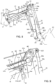
Figures 8 and 9 are side vires of details of components of the work vehicle in further respective configurations. -
Figures 1 and 2 illustrate respective operating positions of awork vehicle 1. - The
work vehicle 1 is of known type and comprises a vehicle body having afront portion 3, arear portion 4, and acabin 5 interposed therebetween. Conveniently, thework vehicle 1 comprisesfront tyres 6 arranged in thefront portion 3 andrear tyres 7 arranged in therear portion 4. - The
work vehicle 1 comprises aloader connection frame 11, carried by thefront portion 3, and aloading device 12 connected thereto, in particular afront loading device 12 in the illustrated embodiment. - The
front loading device 12 comprises afirst arm 21 rotatably connected to theloader connection frame 11, asecond arm 22 rotatably connected to thefirst arm 21, and atool 23 rotatably connected to thesecond arm 22. - The
tool 23 is movable between a lower position and an upper position. - In the illustrated embodiment, the
work vehicle 1 is on a horizontal plane P, e.g. on ahorizontal ground 24, and thetool 23 is in contact with the plane P in its lower position (figure 1 ) and vertically above, i.e. above orthogonally to the plane P, in its upper position (figure 2 ). - Conveniently, the
work vehicle 1 comprises a plurality of actuators configured to actuate the components of thefront loading device 12. - In particular, the
work vehicle 1 comprises afirst actuator 31 configured to actuate thefirst arm 21, asecond actuator 32 configured to actuate thesecond arm 22, and athird actuator 33 configured to actuate thetool 23. - Preferably (figured 3 and 4), the
first actuator 31 is configured to cause rotation of thefirst arm 21 about a first axis A1, thesecond actuator 32 is configured to cause rotation of thesecond arm 22 about a second axis A2, and thethird actuator 33 is configured to cause rotation of thetool 23 about a third axis A3. The first axis A1, the second axis A2 and the third axis A3 are parallel to one another. Conveniently, the first axis A1, the second axis A2 and the third axis A3 are parallel to the plane P, i.e. they are horizontal axes. - In particular, the
first arm 21 is carried by theloader connection frame 11 and rotatable with respect thereto about the first axis A1 under the thrust of thefirst actuator 31, thesecond arm 22 is carried by thefirst arm 21 and rotatable with respect thereto about the second axis A1 under the thrust of thesecond actuator 32, and thetool 23 is carried by thesecond arm 22 and rotatable with respect thereto about the third axis A3 under the thrust of thethird actuator 33. - Conveniently, the
first arm 21 has afirst end portion 21a rotatably connected to theloader connection frame 11, thesecond arm 22 has afirst end portion 22a rotatably connected to asecond end portion 21b of thefirst arm 21, and thetool 23 has a connectingportion 23a rotatably connected to asecond end portion 22b of thesecond arm 22. - In particular, the first axis A1 is stationary with respect to the
loader connection frame 11, the second axis A2 is stationary with respect to thesecond end portion 21b of thefirst arm 21, and the third axis A3 is stationary with respect tosecond end portion 22b of thesecond arm 22. - Preferably, the
first actuator 31 is a first hydraulic cylinder having afirst end 31a rotatably connected to theloader connection frame 11 and asecond end 31b rotatably connected to anappendage 34 extending from thesecond end portion 21b of thefirst arm 21, thesecond actuator 32 is a second hydraulic cylinder having afirst end 32a rotatably connected to theappendage 34 and asecond end 32b rotatably connected to thesecond end portion 22b of thesecond arm 22, thethird actuator 33 is a third hydraulic cylinder having afirst end 33a rotatably connected to thefirst end portion 22a of thesecond arm 22 and asecond end 33b rotatably connected to thetool 23. - In particular, the
first end 31a of thefirst actuator 31 is hinged to theloader connection frame 11 and rotatable with respect thereto about a first-actuator first axis A11, thesecond end 31b of thefirst actuator 31 is hinged to theappendage 34 and rotatable with respect thereto about a first-actuator second axis A12, thefirst end 32a of thesecond actuator 32 is hinged to theappendage 34 and rotatable with respect thereto about a second-actuator first axis A21, thesecond end 32b of thesecond actuator 32 is hinged to thesecond end portion 22b of thesecond arm 22 and rotatable with respect thereto about a second-actuator second axis A22, thefirst end 33a of thethird actuator 33 is hinged to thefirst end portion 22a of thesecond arm 22 and rotatable with respect thereto about a third-actuator first axis A31, thesecond end 33b of thethird actuator 33 is hinged to thetool 23 and rotatable with respect thereto about a third-actuator second axis A32. The first-actuator first axis A11, the first-actuator second axis A12, the second-actuator first axis A21, the second-actuator second axis A22, the third-actuator first axis A31, the third-actuator second axis A32 are parallel to one another and to the first axis A1, the second axis A2 and the third axis A3. The first-actuator first axis A11, the first-actuator second axis A12, the second-actuator second axis A22, the third-actuator first axis A31, the third-actuator second axis A32 are distinct from one another. The first-actuator second axis A12 and the second-actuator first axis A21 are coincident. - Conveniently, from a side view (
figures 1 to 4 ), thesecond arm 22 is interposed between thesecond actuator 32 and thethird actuator 33. - Preferably, the
appendage 34 is a plate extending towards thefront portion 3 of thework vehicle 1. In the illustrated embodiment, theappendage 34 extends vertically and in particular downwards, i.e. towards the plane P, when thetool 23 is in its lower position (figure 1 ). - Conveniently, the
work vehicle 1 comprises an electronic control unit (not illustrated) configured to control the rotation of thefirst arm 21 about the first axis A1 by acting on thefirst actuator 31, the rotation of the second arm 2 about the second axis A2 by acting on thesecond actuator 32 and the rotation of thetool 23 about the third axis A3 by acting on thethird actuator 33 so that thetool 23 moves along a predetermined trajectory. The electronic control unit is configured to calculate the rotations of thefirst arm 21, thesecond arm 22 and thetool 23 via inverse kinematics algorithms based on sensors data acquired by sensor means (not shown) configured to retrieve the position of thefirst arm 21. Example of such sensor means can be position sensor or angular sensors. - In particular, the electronic control unit is configured to control the
first actuator 31, thesecond actuator 32 and thethird actuator 33, which in turn actuate, respectively, thefirst arm 21, thesecond arm 22 and thetool 23, thus ultimately defining the trajectory of thetool 23. - Conveniently, the relationship between the movement of an actuator, e.g. the
first actuator 31, and the resulting rotation of the respective actuated component, e.g. thefirst arm 21, about the respective axis, e.g. the first axis A1, is known. - In particular, if the movements of the
first actuator 31, thesecond actuator 32 and thethird actuator 33 are known, the electronic control unit is configured to calculate the rotations of thefirst arm 21, thesecond arm 22 and thetool 23. Vice versa, if the rotations of thefirst arm 21, thesecond arm 22 and thetool 23 are known, the electronic control unit is configured to calculate the movements of thefirst actuator 31, thesecond actuator 32 and thethird actuator 33. - Conveniently, the relationship between the rotations of the actuated components about the respective axes and the trajectory of the
tool 23 is known. - In particular, if the rotations of the
first arm 21, thesecond arm 22 and thetool 23 are known, the trajectory of thetool 23 can be calculated via direct kinematics algorithms. Vice versa, if the trajectory of thetool 23 is known, the rotations of thefirst arm 21, thesecond arm 22 and thetool 23 can be calculated via inverse kinematics algorithms. - In the illustrated embodiment, the trajectory of the
tool 23 can be selected and is thus known, the electronic control unit is configured to calculate the rotations of thefirst arm 21, thesecond arm 22 and thetool 23 via inverse kinematics algorithms, and to calculate the movements of, and thus control, thefirst actuator 31, thesecond actuator 32 and thethird actuator 33. - Conveniently, the predetermined trajectory is a straight trajectory. In other words, the
tool 23 moves along a straight line, i.e. each point of thetool 23 defines a straight line while moving. In the illustrated embodiment, the predetermined trajectory is orthogonal to the plane P but other predetermine trajectory can be provided, such as a trajectory parallel to plane P when thetool 23 is only moved upwards or downwards. - Preferably, the predetermined trajectory is a vertical trajectory. In other words, the
tool 23 moves along a vertical trajectory, i.e. each point of thetool 23 defines a vertical line while moving. In the illustrated embodiment, the predetermined trajectory is orthogonal to the plane P, which is horizontal. - The
work vehicle 1 comprises anend stop mechanism 41 configured to cooperate with each of theloader connection frame 11, thefirst arm 21 and thesecond arm 22. - Preferably, the
end stop mechanism 41 is carried by thefirst arm 21. - In particular, the
end stop mechanism 41 is carried by theappendage 34 of thefirst arm 21. - Preferably, the
end stop mechanism 41 is slidable with respect to thefirst arm 21. - In particular, the
end stop mechanism 41 is slidably coupled to thefirst arm 21. Preferably, theend stop mechanism 41 is slidable with respect to theappendage 34 of thefirst arm 21. - Conveniently, the
end stop mechanism 41 is coupled to one of theloader connection frame 11 and thesecond arm 22 and configured to cooperate in contact with the other of theloader connection frame 11 and thesecond arm 22. - Preferably, the
end stop mechanism 41 is rotatably connected to theloader connection frame 11 and configured to assume a first configuration (figure 3 ), wherein theend stop mechanism 41 is not in contact with thesecond arm 22, and a second configuration (figure 4 ), wherein theend stop mechanism 41 is in contact with thesecond arm 22. Conveniently, theend stop mechanism 41 is switchable between the first configuration and the second configuration. - In particular, the
end stop mechanism 41 is hinged to theloader connection frame 11, e.g. via abearing connection 42, and rotatable with respect to theloader connection frame 11 about a hinge axis H. Theend stop mechanism 41 is configured to cooperate in contact with thesecond arm 22, in particular when theend stop mechanism 41 is in the second configuration. - Conveniently, the
end stop mechanism 41 comprises arod 51 having afirst end 51a rotatably connected to theloader connection frame 11 and asecond end 51b configured to cooperate in contact with thesecond arm 22 when theend stop mechanism 41 is in the second configuration. - In particular, the hinge axis H is stationary with respect to the
loader connection frame 11. The hinge axis H is parallel to the first axis A1. Conveniently, the hinge axis H is parallel to the plane P, i.e. it is a horizontal axis. - Conveniently, from a side view (
figures 1 to 4 ), therod 51 is interposed between thefirst arm 21 and thefirst actuator 31. Therod 51 is dimensioned and arranged so as to have a predetermined relative position between thefirst arm 21 and thesecond arm 22 when theend stop mechanism 41 is in the second configuration (figure 4 ). - Preferably, the
second arm 22 comprises astriker element 52 configured to cooperate in contact with thesecond end 51b of therod 51 when theend stop mechanism 41 is in the second configuration. - In particular, the
striker element 52 is a welded shaft carried by thesecond arm 22 and having an axis parallel to the second axis A2. Conveniently, thestriker element 52 is carried by thefirst end portion 22a of thesecond arm 22 and faces thesecond end 51b of therod 51. Preferably (figures 3 and 4 ), thesecond end portion 22a of thesecond arm 22 is curved, i.e. has a curved profile, towards thesecond end 51b of therod 51 with substantially the same radius of curvature as thestriker element 52, whose axis contains the centre of curvature. In other words, from a side view (figures 5 and 6 ), thestriker element 52 appears as the osculating circle of a curve at a point, wherein such curve is that defining the curved profile of thesecond end portion 22a of thesecond arm 22 and such point is that of contact between thestriker element 52 and thesecond end 51b of therod 51. - Preferably, the
first arm 21 comprises a firstflanged portion 61, and therod 51 is slidably coupled to the firstflanged portion 61. - In particular, the first
flanged portion 61 is carried by theappendage 34 and extends, substantially orthogonally to theappendage 34, towards therod 51, which is slidable with respect to the firstflanged portion 61. - Conveniently, the first
flanged portion 61 is interposed between therod 51 and thefirst actuator 31. In particular, the firstflanged portion 61 is interposed between thesecond end 51b of therod 51 and thesecond end 31b of thefirst actuator 31. The firstflanged portion 61 is configured to slidably carry therod 51. - In the illustrated embodiment (
figure 7 ), the firstflanged portion 61 is realised as a flat bar. - Preferably, the
first arm 21 comprises a secondflanged portion 62, and therod 51 is slidably coupled to the secondflanged portion 62. - In particular, the second
flanged portion 62 is carried by theappendage 34 and extends, substantially orthogonally to theappendage 34, towards therod 51, which is slidable with respect to the secondflanged portion 62. - In the illustrated embodiment (
figure 7 ), the secondflanged portion 62 is realised as a flat bar. - Conveniently, the
rod 51 is interposed between the firstflanged portion 61 and the secondflanged portion 62. - In particular, the first
flanged portion 61 and the secondflanged portion 62 are configured to at least partially house therod 51. The firstflanged portion 61 and the secondflanged portion 62 are rigidly coupled to theappendage 34 of thefirst arm 21 and are configured to guide therod 51, which is slidable with respect to both. - Preferably, the
rod 51 extends along a rod axis R (figure 7 ) and at least sections 61', 62' of the firstflanged portion 61 and the secondflanged portion 62 extend parallel to the rod axis R. - In particular, the rod axis R is orthogonal to the hinge axis H. The sections 61', 62' of, respectively, the first
flanged portion 61 and the secondflanged portion 62 extend orthogonally to theappendage 34 and parallel to each other. - First and second
flanged portions - Preferably, first and second
flanged portions - Preferably, the
second end 51b of therod 51 comprises aterminal portion 71 facing thestriker element 52 of thesecond arm 22. Theterminal portion 71 is flat and extends orthogonally to the road axis R. - In the illustrated embodiment (
figure 7 ), therod 51 is realised as a moulded tube which extends along the rod axis R and has a rectangular cross section, e.g. a square cross section. The firstflanged portion 61 and the secondflanged portion 62 face opposite faces 81, 82 of therod 51 extending orthogonally to theappendage 34, and the sections 61', 62' extend parallel to, respectively, thefaces - Conveniently, the first
flanged portion 61 and the secondflanged portion 62 haverespective surfaces rod 51 and made of an anti-friction material. - In particular, the
surfaces flanged portion 61 and the secondflanged portion 62. Conveniently, thesurfaces surfaces - In the illustrated embodiment, the
surface 91 of the firstflanged portion 61 is configured to cooperate in contact with theface 81 of therod 51 and thesurface 92 of the secondflanged portion 62 is configured to cooperate in contact with theface 82 of therod 51. Conveniently, therod 51 is slidable with respect to thesurfaces - The operation of the embodiment of the invention as described above is the following.
- In use, the
tool 23 moves along a trajectory because thefirst arm 21 rotates about the first axis A1 via thefirst actuator 31, thesecond arm 22 rotates about the second axis A2 via thesecond actuator 32, and thetool 23 rotates about the third axis A3 via thethird actuator 33. Conveniently, the electronic control unit calculates the rotations of thefirst arm 21, thesecond arm 22 and thetool 23 via inverse kinematics algorithms and actuates thefirst actuator 31, thesecond actuator 32 and thethird actuator 33 so that thetool 23 moves along a predetermined trajectory. - The
end stop mechanism 41 rotates about the hinge axis H because is slidably carried by thefirst arm 21. - In particular, the
rod 51 of theend stop mechanism 41 is brought into rotation by thefirst arm 21 and slides with respect to the firstflanged portion 61 and the secondflanged portion 62. - The
end stop mechanism 41 switches between the first configuration (figure 3 ), wherein theend stop mechanism 41 is not in contact with the second arm 22 (figure 5 ), and a second configuration (figure 4 ), wherein theend stop mechanism 41 is in contact with the second arm 22 (figure 6 ). - In the illustrated embodiment, a possible reason why the
end stop mechanism 41 switches from the first configuration to the second configuration is that thefirst actuator 31, thesecond actuator 32 and thethird actuator 33 are hydraulic cylinders, which get compressed in case of hydraulic overload. - If the
second arm 22 rotates about the second axis A2 towards the loader connection frame 11 (i.e. clockwise with reference tofigures 1 to 4 ), theend stop mechanism 41 switches from the first configuration to the second configuration, i.e. theend stop mechanism 41 and thesecond arm 22 get in contact, thus stopping relative motion therebetween and avoiding damages to thework vehicle 1, e.g. to thefront portion 3, theloader connection frame 11, thefirst arm 21, thesecond arm 22, thetool 23. In particular, thestriker element 52 of thesecond arm 22 abuts against theterminal portion 71 of thesecond end 51b of therod 51 when theend stop mechanism 41 switches from the first configuration to the second configuration. - Thereafter, if the
second arm 22 rotates about the second axis A2 away from the loader connection frame 11 (i.e. anticlockwise with reference tofigures 1 to 4 ), theend stop mechanism 41 switches from the second configuration to the first configuration, i.e. theend stop mechanism 41 and thesecond arm 22 are no longer in contact, thus allowing relative motion therebetween. In particular, thestriker element 52 of thesecond arm 22 moves away from theterminal portion 71 of thesecond end 51b of therod 51 when theend stop mechanism 41 switches from the second configuration to the first configuration. - Similar operation occurs in the condition of
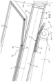
figures 8 and 9 not described in detail for sake of brevity. - In view of the foregoing, the advantages of the
work vehicle 1 according to the invention are apparent. - The
end stop mechanism 41 allows to protect thework vehicle 1 from damages, thus also increasing safety, by cooperating with each of thefirst arm 21, thesecond arm 22 and thetool 23. - Moreover, the load capacity pushing is increased. Indeed, in known systems without the end stop, the pushing load capacity, when pushing material, is lower, because the cylinder will have overload and is pushed back. Conversely, thanks to the present invention, the pushing capacity is higher since the frame is in contact with the end stop by overload instead of cylinders as in the prior art.
- In particular, the
end stop mechanism 41 is rotatably connected to theloader connection frame 11, is slidably carried by thefirst arm 21 and cooperates in contact with thesecond arm 22, in particular when theend stop mechanism 41 is in the second configuration. - In other words, the
end stop mechanism 41 rotatably cooperates with theloader connection frame 11, slidably cooperates with thefirst arm 21 and cooperates in contact with thesecond arm 22, in particular when theend stop mechanism 41 is in the second configuration. - It is clear that modifications can be made to the described
work vehicle 1 which do not extend beyond the scope of protection defined by the claims. - For example, the shape of the components may be different from that described or the loading device may be a rear loading device.
- Furthermore, the
end stop mechanism 41 may be coupled to thesecond arm 22 and configured to cooperate in contact with theloader connection frame 11. - Moreover,
stricter element 52 can be also configured differently from a welded tube, i.e. being a mold tube or a edged shape or a welded shape. Similarlyrod 51 can have a different shape or cross-section.
Claims (15)
- Work vehicle comprising a loader connection frame (11) and a loading device (12) connected thereto, wherein the loading device (12) comprises a first arm (21) rotatably connected to the loader connection frame (11), a second arm (22) rotatably connected to the first arm (21), and a tool (23) rotatably connected the second arm (22),
wherein the work vehicle (1) comprises an end stop mechanism (41) configured to cooperate with each of the loader connection frame (11), the first arm (21) and the second arm (22) . - Work vehicle as claimed in claim 1, wherein the end stop mechanism (41) is carried by the first arm (21).
- Work vehicle as claimed in claim 1 or 2, wherein the end stop mechanism (41) is slidable with respect to the first arm (21).
- Work vehicle as claimed in any of the preceding claims, wherein the end stop mechanism (41) is rotatably connected to the loader connection frame (11) and configured to assume a first configuration, wherein the end stop mechanism (41) is not in contact with the second arm (22), and a second configuration, wherein the end stop mechanism (41) is in contact with the second arm (22).
- Work vehicle as claimed in claim 4, wherein the end stop mechanism (41) comprises a rod (51) having a first end (51a) rotatably connected to the loader connection frame (11) and a second end (51b) configured to cooperate in contact with the second arm (22) when the end stop mechanism (41) is in the second configuration.
- Work vehicle as claimed in claim 5, wherein the second arm (22) comprises a striker element (52) configured to cooperate in contact with the second end (51b) of the rod (51) when the end stop mechanism (41) is in the second configuration.
- Work vehicle as claimed in claim 5 or 6, wherein the first arm (21) comprises a first flanged portion (61), the rod (51) being slidably coupled to the first flanged portion (61).
- Work vehicle as claimed in claim 7, wherein the first arm (21) comprises a second flanged portion (62), the rod (51) being slidably coupled to the second flanged portion (62), the rod (51) being interposed between the first flanged portion (61) and the second flanged portion (62).
- Work vehicle as claimed in claim 8, wherein the rod (51) extends along a rod axis (R) and at least sections (61', 62') of the first flanged portion (61) and the second flanged portion (62) extend parallel to the rod axis (R).
- Work vehicle as claimed in claim 8 or 9, wherein the first flanged portion (61) and the second flanged portion (62) have respective surfaces (91, 92) configured to cooperate in contact with the rod (51) and made of an anti-friction material.
- Work vehicle as claimed in any of the preceding claims, comprising a first actuator (31) configured to actuate the first arm (21), a second actuator (32) configured to actuate the second arm (22), and a third actuator (33) configured to actuate the tool (23).
- Work vehicle as claimed in claim 11, wherein the first actuator (31) is configured to cause rotation of the first arm (21) about a first axis (A1), the second actuator (32) is configured to cause rotation of the second arm (22) about a second axis (A2), and the third actuator (33) is configured to cause rotation of the tool (23) about a third axis (A3), wherein the first axis (A1), the second axis (A2) and the third axis (A3) are parallel to one another.
- Work vehicle as claimed in claim 12, comprising an electronic control unit configured to control the rotation of the first arm (21) about the first axis (A1) by acting on the first actuator (31), the rotation of the second arm (22) about the second axis (A2) by acting on the second actuator (32) and the rotation of the tool (23) about the third axis (A3) by acting on the third actuator (33) so that the tool (23) moves along a predetermined trajectory, the electronic control unit being configured to calculate the rotations of the first arm (21), the second arm (22) and the tool (23) via inverse kinematics algorithms.
- Work vehicle as claimed in claim 13, wherein the work vehicle is on a plane (P) and the predetermined trajectory is orthogonal to said plane (P).
- Work vehicle as claimed in any of claims 11 to 14, wherein:the first arm (21) has a first end portion (21a) rotatably connected to the loader connection frame (11),the second arm (22) has a first end portion (22a) rotatably connected to a second end portion (21b) of the first arm (21),the tool (23) has a connecting portion (23a) rotatably connected to a second end portion (22b) of the second arm (22),the first actuator (31) is a first hydraulic cylinder having a first end (31a) rotatably connected to the loader connection frame (11) and a second end (31b) rotatably connected to an appendage (34) extending from the second end portion (21b) of the first arm (21),the second actuator (32) is a second hydraulic cylinder having a first end (32a) rotatably connected to the appendage (34) and a second end (32b) rotatably connected to the second end portion (22b) of the second arm (22),the third actuator (33) is a third hydraulic cylinder having a first end (33a) rotatably connected to the first end portion (22a) of the second arm (22) and a second end (33b) rotatably connected to the tool (23).
Applications Claiming Priority (1)
| Application Number | Priority Date | Filing Date | Title |
|---|---|---|---|
| IT102023000015045A IT202300015045A1 (en) | 2023-07-18 | 2023-07-18 | IMPROVED LIMIT SWITCH MECHANISM FOR A WORK VEHICLE |
Publications (1)
| Publication Number | Publication Date |
|---|---|
| EP4495329A1 true EP4495329A1 (en) | 2025-01-22 |
Family
ID=88146619
Family Applications (1)
| Application Number | Title | Priority Date | Filing Date |
|---|---|---|---|
| EP24189058.1A Pending EP4495329A1 (en) | 2023-07-18 | 2024-07-17 | Improved end stop mechanism for a work vehicle |
Country Status (2)
| Country | Link |
|---|---|
| EP (1) | EP4495329A1 (en) |
| IT (1) | IT202300015045A1 (en) |
Citations (3)
| Publication number | Priority date | Publication date | Assignee | Title |
|---|---|---|---|---|
| SU613020A1 (en) * | 1976-01-05 | 1978-06-30 | Сибирский Автомобильно-Дорожный Институт Им.Куйбышева | Working equipment of single-bucket front-end loader |
| IT201900005800A1 (en) | 2019-04-15 | 2020-10-15 | Cnh Ind Italia Spa | INDUSTRIAL VEHICLE EQUIPPED WITH A FRONT EQUIPMENT |
| CN214194693U (en) * | 2020-12-17 | 2021-09-14 | 山推工程机械股份有限公司 | Pushing and installing machine |
-
2023
- 2023-07-18 IT IT102023000015045A patent/IT202300015045A1/en unknown
-
2024
- 2024-07-17 EP EP24189058.1A patent/EP4495329A1/en active Pending
Patent Citations (4)
| Publication number | Priority date | Publication date | Assignee | Title |
|---|---|---|---|---|
| SU613020A1 (en) * | 1976-01-05 | 1978-06-30 | Сибирский Автомобильно-Дорожный Институт Им.Куйбышева | Working equipment of single-bucket front-end loader |
| IT201900005800A1 (en) | 2019-04-15 | 2020-10-15 | Cnh Ind Italia Spa | INDUSTRIAL VEHICLE EQUIPPED WITH A FRONT EQUIPMENT |
| EP3725954A1 (en) * | 2019-04-15 | 2020-10-21 | CNH Industrial Italia S.p.A. | Industrial vehicle provided with a front tool |
| CN214194693U (en) * | 2020-12-17 | 2021-09-14 | 山推工程机械股份有限公司 | Pushing and installing machine |
Also Published As
| Publication number | Publication date |
|---|---|
| IT202300015045A1 (en) | 2025-01-18 |
Similar Documents
| Publication | Publication Date | Title |
|---|---|---|
| EP3051032B1 (en) | Wheel loader with lifting arrangement | |
| US9017005B2 (en) | Skid steer loader lift linkage assembly | |
| EP3051031B1 (en) | Wheel loader with a lifting arrangement | |
| US10981763B2 (en) | Work tool leveling system | |
| EP0564501A1 (en) | A linkage arrangement for a multi-purpose vehicle. | |
| JP2004516177A5 (en) | ||
| US10323387B2 (en) | Height compensating loader implement tool level indicator | |
| EP3469219B1 (en) | Improved arrangement and method for operating a hydraulic cylinder | |
| AU2019229362A1 (en) | Telehandler boom extension monitoring system | |
| CN110847263B (en) | Work vehicle with constant speed implement actuation | |
| US20200071905A1 (en) | Work vehicle including loader work device | |
| CN112832308B (en) | Electro-hydraulic implement control system and method | |
| US20200370269A1 (en) | Vertical lifting arrangement for construction machine | |
| US12114614B2 (en) | Gripper | |
| US20200393235A1 (en) | Rotational angle sensor holding system | |
| IT202300015045A1 (en) | IMPROVED LIMIT SWITCH MECHANISM FOR A WORK VEHICLE | |
| EP4389991A1 (en) | Swivel work machine | |
| US11105065B2 (en) | Lift arm leveling system | |
| CN217869877U (en) | Self-propelled road milling machine | |
| EP4563446A1 (en) | Multipurpose vehicle and multipurpose vehicular system | |
| US20120051878A1 (en) | Load Arm Arrangement For A Skid-Steer Loader | |
| AU2021277679B2 (en) | Work machine with automatic pitch control of implement | |
| US4343588A (en) | Kickout bucket positioner | |
| TR2022019982U5 (en) | TELESCOPIC FORKLIFT HYDRAULIC DIRECTIONAL CONTROL VALVE ASSEMBLY | |
| DD149792A1 (en) | DEVICE FOR LIMITING THE LOAD TORQUE, ESPECIALLY OF BOOMING CRANES |
Legal Events
| Date | Code | Title | Description |
|---|---|---|---|
| PUAI | Public reference made under article 153(3) epc to a published international application that has entered the european phase |
Free format text: ORIGINAL CODE: 0009012 |
|
| STAA | Information on the status of an ep patent application or granted ep patent |
Free format text: STATUS: THE APPLICATION HAS BEEN PUBLISHED |
|
| AK | Designated contracting states |
Kind code of ref document: A1 Designated state(s): AL AT BE BG CH CY CZ DE DK EE ES FI FR GB GR HR HU IE IS IT LI LT LU LV MC ME MK MT NL NO PL PT RO RS SE SI SK SM TR |
|
| STAA | Information on the status of an ep patent application or granted ep patent |
Free format text: STATUS: REQUEST FOR EXAMINATION WAS MADE |
|
| 17P | Request for examination filed |
Effective date: 20250722 |
|
| GRAP | Despatch of communication of intention to grant a patent |
Free format text: ORIGINAL CODE: EPIDOSNIGR1 |
|
| STAA | Information on the status of an ep patent application or granted ep patent |
Free format text: STATUS: GRANT OF PATENT IS INTENDED |
|
| INTG | Intention to grant announced |
Effective date: 20260420 |
|
| GRAS | Grant fee paid |
Free format text: ORIGINAL CODE: EPIDOSNIGR3 |
|
| GRAA | (expected) grant |
Free format text: ORIGINAL CODE: 0009210 |
|
| STAA | Information on the status of an ep patent application or granted ep patent |
Free format text: STATUS: THE PATENT HAS BEEN GRANTED |