EP4495327A1 - Positioning device for orienting at least one post-tensioning element in a concrete foundation - Google Patents
Positioning device for orienting at least one post-tensioning element in a concrete foundation Download PDFInfo
- Publication number
- EP4495327A1 EP4495327A1 EP23382753.4A EP23382753A EP4495327A1 EP 4495327 A1 EP4495327 A1 EP 4495327A1 EP 23382753 A EP23382753 A EP 23382753A EP 4495327 A1 EP4495327 A1 EP 4495327A1
- Authority
- EP
- European Patent Office
- Prior art keywords
- vertical
- post
- tensioning element
- hole
- foundation
- Prior art date
- Legal status (The legal status is an assumption and is not a legal conclusion. Google has not performed a legal analysis and makes no representation as to the accuracy of the status listed.)
- Pending
Links
Images


Classifications
-
- E—FIXED CONSTRUCTIONS
- E04—BUILDING
- E04G—SCAFFOLDING; FORMS; SHUTTERING; BUILDING IMPLEMENTS OR AIDS, OR THEIR USE; HANDLING BUILDING MATERIALS ON THE SITE; REPAIRING, BREAKING-UP OR OTHER WORK ON EXISTING BUILDINGS
- E04G21/00—Preparing, conveying, or working-up building materials or building elements in situ; Other devices or measures for constructional work
- E04G21/14—Conveying or assembling building elements
- E04G21/16—Tools or apparatus
- E04G21/18—Adjusting tools; Templates
- E04G21/1841—Means for positioning building parts or elements
- E04G21/185—Means for positioning building parts or elements for anchoring elements or elements to be incorporated in the structure
-
- E—FIXED CONSTRUCTIONS
- E02—HYDRAULIC ENGINEERING; FOUNDATIONS; SOIL SHIFTING
- E02D—FOUNDATIONS; EXCAVATIONS; EMBANKMENTS; UNDERGROUND OR UNDERWATER STRUCTURES
- E02D27/00—Foundations as substructures
- E02D27/32—Foundations for special purposes
- E02D27/42—Foundations for poles, masts or chimneys
- E02D27/425—Foundations for poles, masts or chimneys specially adapted for wind motors masts
-
- E—FIXED CONSTRUCTIONS
- E04—BUILDING
- E04C—STRUCTURAL ELEMENTS; BUILDING MATERIALS
- E04C5/00—Reinforcing elements, e.g. for concrete; Auxiliary elements therefor
- E04C5/08—Members specially adapted to be used in prestressed constructions
- E04C5/12—Anchoring devices
- E04C5/122—Anchoring devices the tensile members are anchored by wedge-action
-
- E—FIXED CONSTRUCTIONS
- E04—BUILDING
- E04G—SCAFFOLDING; FORMS; SHUTTERING; BUILDING IMPLEMENTS OR AIDS, OR THEIR USE; HANDLING BUILDING MATERIALS ON THE SITE; REPAIRING, BREAKING-UP OR OTHER WORK ON EXISTING BUILDINGS
- E04G21/00—Preparing, conveying, or working-up building materials or building elements in situ; Other devices or measures for constructional work
- E04G21/12—Mounting of reinforcing inserts; Prestressing
Definitions
- the object of the invention relates to a positioning device for orienting at least one post-tensioning element in a concrete foundation.
- the invention also relates to a positioning system for orienting a post-tensioning element in a concrete foundation, a concrete foundation of a tower of a wind turbine, a wind turbine, and a method of manufacturing a wind turbine.
- Wind turbines comprise basically a tower, a nacelle that houses the drive train and the electric generator, and a rotor comprising usually at least two blades.
- the tower supports the rotor and the nacelle and transmits the loads to the foundation.
- the foundation is in charge of transferring the loads from the tower to the ground.
- foundations can be designed differently and therefore be classified into shallow, half-deep and deep.
- foundations can be shaped differently although frustoconical with a circular, hexagonal or even octagonal shape are the most common. They can also be solid or hollow (annular), being the difference between them that the latter ones comprise a central hollow in a zone where foundation materials are not necessary for load transmission. The use of materials for its construction, namely concrete and steel, is therefore reduced in hollow foundations with regards to solid ones.
- All these foundations are suitable for wind turbine towers made of steel, concrete, or both (hybrid towers).
- the towers comprising concrete sections usually have some post-tensioning elements whose ends are fastened to the foundation in order to ensure that the concrete is under compression stresses during the most of the wind turbine lifetime. That is, in order to avoid undesirable tension stresses in the structure that would lead to excessive cracks in concrete and fatigue in reinforcements.
- connection of the ends of the post-tensioning element to the foundation can differ depending on the type of foundation, but the connection is always difficult due to the post-tensioning inclination due to the conical towers commonly used in these wind turbines.
- the positioning device for orienting at least one post-tensioning element in a concrete foundation solves the drawbacks of the connection systems known in the state-of-the-art.
- the invention relates to a positioning device for orienting at least one post-tensioning element in a concrete foundation
- the positioning device so configured allows to dispose the post-tensioning element in a vertical through-hole of the foundation even if the post-tensioning element is disposed in an inclined disposition across the foundation.
- the diameter of the cylindrical vertical wall is between 1,5 and 2 times the diameter of the post-tensioning element.
- the tolerance for the introduction of the post-tensioning element in the vertical through-hole of the foundation is increased, avoiding damages on the post-tensioning element with the walls of the vertical through-hole.
- the height of the cylindrical vertical wall is greater than the height of the at least one vertical through-hole. In this way, the extraction of the position device from the foundation is easier since it is possible to pull from the vertical wall once the concrete of the foundation is at least partially cured.
- the invention also relates to a positioning system for orienting a post-tensioning element in a concrete foundation comprising the positioning device described above and at least one template formwork configured to allocate the positioning device in a first position.
- the at least one template formwork comprises a clamp assembly configured to clamp the positioning device in the first position.
- the positioning system further comprising a bearing plate configured to attach the lower end of the post-tensioning element to the inner upper surface of the foundation.
- the bearing plate helps to anchor the post-tensioning element to the foundation and also helps to incline the post-tensioning element with respect to the foundation through the at least one vertical through-hole.
- the invention also relates to a concrete foundation of a tower of a wind turbine comprising:
- the diameter of the at least one vertical through-hole is between 1,5 and 2 times the diameter of the post-tensioning element.
- the foundation further comprises at least one reinforcement surrounding, at least partially, the at least one vertical through-hole.
- the post-tensioning element is disposed forming an angle between 1o and 1,8o with the vertical axis of the at least one vertical through-hole.
- the post-tensioning element is disposed forming an angle between 1,2o and 1,6o with the vertical axis of the at least one vertical through-hole.
- the invention also relates to a wind turbine comprising the foundation described above, further comprising a tower comprising at least a tower section and at least one post-tensioning element.
- the tower is a full concrete tower or a hybrid steel-concrete tower.
- the invention also relates to a method of manufacturing the wind turbine described above comprising:
- the step of casting the at least one vertical through-hole in the foundation by means of the positioning device comprises a step of positioning at least one template formwork configured to allocate the positioning device in a first position.
- the following is a detailed description of the positioning device (1) for orienting at least one post-tensioning element (10) in a concrete foundation (20),
- the diameter (D2) of the cylindrical vertical wall (2) is between 1,5 and 2 times the diameter (D3) of the post-tensioning element (10), more preferably between 1,65 and 1,85 times the diameter (D3) of the post-tensioning element (10).
- the height (H2) of the cylindrical vertical wall (2) is greater than the height (H1) of the at least one vertical through-hole (21),so facilitating the subsequent removal of the positioning device (10) from the foundation (20).
- the positioning system for orienting a post-tensioning element (10) in a concrete foundation (20) comprising the positioning device (1) described above and at least one template formwork (30) configured to allocate the positioning device (1) in a first position (P1), is shown in Figure 1 .
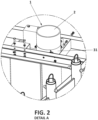
- the at least one template formwork (30) comprises a clamp assembly (31) configured to clamp the positioning device (1) in the first position (P1), a shown in Figure 2 .
- the positioning system further comprises a bearing plate (15) configured to attach the lower end (12) of the post-tensioning element (10) to the inner upper surface (23) of the foundation (20).
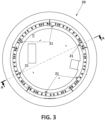
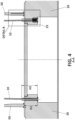
- the concrete foundation (20) of a tower (100) of a wind turbine show in Figures 3 to 5 comprises:
- the diameter (D1) of the at least one vertical through-hole (21) is between 1,5 and 2 times the diameter (D3) of the post-tensioning element (10).
- the foundation (20) further comprises at least one reinforcement (24, 25) surrounding, at least partially, the at least one vertical through-hole (21).
- the foundation (20) comprises at least one reinforcement (24, 25) surrounding, at least partially, the at least one vertical through-hole (21).
- the at least one reinforcement (24, 25) comprises a spiral reinforcement (24) surrounding, at least partially, the cylindrical vertical wall (2) of the at least one positioning device (1) and/or a plurality of linear reinforcements (25) encircling the cylindrical vertical wall (2) of the at least one positioning device (1) in parallel directions two by two.
- the post-tensioning element (10) is disposed forming an angle between 1o and 1,8o with the vertical axis (22) of the at least one vertical through-hole (21), preferably forming an angle between 1,2o and 1,6o with the vertical axis (22) of the at least one vertical through-hole (21).
- the wind turbine comprising the foundation (20) described above and a tower (100) comprising at least a tower section (50) and at least one post-tensioning element (10) is partially shown in Figure 5 .
- the tower (100) may be a full concrete tower or a steel-concrete tower (hybrid tower).
Landscapes
- Engineering & Computer Science (AREA)
- Architecture (AREA)
- Civil Engineering (AREA)
- Structural Engineering (AREA)
- Mechanical Engineering (AREA)
- Life Sciences & Earth Sciences (AREA)
- General Life Sciences & Earth Sciences (AREA)
- Mining & Mineral Resources (AREA)
- Paleontology (AREA)
- General Engineering & Computer Science (AREA)
- Wind Motors (AREA)
- Foundations (AREA)
Abstract
A positioning device for orienting at least one post-tensioning element in a concrete foundation, to a positioning system for orienting a post-tensioning element in a concrete foundation, to a concrete foundation of a tower of a wind turbine, to a wind turbine, and to a method of manufacturing a wind turbine.
Description
- The object of the invention relates to a positioning device for orienting at least one post-tensioning element in a concrete foundation.
- The invention also relates to a positioning system for orienting a post-tensioning element in a concrete foundation, a concrete foundation of a tower of a wind turbine, a wind turbine, and a method of manufacturing a wind turbine.
- The goal of wind energy consists of generating electricity from wind through wind turbines with maximum efficiency and minimum cost. Wind turbines comprise basically a tower, a nacelle that houses the drive train and the electric generator, and a rotor comprising usually at least two blades.
- The tower supports the rotor and the nacelle and transmits the loads to the foundation. In turn, the foundation is in charge of transferring the loads from the tower to the ground.
- Depending on the kind of soil (according to its bearing capacity, mainly) foundations can be designed differently and therefore be classified into shallow, half-deep and deep.
- In terms of geometry, foundations can be shaped differently although frustoconical with a circular, hexagonal or even octagonal shape are the most common. They can also be solid or hollow (annular), being the difference between them that the latter ones comprise a central hollow in a zone where foundation materials are not necessary for load transmission. The use of materials for its construction, namely concrete and steel, is therefore reduced in hollow foundations with regards to solid ones.
- All these foundations are suitable for wind turbine towers made of steel, concrete, or both (hybrid towers). The towers comprising concrete sections usually have some post-tensioning elements whose ends are fastened to the foundation in order to ensure that the concrete is under compression stresses during the most of the wind turbine lifetime. That is, in order to avoid undesirable tension stresses in the structure that would lead to excessive cracks in concrete and fatigue in reinforcements.
- The connection of the ends of the post-tensioning element to the foundation can differ depending on the type of foundation, but the connection is always difficult due to the post-tensioning inclination due to the conical towers commonly used in these wind turbines.
- The positioning device for orienting at least one post-tensioning element in a concrete foundation solves the drawbacks of the connection systems known in the state-of-the-art.
- The invention relates to a positioning device for orienting at least one post-tensioning element in a concrete foundation,
- wherein the post-tensioning element comprises at least a diameter and a lower end;
- wherein the foundation comprises:
- at least one vertical through-hole comprising a vertical axis, a diameter, and a height, and being configured to allow the passage of at least the post-tensioning element;
- an inner upper surface configured to attach the lower end of the post-tensioning element;
- wherein the positioning device is configured, in use, to cast the at least one vertical through-hole in the foundation; and
- wherein the positioning device comprises a cylindrical vertical wall comprising a height, and a diameter being configured to cast the diameter of the at least one vertical through-hole which allows the passage of the at least one post-tensioning element in an inclined disposition with regard to the vertical axis of the at least one vertical through-hole.
- The positioning device so configured allows to dispose the post-tensioning element in a vertical through-hole of the foundation even if the post-tensioning element is disposed in an inclined disposition across the foundation.
- Optionally, the diameter of the cylindrical vertical wall is between 1,5 and 2 times the diameter of the post-tensioning element.
- So, the tolerance for the introduction of the post-tensioning element in the vertical through-hole of the foundation is increased, avoiding damages on the post-tensioning element with the walls of the vertical through-hole.
- Optionally, the height of the cylindrical vertical wall is greater than the height of the at least one vertical through-hole. In this way, the extraction of the position device from the foundation is easier since it is possible to pull from the vertical wall once the concrete of the foundation is at least partially cured.
- The invention also relates to a positioning system for orienting a post-tensioning element in a concrete foundation comprising the positioning device described above and at least one template formwork configured to allocate the positioning device in a first position.
- Optionally, the at least one template formwork comprises a clamp assembly configured to clamp the positioning device in the first position.
- Optionally, the positioning system further comprising a bearing plate configured to attach the lower end of the post-tensioning element to the inner upper surface of the foundation.
- Thus, the bearing plate helps to anchor the post-tensioning element to the foundation and also helps to incline the post-tensioning element with respect to the foundation through the at least one vertical through-hole.
- The invention also relates to a concrete foundation of a tower of a wind turbine comprising:
- at least one vertical through-hole conformed by the positioning device described above, the at least one vertical through-hole comprising a vertical axis, a diameter, and a height, and being configured to allow the passage of at least a post-tensioning element;
- an inner upper surface configured to attach a lower end of the post-tensioning element;
- Optionally, the diameter of the at least one vertical through-hole is between 1,5 and 2 times the diameter of the post-tensioning element.
- Optionally, the foundation further comprises at least one reinforcement surrounding, at least partially, the at least one vertical through-hole.
- Optionally, in use, the post-tensioning element is disposed forming an angle between 1º and 1,8º with the vertical axis of the at least one vertical through-hole.
- Optionally, in use, the post-tensioning element is disposed forming an angle between 1,2º and 1,6º with the vertical axis of the at least one vertical through-hole.
- The invention also relates to a wind turbine comprising the foundation described above, further comprising a tower comprising at least a tower section and at least one post-tensioning element. Preferably, the tower is a full concrete tower or a hybrid steel-concrete tower.
- The invention also relates to a method of manufacturing the wind turbine described above comprising:
- a step of orienting a post-tensioning element in the concrete foundation which in turn comprises:
- a step of casting the at least one vertical through-hole in the foundation by means of the positioning device;
- a step of passing the post-tensioning element through the at least one vertical through-hole in an inclined disposition with regard to the vertical axis of the at least one vertical through-hole.
- Optionally, the step of casting the at least one vertical through-hole in the foundation by means of the positioning device comprises a step of positioning at least one template formwork configured to allocate the positioning device in a first position.
- To complement the description being made and for the sake of a better understanding of the characteristics of the invention according to a preferred practical embodiment thereof, attached as an integral part of said description are a set of drawings wherein, for the purpose of illustration and not limiting the scope of the invention, the following is shown:
-
Figure 1 shows a perspective view of the at least one template formwork configured to allocate a plurality of positioning devices each one in a first position. -
Figure 2 shows a detail A ofFigure 1 . -
Figure 3 shows a plan view of the foundation of the present invention together with a first concrete section disposed above the foundation. -
Figure 4 shows a section AA ofFigure 3 , wherein the reinforcements have not been represented in the left side. -
Figure 5 shows a detail B ofFigure 4 . - The following is a detailed description of the positioning device (1) for orienting at least one post-tensioning element (10) in a concrete foundation (20),
- wherein the post-tensioning element (10) comprises at least a diameter (D3) and a lower end (12);
- wherein the foundation (20) comprises:
- at least one vertical through-hole (21) comprising a vertical axis (22), a diameter (D1), and a height (H1), and being configured to allow the passage of at least the post-tensioning element (10);
- an inner upper surface (23) configured to attach the lower end (12) of the post-tensioning element (10);
- wherein the positioning device (1) is configured, in use, to cast the at least one vertical through-hole (21) in the foundation (20); and
- wherein the positioning device (1) comprises a cylindrical vertical wall (2) comprising a height (H2), and a diameter (D2) being configured to cast the diameter (D1) of the at least one vertical through-hole (21) which allows the passage of the at least one post-tensioning element (10) in an inclined disposition with regard to the vertical axis (22) of the at least one vertical through-hole (21).
- Preferably, the diameter (D2) of the cylindrical vertical wall (2) is between 1,5 and 2 times the diameter (D3) of the post-tensioning element (10), more preferably between 1,65 and 1,85 times the diameter (D3) of the post-tensioning element (10).
- As shown in
Figure 5 , the height (H2) of the cylindrical vertical wall (2) is greater than the height (H1) of the at least one vertical through-hole (21),so facilitating the subsequent removal of the positioning device (10) from the foundation (20). - The positioning system for orienting a post-tensioning element (10) in a concrete foundation (20) comprising the positioning device (1) described above and at least one template formwork (30) configured to allocate the positioning device (1) in a first position (P1), is shown in
Figure 1 . - In this embodiment, the at least one template formwork (30) comprises a clamp assembly (31) configured to clamp the positioning device (1) in the first position (P1), a shown in
Figure 2 . - The positioning system further comprises a bearing plate (15) configured to attach the lower end (12) of the post-tensioning element (10) to the inner upper surface (23) of the foundation (20).
- The concrete foundation (20) of a tower (100) of a wind turbine show in
Figures 3 to 5 comprises: - at least one vertical through-hole (21) conformed by the positioning device (1) of any of
claims 1 to 3, the at least one vertical through-hole (21) comprising a vertical axis (22), a diameter (D1), and a height (H1), and being configured to allow the passage of at least a post-tensioning element (10); - an inner upper surface (23) configured to attach a lower end (12) of the post-tensioning element (10);
- Preferably, in the foundation (20), the diameter (D1) of the at least one vertical through-hole (21) is between 1,5 and 2 times the diameter (D3) of the post-tensioning element (10).
- The foundation (20) further comprises at least one reinforcement (24, 25) surrounding, at least partially, the at least one vertical through-hole (21). In particular, in this embodiment, the foundation (20) comprises at least one reinforcement (24, 25) surrounding, at least partially, the at least one vertical through-hole (21). Preferably, the at least one reinforcement (24, 25) comprises a spiral reinforcement (24) surrounding, at least partially, the cylindrical vertical wall (2) of the at least one positioning device (1) and/or a plurality of linear reinforcements (25) encircling the cylindrical vertical wall (2) of the at least one positioning device (1) in parallel directions two by two.
- Once disposed in the at least one vertical through-hole (21) of the foundation (20), the post-tensioning element (10) is disposed forming an angle between 1º and 1,8º with the vertical axis (22) of the at least one vertical through-hole (21), preferably forming an angle between 1,2º and 1,6º with the vertical axis (22) of the at least one vertical through-hole (21).
- The wind turbine comprising the foundation (20) described above and a tower (100) comprising at least a tower section (50) and at least one post-tensioning element (10) is partially shown in
Figure 5 . The tower (100) may be a full concrete tower or a steel-concrete tower (hybrid tower).
Claims (14)
- Positioning device (1) for orienting at least one post-tensioning element (10) in a concrete foundation (20),wherein the post-tensioning element (10) comprises at least a diameter (D3) and a lower end (12);wherein the foundation (20) comprises:- at least one vertical through-hole (21) comprising a vertical axis (22), a diameter (D1), and a height (H1), and being configured to allow the passage of at least the post-tensioning element (10);- an inner upper surface (23) configured to attach the lower end (12) of the post-tensioning element (10);wherein the positioning device (1) is configured, in use, to cast the at least one vertical through-hole (21) in the foundation (20); andwherein the positioning device (1) comprises a cylindrical vertical wall (2) comprising a height (H2), and a diameter (D2) being configured to cast the diameter (D1) of the at least one vertical through-hole (21) which allows the passage of the at least one post-tensioning element (10) in an inclined disposition with regard to the vertical axis (22) of the at least one vertical through-hole (21).
- The positioning device (1) of any of claim 1, wherein the diameter (D2) of the cylindrical vertical wall (2) is between 1,5 and 2 times the diameter (D3) of the post-tensioning element (10).
- The positioning device (1) of any of preceding claims, wherein the height (H2) of the cylindrical vertical wall (2) is greater than the height (H1) of the at least one vertical through-hole (21).
- Positioning system for orienting a post-tensioning element (10) in a concrete foundation (20) comprising the positioning device (1) of any of previous claims and at least one template formwork (30) configured to allocate the positioning device (1) in a first position (P1).
- The positioning system of claim 4, wherein the at least one template formwork (30) comprises a clamp assembly (31) configured to clamp the positioning device (1) in the first position (P1).
- The positioning system of any of claims 4 or 5, further comprising a bearing plate (15) configured to attach the lower end (12) of the post-tensioning element (10) to the inner upper surface (23) of the foundation (20).
- Concrete foundation (20) of a tower (100) of a wind turbine comprising:- at least one vertical through-hole (21) conformed by the positioning device (1) of any of claims 1 to 3, the at least one vertical through-hole (21) comprising a vertical axis (22), a diameter (D1), and a height (H1), and being configured to allow the passage of at least a post-tensioning element (10);- an inner upper surface (23) configured to attach a lower end (12) of the post-tensioning element (10);wherein the at least one vertical through-hole (21) is configured to allow, in use, the passage of at least the post-tensioning element (10) in an inclined disposition with regard to the vertical axis (22) of the at least one vertical through-hole (21).
- The foundation of claim 7, wherein the diameter (D1) of the at least one vertical through-hole (21) is between 1,5 and 2 times the diameter (D3) of the post-tensioning element (10).
- The foundation of any of claims 7 or 8 further comprising at least one reinforcement (24, 25) surrounding, at least partially, the at least one vertical through-hole (21).
- The foundation of any of claims 7 to 9, wherein, in use, the post-tensioning element (10) is disposed forming an angle between 1º and 1,8º with the vertical axis (22) of the at least one vertical through-hole (21).
- The foundation of claim 10, wherein, in use, the post-tensioning element (10) is disposed forming an angle between 1,2º and 1,6º with the vertical axis (22) of the at least one vertical through-hole (21).
- Wind turbine comprising the foundation of any of claims 6 to 11, further comprising a tower (100) comprising at least a tower section (50) and at least one post-tensioning element (10).
- Method of manufacturing a wind turbine according to claim 12 comprising:- a step of orienting a post-tensioning element (10) in the concrete foundation (20) which in turn comprises:- a step of casting the at least one vertical through-hole (21) in the foundation (20) by means of the positioning device (1);- a step of passing the post-tensioning element (10) through the at least one vertical through-hole (21) in an inclined disposition with regard to the vertical axis (22) of the at least one vertical through-hole (21).
- The method of claim 13, wherein the step of casting the at least one vertical through-hole (21) in the foundation (20) by means of the positioning device (1) comprises a step of positioning at least one template formwork (30) configured to allocate the positioning device (1) in a first position (P1).
Priority Applications (4)
| Application Number | Priority Date | Filing Date | Title |
|---|---|---|---|
| EP23382753.4A EP4495327A1 (en) | 2023-07-21 | 2023-07-21 | Positioning device for orienting at least one post-tensioning element in a concrete foundation |
| CN202480057613.0A CN121794428A (en) | 2023-07-21 | 2024-07-16 | Positioning device for orienting at least one post-tensioning element in a concrete foundation. |
| EP24742954.1A EP4747454A1 (en) | 2023-07-21 | 2024-07-16 | Positioning device for orienting at least one post-tensioning element in a concrete foundation |
| PCT/EP2024/070109 WO2025021589A1 (en) | 2023-07-21 | 2024-07-16 | Positioning device for orienting at least one post-tensioning element in a concrete foundation |
Applications Claiming Priority (1)
| Application Number | Priority Date | Filing Date | Title |
|---|---|---|---|
| EP23382753.4A EP4495327A1 (en) | 2023-07-21 | 2023-07-21 | Positioning device for orienting at least one post-tensioning element in a concrete foundation |
Publications (1)
| Publication Number | Publication Date |
|---|---|
| EP4495327A1 true EP4495327A1 (en) | 2025-01-22 |
Family
ID=87429123
Family Applications (2)
| Application Number | Title | Priority Date | Filing Date |
|---|---|---|---|
| EP23382753.4A Pending EP4495327A1 (en) | 2023-07-21 | 2023-07-21 | Positioning device for orienting at least one post-tensioning element in a concrete foundation |
| EP24742954.1A Pending EP4747454A1 (en) | 2023-07-21 | 2024-07-16 | Positioning device for orienting at least one post-tensioning element in a concrete foundation |
Family Applications After (1)
| Application Number | Title | Priority Date | Filing Date |
|---|---|---|---|
| EP24742954.1A Pending EP4747454A1 (en) | 2023-07-21 | 2024-07-16 | Positioning device for orienting at least one post-tensioning element in a concrete foundation |
Country Status (3)
| Country | Link |
|---|---|
| EP (2) | EP4495327A1 (en) |
| CN (1) | CN121794428A (en) |
| WO (1) | WO2025021589A1 (en) |
Citations (6)
| Publication number | Priority date | Publication date | Assignee | Title |
|---|---|---|---|---|
| CH524037A (en) * | 1969-02-25 | 1972-06-15 | Oesterr Doka Schalung | Concrete formwork |
| DE102009010722A1 (en) * | 2009-02-27 | 2010-09-02 | Qualiplast Gmbh | Concrete wall formwork has formwork shell and supporting elements, where formwork halves are arranged on both sides of wall, and anchor rod is plugged in area of anchor holes through sleeve, where sleeve is provided with seal |
| EP2241699A2 (en) * | 2009-04-07 | 2010-10-20 | Thomas Friedrich | Anchor casing for anchoring pre-tensioned reinforcement elements |
| DE102010002108A1 (en) * | 2010-02-18 | 2011-08-18 | Peri GmbH, 89264 | Anchor system of a concrete wall formwork |
| DE102014012037A1 (en) * | 2014-08-16 | 2016-02-18 | Redima Ag | Anchoring device of a concrete wall formwork, formwork element and method for mounting an anchoring device |
| DE102019201395A1 (en) * | 2019-02-04 | 2020-08-06 | Hünnebeck GmbH | Wall formwork with sleeve for anchor holes, sleeve and cleaning process |
-
2023
- 2023-07-21 EP EP23382753.4A patent/EP4495327A1/en active Pending
-
2024
- 2024-07-16 WO PCT/EP2024/070109 patent/WO2025021589A1/en not_active Ceased
- 2024-07-16 CN CN202480057613.0A patent/CN121794428A/en active Pending
- 2024-07-16 EP EP24742954.1A patent/EP4747454A1/en active Pending
Patent Citations (6)
| Publication number | Priority date | Publication date | Assignee | Title |
|---|---|---|---|---|
| CH524037A (en) * | 1969-02-25 | 1972-06-15 | Oesterr Doka Schalung | Concrete formwork |
| DE102009010722A1 (en) * | 2009-02-27 | 2010-09-02 | Qualiplast Gmbh | Concrete wall formwork has formwork shell and supporting elements, where formwork halves are arranged on both sides of wall, and anchor rod is plugged in area of anchor holes through sleeve, where sleeve is provided with seal |
| EP2241699A2 (en) * | 2009-04-07 | 2010-10-20 | Thomas Friedrich | Anchor casing for anchoring pre-tensioned reinforcement elements |
| DE102010002108A1 (en) * | 2010-02-18 | 2011-08-18 | Peri GmbH, 89264 | Anchor system of a concrete wall formwork |
| DE102014012037A1 (en) * | 2014-08-16 | 2016-02-18 | Redima Ag | Anchoring device of a concrete wall formwork, formwork element and method for mounting an anchoring device |
| DE102019201395A1 (en) * | 2019-02-04 | 2020-08-06 | Hünnebeck GmbH | Wall formwork with sleeve for anchor holes, sleeve and cleaning process |
Also Published As
| Publication number | Publication date |
|---|---|
| CN121794428A (en) | 2026-04-03 |
| EP4747454A1 (en) | 2026-05-27 |
| WO2025021589A1 (en) | 2025-01-30 |
Similar Documents
| Publication | Publication Date | Title |
|---|---|---|
| EP2310595B1 (en) | Method for the assembly of a tower and tower | |
| EP1474579B2 (en) | Wind turbine | |
| EP2215320B1 (en) | Segmented concrete tower for wind power generators and method of erecting thereof | |
| EP2531674B1 (en) | A tower construction and a method for erecting the tower construction | |
| US9670909B2 (en) | Wind turbine foundation and wind turbine | |
| US11578698B2 (en) | Foundation for a windmill | |
| EP3247849B1 (en) | Wind turbine tower | |
| CN108138751B (en) | Tower segments for tethered wind turbine towers | |
| US11851902B2 (en) | Tower arrangement for a wind turbine, wind turbine comprising the tower arrangement and method for erecting a wind turbine | |
| KR20110092208A (en) | Wind turbines with monopole towers and monopole towers | |
| CA2998110C (en) | System and method for installing a tensioning tendon in a wind turbine tower | |
| EP2574772B1 (en) | Wind turbine tower | |
| US20160265514A1 (en) | Support device and methods for improving and constructing a support device | |
| WO2025021589A1 (en) | Positioning device for orienting at least one post-tensioning element in a concrete foundation | |
| EP4345297B1 (en) | Tower of a wind turbine | |
| WO2024068720A1 (en) | Concrete segment of a section of a tower of a wind turbine and adapter of a tower of a wind turbine tower | |
| CN113404642A (en) | Wind turbine | |
| RU2782228C2 (en) | Foundation for wind power plant | |
| EP2568165A2 (en) | Wind turbine, method for building a wind turbine and method for increasing the height of an existing wind turbine | |
| AU2023348084A1 (en) | Concrete segment of a section of a tower of a wind turbine and adapter of a tower of a wind turbine tower | |
| CA3269053A1 (en) | Concrete segment of a section of a tower of a wind turbine and adapter of a tower of a wind turbine tower |
Legal Events
| Date | Code | Title | Description |
|---|---|---|---|
| PUAI | Public reference made under article 153(3) epc to a published international application that has entered the european phase |
Free format text: ORIGINAL CODE: 0009012 |
|
| STAA | Information on the status of an ep patent application or granted ep patent |
Free format text: STATUS: THE APPLICATION HAS BEEN PUBLISHED |
|
| AK | Designated contracting states |
Kind code of ref document: A1 Designated state(s): AL AT BE BG CH CY CZ DE DK EE ES FI FR GB GR HR HU IE IS IT LI LT LU LV MC ME MK MT NL NO PL PT RO RS SE SI SK SM TR |
|
| STAA | Information on the status of an ep patent application or granted ep patent |
Free format text: STATUS: REQUEST FOR EXAMINATION WAS MADE |
|
| 17P | Request for examination filed |
Effective date: 20250715 |