EP4495315A1 - Dispensing device and laundry treatment apparatus - Google Patents
Dispensing device and laundry treatment apparatus Download PDFInfo
- Publication number
- EP4495315A1 EP4495315A1 EP23773665.7A EP23773665A EP4495315A1 EP 4495315 A1 EP4495315 A1 EP 4495315A1 EP 23773665 A EP23773665 A EP 23773665A EP 4495315 A1 EP4495315 A1 EP 4495315A1
- Authority
- EP
- European Patent Office
- Prior art keywords
- water
- chamber
- dispensing
- water inlet
- shell
- Prior art date
- Legal status (The legal status is an assumption and is not a legal conclusion. Google has not performed a legal analysis and makes no representation as to the accuracy of the status listed.)
- Pending
Links
Images





Classifications
-
- D—TEXTILES; PAPER
- D06—TREATMENT OF TEXTILES OR THE LIKE; LAUNDERING; FLEXIBLE MATERIALS NOT OTHERWISE PROVIDED FOR
- D06F—LAUNDERING, DRYING, IRONING, PRESSING OR FOLDING TEXTILE ARTICLES
- D06F39/00—Details of washing machines not specific to a single type of machines covered by groups D06F9/00 - D06F27/00
- D06F39/02—Devices for adding soap or other washing agents
- D06F39/022—Devices for adding soap or other washing agents in a liquid state
-
- D—TEXTILES; PAPER
- D06—TREATMENT OF TEXTILES OR THE LIKE; LAUNDERING; FLEXIBLE MATERIALS NOT OTHERWISE PROVIDED FOR
- D06F—LAUNDERING, DRYING, IRONING, PRESSING OR FOLDING TEXTILE ARTICLES
- D06F39/00—Details of washing machines not specific to a single type of machines covered by groups D06F9/00 - D06F27/00
- D06F39/02—Devices for adding soap or other washing agents
-
- D—TEXTILES; PAPER
- D06—TREATMENT OF TEXTILES OR THE LIKE; LAUNDERING; FLEXIBLE MATERIALS NOT OTHERWISE PROVIDED FOR
- D06F—LAUNDERING, DRYING, IRONING, PRESSING OR FOLDING TEXTILE ARTICLES
- D06F39/00—Details of washing machines not specific to a single type of machines covered by groups D06F9/00 - D06F27/00
- D06F39/08—Liquid supply or discharge arrangements
- D06F39/088—Liquid supply arrangements
-
- D—TEXTILES; PAPER
- D06—TREATMENT OF TEXTILES OR THE LIKE; LAUNDERING; FLEXIBLE MATERIALS NOT OTHERWISE PROVIDED FOR
- D06F—LAUNDERING, DRYING, IRONING, PRESSING OR FOLDING TEXTILE ARTICLES
- D06F35/00—Washing machines, apparatus, or methods not otherwise provided for
- D06F35/005—Methods for washing, rinsing or spin-drying
- D06F35/008—Methods for washing, rinsing or spin-drying for disinfecting the tub or the drum
Definitions
- the present disclosure relates to the technical field of laundry treatment apparatuses, and more particularly, to a dispensing device and a laundry treatment apparatus.
- a sterilization device is disposed on a pipeline between a water inlet valve and a washing tub of the washing machine, which not only leads to a complicated pipeline structure, increasing a risk of water leakage, but also occupies a space inside a workbench, which is not conducive to layout of an internal structure of the workbench.
- an objective of the present disclosure is to provide a dispensing device, which has a simple structure and a high space utilization rate.
- the present disclosure further provides a laundry treatment apparatus having the dispensing device as described above.
- a dispensing device comprises: a dispensing case defining a water inlet chamber and a dispensing chamber dispensing a detergent; and a sterilization assembly disposed in the water inlet chamber.
- the water inlet chamber and the dispensing chamber are in communication with each other.
- a sterilization water flow may be formed and is re-mixed with the detergent, i.e., release of sterilization substances and dilution and mixing of the detergent are realized successively through a one-way inflow of water with a simple structure and low cost.
- the detergent i.e., release of sterilization substances and dilution and mixing of the detergent are realized successively through a one-way inflow of water with a simple structure and low cost.
- bacteria breeding can be effectively inhibited, and stains can be removed, thereby ensuring cleanliness.
- a complicated structure of a water inlet pipeline is avoided, and a space of the dispensing case can be effectively utilized.
- the sterilization assembly is rotatably disposed in the water inlet chamber.
- the sterilization assembly is provided with a plurality of blades on an outer peripheral wall of the sterilization assembly.
- the plurality of blades is arranged at intervals in a circumferential direction of the outer peripheral wall of the sterilization assembly.
- the sterilization assembly comprises: a housing having a water passing chamber and a plurality of water passing holes; and sterilization particles disposed in the water passing chamber.
- the water passing chamber and the water inlet chamber are in communication with each other via the plurality of water passing holes
- the water passing chamber is provided with a lifting rib on a wall surface of the water passing chamber.
- the housing is a transparent member.
- the housing comprises: a rotation shell having an end with an opening; and a rotation cover disposed at the opening of the rotation shell.
- the water passing chamber is defined by the rotation cover and the rotation shell. Another end of the rotation shell and the rotation cover are respectively rotatably engaged with two opposite side walls of the water inlet chamber, and the plurality of the water passing holes is formed at the rotation shell and/or the rotation cover.
- the dispensing case defines a water inflow channel and a water outflow channel.
- the water inlet chamber and a water inlet are in communication with each other via the water inflow channel.
- the water inlet chamber and the dispensing chamber are in communication with each other via the water outflow channel.
- the dispensing case further defines a distribution chamber.
- the water outflow channel and the dispensing chamber are in communication with each other via the distribution chamber.
- the distribution chamber is located above the dispensing chamber, and the distribution chamber has a plurality of spray holes formed on a bottom wall of the distribution chamber. The distribution chamber and the dispensing chamber are in communication with each other via the plurality of spray holes.
- the distribution chamber and the dispensing chamber are equal in quantity and located in a one-to-one correspondence.
- the dispensing case comprises: an outer shell defining an accommodation chamber with a side opening; a water passage component disposed in the outer shell and defining the water inlet chamber; and a drawer adapted to be drawably disposed in the accommodation chamber through the opening.
- the water inlet is formed on the outer shell.
- the water inflow channel, the water outflow channel, and the distribution chamber are defined by the water passage component itself and/or are defined between the water passage component and the outer shell.
- the dispensing chamber is defined by the drawer.
- the water passage component comprises: a first water passage plate disposed in the outer shell; a second water passage plate connected to an upper end of the first water passage plate; and a water inlet shell disposed below the second water passage plate and connected to the first water passage plate.
- the water inflow channel and a part of the water outflow channel are defined between the first water passage plate and a side wall of the outer shell.
- the second water passage plate is disposed in the outer shell, and the distribution chamber is defined between the second water passage plate and a top wall of the outer shell.
- the water inlet shell defines the water inlet chamber.
- the water inlet shell further defines another part of the water outflow channel.
- the other part of the water outflow channel is located below the water inlet chamber.
- the water inlet shell comprises: a fixed shell having an end connected to the first water passage plate and another end with an opening; and an end cover removably disposed at the opening of the fixed shell.
- the water inlet chamber is defined between the end cover and the fixed shell.
- two ends of the sterilization assembly are respectively rotatably engaged with the end cover and a bottom wall of the fixed shell.
- the drawer has an avoidance hole positioned directly facing the end cover to expose the end cover.
- the end cover is a transparent member.
- the drawer has an avoidance portion for avoiding the water inlet shell.
- the dispensing chamber comprises a first dispensing chamber and a second dispensing chamber, wherein the second dispensing chamber is spaced apart from the first dispensing chamber.
- the avoidance portion is formed as an avoidance recess located between the first dispensing chamber and the second dispensing chamber.
- the avoidance recess has a liquid leakage hole formed on a bottom wall of the avoidance recess.
- a laundry treatment apparatus according to an embodiment of a second aspect of the present disclosure comprises the dispensing device as described according to the above embodiments.
- a dispensing device 100 and a laundry treatment apparatus according to the embodiments of the present disclosure are described below with reference to FIG. 1 to FIG. 14 .
- the dispensing device 100 includes a dispensing case 10 and a sterilization assembly 20.
- the dispensing case 10 defines a water inlet chamber 1230 and a dispensing chamber 130.
- the water inlet chamber 1230 and the dispensing chamber 130 are in communication with each other.
- the dispensing chamber 130 may be a dispensing chamber 130 configured to dispense a detergent, and the sterilization assembly 20 is disposed in the water inlet chamber 1230.
- a water inlet valve is opened, and water flows into the water inlet chamber 1230 of the dispensing device 100.
- the water flowing into the water inlet chamber 1230 may impact the sterilization assembly 20, enabling the water to have a sterilization function.
- the water with the sterilization function flows out of the water inlet chamber 1230 and then enters the dispensing chamber 130, and may be mixed with the detergent in the dispensing chamber 130, enabling the water to have sterilization, washing, and other functions for use in washing.
- a sterilization water flow may be formed and is re-mixed with the detergent, i.e., release of sterilization substances and dilution and mixing of the detergent are realized successively through a one-way inflow of water with a simple structure and low cost.
- the detergent i.e., release of sterilization substances and dilution and mixing of the detergent are realized successively through a one-way inflow of water with a simple structure and low cost.
- bacteria breeding can be effectively inhibited, stains can be removed, thereby ensuring cleanliness.
- a complicated structure of a water inlet pipeline can be avoided, and a space of the dispensing case can be effectively utilized.
- the sterilization assembly 20 is rotatably disposed in the water inlet chamber 1230, which allows the water to be in full contact with the sterilization assembly 20, greatly enhancing sterilization and bacteriostatic functions of the water.
- the sterilization assembly 20 is provided with a plurality of blades 2112 on an outer peripheral wall of the sterilization assembly 20.
- the plurality of blades 2112 is arranged at intervals in a circumferential direction of the outer peripheral wall of the sterilization assembly 20.
- the water flowing into the water inlet chamber 1230 impacts the plurality of blades 2112, which drives the sterilization assembly 20 to rotate, bringing the water into full contact with the sterilization assembly 20.
- the sterilization assembly 20 includes a housing 21 and sterilization particles 22.
- the housing 21 has a water passing chamber 2101 and a plurality of water passing holes 2102.
- the water passing chamber 2101 and the water inlet chamber 1230 may be in communication with each other via the plurality of water passing holes 2102.
- the sterilization particles 22 are disposed in the water passing chamber 2101.
- the water flowing into the water inlet chamber 1230 may flow into the water passing chamber 2101 through the plurality of water passing holes 2102, and the water flowing into the water passing chamber 2101 is in full contact with the sterilization particles 22, enabling the water to have the sterilization function.
- the sterilization water in the water passing chamber 2101 may also flow to the water inlet chamber 1230 through the plurality of water passing holes 2102, then flow into the dispensing chamber 130, and may be mixed with the detergent in the dispensing chamber 130 for use in washing.
- the housing 21 is provided with a plurality of blades 2112 on an outer peripheral wall of the housing 21.
- the plurality of blades 2112 is arranged at intervals in a circumferential direction of the outer peripheral wall of the housing 21.
- the water flowing into the water inlet chamber 1230 impacts the blades 2112 on the housing 21, thereby driving the housing 21 to rotate.
- the sterilization particles 22 in the water passing chamber 2101 may be driven to move and rub against each other, which allows solid sterilization particles 22 to be quickly released and to be fully mixed with the water, enabling the water to have the sterilization and bacteriostatic functions.
- the water passing chamber 2101 is provided with a lifting rib 2111 on a wall surface of the water passing chamber 2101.
- one lifting rib 2111 may be provided, and the lifting rib 2111 extends in an axial direction of the housing 21.
- the lifting rib 2111 may lift the sterilization particles 22 as moving upwards.
- the sterilization particles 22 fall under an action of gravity, causing impact and friction with the housing 21. In this way, the solid sterilization particles 22 are quickly released and fully mixed with the water, enabling the water to have the sterilization and bacteriostatic functions.
- a plurality of lifting ribs 2111 may be provided, and the plurality of lifting ribs 2111 is arranged at intervals in the circumferential direction of the peripheral wall of the housing 21. Each lifting rib 2111 extends in the axial direction of the housing 21.
- the housing 21 is a transparent member. By providing the housing 21 as the transparent member, visibility of the sterilization function is improved. A user may not only observe rolling states of the sterilization particles 22 through the housing 21 and add the sterilization particles 22 timely as needed, but may also form an intuitive feeling of the sterilization function, to improve user's trust and user experience.
- the dispensing device 100 further includes a light-emitting member (not shown), which may irradiate an interior of the housing 21, providing a more directly observable sterilization.
- the housing 21 includes a rotation shell 211 and a rotation cover 212.
- the rotation shell 211 has two ends, with one end having an opening.
- the rotation cover 211 is disposed at the opening of the rotation shell 211 to close the opening of the rotation shell 211.
- the water passing chamber 2101 is defined by the rotation cover 212 and the rotation shell 211, and the plurality of the water passing holes 2102 is formed at the rotation shell 211 and/or the rotation cover 212.
- the water flowing into the water inlet chamber 1230 impacts the plurality of blades 2112 on the housing 21, driving the housing 21 to rotate.
- the sterilization particles 22 may be driven to move and to impact and rub against the housing 21.
- the water in the water inlet chamber 1230 may enter the water passing chamber 2101 through the plurality of water passing holes 2102, and is fully mixed with the sterilization particles 22, enabling the water to have the sterilization and bacteriostatic functions.
- the water with the sterilization and bacteriostatic functions may flow into the water inlet chamber 1230 through the plurality of water passing holes 2102, and finally flow into the dispensing chamber 130 to be mixed with detergent for use in washing.
- the dispensing case 10 defines a water inflow channel 101.
- the water inlet chamber 1230 and a water inlet 111 are in communication with each other via the water inflow channel 101.
- the water may flow through the water inflow channel 101 from the water inlet 111, and then flow into the water inlet chamber 1230 to be fully mixed with the sterilization assembly 20.
- the water inlet 111 may be directly connected to the water inlet valve, allowing the water to be introduced into the water inlet chamber 1230.
- the water inlet 111 may also be connected to the water inlet valve through a pipeline.
- the water inlet chamber 1230 and the water inlet 111 may be conveniently in communication with each other. Moreover, a shape and structure of the water inflow channel 101 may be designed as needed, making it widely applicable.
- the dispensing case 10 also defines a water outflow channel 102.
- the water inlet chamber 1230 and the dispensing chamber 130 are in communication with each other via the water outflow channel 102.
- the water in the water inlet chamber 1230 enters the water passing chamber 2101 through the plurality of water passing holes 2102, and is fully mixed with the sterilization particles 22, enabling the water to have the sterilization and bacteriostatic functions.
- the water with the sterilization and bacteriostatic functions may flow to the water inlet chamber 1230 through the plurality of water passing holes 2102, and enter the dispensing chamber 130 through the water outflow channel 102 to be mixed with the detergent for use in washing.
- the water inlet chamber 1230 and the dispensing chamber 130 may be conveniently in communication with each other.
- a shape and structure of the water outflow channel 102 may be designed as needed, making it widely applicable.
- the dispensing case 10 further defines a distribution chamber 103.
- the water outflow channel 102 and the dispensing chamber 130 are in communication with each other via the distribution chamber 103.
- the distribution chamber 103 is located above the dispensing chamber 130.
- the distribution chamber 103 has a plurality of spray holes 1221 formed on a bottom wall of the distribution chamber 103.
- the distribution chamber 103 and the dispensing chamber 130 are in communication with each other via the plurality of spray holes 1221.
- the water having the sterilization function in the water inlet chamber 1230 may flow to the distribution chamber 103 through the water outflow channel 102. Since the distribution chamber 103 is located above the dispensing chamber 130, the water in the distribution chamber 103 may flow downwards to the dispensing chamber 130 through the spray holes 1221, to be mixed with the detergent in the dispensing chamber 130 for use in washing.
- the water having the sterilization function may be directed to a designated dispensing chamber 130 to be mixed with the detergent in the designated dispensing chamber 130. Therefore, the structure is simple and cost is lowered.
- the distribution chamber 103 and the dispensing chamber 130 are equal in quantity and located in a one-to-one correspondence.
- one distribution chamber 103 and one dispensing chamber 130 may be provided respectively.
- the distribution chamber 103 is disposed directly above the dispensing chamber 130, and the water flowing into the distribution chamber 103 may flow downwards through the plurality of spray holes 1221 under the action of gravity, thereby flowing into the dispensing chamber 130.
- the distribution chamber 103 includes a first distribution chamber 103 at a left side and a second distribution chamber 103 at a right side.
- the dispensing chamber 130 includes a first dispensing chamber 130 at a left side and a second dispensing chamber 103 at a right side.
- the first distribution chamber 103 is located directly above the first dispensing chamber 130, and the second distribution chamber 103 is located directly above the second dispensing chamber 130.
- the water in the water inlet chamber 1230 may flow into the first distribution chamber 103 through the water outflow channel 102, and then flow downwards to the first dispensing chamber 130 through a plurality of spray holes 1221 on a bottom wall of the first distribution chamber 103; or the water in the water inlet chamber 1230 may flow into the second distribution chamber 103 through the water outflow channel 102, and then flow downwards to the second dispensing chamber 130 through a plurality of spray holes 1221 on a bottom wall of the second distribution chamber 103.
- a plurality of (three or more) distribution chambers 103 and a plurality of (three or more) dispensing chambers 130 may be provided respectively.
- the arrangements of the plurality of distribution chambers 103 and the plurality of dispensing chambers 130 may be designed as desired, and details thereof are omitted herein.
- the dispensing case 10 includes an outer shell 11 defining an accommodation chamber 110 with an opening, and the water inlet 111 is formed on the outer shell 11, i.e., the outer shell 11 may be used as an appearance and structure member of the dispensing device 100, the opening of the outer shell 11 may be disposed at a front part of the outer shell 11, and the water inlet 111 may be disposed at a rear part of the outer shell 11.
- the dispensing case 10 further includes a water passage component 12.
- the water passage component 12 is disposed in the outer shell 11 and defines the water inlet chamber 1230.
- the water inflow channel 101, the water outflow channel 102, and the distribution chamber 103 may be defined by the water passage component 12 itself or be defined between the water passage component 12 and the outer shell 11.
- a part of each of the water inflow channel 101, the water outflow channel 102, and the distribution chamber 103 are defined by the water passage component 12 itself, and another part of each of the water inflow channel 101, the water outflow channel 102, and the distribution chamber 103 are defined between the water passage component 12 and the outer shell 11.
- This design is simple in structure and easy to be realized.
- the water passage component 12 and the outer shell 11 may be fixedly connected to each other by a fastener or may be connected to each other through a snap structure.
- the dispensing case 10 further includes a drawer 13 adapted to be drawably disposed in the accommodation chamber 110 through the opening.
- the dispensing chamber 130 is defined by the drawer 13.
- the water passage component 12 includes a first water passage plate 121 and a second water passage plate 122.
- the first water passage plate 121 is disposed in the outer shell 11.
- a part of the water outflow channel 102 and the water inflow channel 101 are defined between the first water passage plate 121 and a side wall of the outer shell 11.
- the second water passage plate 122 is connected to an upper end of the first water passage plate 121.
- the second water passage plate 122 is disposed in the outer shell 11, and the distribution chamber 103 is defined between the second water passage plate 122 and a top wall of the outer shell 11.
- the water inflow channel 101 includes a first water inflow channel 1011, a second water inflow channel 1012, and a third water inflow channel 1013.
- the first water inflow channel 1011 and the third water inflow channel 1013 are in communication with each other via the second water inflow channel 1012.
- the water outflow channel 102 includes a first water outflow channel 1021, a second water outflow channel 1022, and a third water outflow channel 1023.
- the first water outflow channel 1021 and the third water outflow channel 1023 are in communication with each other via the second water outflow channel 1022.
- the first water inflow channel 1011 is defined between the first water passage plate 121 and an inner surface of the side wall of the outer shell 11.
- the second water inflow channel 1012 is defined between the first water passage plate 121 and an inner surface of the top wall of the outer shell 11.
- the third water inflow channel 1012 is defined between the first water passage plate 121 and the second water passage plate 122.
- the first water outflow channel 1021 is defined between the first water passage plate 121 and the inner surface of the top wall of the outer shell 11, and the second water outflow channel 1022 is defined between the first water passage plate 121 and the inner surface of the side wall of the outer shell 11.
- the water passage component 12 further includes a water inlet shell 123.
- the water inlet shell 123 is disposed below the second water passage plate 122, and is connected to the first water passage plate 121.
- the water inlet shell 123 defines the water inlet chamber 1230.
- the water inlet shell 123 further defines another part of the water outflow channel 102, i.e., the third water outflow channel 1023.
- the third water outflow channel 1023 is located below the water inlet chamber 1230.
- the third water outflow channel 1023 extends in a length direction of the water inlet shell 123 (a front-rear direction as shown in FIG. 7 ), the water inlet chamber 1230 has a communication opening 1237 at a bottom wall of the water inlet chamber 1230, and the third water outflow channel 1023 is in communication with the communication opening 1237. In this way, the water in the water inlet chamber 1230 can enter the water outflow channel 102 through the communication opening 1237, and finally flow into the dispensing chamber 130 to be mixed with the detergent.
- the water inlet shell 123 includes a fixed shell 1231 and an end cover 1232.
- the fixed shell 1231 has an end connected to the first water passage plate 121 and another end with an opening.
- the end cover 1232 is removably disposed at the opening of the fixed shell 1231.
- the water inlet chamber 1230 is defined between the end cover 1232 and the fixed shell 1231.
- the end cover 1232 is rotationally snapped onto the fixed shell 1231.
- a plurality of snaps 1235 is provided at an outer peripheral wall of the end cover 1232.
- the plurality of snaps 1235 is arranged at intervals in a circumferential direction of the outer peripheral wall of the end cover 1232.
- a plurality of engagement grooves 1236 is provided at a position of an inner peripheral wall of the fixed shell 1231 adjacent to the opening. The plurality of engagement grooves 1236 and the plurality of snaps 1235 are snapped and engaged with each other in a one-to-one correspondence to ensure connection reliability between the plurality of engagement grooves 1236 and the plurality of snaps 1235, making assembly and disassembly more convenient.
- the engagement groove 1236 includes an opening.
- a dimension of the opening of the engagement groove 126 in a circumferential direction of the inner peripheral wall of the fixed shell 1231 is greater than or equal to a dimension of the snap 1235 in the circumferential direction of the outer peripheral wall of the end cover 1232.
- the opening of the engagement groove 1236 is formed into tapering opening.
- the end cover 1232 is pushed to slide inwards in an axial direction of the fixed shell 1231 and then is rotated, allowing the snaps 1235 to slide into the engagement grooves 1236 deeply, ensuring a reliable connection between the end cover 1232 and the fixed shell 1231.
- the engagement groove 1236 includes a first groove segment 12361 and a second groove segment 12362.
- the first groove segment 12361 extends in the circumferential direction of the inner peripheral wall of the fixed shell 1231
- the second groove segment 12362 extends in an axial direction of the inner peripheral wall of the fixed shell 1231.
- An end of the second groove segment 12362 is formed as the opening of the engagement groove 1236, and another end of the second groove segment 12362 is in communication with an end of the first groove segment 12361.
- two ends of the sterilization assembly 20 are rotatably engaged with the end cover 1232 and a bottom wall of the fixed shell 1231 respectively. As a result, it can be ensured that the sterilization assembly 20 can rotate in the water inlet chamber 1230 under impact of the water flow.
- one of the sterilization assembly 20 and the end cover 1232 has a rotary shaft, and the other one of the sterilization assembly 20 and the end cover 1232 has a shaft hole into which the rotary shaft is engaged.
- one of the sterilization assembly 20 and the bottom wall of the fixed shell 1231 has a rotary shaft, and the other one of the sterilization assembly 20 and the bottom wall of the fixed shell 1231 has a shaft hole into which the rotary shaft is engaged. Therefore, it is simple in structure, convenient in assembly and disassembly, and easy to be implemented.
- a first rotary shaft 213 and a second rotary shaft 214 are provided at two the ends of the sterilization assembly 20, respectively.
- a first shaft hole 1233 is formed at a part of the end cover 1232 facing towards the sterilization assembly 20
- a second shaft hole 1234 is formed at a part of the bottom wall of the fixed shell 1231 facing towards the sterilization assembly 20.
- the first rotary shaft 213 is engaged into the first shaft hole 1233
- the second rotary shaft 214 is engaged into the second shaft hole 1234. In this way, it is ensured that the sterilization assembly 20 can rotate in the water inlet chamber 1230.
- the first water passage plate 121, the second water passage plate 122, and the fixed shell 1231 are integrally formed.
- the number of components may be reduced, which omits structures such as a connection member, simplifying the structure.
- assembly steps may be reduced, which is beneficial to an improvement in production efficiency.
- the drawer 13 has an avoidance hole 133.
- the avoidance hole 133 is formed at a part of the drawer 13 directly facing towards the end cover 1232 to expose the end cover 1232.
- the end cover 1232 has an annular stepped surface at the outer peripheral wall of the end cover 1232, and the annular stepped surface of the end cover 1232 is engaged into the avoidance hole 133. In this way, the end cover 1232 may be limited, to prevent the end cover 1232 from being separated from the fixed shell 1231, which further ensures mounting reliability and stability of the sterilization assembly 20.
- the end cover 1232 is the transparent member.
- the visibility of the sterilization function is improved, and the user may observe a rotation state of the sterilization assembly 20 through the end cover 1232, to form the intuitive feeling of the sterilization function, improving the user's trust and user experience.
- the drawer 13 has an avoidance portion for avoiding the water inlet shell 123, which ensures that the drawer 13 can be mounted in place inside the outer shell 11, ensuring that the dispensing device 100 can be used normally.
- the dispensing chamber 130 includes a first dispensing chamber 130 and a second dispensing chamber 130.
- the first dispensing chamber 130 and the second dispensing chamber 130 are spaced apart from each other.
- the avoidance portion is formed as an avoidance recess 131 located between the first dispensing chamber 130 and the second dispensing chamber 130.
- the avoidance recess 131 has a liquid leakage hole 132 formed on a bottom wall of the avoidance recess 131.
- the drawer 13 includes a first dispensing box, a second dispensing box, and an outer shielding plate.
- the first dispensing box and the second dispensing box are spaced apart from each other at a side of the outer shielding plate.
- the first dispensing chamber 130 is defined by the first dispensing box.
- the second dispensing chamber 130 is defined by the second dispensing box.
- the first dispensing box and the second dispensing box are connected by a connection plate. In this way, structural compactness and a structural strength of the drawer 13 are ensured, and deformation of the drawer 13 is avoided.
- connection plate has a liquid leakage hole 132.
- a washing liquid or softening liquid may be placed in the first dispensing chamber 130, and the first dispensing chamber 130 is internally provided with a siphonic structure, which can realize dispensing of the washing liquid or the softening liquid.
- Washing powder and the like may be placed in the second dispensing chamber 130, and a through opening is formed at a bottom wall and/or a side wall of the second dispensing chamber 130, which can realize dispensing of the washing powder.
- the water in the water inlet chamber 1230 may enter the first dispensing chamber 130 and the second dispensing chamber 130, respectively, to be mixed with the washing liquid or the softening liquid and the washing powder and finally used for washing.
- a gap between a bottom wall of the drawer 13 and a bottom wall of the outer shell 11.
- a dispensing opening 103 is defined between an outer end of the drawer 13 and an outer end of the bottom wall of the outer shell 11.
- a water passage structure of the dispensing device 100 according to the embodiments of the present disclosure is described below with reference to the accompanying drawings.
- the dispensing device 100 includes the dispensing case 10 defining the water inflow channel 101, the water inlet chamber 1230, the water outlet channel 102, and the distribution chamber 103.
- An inlet of the water inflow channel 101 is adapted to be in communication with the water inlet 111, and an outlet of the water inflow channel 101 is in communication with an inlet of the water inlet chamber 1230.
- An outlet of the water inlet chamber 1230 is in communication with an inlet of the water outflow channel 102, and an outlet of the water outflow channel 102 is in communication with the distribution chamber 103.
- the water inflow channel 101 includes the first water inflow channel 1011, the second water inflow channel 1012, and the third water inflow channel 1013.
- the first water inflow channel 1011 has an end in communication with the water inlet 111 and another end in communication with an end of the second water inflow channel 1012.
- the third water inflow channel 1013 has an end in communication with the inlet of the water inlet chamber 1230 and another end in communication with another end of the second water inflow channel 1012.
- the water outflow channel 102 includes the first water outflow channel 1021, the second water outflow channel 1022, and the third water outflow channel 1023.
- the first water outflow channel 1021 has an end in communication with the distribution chamber 103 and another end in communication with an end of the second water outflow channel 1022.
- the third water outflow channel 1023 has an end in communication with the outlet of the water inlet chamber 1230 and another end in communication with another end of the second water outflow channel 1022.
- the dispensing case 10 has a horizontal direction, a longitudinal direction, and a vertical direction.
- the horizontal direction may be a left-right direction shown in FIG. 7
- the longitudinal direction may be a front-rear direction shown in FIG. 7
- the vertical direction may be an up-down direction shown in FIG. 7 .
- the first water inflow channel 1011 extends in the vertical direction.
- the second water inflow channel 1012 extends in the horizontal direction.
- the third water inflow channel 1013 extends in the longitudinal direction.
- the first water inflow channel 1011 is located below the third water inflow channel 1013.
- the first water outflow channel 1021 extends in the longitudinal direction
- the second water outflow channel 1022 extends in the vertical direction
- the third water outflow channel 1023 extends in the longitudinal direction
- the first water outflow channel 1021 is located above the third water outflow channel 1023.
- the first water inflow channel 1011 and the second water outflow channel 1022 are in one vertical plane.
- the second water inflow channel 1012 and the first water outflow channel 1021 are in one horizontal plane.
- the third water inflow channel 1013 is located directly above the third water outflow channel 1023.
- first water outflow channels 1021 may be equal to the number of distribution chambers 103.
- a plurality of first water outflow channels 1021 and a plurality of distribution chambers 103 may be provided, respectively. Ends of the plurality of first water outflow channels 1021 are in communication with the plurality of distribution chambers 103 in a one-to-one correspondence, and the other end of the plurality of first water outflow channels 1021 are in communication with one second water outflow channel 1022.
- the third water inflow channel 1013 is located directly above the third water outflow channel 1023, and the inlet of the water inlet chamber 1230 is located above the outlet of the water inlet chamber 1230.
- the distribution chamber 103 is located above the water inlet chamber 1230.
- two or more distribution chambers 103 may be provided, and the water inlet chamber 1230 is disposed between two adjacent distribution chambers 103 to ensure that water in the distribution chambers 103 may be dispensed to a corresponding position.
- the dispensing case 10 includes the outer shell 11 and the water passage component 12.
- the water passage component 12 is disposed in the outer shell 11.
- the water passage component 12 includes the first water passage plate 121, the second water passage plate 122, and the water inlet shell 123.
- the first water passage plate 121 includes a side plate 1211 and a top plate 1212. An upper end of the side plate 1211 is connected to the top plate 1212.
- the first water outflow channel 1021 and the second water inflow channel 1012 are defined between the top plate 1212 of the first water passage plate 121 and the top wall of the outer shell 11.
- the first water inflow channel 1011 and the second water outflow channel 1022 are defined between the side plate 1211 of the first water passage plate 121 and the side wall of the outer shell 11.
- the second water passage plate 122 is disposed above the top plate 1212 of the first water passage plate 121, and the third water inflow channel 1013 is defined between the second water passage plate 122 and the top plate.
- the distribution chamber 103 is defined between the second water passage plate 122 and the top wall of the outer shell 11.
- the water inlet shell 123 is disposed below the second water passage plate 122 and connected to the side plate 1211 of the first water passage plate 121.
- the water inlet shell 123 defines the water inlet chamber 1230 and the third water outflow channel 1023 located below the water inlet chamber 1230.
- the first water passage plate 121, the second water passage plate 122, and the water inlet shell 123 cooperate with the outer shell 11 to define the water inflow channel and the water outflow channel.
- the first water passage plate 121 is provided with a first water-separating rib, which can separate the water inflow channel 101 from the water outflow channel 102.
- the second water passage plate 122 is provided with a second water-separating rib, which can separate the plurality of distribution chambers 103 from each other.
- the drawer 13 includes the outer shieling plate and the dispensing box.
- a side surface of the outer shielding plate is formed as an appearance surface of the dispensing device 100.
- the dispensing box is connected to another side surface of the outer shielding plate and defines a dispensing chamber 130 with a top opening.
- the avoidance portion is further provided at a side of the outer shielding plate facing away from the appearance surface and configured to avoid the sterilization assembly.
- the avoidance portion is formed as the connection plate, and the connection plate is connected to the dispensing box and the outer shielding plate, respectively.
- the connection plate is located below the sterilization assembly when the drawer 13 is in the closed state.
- the sterilization assembly is disposed in the water inlet shell 123 of the dispensing case 10 of the dispensing device 100, and the connection plate is located below the water inlet shell 123 when the drawer 13 is in the closed state.
- connection plate has the plurality of liquid leakage holes 132 to ensure that the water splashed onto the connection plate can flow out from the liquid leakage holes 132. Therefore, any liquid can be prevented from remaining on the connection plate.
- the plurality of liquid leakage holes 132 may be arranged at intervals in a length direction and/or a width direction of the connection plate.
- the plurality of liquid leakage holes 132 are arranged on the connection plate in groups.
- the groups of the plurality of liquid leakage holes 132 are arranged at intervals in the length direction of the connection plate.
- a plurality of liquid leakage holes 132 in each group of liquid leakage holes 132 are arranged at intervals in the width direction of the connection plate.
- a plurality of liquid leakage holes 132 of two adjacent groups of liquid leakage holes 132 are alternatively arranged in the width direction of the connection plate.
- the liquid leakage hole 132 may be formed into an elongated hole, a circular hole, or the like.
- two dispensing boxes are provided and include the first dispensing box and the second dispensing box, respectively.
- the first dispensing box and the second dispensing box are spaced apart from each other in a length direction of the outer shielding plate.
- the connection plate is connected between the first dispensing box and the second dispensing box.
- the avoidance portion is defined by the first dispensing box, the second dispensing box, and the connection plate, and the connection plate is formed as a bottom wall of the avoidance portion.
- the avoidance hole 133 is formed at a part of the outer shielding plate corresponding to the avoidance portion.
- the avoidance hole 133 corresponds to a position of the end cover of the water inlet shell 123.
- the end cover of the water inlet shell 123 may be a transparent member. In this way, when the drawer 13 is closed, the user may observe the sterilization assembly through the avoidance hole 133 outside the dispensing device 100.
- the avoidance hole 133 may be a circular hole or a square hole.
- a shape of the avoidance hole 133 may be the same as or different from a shape of the end cover of the water inlet shell 123.
- a size of the avoidance hole 133 may be smaller than or equal to a size of a side of the end cover facing towards the outer shielding plate, to prevent needless structures from being exposed from the avoidance hole 133 and affecting the appearance of the dispensing device 100.
- the laundry treatment apparatus includes the dispensing device 100 according to the above-described embodiments.
- the laundry treatment apparatus may be a washing machine (for example, a front-loaded washing machine or a top-loaded washing machine) or a combined washing and drying machine.
- the laundry treatment apparatus since the dispensing device 100 according to the embodiments of the present disclosure has the above-described technical effects, the laundry treatment apparatus according to the embodiments of the present disclosure also has the above-described technical effects. That is, by employing the dispensing device 100, the bacteria breeding can be effectively inhibited, and the stains can be removed, ensuring the cleanliness. Compared with the related art, the space is also saved, and the space of the dispensing case 10 is effectively utilized.
- the laundry treatment apparatus includes a washing tub, and the dispensing opening 103 of the dispensing device 100 is in communication with the washing tub. In this way, the diluted detergent and the water having the sterilization function can be dispensed into the washing tub.
- the laundry treatment apparatus by disposing the sterilization assembly 20 in the water inlet chamber 1230 of the dispensing case 10, a workbench space of the laundry treatment apparatus is saved. Moreover, the release of the sterilization particles 22 and the dilution and mixing of the detergent are successively realized through a one-way inflow of water with a simple structure and low cost.
- the drawer 13 is closed for a long time, an internal environment of the drawer 13 is relatively closed and humid.
- bacteria are easily bred in the drawer 13.
- the drawer 13 is flushed with the water having the sterilization function, which can effectively inhibit the bacteria breeding and keep the drawer 13 clean.
- orientation or position relationship indicated by terms such as “center”, “longitudinal”, “lateral”, “length”, “width”, “thickness”, “over”, “below”, “front”, “back”, “left”, “right”, “vertical”, “horizontal”, “top”, “bottom”, “in”, “out”, “axial”, “radial”, and “circumferential” is based on the orientation or position relationship shown in the accompanying drawings, and is merely for the convenience of describing the present disclosure and simplifying the description, rather than indicating or implying that the associated device or element must have a specific orientation, or be constructed and operated in a specific orientation, and therefore cannot be understood as a limitation on the present disclosure.
Landscapes
- Engineering & Computer Science (AREA)
- Textile Engineering (AREA)
- Detail Structures Of Washing Machines And Dryers (AREA)
Abstract
Description
- This application claims priority to
Chinese Patent Application No. 202210304990.2, filed on March 25, 2022 - The present disclosure relates to the technical field of laundry treatment apparatuses, and more particularly, to a dispensing device and a laundry treatment apparatus.
- Although a washing machine in the related art has a sterilization function, a sterilization device is disposed on a pipeline between a water inlet valve and a washing tub of the washing machine, which not only leads to a complicated pipeline structure, increasing a risk of water leakage, but also occupies a space inside a workbench, which is not conducive to layout of an internal structure of the workbench.
- The present disclosure aims to at least solve one of the technical problems existing in the related art. To this end, an objective of the present disclosure is to provide a dispensing device, which has a simple structure and a high space utilization rate.
- The present disclosure further provides a laundry treatment apparatus having the dispensing device as described above.
- A dispensing device according to an embodiment of a first aspect of the present disclosure comprises: a dispensing case defining a water inlet chamber and a dispensing chamber dispensing a detergent; and a sterilization assembly disposed in the water inlet chamber. The water inlet chamber and the dispensing chamber are in communication with each other.
- With the dispensing device according to the embodiments of the present disclosure, by providing the sterilization assembly in the water inlet chamber, a sterilization water flow may be formed and is re-mixed with the detergent, i.e., release of sterilization substances and dilution and mixing of the detergent are realized successively through a one-way inflow of water with a simple structure and low cost. In this way, bacteria breeding can be effectively inhibited, and stains can be removed, thereby ensuring cleanliness. Compared with the related art, a complicated structure of a water inlet pipeline is avoided, and a space of the dispensing case can be effectively utilized.
- According to some embodiments of the present disclosure, the sterilization assembly is rotatably disposed in the water inlet chamber.
- In some embodiments, the sterilization assembly is provided with a plurality of blades on an outer peripheral wall of the sterilization assembly. The plurality of blades is arranged at intervals in a circumferential direction of the outer peripheral wall of the sterilization assembly.
- According to some embodiments of the present disclosure, the sterilization assembly comprises: a housing having a water passing chamber and a plurality of water passing holes; and sterilization particles disposed in the water passing chamber. The water passing chamber and the water inlet chamber are in communication with each other via the plurality of water passing holes
- In some embodiments, the water passing chamber is provided with a lifting rib on a wall surface of the water passing chamber.
- In some embodiments, the housing is a transparent member.
- In some embodiments, the housing comprises: a rotation shell having an end with an opening; and a rotation cover disposed at the opening of the rotation shell. The water passing chamber is defined by the rotation cover and the rotation shell. Another end of the rotation shell and the rotation cover are respectively rotatably engaged with two opposite side walls of the water inlet chamber, and the plurality of the water passing holes is formed at the rotation shell and/or the rotation cover.
- According to some embodiments of the present disclosure, the dispensing case defines a water inflow channel and a water outflow channel. The water inlet chamber and a water inlet are in communication with each other via the water inflow channel. The water inlet chamber and the dispensing chamber are in communication with each other via the water outflow channel.
- In some embodiments, the dispensing case further defines a distribution chamber. The water outflow channel and the dispensing chamber are in communication with each other via the distribution chamber. The distribution chamber is located above the dispensing chamber, and the distribution chamber has a plurality of spray holes formed on a bottom wall of the distribution chamber. The distribution chamber and the dispensing chamber are in communication with each other via the plurality of spray holes.
- In some specific embodiments, the distribution chamber and the dispensing chamber are equal in quantity and located in a one-to-one correspondence.
- In some specific embodiments, the dispensing case comprises: an outer shell defining an accommodation chamber with a side opening; a water passage component disposed in the outer shell and defining the water inlet chamber; and a drawer adapted to be drawably disposed in the accommodation chamber through the opening. The water inlet is formed on the outer shell. The water inflow channel, the water outflow channel, and the distribution chamber are defined by the water passage component itself and/or are defined between the water passage component and the outer shell. The dispensing chamber is defined by the drawer.
- In some examples, the water passage component comprises: a first water passage plate disposed in the outer shell; a second water passage plate connected to an upper end of the first water passage plate; and a water inlet shell disposed below the second water passage plate and connected to the first water passage plate. The water inflow channel and a part of the water outflow channel are defined between the first water passage plate and a side wall of the outer shell. The second water passage plate is disposed in the outer shell, and the distribution chamber is defined between the second water passage plate and a top wall of the outer shell. The water inlet shell defines the water inlet chamber.
- In some examples, the water inlet shell further defines another part of the water outflow channel. The other part of the water outflow channel is located below the water inlet chamber.
- In some examples, the water inlet shell comprises: a fixed shell having an end connected to the first water passage plate and another end with an opening; and an end cover removably disposed at the opening of the fixed shell. The water inlet chamber is defined between the end cover and the fixed shell.
- In some specific examples, two ends of the sterilization assembly are respectively rotatably engaged with the end cover and a bottom wall of the fixed shell.
- In some specific examples, the drawer has an avoidance hole positioned directly facing the end cover to expose the end cover.
- In some specific examples, the end cover is a transparent member.
- In some embodiments, the drawer has an avoidance portion for avoiding the water inlet shell.
- In some specific embodiments, the dispensing chamber comprises a first dispensing chamber and a second dispensing chamber, wherein the second dispensing chamber is spaced apart from the first dispensing chamber. The avoidance portion is formed as an avoidance recess located between the first dispensing chamber and the second dispensing chamber. The avoidance recess has a liquid leakage hole formed on a bottom wall of the avoidance recess.
- A laundry treatment apparatus according to an embodiment of a second aspect of the present disclosure comprises the dispensing device as described according to the above embodiments.
- Additional aspects and advantages of the present disclosure will be provided in part in the following description, or will become apparent in part from the following description, or can be learned from practicing of the present disclosure.
- The above and/or additional aspects and advantages of the present disclosure will become more apparent and more understandable from the following description of embodiments taken in conjunction with the accompanying drawings, in which:
-
FIG. 1 is a schematic structural view of a dispensing device according to an embodiment of the present disclosure, in which a drawer is in a closed state. -
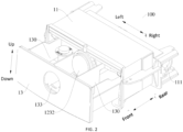
FIG. 2 is a schematic structural view of a dispensing device according to an embodiment of the present disclosure, in which a drawer is in an open state. -
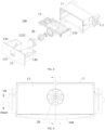
FIG. 3 is an exploded view of a structure of a dispensing device according to an embodiment of the present disclosure. -
FIG. 4 is a main view of a dispensing device according to an embodiment of the present disclosure. -
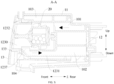
FIG. 5 is a cross-sectional view of a structure taken along line A-A inFIG. 4 . -
FIG. 6 is a cross-sectional view of a structure of a dispensing device except for a housing according to an embodiment of the present disclosure. -
FIG. 7 is a schematic structural view of a water passage component of a dispensing device in a viewing angle according to an embodiment of the present disclosure. -
FIG. 8 is a schematic structural view of a water passage component of a dispensing device in another viewing angle according to an embodiment of the present disclosure. -
FIG. 9 is a cross-sectional view of a structure of a water passage component of a dispensing device according to an embodiment of the present disclosure. -
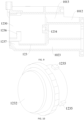
FIG. 10 is a schematic structural view of an end cover of a dispensing device in a viewing angle according to an embodiment of the present disclosure. -
FIG. 11 is a cross-sectional view of a structure of an end cover of a dispensing device according to an embodiment of the present disclosure. -
FIG. 12 is a schematic structural view of a sterilization assembly of a dispensing device according to an embodiment of the present disclosure. -
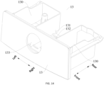
FIG. 13 is a schematic structural view of a drawer of a dispensing device in a viewing angle according to an embodiment of the present disclosure. -
FIG. 14 is a schematic structural view of a drawer of a dispensing device in another viewing angle according to an embodiment of the present disclosure. - Reference numerals:
- dispensing
device 100; - dispensing
case 10,water inflow channel 101, firstwater inflow channel 1011, secondwater inflow channel 1012, thirdwater inflow channel 1013,water outflow channel 102, firstwater outflow channel 1021, secondwater outflow channel 1022, thirdwater outflow channel 1023,distribution chamber 103, dispensingopening 104, -
outer shell 11,accommodation chamber 110,water inlet 111, -
water passage component 12, firstwater passage plate 121,side plate 1211,top plate 1212, secondwater passage plate 122,spray hole 1221,water inlet shell 123,water inlet chamber 1230, fixedshell 1231,end cover 1232,first shaft hole 1233,second shaft hole 1234,snap 1235,engagement groove 1236,first groove segment 12361,second groove segment 12362,communication opening 1237, -
drawer 13, dispensingchamber 130,avoidance recess 131,liquid leakage hole 132,avoidance hole 133, -
sterilization assembly 20,housing 21,water passing chamber 2101,water passing hole 2102,rotation shell 211, liftingrib 2111,blade 2112,rotation cover 212, firstrotary shaft 213, secondrotary shaft 214, andsterilization particle 22. - Embodiments of the present disclosure will be described in detail below with reference to examples thereof as illustrated in the accompanying drawings, throughout which same or similar elements, or elements having same or similar functions, are denoted by same or similar reference numerals. The embodiments described below with reference to the drawings are illustrative, and are only intended to explain, rather than limiting, the present disclosure.
- A dispensing
device 100 and a laundry treatment apparatus according to the embodiments of the present disclosure are described below with reference toFIG. 1 to FIG. 14 . - As shown in
FIG. 1 to FIG. 6 , thedispensing device 100 according to the embodiments of the present disclosure includes a dispensingcase 10 and asterilization assembly 20. The dispensingcase 10 defines awater inlet chamber 1230 and a dispensingchamber 130. Thewater inlet chamber 1230 and the dispensingchamber 130 are in communication with each other. The dispensingchamber 130 may be a dispensingchamber 130 configured to dispense a detergent, and thesterilization assembly 20 is disposed in thewater inlet chamber 1230. - During an operation, a water inlet valve is opened, and water flows into the
water inlet chamber 1230 of thedispensing device 100. The water flowing into thewater inlet chamber 1230 may impact thesterilization assembly 20, enabling the water to have a sterilization function. The water with the sterilization function flows out of thewater inlet chamber 1230 and then enters the dispensingchamber 130, and may be mixed with the detergent in the dispensingchamber 130, enabling the water to have sterilization, washing, and other functions for use in washing. - With the
dispensing device 100 according to the embodiments of the present disclosure, by providing thesterilization assembly 20 in thewater inlet chamber 1230, a sterilization water flow may be formed and is re-mixed with the detergent, i.e., release of sterilization substances and dilution and mixing of the detergent are realized successively through a one-way inflow of water with a simple structure and low cost. In this way, bacteria breeding can be effectively inhibited, stains can be removed, thereby ensuring cleanliness. Compared with the related art, a complicated structure of a water inlet pipeline can be avoided, and a space of the dispensing case can be effectively utilized. - As shown in
FIG. 5 andFIG. 6 , according to some embodiments of the present disclosure, thesterilization assembly 20 is rotatably disposed in thewater inlet chamber 1230, which allows the water to be in full contact with thesterilization assembly 20, greatly enhancing sterilization and bacteriostatic functions of the water. - The
sterilization assembly 20 is provided with a plurality ofblades 2112 on an outer peripheral wall of thesterilization assembly 20. The plurality ofblades 2112 is arranged at intervals in a circumferential direction of the outer peripheral wall of thesterilization assembly 20. During the operation, the water flowing into thewater inlet chamber 1230 impacts the plurality ofblades 2112, which drives thesterilization assembly 20 to rotate, bringing the water into full contact with thesterilization assembly 20. - As shown in
FIG. 6 , according to some embodiments of the present disclosure, thesterilization assembly 20 includes ahousing 21 andsterilization particles 22. Thehousing 21 has awater passing chamber 2101 and a plurality ofwater passing holes 2102. Thewater passing chamber 2101 and thewater inlet chamber 1230 may be in communication with each other via the plurality ofwater passing holes 2102. Thesterilization particles 22 are disposed in thewater passing chamber 2101. - In an exemplary embodiment of the present disclosure, the water flowing into the
water inlet chamber 1230 may flow into thewater passing chamber 2101 through the plurality ofwater passing holes 2102, and the water flowing into thewater passing chamber 2101 is in full contact with thesterilization particles 22, enabling the water to have the sterilization function. The sterilization water in thewater passing chamber 2101 may also flow to thewater inlet chamber 1230 through the plurality ofwater passing holes 2102, then flow into the dispensingchamber 130, and may be mixed with the detergent in the dispensingchamber 130 for use in washing. - As shown in
FIG. 6 , in some embodiments, thehousing 21 is provided with a plurality ofblades 2112 on an outer peripheral wall of thehousing 21. The plurality ofblades 2112 is arranged at intervals in a circumferential direction of the outer peripheral wall of thehousing 21. During the operation, the water flowing into thewater inlet chamber 1230 impacts theblades 2112 on thehousing 21, thereby driving thehousing 21 to rotate. When thehousing 21 rotates, thesterilization particles 22 in thewater passing chamber 2101 may be driven to move and rub against each other, which allowssolid sterilization particles 22 to be quickly released and to be fully mixed with the water, enabling the water to have the sterilization and bacteriostatic functions. - As shown in
FIG. 6 , in some embodiments, thewater passing chamber 2101 is provided with alifting rib 2111 on a wall surface of thewater passing chamber 2101. - In some specific embodiments, one
lifting rib 2111 may be provided, and thelifting rib 2111 extends in an axial direction of thehousing 21. When thehousing 21 rotates, thelifting rib 2111 may lift thesterilization particles 22 as moving upwards. As thehousing 21 continues to rotate, thesterilization particles 22 fall under an action of gravity, causing impact and friction with thehousing 21. In this way, thesolid sterilization particles 22 are quickly released and fully mixed with the water, enabling the water to have the sterilization and bacteriostatic functions. - In another specific embodiment, a plurality of lifting
ribs 2111 may be provided, and the plurality of liftingribs 2111 is arranged at intervals in the circumferential direction of the peripheral wall of thehousing 21. Each liftingrib 2111 extends in the axial direction of thehousing 21. By providing the plurality of liftingribs 2111, thesterilization particles 22 can be lifted by the plurality of liftingribs 2111 to further accelerate impact and friction frequency of thesterilization particles 22 with thehousing 21. - In some embodiments, the
housing 21 is a transparent member. By providing thehousing 21 as the transparent member, visibility of the sterilization function is improved. A user may not only observe rolling states of thesterilization particles 22 through thehousing 21 and add thesterilization particles 22 timely as needed, but may also form an intuitive feeling of the sterilization function, to improve user's trust and user experience. - In some specific embodiments, the
dispensing device 100 further includes a light-emitting member (not shown), which may irradiate an interior of thehousing 21, providing a more directly observable sterilization. - As shown in
FIG. 6 andFIG. 12 , in some embodiments, thehousing 21 includes arotation shell 211 and arotation cover 212. Therotation shell 211 has two ends, with one end having an opening. Therotation cover 211 is disposed at the opening of therotation shell 211 to close the opening of therotation shell 211. When therotation cover 212 is properly engaged with therotation shell 211, thewater passing chamber 2101 is defined by therotation cover 212 and therotation shell 211, and the plurality of thewater passing holes 2102 is formed at therotation shell 211 and/or therotation cover 212. - When the
sterilization assembly 20 is mounted in thewater inlet chamber 1230, another end of therotation shell 211 is rotatably engaged with a side wall of thewater inlet chamber 1230, and therotation cover 212 is rotatably engaged with another side wall of thewater inlet chamber 1230, i.e., both ends of thehousing 21 of thesterilization assembly 20 are rotatably engaged with the two opposite side walls of thewater inlet chamber 1230. In this way, it can be ensured that thehousing 21 can rotate within thewater inlet chamber 1230. - During the operation, the water flowing into the
water inlet chamber 1230 impacts the plurality ofblades 2112 on thehousing 21, driving thehousing 21 to rotate. When thehousing 21 rotates, thesterilization particles 22 may be driven to move and to impact and rub against thehousing 21. In this process, the water in thewater inlet chamber 1230 may enter thewater passing chamber 2101 through the plurality ofwater passing holes 2102, and is fully mixed with thesterilization particles 22, enabling the water to have the sterilization and bacteriostatic functions. Then, the water with the sterilization and bacteriostatic functions may flow into thewater inlet chamber 1230 through the plurality ofwater passing holes 2102, and finally flow into the dispensingchamber 130 to be mixed with detergent for use in washing. - As shown in
FIG. 5 to FIG. 9 , according to some embodiments of the present disclosure, the dispensingcase 10 defines awater inflow channel 101. Thewater inlet chamber 1230 and awater inlet 111 are in communication with each other via thewater inflow channel 101. The water may flow through thewater inflow channel 101 from thewater inlet 111, and then flow into thewater inlet chamber 1230 to be fully mixed with thesterilization assembly 20. Thewater inlet 111 may be directly connected to the water inlet valve, allowing the water to be introduced into thewater inlet chamber 1230. Thewater inlet 111 may also be connected to the water inlet valve through a pipeline. - Therefore, by forming the
water inflow channel 101 on the dispensingcase 10, thewater inlet chamber 1230 and thewater inlet 111 may be conveniently in communication with each other. Moreover, a shape and structure of thewater inflow channel 101 may be designed as needed, making it widely applicable. - Further, the dispensing
case 10 also defines awater outflow channel 102. Thewater inlet chamber 1230 and the dispensingchamber 130 are in communication with each other via thewater outflow channel 102. The water in thewater inlet chamber 1230 enters thewater passing chamber 2101 through the plurality ofwater passing holes 2102, and is fully mixed with thesterilization particles 22, enabling the water to have the sterilization and bacteriostatic functions. Then, the water with the sterilization and bacteriostatic functions may flow to thewater inlet chamber 1230 through the plurality ofwater passing holes 2102, and enter the dispensingchamber 130 through thewater outflow channel 102 to be mixed with the detergent for use in washing. - Therefore, by forming the
water outflow channel 102 on the dispensingcase 10, thewater inlet chamber 1230 and the dispensingchamber 130 may be conveniently in communication with each other. Moreover, a shape and structure of thewater outflow channel 102 may be designed as needed, making it widely applicable. - As shown in
FIG. 5 , in some embodiments, the dispensingcase 10 further defines adistribution chamber 103. Thewater outflow channel 102 and the dispensingchamber 130 are in communication with each other via thedistribution chamber 103. Thedistribution chamber 103 is located above the dispensingchamber 130. Thedistribution chamber 103 has a plurality ofspray holes 1221 formed on a bottom wall of thedistribution chamber 103. Thedistribution chamber 103 and the dispensingchamber 130 are in communication with each other via the plurality of spray holes 1221. - In an exemplary embodiment of the present disclosure, the water having the sterilization function in the
water inlet chamber 1230 may flow to thedistribution chamber 103 through thewater outflow channel 102. Since thedistribution chamber 103 is located above the dispensingchamber 130, the water in thedistribution chamber 103 may flow downwards to the dispensingchamber 130 through the spray holes 1221, to be mixed with the detergent in the dispensingchamber 130 for use in washing. - By providing the
distribution chamber 103 above the dispensingchamber 130, the water having the sterilization function may be directed to a designateddispensing chamber 130 to be mixed with the detergent in the designateddispensing chamber 130. Therefore, the structure is simple and cost is lowered. - In some specific embodiments, the
distribution chamber 103 and the dispensingchamber 130 are equal in quantity and located in a one-to-one correspondence. - For example, one
distribution chamber 103 and onedispensing chamber 130 may be provided respectively. Thedistribution chamber 103 is disposed directly above the dispensingchamber 130, and the water flowing into thedistribution chamber 103 may flow downwards through the plurality ofspray holes 1221 under the action of gravity, thereby flowing into the dispensingchamber 130. - For another example, two
distribution chambers 103 and two dispensingchambers 130 may be provided respectively. In an exemplary embodiment of the present disclosure, as shown, thedistribution chamber 103 includes afirst distribution chamber 103 at a left side and asecond distribution chamber 103 at a right side. Correspondingly, the dispensingchamber 130 includes afirst dispensing chamber 130 at a left side and asecond dispensing chamber 103 at a right side. Thefirst distribution chamber 103 is located directly above thefirst dispensing chamber 130, and thesecond distribution chamber 103 is located directly above thesecond dispensing chamber 130. The water in thewater inlet chamber 1230 may flow into thefirst distribution chamber 103 through thewater outflow channel 102, and then flow downwards to thefirst dispensing chamber 130 through a plurality ofspray holes 1221 on a bottom wall of thefirst distribution chamber 103; or the water in thewater inlet chamber 1230 may flow into thesecond distribution chamber 103 through thewater outflow channel 102, and then flow downwards to thesecond dispensing chamber 130 through a plurality ofspray holes 1221 on a bottom wall of thesecond distribution chamber 103. - In some other embodiments of the present disclosure, a plurality of (three or more)
distribution chambers 103 and a plurality of (three or more) dispensingchambers 130 may be provided respectively. The arrangements of the plurality ofdistribution chambers 103 and the plurality of dispensingchambers 130 may be designed as desired, and details thereof are omitted herein. - As shown in
FIG. 3 to FIG. 5 , in some specific embodiments, the dispensingcase 10 includes anouter shell 11 defining anaccommodation chamber 110 with an opening, and thewater inlet 111 is formed on theouter shell 11, i.e., theouter shell 11 may be used as an appearance and structure member of thedispensing device 100, the opening of theouter shell 11 may be disposed at a front part of theouter shell 11, and thewater inlet 111 may be disposed at a rear part of theouter shell 11. - As shown in
FIG. 5 to FIG. 9 , the dispensingcase 10 further includes awater passage component 12. Thewater passage component 12 is disposed in theouter shell 11 and defines thewater inlet chamber 1230. Thewater inflow channel 101, thewater outflow channel 102, and thedistribution chamber 103 may be defined by thewater passage component 12 itself or be defined between thewater passage component 12 and theouter shell 11. Alternatively, a part of each of thewater inflow channel 101, thewater outflow channel 102, and thedistribution chamber 103 are defined by thewater passage component 12 itself, and another part of each of thewater inflow channel 101, thewater outflow channel 102, and thedistribution chamber 103 are defined between thewater passage component 12 and theouter shell 11. This design is simple in structure and easy to be realized. - The
water passage component 12 and theouter shell 11 may be fixedly connected to each other by a fastener or may be connected to each other through a snap structure. - Further, as shown in
FIG. 3 ,FIG. 5 ,FIG. 13 , andFIG. 14 , the dispensingcase 10 further includes adrawer 13 adapted to be drawably disposed in theaccommodation chamber 110 through the opening. The dispensingchamber 130 is defined by thedrawer 13. By providing thedrawer 13, it is convenient for the user to dispense the detergent into the dispensingchamber 130, making the operation simple. - As shown in
FIG. 7 to FIG. 9 , in some examples, thewater passage component 12 includes a firstwater passage plate 121 and a secondwater passage plate 122. The firstwater passage plate 121 is disposed in theouter shell 11. A part of thewater outflow channel 102 and thewater inflow channel 101 are defined between the firstwater passage plate 121 and a side wall of theouter shell 11. The secondwater passage plate 122 is connected to an upper end of the firstwater passage plate 121. The secondwater passage plate 122 is disposed in theouter shell 11, and thedistribution chamber 103 is defined between the secondwater passage plate 122 and a top wall of theouter shell 11. This structure is simple and easy to be formed. - In some specific examples, the
water inflow channel 101 includes a firstwater inflow channel 1011, a secondwater inflow channel 1012, and a thirdwater inflow channel 1013. The firstwater inflow channel 1011 and the thirdwater inflow channel 1013 are in communication with each other via the secondwater inflow channel 1012. Thewater outflow channel 102 includes a firstwater outflow channel 1021, a secondwater outflow channel 1022, and a thirdwater outflow channel 1023. The firstwater outflow channel 1021 and the thirdwater outflow channel 1023 are in communication with each other via the secondwater outflow channel 1022. - The first
water inflow channel 1011 is defined between the firstwater passage plate 121 and an inner surface of the side wall of theouter shell 11. The secondwater inflow channel 1012 is defined between the firstwater passage plate 121 and an inner surface of the top wall of theouter shell 11. The thirdwater inflow channel 1012 is defined between the firstwater passage plate 121 and the secondwater passage plate 122. - The first
water outflow channel 1021 is defined between the firstwater passage plate 121 and the inner surface of the top wall of theouter shell 11, and the secondwater outflow channel 1022 is defined between the firstwater passage plate 121 and the inner surface of the side wall of theouter shell 11. - As shown in
FIG. 7 to FIG. 9 , further, thewater passage component 12 further includes awater inlet shell 123. Thewater inlet shell 123 is disposed below the secondwater passage plate 122, and is connected to the firstwater passage plate 121. Thewater inlet shell 123 defines thewater inlet chamber 1230. By providing thewater inlet shell 123, thewater inlet chamber 1230 for receiving thesterilization assembly 20 may be defined. In this way a space below the secondwater passage plate 122 can be effectively utilized, improving a space utilization rate. - In some examples, the
water inlet shell 123 further defines another part of thewater outflow channel 102, i.e., the thirdwater outflow channel 1023. The thirdwater outflow channel 1023 is located below thewater inlet chamber 1230. In an exemplary embodiment of the present disclosure, the thirdwater outflow channel 1023 extends in a length direction of the water inlet shell 123 (a front-rear direction as shown inFIG. 7 ), thewater inlet chamber 1230 has acommunication opening 1237 at a bottom wall of thewater inlet chamber 1230, and the thirdwater outflow channel 1023 is in communication with thecommunication opening 1237. In this way, the water in thewater inlet chamber 1230 can enter thewater outflow channel 102 through thecommunication opening 1237, and finally flow into the dispensingchamber 130 to be mixed with the detergent. - As shown in
FIG. 5 andFIG. 6 , in some examples, thewater inlet shell 123 includes a fixedshell 1231 and anend cover 1232. The fixedshell 1231 has an end connected to the firstwater passage plate 121 and another end with an opening. Theend cover 1232 is removably disposed at the opening of the fixedshell 1231. Thewater inlet chamber 1230 is defined between theend cover 1232 and the fixedshell 1231. By designing thewater inlet shell 123 of the above-described structure, it is convenient to remove thesterilization assembly 20. Moreover, thewater inlet shell 123 defines a position of thesterilization assembly 20, allowing thesterilization assembly 20 to effectively exert its sterilization function. - In some specific examples, the
end cover 1232 is rotationally snapped onto the fixedshell 1231. - In an exemplary embodiment of the present disclosure, a plurality of
snaps 1235 is provided at an outer peripheral wall of theend cover 1232. The plurality ofsnaps 1235 is arranged at intervals in a circumferential direction of the outer peripheral wall of theend cover 1232. Correspondingly, a plurality ofengagement grooves 1236 is provided at a position of an inner peripheral wall of the fixedshell 1231 adjacent to the opening. The plurality ofengagement grooves 1236 and the plurality ofsnaps 1235 are snapped and engaged with each other in a one-to-one correspondence to ensure connection reliability between the plurality ofengagement grooves 1236 and the plurality ofsnaps 1235, making assembly and disassembly more convenient. - The
engagement groove 1236 includes an opening. A dimension of the opening of the engagement groove 126 in a circumferential direction of the inner peripheral wall of the fixedshell 1231 is greater than or equal to a dimension of thesnap 1235 in the circumferential direction of the outer peripheral wall of theend cover 1232. Moreover, the opening of theengagement groove 1236 is formed into tapering opening. When theend cover 1232 is mounted on the fixedshell 1231, the plurality ofsnaps 1235 on theend cover 1232 is aligned with the openings of the plurality ofengagement grooves 1236 on the fixedshell 1231. Then, theend cover 1232 is pushed to slide inwards in an axial direction of the fixedshell 1231 and then is rotated, allowing thesnaps 1235 to slide into theengagement grooves 1236 deeply, ensuring a reliable connection between theend cover 1232 and the fixedshell 1231. - As shown in
FIG. 8 , in some specific examples, theengagement groove 1236 includes afirst groove segment 12361 and asecond groove segment 12362. Thefirst groove segment 12361 extends in the circumferential direction of the inner peripheral wall of the fixedshell 1231, and thesecond groove segment 12362 extends in an axial direction of the inner peripheral wall of the fixedshell 1231. An end of thesecond groove segment 12362 is formed as the opening of theengagement groove 1236, and another end of thesecond groove segment 12362 is in communication with an end of thefirst groove segment 12361. When theend cover 1232 and the fixedshell 1231 are assembled into place, thesnaps 1235 on theend cover 1232 are snapped and engaged with thefirst groove segment 12361. - In some specific examples, two ends of the
sterilization assembly 20 are rotatably engaged with theend cover 1232 and a bottom wall of the fixedshell 1231 respectively. As a result, it can be ensured that thesterilization assembly 20 can rotate in thewater inlet chamber 1230 under impact of the water flow. - For example, one of the
sterilization assembly 20 and theend cover 1232 has a rotary shaft, and the other one of thesterilization assembly 20 and theend cover 1232 has a shaft hole into which the rotary shaft is engaged. Similarly, one of thesterilization assembly 20 and the bottom wall of the fixedshell 1231 has a rotary shaft, and the other one of thesterilization assembly 20 and the bottom wall of the fixedshell 1231 has a shaft hole into which the rotary shaft is engaged. Therefore, it is simple in structure, convenient in assembly and disassembly, and easy to be implemented. - As shown in
FIG. 6 , in this embodiment, a firstrotary shaft 213 and a secondrotary shaft 214 are provided at two the ends of thesterilization assembly 20, respectively. Correspondingly, afirst shaft hole 1233 is formed at a part of theend cover 1232 facing towards thesterilization assembly 20, and asecond shaft hole 1234 is formed at a part of the bottom wall of the fixedshell 1231 facing towards thesterilization assembly 20. The firstrotary shaft 213 is engaged into thefirst shaft hole 1233, and the secondrotary shaft 214 is engaged into thesecond shaft hole 1234. In this way, it is ensured that thesterilization assembly 20 can rotate in thewater inlet chamber 1230. - In some specific examples, the first
water passage plate 121, the secondwater passage plate 122, and the fixedshell 1231 are integrally formed. By integrally forming the above structures, the number of components may be reduced, which omits structures such as a connection member, simplifying the structure. In addition, assembly steps may be reduced, which is beneficial to an improvement in production efficiency. - In some specific examples, the
drawer 13 has anavoidance hole 133. Theavoidance hole 133 is formed at a part of thedrawer 13 directly facing towards theend cover 1232 to expose theend cover 1232. - The
end cover 1232 has an annular stepped surface at the outer peripheral wall of theend cover 1232, and the annular stepped surface of theend cover 1232 is engaged into theavoidance hole 133. In this way, theend cover 1232 may be limited, to prevent theend cover 1232 from being separated from the fixedshell 1231, which further ensures mounting reliability and stability of thesterilization assembly 20. - In some specific examples, the
end cover 1232 is the transparent member. By providing theend cover 1232 as the transparent member, the visibility of the sterilization function is improved, and the user may observe a rotation state of thesterilization assembly 20 through theend cover 1232, to form the intuitive feeling of the sterilization function, improving the user's trust and user experience. - As shown in
FIG. 13 andFIG. 14 , in some embodiments, thedrawer 13 has an avoidance portion for avoiding thewater inlet shell 123, which ensures that thedrawer 13 can be mounted in place inside theouter shell 11, ensuring that thedispensing device 100 can be used normally. - In some specific embodiments, the dispensing
chamber 130 includes afirst dispensing chamber 130 and asecond dispensing chamber 130. Thefirst dispensing chamber 130 and thesecond dispensing chamber 130 are spaced apart from each other. The avoidance portion is formed as anavoidance recess 131 located between thefirst dispensing chamber 130 and thesecond dispensing chamber 130. Theavoidance recess 131 has aliquid leakage hole 132 formed on a bottom wall of theavoidance recess 131. By forming theliquid leakage hole 132 on theavoidance recess 131, it is ensured that water leaked from thewater inlet shell 123 can flow into theouter shell 11 and finally be dispensed into a designated component. Therefore, the water can be prevented from remaining in theavoidance recess 131. - In an exemplary embodiment of the present disclosure, the
drawer 13 includes a first dispensing box, a second dispensing box, and an outer shielding plate. The first dispensing box and the second dispensing box are spaced apart from each other at a side of the outer shielding plate. Thefirst dispensing chamber 130 is defined by the first dispensing box. Thesecond dispensing chamber 130 is defined by the second dispensing box. The first dispensing box and the second dispensing box are connected by a connection plate. In this way, structural compactness and a structural strength of thedrawer 13 are ensured, and deformation of thedrawer 13 is avoided. - Further, the connection plate has a
liquid leakage hole 132. Thus, it is ensured that the water leaked from thewater inlet shell 123 or water splashed onto the connection plate can flow into theouter shell 11 through theliquid leakage hole 132, and finally be dispensed into the designated component. Therefore, any liquid can be prevented from remaining on the connection plate. - A washing liquid or softening liquid may be placed in the
first dispensing chamber 130, and thefirst dispensing chamber 130 is internally provided with a siphonic structure, which can realize dispensing of the washing liquid or the softening liquid. Washing powder and the like may be placed in thesecond dispensing chamber 130, and a through opening is formed at a bottom wall and/or a side wall of thesecond dispensing chamber 130, which can realize dispensing of the washing powder. During the operation, the water in thewater inlet chamber 1230 may enter thefirst dispensing chamber 130 and thesecond dispensing chamber 130, respectively, to be mixed with the washing liquid or the softening liquid and the washing powder and finally used for washing. - In some embodiments, there is a gap between a bottom wall of the
drawer 13 and a bottom wall of theouter shell 11. When thedrawer 13 is in a closed state, a dispensingopening 103 is defined between an outer end of thedrawer 13 and an outer end of the bottom wall of theouter shell 11. In this way, the diluted detergent in the dispensingchamber 130 and the water with the sterilization function can be dispensed to a designated position. - A water passage structure of the
dispensing device 100 according to the embodiments of the present disclosure is described below with reference to the accompanying drawings. - According to some embodiments of the present disclosure, the
dispensing device 100 includes the dispensingcase 10 defining thewater inflow channel 101, thewater inlet chamber 1230, thewater outlet channel 102, and thedistribution chamber 103. An inlet of thewater inflow channel 101 is adapted to be in communication with thewater inlet 111, and an outlet of thewater inflow channel 101 is in communication with an inlet of thewater inlet chamber 1230. An outlet of thewater inlet chamber 1230 is in communication with an inlet of thewater outflow channel 102, and an outlet of thewater outflow channel 102 is in communication with thedistribution chamber 103. - In some embodiments, the
water inflow channel 101 includes the firstwater inflow channel 1011, the secondwater inflow channel 1012, and the thirdwater inflow channel 1013. The firstwater inflow channel 1011 has an end in communication with thewater inlet 111 and another end in communication with an end of the secondwater inflow channel 1012. The thirdwater inflow channel 1013 has an end in communication with the inlet of thewater inlet chamber 1230 and another end in communication with another end of the secondwater inflow channel 1012. - In some embodiments, the
water outflow channel 102 includes the firstwater outflow channel 1021, the secondwater outflow channel 1022, and the thirdwater outflow channel 1023. The firstwater outflow channel 1021 has an end in communication with thedistribution chamber 103 and another end in communication with an end of the secondwater outflow channel 1022. The thirdwater outflow channel 1023 has an end in communication with the outlet of thewater inlet chamber 1230 and another end in communication with another end of the secondwater outflow channel 1022. - The dispensing
case 10 has a horizontal direction, a longitudinal direction, and a vertical direction. The horizontal direction may be a left-right direction shown inFIG. 7 , the longitudinal direction may be a front-rear direction shown inFIG. 7 , and the vertical direction may be an up-down direction shown inFIG. 7 . - The first
water inflow channel 1011 extends in the vertical direction. The secondwater inflow channel 1012 extends in the horizontal direction. The thirdwater inflow channel 1013 extends in the longitudinal direction. Moreover, the firstwater inflow channel 1011 is located below the thirdwater inflow channel 1013. Further, the firstwater outflow channel 1021 extends in the longitudinal direction, the secondwater outflow channel 1022 extends in the vertical direction, the thirdwater outflow channel 1023 extends in the longitudinal direction, and the firstwater outflow channel 1021 is located above the thirdwater outflow channel 1023. - The first
water inflow channel 1011 and the secondwater outflow channel 1022 are in one vertical plane. The secondwater inflow channel 1012 and the firstwater outflow channel 1021 are in one horizontal plane. The thirdwater inflow channel 1013 is located directly above the thirdwater outflow channel 1023. - It should be noted that the number of first
water outflow channels 1021 may be equal to the number ofdistribution chambers 103. For example, a plurality of firstwater outflow channels 1021 and a plurality ofdistribution chambers 103 may be provided, respectively. Ends of the plurality of firstwater outflow channels 1021 are in communication with the plurality ofdistribution chambers 103 in a one-to-one correspondence, and the other end of the plurality of firstwater outflow channels 1021 are in communication with one secondwater outflow channel 1022. - In some examples, the third
water inflow channel 1013 is located directly above the thirdwater outflow channel 1023, and the inlet of thewater inlet chamber 1230 is located above the outlet of thewater inlet chamber 1230. - Further, the
distribution chamber 103 is located above thewater inlet chamber 1230. In some specific examples, two ormore distribution chambers 103 may be provided, and thewater inlet chamber 1230 is disposed between twoadjacent distribution chambers 103 to ensure that water in thedistribution chambers 103 may be dispensed to a corresponding position. - According to some embodiments of the present disclosure, the dispensing
case 10 includes theouter shell 11 and thewater passage component 12. Thewater passage component 12 is disposed in theouter shell 11. Thewater passage component 12 includes the firstwater passage plate 121, the secondwater passage plate 122, and thewater inlet shell 123. - The first
water passage plate 121 includes aside plate 1211 and atop plate 1212. An upper end of theside plate 1211 is connected to thetop plate 1212. The firstwater outflow channel 1021 and the secondwater inflow channel 1012 are defined between thetop plate 1212 of the firstwater passage plate 121 and the top wall of theouter shell 11. The firstwater inflow channel 1011 and the secondwater outflow channel 1022 are defined between theside plate 1211 of the firstwater passage plate 121 and the side wall of theouter shell 11. - The second
water passage plate 122 is disposed above thetop plate 1212 of the firstwater passage plate 121, and the thirdwater inflow channel 1013 is defined between the secondwater passage plate 122 and the top plate. Thedistribution chamber 103 is defined between the secondwater passage plate 122 and the top wall of theouter shell 11. - The
water inlet shell 123 is disposed below the secondwater passage plate 122 and connected to theside plate 1211 of the firstwater passage plate 121. Thewater inlet shell 123 defines thewater inlet chamber 1230 and the thirdwater outflow channel 1023 located below thewater inlet chamber 1230. - Therefore, the first
water passage plate 121, the secondwater passage plate 122, and thewater inlet shell 123 cooperate with theouter shell 11 to define the water inflow channel and the water outflow channel. - The first
water passage plate 121 is provided with a first water-separating rib, which can separate thewater inflow channel 101 from thewater outflow channel 102. The secondwater passage plate 122 is provided with a second water-separating rib, which can separate the plurality ofdistribution chambers 103 from each other. - The
drawer 13 of thedispensing device 100 according to the embodiments of the present disclosure is described below with reference to the accompanying drawings, - As shown in
FIG. 13 andFIG. 14 , according to some embodiments of the present disclosure, thedrawer 13 includes the outer shieling plate and the dispensing box. A side surface of the outer shielding plate is formed as an appearance surface of thedispensing device 100. The dispensing box is connected to another side surface of the outer shielding plate and defines a dispensingchamber 130 with a top opening. Further, the avoidance portion is further provided at a side of the outer shielding plate facing away from the appearance surface and configured to avoid the sterilization assembly. - In some embodiments, the avoidance portion is formed as the connection plate, and the connection plate is connected to the dispensing box and the outer shielding plate, respectively. The connection plate is located below the sterilization assembly when the
drawer 13 is in the closed state. In some specific embodiments, the sterilization assembly is disposed in thewater inlet shell 123 of the dispensingcase 10 of thedispensing device 100, and the connection plate is located below thewater inlet shell 123 when thedrawer 13 is in the closed state. - In some specific embodiments, the connection plate has the plurality of
liquid leakage holes 132 to ensure that the water splashed onto the connection plate can flow out from the liquid leakage holes 132. Therefore, any liquid can be prevented from remaining on the connection plate. - In an exemplary embodiment of the present disclosure, as shown in
FIG. 13 , the plurality ofliquid leakage holes 132 may be arranged at intervals in a length direction and/or a width direction of the connection plate. For example, the plurality ofliquid leakage holes 132 are arranged on the connection plate in groups. The groups of the plurality ofliquid leakage holes 132 are arranged at intervals in the length direction of the connection plate. A plurality ofliquid leakage holes 132 in each group ofliquid leakage holes 132 are arranged at intervals in the width direction of the connection plate. A plurality ofliquid leakage holes 132 of two adjacent groups ofliquid leakage holes 132 are alternatively arranged in the width direction of the connection plate. - The
liquid leakage hole 132 may be formed into an elongated hole, a circular hole, or the like. - In some embodiments, two dispensing boxes are provided and include the first dispensing box and the second dispensing box, respectively. The first dispensing box and the second dispensing box are spaced apart from each other in a length direction of the outer shielding plate. The connection plate is connected between the first dispensing box and the second dispensing box. The avoidance portion is defined by the first dispensing box, the second dispensing box, and the connection plate, and the connection plate is formed as a bottom wall of the avoidance portion. When the
drawer 13 is in the closed state, the connection plate is located below thewater inlet shell 123 and between the first dispensing box and the second dispensing box. - In some embodiments, the
avoidance hole 133 is formed at a part of the outer shielding plate corresponding to the avoidance portion. Theavoidance hole 133 corresponds to a position of the end cover of thewater inlet shell 123. When thedrawer 13 is in the closed state, the end cover of thewater inlet shell 123 is exposed. The end cover of thewater inlet shell 123 may be a transparent member. In this way, when thedrawer 13 is closed, the user may observe the sterilization assembly through theavoidance hole 133 outside thedispensing device 100. - The
avoidance hole 133 may be a circular hole or a square hole. A shape of theavoidance hole 133 may be the same as or different from a shape of the end cover of thewater inlet shell 123. In order to ensure appearance aesthetic of thedispensing device 100, a size of theavoidance hole 133 may be smaller than or equal to a size of a side of the end cover facing towards the outer shielding plate, to prevent needless structures from being exposed from theavoidance hole 133 and affecting the appearance of thedispensing device 100. - A laundry treatment apparatus according to the embodiments of the present disclosure is described below with reference to the accompanying drawings.
- The laundry treatment apparatus according to the embodiments of the present disclosure includes the
dispensing device 100 according to the above-described embodiments. The laundry treatment apparatus may be a washing machine (for example, a front-loaded washing machine or a top-loaded washing machine) or a combined washing and drying machine. - Since the
dispensing device 100 according to the embodiments of the present disclosure has the above-described technical effects, the laundry treatment apparatus according to the embodiments of the present disclosure also has the above-described technical effects. That is, by employing thedispensing device 100, the bacteria breeding can be effectively inhibited, and the stains can be removed, ensuring the cleanliness. Compared with the related art, the space is also saved, and the space of the dispensingcase 10 is effectively utilized. - In some embodiments, the laundry treatment apparatus includes a washing tub, and the dispensing opening 103 of the
dispensing device 100 is in communication with the washing tub. In this way, the diluted detergent and the water having the sterilization function can be dispensed into the washing tub. - With the laundry treatment apparatus according to the embodiments of the present disclosure, by disposing the
sterilization assembly 20 in thewater inlet chamber 1230 of the dispensingcase 10, a workbench space of the laundry treatment apparatus is saved. Moreover, the release of thesterilization particles 22 and the dilution and mixing of the detergent are successively realized through a one-way inflow of water with a simple structure and low cost. - Furthermore, since the
drawer 13 is closed for a long time, an internal environment of thedrawer 13 is relatively closed and humid. When thedrawer 13 is not frequently pulled out for cleaning and ventilation, bacteria are easily bred in thedrawer 13. When thedispensing device 100 in the present disclosure is in use, thedrawer 13 is flushed with the water having the sterilization function, which can effectively inhibit the bacteria breeding and keep thedrawer 13 clean. - In the description of the present disclosure, it should be understood that, orientation or position relationship indicated by terms such as "center", "longitudinal", "lateral", "length", "width", "thickness", "over", "below", "front", "back", "left", "right", "vertical", "horizontal", "top", "bottom", "in", "out", "axial", "radial", and "circumferential" is based on the orientation or position relationship shown in the accompanying drawings, and is merely for the convenience of describing the present disclosure and simplifying the description, rather than indicating or implying that the associated device or element must have a specific orientation, or be constructed and operated in a specific orientation, and therefore cannot be understood as a limitation on the present disclosure.
- Other configurations and operations of the laundry treatment apparatus according to embodiments of the present disclosure are known to those of ordinary skill in the art, and detailed description thereof will be omitted herein.
- In the description of this specification, descriptions with reference to the terms "an embodiment", "some embodiments", "schematic embodiments", "examples", "specific examples", or "some examples", etc. mean that specific features, structure, materials, or characteristics described in conjunction with the embodiment or example are included in at least one embodiment or example of the present disclosure. In this specification, the schematic representations of the above terms do not necessarily refer to the same implementation or example. Moreover, the described specific features, structures, materials or characteristics may be combined in any one or more embodiments or examples in a suitable manner.
- Although the embodiments of the present disclosure have been shown and described above, it should be understood by those of ordinary skilled in the art that various changes, modifications, replacements, and variations can be made to these embodiments without departing from the principles and ideas of the present disclosure. The scope of the present disclosure is defined by the claims as appended and their equivalents.
Claims (20)
- A dispensing device, comprising:a dispensing case defining a water inlet chamber and a dispensing chamber dispensing a detergent, the water inlet chamber and the dispensing chamber being in communication with each other; anda sterilization assembly disposed in the water inlet chamber.
- The dispensing device according to claim 1, wherein the sterilization assembly is rotatably disposed in the water inlet chamber.
- The dispensing device according to claim 2, wherein the sterilization assembly is provided with a plurality of blades on an outer peripheral wall of the sterilization assembly, the plurality of blades being arranged at intervals in a circumferential direction of the outer peripheral wall of the sterilization assembly.
- The dispensing device according to any one of claims 1 to 3, wherein the sterilization assembly comprises:a housing having a water passing chamber and a plurality of water passing holes, the water passing chamber and the water inlet chamber being in communication with each other via the plurality of water passing holes; andsterilization particles disposed in the water passing chamber.
- The dispensing device according to claim 4, wherein the water passing chamber is provided with a lifting rib on a wall surface of the water passing chamber.
- The dispensing device according to claim 4 or 5, wherein the housing is a transparent member.
- The dispensing device according to any one of claims 4 to 6, wherein the housing comprises:a rotation shell having an end with an opening; anda rotation cover disposed at the opening of the rotation shell, the water passing chamber being defined by the rotation cover and the rotation shell, wherein:another end of the rotation shell and the rotation cover are respectively rotatably engaged with two opposite side walls of the water inlet chamber; andthe plurality of the water passing holes is formed at the rotation shell and/or the rotation cover.
- The dispensing device according to any one of claims 1 to 7, wherein the dispensing case defines a water inflow channel and a water outflow channel, the water inlet chamber and a water inlet being in communication with each other via the water inflow channel, and the water inlet chamber and the dispensing chamber being in communication with each other via the water outflow channel.
- The dispensing device according to claim 8, wherein the dispensing case further defines a distribution chamber, the water outflow channel and the dispensing chamber being in communication with each other via the distribution chamber, wherein:the distribution chamber is located above the dispensing chamber; andthe distribution chamber has a plurality of spray holes formed on a bottom wall of the distribution chamber, the distribution chamber and the dispensing chamber being in communication with each other via the plurality of spray holes.
- The dispensing device according to claim 9, wherein the distribution chamber and the dispensing chamber are equal in quantity and located in a one-to-one correspondence.
- The dispensing device according to claim 9 or 10, wherein the dispensing case comprises:an outer shell defining an accommodation chamber, the accommodation chamber having an opening formed on a side of the accommodation chamber, and the water inlet being formed on the outer shell;a water passage component disposed in the outer shell and defining the water inlet chamber, the water inflow channel, the water outflow channel, and the distribution chamber being defined by the water passage component itself and/or being defined between the water passage component and the outer shell; anda drawer adapted to be drawably disposed in the accommodation chamber through the opening, the dispensing chamber being defined by the drawer.
- The dispensing device according to claim 11, wherein the water passage component comprises:a first water passage plate disposed in the outer shell, the water inflow channel and a part of the water outflow channel being defined between the first water passage plate and a side wall of the outer shell;a second water passage plate connected to an upper end of the first water passage plate, the second water passage plate being disposed in the outer shell, and the distribution chamber being defined between the second water passage plate and a top wall of the outer shell; anda water inlet shell disposed below the second water passage plate and connected to the first water passage plate, the water inlet shell defining the water inlet chamber.
- The dispensing device according to claim 12, wherein the water inlet shell further defines another part of the water outflow channel, the other part of the water outlet flow channel being located below the water inlet chamber.
- The dispensing device according to claim 12, wherein the water inlet shell comprises:a fixed shell having an end connected to the first water passage plate and another end with an opening; andan end cover detachably disposed at the opening of the fixed shell, the water inlet chamber being defined between the end cover and the fixed shell.
- The dispensing device according to claim 14, wherein two ends of the sterilization assembly are respectively rotatably engaged with the end cover and a bottom wall of the fixed shell.
- The dispensing device according to claim 14 or 15, wherein the drawer has an avoidance hole positioned directly facing the end cover to expose the end cover.
- The dispensing device according to claim 16, wherein the end cover is a transparent member.
- The dispensing device according to any one of claims 12 to 17, wherein the drawer has an avoidance portion for avoiding the water inlet shell.
- The dispensing device according to claim 18, wherein the dispensing chamber comprises a first dispensing chamber and a second dispensing chamber (130), wherein the second dispensing chamber (130) is spaced apart from the first dispensing chamber, the avoidance portion being formed as an avoidance recess located between the first dispensing chamber and the second dispensing chamber, and the avoidance recess having a liquid leakage hole formed on a bottom wall of the avoidance recess.
- A laundry treatment apparatus, comprising a dispensing device according to any one of claims 1 to 19.
Applications Claiming Priority (2)
| Application Number | Priority Date | Filing Date | Title |
|---|---|---|---|
| CN202210304990.2A CN116837604B (en) | 2022-03-25 | 2022-03-25 | Dispensing device and clothing processing equipment |
| PCT/CN2023/081555 WO2023179417A1 (en) | 2022-03-25 | 2023-03-15 | Dispensing device and laundry treatment apparatus |
Publications (2)
| Publication Number | Publication Date |
|---|---|
| EP4495315A1 true EP4495315A1 (en) | 2025-01-22 |
| EP4495315A4 EP4495315A4 (en) | 2025-07-09 |
Family
ID=88099846
Family Applications (1)
| Application Number | Title | Priority Date | Filing Date |
|---|---|---|---|
| EP23773665.7A Pending EP4495315A4 (en) | 2022-03-25 | 2023-03-15 | DISPENSING DEVICE AND LAUNDRY TREATMENT DEVICE |
Country Status (4)
| Country | Link |
|---|---|
| EP (1) | EP4495315A4 (en) |
| JP (1) | JP7838109B2 (en) |
| CN (1) | CN116837604B (en) |
| WO (1) | WO2023179417A1 (en) |
Families Citing this family (2)
| Publication number | Priority date | Publication date | Assignee | Title |
|---|---|---|---|---|
| CN116837603B (en) * | 2022-03-25 | 2026-03-20 | 无锡小天鹅电器有限公司 | Dispensing device and clothing processing equipment |
| CN116837600B (en) * | 2022-03-25 | 2026-03-20 | 无锡小天鹅电器有限公司 | Dispensing device and clothing processing equipment |
Family Cites Families (17)
| Publication number | Priority date | Publication date | Assignee | Title |
|---|---|---|---|---|
| KR20010010112A (en) * | 1999-07-16 | 2001-02-05 | 윤종용 | Detergent feed device and control method of washing machine |
| JP2002331196A (en) * | 2001-05-09 | 2002-11-19 | Toshiba Corp | Washing machine |
| JP4017504B2 (en) | 2002-11-19 | 2007-12-05 | シャープ株式会社 | Washing machine |
| JP4476274B2 (en) * | 2006-02-14 | 2010-06-09 | シャープ株式会社 | Washing machine |
| CN201620282U (en) * | 2010-01-05 | 2010-11-03 | 胡积献 | Sterilizing device for washing machine |
| DE102012210051A1 (en) * | 2012-06-14 | 2013-12-19 | Christian Lauke | Microbicidal storage |
| CN206279361U (en) * | 2016-11-10 | 2017-06-27 | 松下家电研究开发(杭州)有限公司 | A kind of detergent box and washing machine |
| CN207003060U (en) * | 2017-05-23 | 2018-02-13 | 翁霖 | A kind of disinfecting washing machine |
| CN206887517U (en) * | 2017-05-23 | 2018-01-16 | 无锡小天鹅股份有限公司 | The delivery device and washing machine of washing machine |
| CN109112787A (en) * | 2017-06-23 | 2019-01-01 | 无锡小天鹅股份有限公司 | Washing machine |
| CN210314929U (en) * | 2019-06-20 | 2020-04-14 | 南京创维家用电器有限公司 | Detachable silver ion container structure |
| WO2021085162A1 (en) * | 2019-10-31 | 2021-05-06 | パナソニックIpマネジメント株式会社 | Washing machine |
| CN112430980A (en) * | 2020-12-05 | 2021-03-02 | 安徽信息工程学院 | Automatic sterilization shared washing machine |
| CN215104062U (en) * | 2021-03-29 | 2021-12-10 | 海信(山东)冰箱有限公司 | Washing machine |
| WO2022262522A1 (en) * | 2021-06-18 | 2022-12-22 | 青岛海尔洗衣机有限公司 | Washing machine |
| CN217052748U (en) * | 2022-03-25 | 2022-07-26 | 无锡小天鹅电器有限公司 | Drawer of feeding device, feeding device and clothes treatment equipment |
| CN217459963U (en) * | 2022-05-31 | 2022-09-20 | 无锡小天鹅电器有限公司 | Put in device and clothes treatment equipment that has it |
-
2022
- 2022-03-25 CN CN202210304990.2A patent/CN116837604B/en active Active
-
2023
- 2023-03-15 EP EP23773665.7A patent/EP4495315A4/en active Pending
- 2023-03-15 JP JP2024556770A patent/JP7838109B2/en active Active
- 2023-03-15 WO PCT/CN2023/081555 patent/WO2023179417A1/en not_active Ceased
Also Published As
| Publication number | Publication date |
|---|---|
| CN116837604A (en) | 2023-10-03 |
| JP7838109B2 (en) | 2026-03-31 |
| WO2023179417A1 (en) | 2023-09-28 |
| EP4495315A4 (en) | 2025-07-09 |
| CN116837604B (en) | 2025-01-24 |
| JP2025510262A (en) | 2025-04-14 |
Similar Documents
| Publication | Publication Date | Title |
|---|---|---|
| US10508380B2 (en) | Washing machine | |
| CA2949780C (en) | Washing machine | |
| US20160326684A1 (en) | Washing machine control panel base with function of automatically adding detergent | |
| CN108866957B (en) | Washing machine and detergent device thereof | |
| CN217052748U (en) | Drawer of feeding device, feeding device and clothes treatment equipment | |
| CN108866956B (en) | Washing machine and its detergent device | |
| CN217459963U (en) | Put in device and clothes treatment equipment that has it | |
| JP7838109B2 (en) | Input device and garment processing device | |
| WO2023179686A1 (en) | Dispensing device and laundry treatment apparatus | |
| WO2023179688A1 (en) | Dispenser device and clothes treatment apparatus | |
| CN116837600B (en) | Dispensing device and clothing processing equipment | |
| CN215758108U (en) | Detergent Box and Washing Machine | |
| JP7519468B2 (en) | Detergent dissolving device and washing machine | |
| CN116837602B (en) | Dispensing device and clothing processing equipment | |
| CN114438738B (en) | Outer drum cover and washing machine | |
| CN216585732U (en) | Washing machine and control panel seat and water inlet box assembly thereof | |
| CN112760939B (en) | Detergent feeding device and washing machine | |
| JP7490083B2 (en) | washing machine | |
| CN207904579U (en) | Detergent box and roller washing machine | |
| US20260049432A1 (en) | Laundry machine | |
| CN221566580U (en) | Drum washing machine | |
| CN221566581U (en) | Drum washing machine | |
| CN120174599A (en) | Drum washing machine | |
| CN217017782U (en) | Cleaning mechanism and paint mixing equipment for pulp nozzle | |
| US20260049431A1 (en) | Laundry machine |
Legal Events
| Date | Code | Title | Description |
|---|---|---|---|
| STAA | Information on the status of an ep patent application or granted ep patent |
Free format text: STATUS: THE INTERNATIONAL PUBLICATION HAS BEEN MADE |
|
| PUAI | Public reference made under article 153(3) epc to a published international application that has entered the european phase |
Free format text: ORIGINAL CODE: 0009012 |
|
| STAA | Information on the status of an ep patent application or granted ep patent |
Free format text: STATUS: REQUEST FOR EXAMINATION WAS MADE |
|
| 17P | Request for examination filed |
Effective date: 20241018 |
|
| AK | Designated contracting states |
Kind code of ref document: A1 Designated state(s): AL AT BE BG CH CY CZ DE DK EE ES FI FR GB GR HR HU IE IS IT LI LT LU LV MC ME MK MT NL NO PL PT RO RS SE SI SK SM TR |
|
| DAV | Request for validation of the european patent (deleted) | ||
| DAX | Request for extension of the european patent (deleted) | ||
| A4 | Supplementary search report drawn up and despatched |
Effective date: 20250605 |
|
| RIC1 | Information provided on ipc code assigned before grant |
Ipc: D06F 35/00 20060101ALN20250530BHEP Ipc: D06F 39/02 20060101AFI20250530BHEP |