EP4495313A1 - Lift device for front loading washing machine and front loading washing machine - Google Patents
Lift device for front loading washing machine and front loading washing machine Download PDFInfo
- Publication number
- EP4495313A1 EP4495313A1 EP23769560.6A EP23769560A EP4495313A1 EP 4495313 A1 EP4495313 A1 EP 4495313A1 EP 23769560 A EP23769560 A EP 23769560A EP 4495313 A1 EP4495313 A1 EP 4495313A1
- Authority
- EP
- European Patent Office
- Prior art keywords
- guide column
- washing machine
- counterweight
- lifting device
- drum washing
- Prior art date
- Legal status (The legal status is an assumption and is not a legal conclusion. Google has not performed a legal analysis and makes no representation as to the accuracy of the status listed.)
- Granted
Links
Images


Classifications
-
- D—TEXTILES; PAPER
- D06—TREATMENT OF TEXTILES OR THE LIKE; LAUNDERING; FLEXIBLE MATERIALS NOT OTHERWISE PROVIDED FOR
- D06F—LAUNDERING, DRYING, IRONING, PRESSING OR FOLDING TEXTILE ARTICLES
- D06F37/00—Details specific to washing machines covered by groups D06F21/00 - D06F25/00
- D06F37/02—Rotary receptacles, e.g. drums
- D06F37/04—Rotary receptacles, e.g. drums adapted for rotation or oscillation about a horizontal or inclined axis
- D06F37/06—Ribs, lifters, or rubbing means forming part of the receptacle
- D06F37/065—Ribs, lifters, or rubbing means forming part of the receptacle ribs or lifters having means for circulating the washing liquid
-
- D—TEXTILES; PAPER
- D06—TREATMENT OF TEXTILES OR THE LIKE; LAUNDERING; FLEXIBLE MATERIALS NOT OTHERWISE PROVIDED FOR
- D06F—LAUNDERING, DRYING, IRONING, PRESSING OR FOLDING TEXTILE ARTICLES
- D06F39/00—Details of washing machines not specific to a single type of machines covered by groups D06F9/00 - D06F27/00
- D06F39/08—Liquid supply or discharge arrangements
- D06F39/083—Liquid discharge or recirculation arrangements
-
- D—TEXTILES; PAPER
- D06—TREATMENT OF TEXTILES OR THE LIKE; LAUNDERING; FLEXIBLE MATERIALS NOT OTHERWISE PROVIDED FOR
- D06F—LAUNDERING, DRYING, IRONING, PRESSING OR FOLDING TEXTILE ARTICLES
- D06F23/00—Washing machines with receptacles, e.g. perforated, having a rotary movement, e.g. oscillatory movement, the receptacle serving both for washing and for centrifugally separating water from the laundry
- D06F23/02—Washing machines with receptacles, e.g. perforated, having a rotary movement, e.g. oscillatory movement, the receptacle serving both for washing and for centrifugally separating water from the laundry and rotating or oscillating about a horizontal axis
- D06F23/025—Washing machines with receptacles, e.g. perforated, having a rotary movement, e.g. oscillatory movement, the receptacle serving both for washing and for centrifugally separating water from the laundry and rotating or oscillating about a horizontal axis with a rotatable imperforate tub
Definitions
- the present disclosure relates to the technical field of washing machines, and specifically provides a lifting device for a drum washing machine, and a drum washing machine.
- the centrifugal drainage assembly includes a centrifugal member that generates centrifugal motion under the action of centrifugal force, and the centrifugal member includes a connecting part and a counterweight member; one end of the connecting part is connected to the counterweight member, and the other end of the connecting part is rotatably connected to a sealing plunger; a middle portion of the connecting part is rotatably installed on a plunger seat, forming a lever structure".
- This patent proposes a solution of using the centrifugal assembly to achieve centrifugal drainage, so as to solve the drainage problem of the hole-free drum washing machine.
- the inventor found that with increasing use of the washing machine, due to the unreasonable arrangement of the counterweight member, the increasing times of swinging thereof will cause the wear of rotating shaft, which further causes problems of noise production and structural instability, ultimately leading to untight blocking of drainage outlet and inability to adjust the centrifugal assembly, and eventually resulting in the replacement of the centrifugal assembly.
- the solution of the prior application still has the problem of insufficient service life.
- the inventor continues to propose a new structure for improvement to make the drum washing machine less prone to noise production and have a longer service life.
- the present disclosure aims to solve the above technical problem, that is, to solve the problem of reduced service life caused by unreasonable arrangement of the centrifugal assembly in the lifting device of existing drum washing machines.
- the present disclosure provides a lifting device for a drum washing machine, which includes a housing with a cavity structure; a centrifugal assembly is arranged inside the cavity structure, and the centrifugal assembly includes a valve body guide column, a valve core, a counterweight guide column, a counterweight member, a balancing rod, and an elastic member; a middle part of the balancing rod is pivotally connected inside the housing; a first end of the balancing rod is hinged to a first end of the counterweight guide column, a second end of the counterweight guide column is connected to the counterweight member after passing through a first through hole on the housing, and the counterweight guide column is slidably arranged in the first through hole; the elastic member is arranged between the counterweight guide column and the housing, and is used to reset the position of the counterweight member; a second end of the balancing rod is hinged to a first end of the valve body guide column, a second end of the valve body guide column is connected to the valve core after passing
- the housing includes a cover shaped lifting rib shell and a bracket arranged at an opening of the lifting rib shell, and the first through hole and the second through hole are arranged on the bracket.
- the counterweight guide column includes a first connecting lug and a first sliding rod arranged on the first connecting lug; the first end of the balancing rod is hinged to the first connecting lug, and a boss is arranged between the first connecting lug and the first sliding rod; the elastic member is a spring, which is sleeved on the first sliding rod; one end of the spring is abuts against the boss, and the other end of the spring abuts against an inner surface of the bracket.
- the first sliding rod is threaded with the counterweight member, and the counterweight member abuts against an outer surface of the bracket.
- a size of the counterweight member is larger than a size of the first through hole, and/or a size of the valve core is larger than a size of the second through hole.
- the valve body guide column includes a second connecting lug and a second sliding rod arranged on the second connecting lug; the second end of the balancing rod is hinged to the second connecting lug, the valve core is detachably connected to the second sliding rod, and a sealing member is also arranged at the top of the valve core.
- annular sealing rib is also arranged at the bottom of the sealing member.
- a support seat is arranged on the bracket, and a middle part of the balancing rod is pivotally connected to the support seat; and/or water passing holes are arranged on the lifting rib shell.
- the counterweight member and the counterweight guide column are separately arranged or integrally formed; and/or the valve body guide column and the valve core are separately arranged or integrally formed.
- the present disclosure also provides a drum washing machine, which includes an outer cylinder, and an inner cylinder that is rotatably arranged inside the outer cylinder; the inner cylinder is provided with a clothing inlet that cooperates with a door of the washing machine, a water inlet connected to a water inflow pipe, and a water outlet; the lifting device for a drum washing machine according to any one of claims 1-9 is provided on the water outlet, and the valve core of the lifting device is arranged at the water outlet, so that when the door is closed, the water inlet is closed and the valve core blocks the water outlet, the inner cylinder is a closed chamber, and when the door is closed, the water inlet is closed and the valve core disengages from the water outlet, the inner cylinder can drain water normally.
- the lifting device for a drum washing machine includes a housing with a cavity structure; a centrifugal assembly is arranged inside the cavity structure, and the centrifugal assembly includes a valve body guide column, a valve core, a counterweight guide column, a counterweight member, a balancing rod, and an elastic member; a middle part of the balancing rod is pivotally connected inside the housing; a first end of the balancing rod is hinged to a first end of the counterweight guide column, a second end of the counterweight guide column is connected to the counterweight member after passing through a first through hole on the housing, and the counterweight guide column is slidably arranged in the first through hole; the elastic member is arranged between the counterweight guide column and the housing, and is used to reset the position of the counterweight member; a second end of the balancing rod is hinged to a first end of the valve body guide column, a second end of the valve body guide column is
- the centrifugal assembly is provided inside the lifting device in the present disclosure, and the middle rotating shaft at the middle part of the balancing rod is used as a fixed shaft, so that the counterweight guide column and the valve body guide column hinged at both ends of the balancing rod respectively can perform a lever motion.
- the counterweight member is arranged at the second end of the counterweight guide column, so that the valve body guide column can drive the valve core to disengage from the water outlet.
- a spring is provided on an inner surface of the housing at the top of the counterweight member, and the spring can provide a pre-pressure for the valve core.
- the counterweight member Under the action of the spring which simultaneously exerts a certain pressure to the housing and the first end of the balancing rod, the counterweight member abuts against an outer surface of the housing under the action of the force of the spring, and the other end of the spring transfers the force received by the first end of the balancing rod to the second end of the balancing rod, and then to the second end of the valve body guide column, ultimately tightly sealing the valve core at the water outlet by the valve body guide column.
- the inner cylinder rotates at a high speed.
- valve body guide column moves in a direction toward an axial center the inner cylinder until the valve core disengages from the water outlet to achieve drainage of the washing machine.
- connection may be a fixed connection, or a detachable connection, or an integral connection; it may be a mechanical connection, or an electrical connection; it may be a direct connection, or an indirect connection implemented through an intermediate medium, or internal communication between two elements.
- connection may be a fixed connection, or a detachable connection, or an integral connection; it may be a mechanical connection, or an electrical connection; it may be a direct connection, or an indirect connection implemented through an intermediate medium, or internal communication between two elements.
- the lifting device 1 for a drum washing machine 3 of the present disclosure includes a housing with a cavity structure; as shown in FIG. 3 , the housing includes a cover shaped lifting rib shell 11, and a bracket 12 arranged at an opening of the lifting rib shell 11.
- a centrifugal assembly 2 is arranged inside the cavity structure.
- the centrifugal assembly 2 includes a valve body guide column 21, a valve core 22, a counterweight guide column 23, a counterweight member 24, a balancing rod 25, and an elastic member 26.
- a middle part of the balancing rod 25 is pivotally connected inside the housing, and a first end 25a of the balancing rod is hinged to a first end 23a of the counterweight guide column through a first rotating shaft 251 and a first rotating shaft hole 2511.
- a second end 23b of the counterweight guide column is connected to the counterweight member 24 after passing through a first through hole 121 on the housing, and the counterweight guide column 23 is slidably arranged in the first through hole 121.
- the elastic member 26 is arranged between the counterweight guide column 23 and the housing, and is used to reset the position of the counterweight member 24.
- a second end 25b of the balancing rod is hinged to a first end 21a of the valve body guide column through a second rotating shaft 252 and a second rotating shaft hole 2521.
- a second end 21b of the valve body guide column is connected to the valve core 22 after passing through a second through hole 122 on the housing.
- the valve body guide column 21 is slidably arranged in the second through hole 122, and the first through hole 121 and the second through hole 122 are arranged on the bracket 12.
- the counterweight guide column 23 includes a first connecting lug 231 and a first sliding rod 232 arranged on the first connecting lug 231.
- the first end of the balancing rod 25 is hinged to the first connecting lug 231 through the first rotating shaft 251 and the first rotating shaft hole 2511.
- a boss 233 is provided between the first connecting lug 231 and the first sliding rod 232.
- the elastic member 26 is a spring, which is sleeved on the first sliding rod 232. One end of the spring abuts against the boss 233, and the other end of the spring abuts against an inner surface of the bracket 12.
- the elastic member 26 can also be another elastic member, such as a leaf spring, an elastic rod, etc.
- the first sliding rod 232 is threaded with the counterweight member 24, and the counterweight member 24 abuts against an outer surface of the bracket 12.
- a size A of the counterweight member 24 is larger than a size B of the first through hole 121
- a size C of the valve core 22 is larger than a size D of the second through hole 122.
- the valve body guide column 21 includes a second connecting lug 211 and a second sliding rod 212 arranged on the second connecting lug 211.
- the second end 25b of the balancing rod is hinged to the second connecting lug 211 through the second rotating shaft 252 and the second rotating shaft hole 2521.
- the valve body guide column 21 can also have a structure similar to that of the counterweight guide column 23, that is, the valve body guide column 21 can also include a second boss 213 as shown in FIG. 3 .
- the valve core 22 is detachably connected to the second sliding rod 212, and a sealing member 221 is also provided at the top of the valve core 22.
- An annular sealing rib 2211 is also provided at the bottom of the sealing member 221.
- a support seat 123 is provided on the bracket 12, and a middle part of the balancing rod 25 is pivotally connected to the support seat 123 through a middle rotating shaft 1231. As shown in FIGS. 2 and 3 , water passing holes 111 are provide on the lifting rib shell 11.
- the present disclosure also provides a drum washing machine 3, which includes an outer cylinder 32, and an inner cylinder 31 that is rotatably arranged inside the outer cylinder 32; the inner cylinder 31 is provided with a clothing inlet that cooperates with a door 311 of the washing machine 3, a water inlet 312 connected to a water inflow pipe, and a water outlet; the lifting device 1 for the drum washing machine 3 according to any of the above embodiments is provided on the water outlet, and the valve core 22 of the lifting device 1 is arranged at the water outlet, so that when the door 311 is closed, the water inlet 32 is closed and the valve core 22 blocks the water outlet, the inner cylinder 31 is a closed chamber, and when the door 311 is closed, the water inlet 312 (not shown) is closed and the valve core 22 disengages from the water outlet, the inner cylinder 31 can drain water normally.
- the inner cylinder 31 rotates at a low speed, and the rotational speed of the inner cylinder 31 of the washing machine 3 is controlled at V ⁇ V0, where V0 is the speed at which the inner cylinder 31 drives the centrifugal assembly 2 to just open the water outlet during the rotation process.
- V0 is the speed at which the inner cylinder 31 drives the centrifugal assembly 2 to just open the water outlet during the rotation process.
- the force received by the centrifugal assembly 2 is not enough to make it disengage from the water outlet, and the clothing is rinsed or washed normally in the completely sealed inner cylinder 31.
- the washing machine 3 enters a spinning program.
- the inner cylinder 31 rotates at a high speed, and the rotational speed V of the inner cylinder 31 of the washing machine 3 is controlled to be V ⁇ V0.
- the centrifugal assembly 2 disengages from the water outlet under the action of centrifugal force.
- the inner cylinder 31 maintains the rotational speed V for a period of time until the water in the inner cylinder 31 is completely discharged.
- the spinning program of the washing machine 3 ends, the inner cylinder 31 stops rotating, and the centrifugal assembly 2 blocks the water outlet again.
- the washing machine 3 is controlled to enter the next program.
- the centrifugal assembly 2 is provided inside the lifting device 1, the middle rotating shaft 1231 at the middle part of the balancing rod 25 is used as a fixed shaft, and the support seat 123 fixes the middle rotating shaft 1231 on the bracket 12, so that the counterweight guide column 23 and the valve body guide column 21 hinged at both ends of the balancing rod 25 respectively can perform a lever motion.
- the first connecting lug 231 at the first end 23a of the counterweight guide column is connected to the first end 25a of the balancing rod, and the second connecting lug 211 at the first end 21a of the valve body guide column is connected to the second end 25b of the balancing rod.
- the design of the connecting lugs makes the connection structure less prone to wear and failure.
- the counterweight member 24 is provided at the second end 23b of the counterweight guide column, so that the valve body guide column 21 can drive the valve core 22 to disengage from the water outlet.
- a spring is provided on the inner surface of the bracket 12 at the top of the counterweight member 24, and the spring can provide a pre-pressure for the valve core 22.
- the counterweight member 24 Under the action of the spring which simultaneously exerts a pressure to the bracket 12 and the boss 233, the counterweight member 24 abuts against the outer surface of the bracket 12 under the action of the force of the spring, and at the same time, the force received by the boss 233 is transmitted to the second end 25b of the balancing rod, and then to the second end 21b of the valve body guide column, ultimately tightly sealing the sealing member 221 located at the bottom of the valve core 22 at the water outlet by the valve body guide column 21.
- the inner cylinder 31 rotates at a high speed.
- valve body guide column 21 moves in a direction toward an axial center the inner cylinder 31 until the sealing member 221 at the bottom of the valve core 22 disengages from the water outlet to achieve drainage of the washing machine 3.
- the first through hole 121 and the second through hole 122 on the bracket 12 provide a space for the up and down movement of the counterweight guide column 23 and the valve body guide column 21.
- the size A of the counterweight member 24 is set to be larger than the size B of the first through hole 121, and the size C of the valve core 22 is set to be larger than the size D of the second through hole 122. This setting can also ensure that the valve core 22 operates within the range of motion specified in the present disclosure, increasing safety and effectiveness during use.
- the lifting rib shell 11 is provided with water passing holes 111.
- the washing machine 3 When the washing machine 3 is in a washing mode, if the lifting device 1 is located at an upper part of the inner cylinder 31, the water in the cavity of the lifting device 1 sprays downward through the water passing holes 111. When the washing machine 3 is in a drainage mode, the water in the inner cylinder 31 enters the lifting device 1 through the water passing holes 111 and is finally discharged from the water outlet.
- the first sliding rod 232 of the counterweight guide column 23 with the counterweight member 24 through threads, the magnitude of the pre-pressure of the spring exerted on the valve core 22 can be adjusted.
- the counterweight member 24 When the counterweight member 24 is connected to the middle part of the first sliding rod 232 through threads, the distance between the bracket 12 and the boss 233 becomes smaller, and the pressure exerted on the spring is larger.
- the pressure transmitted to the valve core 22 is also larger, and the sealing member 221 blocks the water outlet tightly.
- the distance between the bracket 12 and the boss 233 becomes larger, and the pressure exerted on the spring is smaller.
- the pressure transmitted to the valve core 22 is smaller, and the sealing member 221 blocks the water outlet loosely.
- the way of connecting the counterweight member 24 with the counterweight guide column 23 through threads can realize the adjustment of the blocking degree of the water outlet by adjusting the counterweight member 24.
- the inner cylinder 31 of the drum washing machine 3 of the present disclosure is only provided with the water inlet 312, the water outlet, and the clothing inlet. There is no need to fill the washing and rinsing water between the inner cylinder and the outer cylinder 32 before and during the washing process, which greatly reduces the amount of washing water of the washing machine 3 and also avoids the possibility of dirt adhesion between the inner cylinder and the outer cylinder 32.
- the counterweight member 24 and the counterweight guide column 23 are separately arranged or integrally formed, and the valve body guide column 21 and the valve core 22 are separately arranged or integrally formed.
- the detachable connection can be realized through threaded connection or through snap-fit connection.
- valve body guide column 21 and the valve core 22 are detachably connected through threads
- the counterweight member 24 and the counterweight guide column 23 are detachably connected through threads.
- This detachable connection can facilitate replacement of parts, and if one of the parts is damaged during use, this detachable connection can prevent the replacement of this part and all mating parts thereof.
- the detachable connection also includes snap-fit connection (not shown in the drawings).
- the centrifugal assembly 2 is provided inside the lifting device 1, and the middle rotating shaft 1231 at the middle part of the balancing rod 25 is used as a fixed shaft, so that the counterweight guide column 23 and the valve body guide column 21 hinged at both ends of the balancing rod 25 respectively can perform a lever motion.
- the counterweight member 24 provided at the second end 23b of the counterweight guide column can make the valve body guide column 21 drive the valve core 22 to disengage from the water outlet.
- a spring is provided on the inner surface of the bracket 12 at the top of the counterweight member 24, and the spring can provide a pre-pressure for the valve core 22, ultimately tightly sealing the sealing member 221 located at the bottom of the valve core 22 at the water outlet by the valve body guide column 21.
- the valve body guide column 21 moves in a direction toward an axial center the inner cylinder 31 until the sealing member 221 at the bottom of the valve core 22 disengages from the water outlet to achieve drainage of the washing machine 3.
- the size A of the counterweight member 24 is set to be larger than the size B of the first through hole 121
- the size C of the valve core 22 is set to be larger than the size D of the second through hole 122.
- the magnitude of the pre-pressure of the spring exerted on the valve core 22 can be adjusted.
- the pressure exerted on the spring becomes larger. Therefore, the pressure transmitted to the valve core 22 is also larger, and the sealing member 221 blocks the water outlet tightly.
- the pressure exerted on the spring becomes smaller. At this time, the pressure transmitted to the valve core 22 is smaller, and the sealing member 221 blocks the water outlet loosely, ultimately realizing the adjustment of the blocking degree of the water outlet by adjusting the counterweight member 24.
Landscapes
- Engineering & Computer Science (AREA)
- Textile Engineering (AREA)
- Main Body Construction Of Washing Machines And Laundry Dryers (AREA)
Abstract
Description
- The present disclosure relates to the technical field of washing machines, and specifically provides a lifting device for a drum washing machine, and a drum washing machine.
- In existing drum washing machines, an outer cylinder is used to hold water and an inner cylinder rotates for washing; there may be dirt and bacterial growth between interlayers, and the filling of water between the inner cylinder and the outer cylinder causes the problem of useless water waste. In view of the above problem, the inventor has proposed a solution, namely,
Chinese patent application No. 202010021697.6 - Accordingly, there is a need for a new lifting device for a drum washing machine in the art to solve the problem of reduced service life caused by unreasonable arrangement of the centrifugal assembly in the lifting device of existing drum washing machines.
- The present disclosure aims to solve the above technical problem, that is, to solve the problem of reduced service life caused by unreasonable arrangement of the centrifugal assembly in the lifting device of existing drum washing machines.
- In a first aspect, the present disclosure provides a lifting device for a drum washing machine, which includes a housing with a cavity structure; a centrifugal assembly is arranged inside the cavity structure, and the centrifugal assembly includes a valve body guide column, a valve core, a counterweight guide column, a counterweight member, a balancing rod, and an elastic member; a middle part of the balancing rod is pivotally connected inside the housing; a first end of the balancing rod is hinged to a first end of the counterweight guide column, a second end of the counterweight guide column is connected to the counterweight member after passing through a first through hole on the housing, and the counterweight guide column is slidably arranged in the first through hole; the elastic member is arranged between the counterweight guide column and the housing, and is used to reset the position of the counterweight member; a second end of the balancing rod is hinged to a first end of the valve body guide column, a second end of the valve body guide column is connected to the valve core after passing through a second through hole on the housing, and the valve body guide column is slidably arranged in the second through hole.
- In a preferred technical solution of the lifting device for a drum washing machine described above, the housing includes a cover shaped lifting rib shell and a bracket arranged at an opening of the lifting rib shell, and the first through hole and the second through hole are arranged on the bracket.
- In a preferred technical solution of the lifting device for a drum washing machine described above, the counterweight guide column includes a first connecting lug and a first sliding rod arranged on the first connecting lug; the first end of the balancing rod is hinged to the first connecting lug, and a boss is arranged between the first connecting lug and the first sliding rod; the elastic member is a spring, which is sleeved on the first sliding rod; one end of the spring is abuts against the boss, and the other end of the spring abuts against an inner surface of the bracket.
- In a preferred technical solution of the lifting device for a drum washing machine described above, the first sliding rod is threaded with the counterweight member, and the counterweight member abuts against an outer surface of the bracket.
- In a preferred technical solution of the lifting device for a drum washing machine described above, a size of the counterweight member is larger than a size of the first through hole, and/or a size of the valve core is larger than a size of the second through hole.
- In a preferred technical solution of the lifting device for a drum washing machine described above, the valve body guide column includes a second connecting lug and a second sliding rod arranged on the second connecting lug; the second end of the balancing rod is hinged to the second connecting lug, the valve core is detachably connected to the second sliding rod, and a sealing member is also arranged at the top of the valve core.
- In a preferred technical solution of the lifting device for a drum washing machine described above, an annular sealing rib is also arranged at the bottom of the sealing member.
- In a preferred technical solution of the lifting device for a drum washing machine described above, a support seat is arranged on the bracket, and a middle part of the balancing rod is pivotally connected to the support seat; and/or water passing holes are arranged on the lifting rib shell.
- In a preferred technical solution of the lifting device for a drum washing machine described above, the counterweight member and the counterweight guide column are separately arranged or integrally formed; and/or the valve body guide column and the valve core are separately arranged or integrally formed.
- The present disclosure also provides a drum washing machine, which includes an outer cylinder, and an inner cylinder that is rotatably arranged inside the outer cylinder; the inner cylinder is provided with a clothing inlet that cooperates with a door of the washing machine, a water inlet connected to a water inflow pipe, and a water outlet; the lifting device for a drum washing machine according to any one of claims 1-9 is provided on the water outlet, and the valve core of the lifting device is arranged at the water outlet, so that when the door is closed, the water inlet is closed and the valve core blocks the water outlet, the inner cylinder is a closed chamber, and when the door is closed, the water inlet is closed and the valve core disengages from the water outlet, the inner cylinder can drain water normally.
- It can be understood by those skilled in the art that in the technical solutions of the present disclosure, the lifting device for a drum washing machine includes a housing with a cavity structure; a centrifugal assembly is arranged inside the cavity structure, and the centrifugal assembly includes a valve body guide column, a valve core, a counterweight guide column, a counterweight member, a balancing rod, and an elastic member; a middle part of the balancing rod is pivotally connected inside the housing; a first end of the balancing rod is hinged to a first end of the counterweight guide column, a second end of the counterweight guide column is connected to the counterweight member after passing through a first through hole on the housing, and the counterweight guide column is slidably arranged in the first through hole; the elastic member is arranged between the counterweight guide column and the housing, and is used to reset the position of the counterweight member; a second end of the balancing rod is hinged to a first end of the valve body guide column, a second end of the valve body guide column is connected to the valve core after passing through a second through hole on the housing, and the valve body guide column is slidably arranged in the second through hole.
- In a case where the above technical solutions are adopted, the centrifugal assembly is provided inside the lifting device in the present disclosure, and the middle rotating shaft at the middle part of the balancing rod is used as a fixed shaft, so that the counterweight guide column and the valve body guide column hinged at both ends of the balancing rod respectively can perform a lever motion. The counterweight member is arranged at the second end of the counterweight guide column, so that the valve body guide column can drive the valve core to disengage from the water outlet. A spring is provided on an inner surface of the housing at the top of the counterweight member, and the spring can provide a pre-pressure for the valve core. Under the action of the spring which simultaneously exerts a certain pressure to the housing and the first end of the balancing rod, the counterweight member abuts against an outer surface of the housing under the action of the force of the spring, and the other end of the spring transfers the force received by the first end of the balancing rod to the second end of the balancing rod, and then to the second end of the valve body guide column, ultimately tightly sealing the valve core at the water outlet by the valve body guide column. When the washing machine is in a spinning mode, the inner cylinder rotates at a high speed. When the centrifugal force between the valve body guide column and the valve core is greater than the pressure provided by the spring, the valve body guide column moves in a direction toward an axial center the inner cylinder until the valve core disengages from the water outlet to achieve drainage of the washing machine.
- Preferred embodiment of the present disclosure will be described below in connection with the accompanying drawings, in which:
-
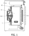
FIG. 1 is a schematic structural view of the drum washing machine of the present disclosure; -
FIG. 2 is a schematic view of the lifting device of the present disclosure; -
FIG. 3 is a cross-sectional view taken along line A-A inFIG. 2 ; and -
FIG. 4 is a schematic view of the connection between the balancing rod, the valve body guide column and the counterweight guide column of the lifting device of the present disclosure. - 1: lifting device; 11: lifting rib shell; 111: water passing hole; 12: bracket; 121: first through hole; 122: second through hole; 123: support seat; 1231: middle rotating shaft; 2: centrifugal assembly; 21: valve body guide column; 211: second connecting lug; 212: second sliding rod; 213: second boss; 21 a: first end of valve body guide column; 21b: second end of valve body guide column; 22: valve core; 221: sealing member; 2211: annular sealing rib; 23: counterweight guide column; 23a: first end of counterweight guide column; 23b: second end of counterweight guide column; 231: first connecting lug; 232: first sliding rod; 233: boss; 24: counterweight member; 25: balancing rod; 251: first rotating shaft; 2511: first rotating shaft hole; 252: second rotating shaft; 2521: second rotating shaft hole; 25a: first end of balancing rod; 25b: second end of balancing rod; 26: elastic member; A: size of counterweight member; B: size of first through hole; C: size of valve core; D: size of second through hole; 3: washing machine; 31: inner cylinder; 311: door; 312: water inlet; 32: outer cylinder:
- Preferred embodiments of the present disclosure will be described below with reference to the accompanying drawings. It should be understood by those skilled in the art that these following embodiments are only used to explain the technical principle of the present disclosure, and are not intended to limit the scope of protection of the present disclosure. Those skilled in the art can make adjustments to them as required for adapting to specific application scenes.
- It should be noted that in the description of the present disclosure, terms indicating directional or positional relationships, such as "upper", "lower", "left", "right", "vertical", "horizontal", "inner", "outer" and the like, are based on the directional or positional relationships shown in the accompanying drawings. They are only used for ease of description, and do not indicate or imply that the device or element must have a specific orientation, or must be constructed or operated in a specific orientation; therefore, they should not be considered as limitations to the present disclosure. In addition, terms "first" and "second" are only used for descriptive purpose, and should not be understood as indicating or implying relative importance.
- In addition, it should also be noted that in the description of the present disclosure, unless otherwise clearly specified and defined, terms "install", "communicate" and "connect" should be understood in a broad sense; for example, the connection may be a fixed connection, or a detachable connection, or an integral connection; it may be a mechanical connection, or an electrical connection; it may be a direct connection, or an indirect connection implemented through an intermediate medium, or internal communication between two elements. For those skilled in the art, the specific meaning of the above terms in the present disclosure can be interpreted according to specific situations.
- As shown in
FIGS. 2-4 , in order to solve the problem of reduced service life caused by unreasonable arrangement of the centrifugal assembly in the lifting device of existing drum washing machines, thelifting device 1 for a drum washing machine 3 of the present disclosure includes a housing with a cavity structure; as shown inFIG. 3 , the housing includes a cover shapedlifting rib shell 11, and abracket 12 arranged at an opening of thelifting rib shell 11. Acentrifugal assembly 2 is arranged inside the cavity structure. Thecentrifugal assembly 2 includes a valvebody guide column 21, avalve core 22, acounterweight guide column 23, acounterweight member 24, a balancing rod 25, and anelastic member 26. A middle part of the balancing rod 25 is pivotally connected inside the housing, and afirst end 25a of the balancing rod is hinged to afirst end 23a of the counterweight guide column through a first rotating shaft 251 and a first rotatingshaft hole 2511. Asecond end 23b of the counterweight guide column is connected to thecounterweight member 24 after passing through a first throughhole 121 on the housing, and thecounterweight guide column 23 is slidably arranged in the first throughhole 121. Theelastic member 26 is arranged between thecounterweight guide column 23 and the housing, and is used to reset the position of thecounterweight member 24. Asecond end 25b of the balancing rod is hinged to afirst end 21a of the valve body guide column through a second rotatingshaft 252 and a second rotatingshaft hole 2521. Asecond end 21b of the valve body guide column is connected to thevalve core 22 after passing through a second through hole 122 on the housing. The valvebody guide column 21 is slidably arranged in the second through hole 122, and the first throughhole 121 and the second through hole 122 are arranged on thebracket 12. As shown inFIG. 4 , preferably, thecounterweight guide column 23 includes a first connectinglug 231 and a first slidingrod 232 arranged on the first connectinglug 231. The first end of the balancing rod 25 is hinged to the first connectinglug 231 through the first rotating shaft 251 and the first rotatingshaft hole 2511. Aboss 233 is provided between the first connectinglug 231 and the first slidingrod 232. Theelastic member 26 is a spring, which is sleeved on the first slidingrod 232. One end of the spring abuts against theboss 233, and the other end of the spring abuts against an inner surface of thebracket 12. Of course, theelastic member 26 can also be another elastic member, such as a leaf spring, an elastic rod, etc. Preferably, the first slidingrod 232 is threaded with thecounterweight member 24, and thecounterweight member 24 abuts against an outer surface of thebracket 12. In addition, as shown inFIG. 3 , a size A of thecounterweight member 24 is larger than a size B of the first throughhole 121, and a size C of thevalve core 22 is larger than a size D of the second through hole 122. As shown inFIG. 4 , the valvebody guide column 21 includes a second connectinglug 211 and a second slidingrod 212 arranged on the second connectinglug 211. Thesecond end 25b of the balancing rod is hinged to the second connectinglug 211 through the second rotatingshaft 252 and the second rotatingshaft hole 2521. In addition, the valvebody guide column 21 can also have a structure similar to that of thecounterweight guide column 23, that is, the valvebody guide column 21 can also include asecond boss 213 as shown inFIG. 3 . Thevalve core 22 is detachably connected to the second slidingrod 212, and a sealingmember 221 is also provided at the top of thevalve core 22. Anannular sealing rib 2211 is also provided at the bottom of the sealingmember 221. Asupport seat 123 is provided on thebracket 12, and a middle part of the balancing rod 25 is pivotally connected to thesupport seat 123 through a middlerotating shaft 1231. As shown inFIGS. 2 and 3 ,water passing holes 111 are provide on the liftingrib shell 11. - As shown in
FIG. 1 , the present disclosure also provides a drum washing machine 3, which includes anouter cylinder 32, and aninner cylinder 31 that is rotatably arranged inside theouter cylinder 32; theinner cylinder 31 is provided with a clothing inlet that cooperates with adoor 311 of the washing machine 3, awater inlet 312 connected to a water inflow pipe, and a water outlet; thelifting device 1 for the drum washing machine 3 according to any of the above embodiments is provided on the water outlet, and thevalve core 22 of thelifting device 1 is arranged at the water outlet, so that when thedoor 311 is closed, thewater inlet 32 is closed and thevalve core 22 blocks the water outlet, theinner cylinder 31 is a closed chamber, and when thedoor 311 is closed, the water inlet 312 (not shown) is closed and thevalve core 22 disengages from the water outlet, theinner cylinder 31 can drain water normally. - When the drum washing machine 3 of the present disclosure is in a rinsing or washing program stage, the
inner cylinder 31 rotates at a low speed, and the rotational speed of theinner cylinder 31 of the washing machine 3 is controlled at V<V0, where V0 is the speed at which theinner cylinder 31 drives thecentrifugal assembly 2 to just open the water outlet during the rotation process. At this time, the force received by thecentrifugal assembly 2 is not enough to make it disengage from the water outlet, and the clothing is rinsed or washed normally in the completely sealedinner cylinder 31. After the rinsing or washing program is completed, the washing machine 3 enters a spinning program. During the spinning process of the washing machine 3, theinner cylinder 31 rotates at a high speed, and the rotational speed V of theinner cylinder 31 of the washing machine 3 is controlled to be V≥V0. At this time, thecentrifugal assembly 2 disengages from the water outlet under the action of centrifugal force. Theinner cylinder 31 maintains the rotational speed V for a period of time until the water in theinner cylinder 31 is completely discharged. Then, the spinning program of the washing machine 3 ends, theinner cylinder 31 stops rotating, and thecentrifugal assembly 2 blocks the water outlet again. At this time, the washing machine 3 is controlled to enter the next program. - The above arrangement has the following advantages: the
centrifugal assembly 2 is provided inside thelifting device 1, the middlerotating shaft 1231 at the middle part of the balancing rod 25 is used as a fixed shaft, and thesupport seat 123 fixes the middlerotating shaft 1231 on thebracket 12, so that thecounterweight guide column 23 and the valvebody guide column 21 hinged at both ends of the balancing rod 25 respectively can perform a lever motion. The first connectinglug 231 at thefirst end 23a of the counterweight guide column is connected to thefirst end 25a of the balancing rod, and the second connectinglug 211 at thefirst end 21a of the valve body guide column is connected to thesecond end 25b of the balancing rod. The design of the connecting lugs makes the connection structure less prone to wear and failure. Thecounterweight member 24 is provided at thesecond end 23b of the counterweight guide column, so that the valvebody guide column 21 can drive thevalve core 22 to disengage from the water outlet. A spring is provided on the inner surface of thebracket 12 at the top of thecounterweight member 24, and the spring can provide a pre-pressure for thevalve core 22. Under the action of the spring which simultaneously exerts a pressure to thebracket 12 and theboss 233, thecounterweight member 24 abuts against the outer surface of thebracket 12 under the action of the force of the spring, and at the same time, the force received by theboss 233 is transmitted to thesecond end 25b of the balancing rod, and then to thesecond end 21b of the valve body guide column, ultimately tightly sealing the sealingmember 221 located at the bottom of thevalve core 22 at the water outlet by the valvebody guide column 21. When the washing machine 3 is in a spinning mode, theinner cylinder 31 rotates at a high speed. When the centrifugal force between the valvebody guide column 21 and thevalve core 22 is larger than the pressure provided by the spring, the valvebody guide column 21 moves in a direction toward an axial center theinner cylinder 31 until the sealingmember 221 at the bottom of thevalve core 22 disengages from the water outlet to achieve drainage of the washing machine 3. The first throughhole 121 and the second through hole 122 on thebracket 12 provide a space for the up and down movement of thecounterweight guide column 23 and the valvebody guide column 21. Meanwhile, in order to prevent thecounterweight guide column 23 and the valvebody guide column 21 from disengaging from thebracket 12 during the movement, which may cause thecentrifugal assembly 2 to fail and result in ineffective blocking of the water outlet, the size A of thecounterweight member 24 is set to be larger than the size B of the first throughhole 121, and the size C of thevalve core 22 is set to be larger than the size D of the second through hole 122. This setting can also ensure that thevalve core 22 operates within the range of motion specified in the present disclosure, increasing safety and effectiveness during use. The liftingrib shell 11 is provided with water passing holes 111. When the washing machine 3 is in a washing mode, if thelifting device 1 is located at an upper part of theinner cylinder 31, the water in the cavity of thelifting device 1 sprays downward through the water passing holes 111. When the washing machine 3 is in a drainage mode, the water in theinner cylinder 31 enters thelifting device 1 through thewater passing holes 111 and is finally discharged from the water outlet. By connecting the first slidingrod 232 of thecounterweight guide column 23 with thecounterweight member 24 through threads, the magnitude of the pre-pressure of the spring exerted on thevalve core 22 can be adjusted. When thecounterweight member 24 is connected to the middle part of the first slidingrod 232 through threads, the distance between thebracket 12 and theboss 233 becomes smaller, and the pressure exerted on the spring is larger. Therefore, the pressure transmitted to thevalve core 22 is also larger, and the sealingmember 221 blocks the water outlet tightly. When thecounterweight member 24 is connected to the bottom of the first slidingrod 232 through threads, the distance between thebracket 12 and theboss 233 becomes larger, and the pressure exerted on the spring is smaller. At this time, the pressure transmitted to thevalve core 22 is smaller, and the sealingmember 221 blocks the water outlet loosely. The way of connecting thecounterweight member 24 with thecounterweight guide column 23 through threads can realize the adjustment of the blocking degree of the water outlet by adjusting thecounterweight member 24. - The
inner cylinder 31 of the drum washing machine 3 of the present disclosure is only provided with thewater inlet 312, the water outlet, and the clothing inlet. There is no need to fill the washing and rinsing water between the inner cylinder and theouter cylinder 32 before and during the washing process, which greatly reduces the amount of washing water of the washing machine 3 and also avoids the possibility of dirt adhesion between the inner cylinder and theouter cylinder 32. - As shown in
FIG. 3 , in a possible implementation, thecounterweight member 24 and thecounterweight guide column 23 are separately arranged or integrally formed, and the valvebody guide column 21 and thevalve core 22 are separately arranged or integrally formed. The detachable connection can be realized through threaded connection or through snap-fit connection. - The above arrangement has the following advantages: as shown in
FIG. 3 , the valvebody guide column 21 and thevalve core 22 are detachably connected through threads, and thecounterweight member 24 and thecounterweight guide column 23 are detachably connected through threads. This detachable connection can facilitate replacement of parts, and if one of the parts is damaged during use, this detachable connection can prevent the replacement of this part and all mating parts thereof. The detachable connection also includes snap-fit connection (not shown in the drawings). By integrally forming thecounterweight member 24 and thecounterweight guide column 23, and integrally forming the valvebody guide column 21 and thevalve core 22, the number of parts can be reduced and the assembly difficulty can be lower. - In summary, the
centrifugal assembly 2 is provided inside thelifting device 1, and the middlerotating shaft 1231 at the middle part of the balancing rod 25 is used as a fixed shaft, so that thecounterweight guide column 23 and the valvebody guide column 21 hinged at both ends of the balancing rod 25 respectively can perform a lever motion. Thecounterweight member 24 provided at thesecond end 23b of the counterweight guide column can make the valvebody guide column 21 drive thevalve core 22 to disengage from the water outlet. A spring is provided on the inner surface of thebracket 12 at the top of thecounterweight member 24, and the spring can provide a pre-pressure for thevalve core 22, ultimately tightly sealing the sealingmember 221 located at the bottom of thevalve core 22 at the water outlet by the valvebody guide column 21. When the washing machine 3 is in the spinning mode, if the centrifugal force between the valvebody guide column 21 and thevalve core 22 is larger than the pressure provided by the spring, the valvebody guide column 21 moves in a direction toward an axial center theinner cylinder 31 until the sealingmember 221 at the bottom of thevalve core 22 disengages from the water outlet to achieve drainage of the washing machine 3. In order to prevent thecounterweight guide column 23 and the valvebody guide column 21 from disengaging from thebracket 12 during the movement, the size A of thecounterweight member 24 is set to be larger than the size B of the first throughhole 121, and the size C of thevalve core 22 is set to be larger than the size D of the second through hole 122. By connecting the first slidingrod 232 of thecounterweight guide column 23 with thecounterweight member 24 through threads, the magnitude of the pre-pressure of the spring exerted on thevalve core 22 can be adjusted. When thecounterweight member 24 is connected to the middle part of the first slidingrod 232, the pressure exerted on the spring becomes larger. Therefore, the pressure transmitted to thevalve core 22 is also larger, and the sealingmember 221 blocks the water outlet tightly. When thecounterweight member 24 is connected to the bottom of the first slidingrod 232, the pressure exerted on the spring becomes smaller. At this time, the pressure transmitted to thevalve core 22 is smaller, and the sealingmember 221 blocks the water outlet loosely, ultimately realizing the adjustment of the blocking degree of the water outlet by adjusting thecounterweight member 24. - It should be noted that the above embodiments are only used to illustrate the principles of the present disclosure, and are not intended to limit the scope of protection of the present disclosure. Without departing from the principles of the present disclosure, those skilled in the art can adjust the above structures so that the present disclosure can be applied to more specific application scenes.
- Hitherto, the technical solutions of the present disclosure have been described in connection with the preferred embodiments shown in the accompanying drawings, but it is easily understood by those skilled in the art that the scope of protection of the present disclosure is obviously not limited to these specific embodiments. Without departing from the principles of the present disclosure, those skilled in the art can make equivalent changes or replacements to relevant technical features, and all the technical solutions after these changes or replacements will fall within the scope of protection of the present disclosure.
Claims (10)
- A lifting device for a drum washing machine, wherein the lifting device comprises a housing with a cavity structure; a centrifugal assembly is arranged inside the cavity structure, and the centrifugal assembly comprises a valve body guide column, a valve core, a counterweight guide column, a counterweight member, a balancing rod, and an elastic member;a middle part of the balancing rod is pivotally connected inside the housing;a first end of the balancing rod is hinged to a first end of the counterweight guide column, a second end of the counterweight guide column is connected to the counterweight member after passing through a first through hole on the housing, and the counterweight guide column is slidably arranged in the first through hole;the elastic member is arranged between the counterweight guide column and the housing, and is used to reset the position of the counterweight member;a second end of the balancing rod is hinged to a first end of the valve body guide column, a second end of the valve body guide column is connected to the valve core after passing through a second through hole on the housing, and the valve body guide column is slidably arranged in the second through hole.
- The lifting device for a drum washing machine according to claim 1, wherein the housing comprises a cover shaped lifting rib shell and a bracket arranged at an opening of the lifting rib shell, and the first through hole and the second through hole are arranged on the bracket.
- The lifting device for a drum washing machine according to claim 2, wherein the counterweight guide column comprises a first connecting lug and a first sliding rod arranged on the first connecting lug; the first end of the balancing rod is hinged to the first connecting lug, and a boss is arranged between the first connecting lug and the first sliding rod; the elastic member is a spring, which is sleeved on the first sliding rod; one end of the spring is abuts against the boss, and the other end of the spring abuts against an inner surface of the bracket.
- The lifting device for a drum washing machine according to claim 3, wherein the first sliding rod is threaded with the counterweight member, and the counterweight member abuts against an outer surface of the bracket.
- The lifting device for a drum washing machine according to claim 1, wherein a size of the counterweight member is larger than a size of the first through hole, and/or a size of the valve core is larger than a size of the second through hole.
- The lifting device for a drum washing machine according to claim 2, wherein the valve body guide column comprises a second connecting lug and a second sliding rod arranged on the second connecting lug; the second end of the balancing rod is hinged to the second connecting lug, the valve core is detachably connected to the second sliding rod, and a sealing member is also arranged at the top of the valve core.
- The lifting device for a drum washing machine according to claim 6, wherein an annular sealing rib is also arranged at the bottom of the sealing member.
- The lifting device for a drum washing machine according to claim 2, wherein a support seat is arranged on the bracket, and a middle part of the balancing rod is pivotally connected to the support seat; and/or water passing holes are arranged on the lifting rib shell.
- The lifting device for a drum washing machine according to claim 1, wherein the counterweight member and the counterweight guide column are separately arranged or integrally formed; and/or the valve body guide column and the valve core are separately arranged or integrally formed.
- A drum washing machine, wherein the drum washing machine comprises an outer cylinder, and an inner cylinder that is rotatably arranged inside the outer cylinder; the inner cylinder is provided with a clothing inlet that cooperates with a door of the washing machine, a water inlet connected to a water inflow pipe, and a water outlet; the lifting device for a drum washing machine according to any one of claims 1-9 is provided on the water outlet, and the valve core of the lifting device is arranged at the water outlet, so that when the door is closed, the water inlet is closed and the valve core blocks the water outlet, the inner cylinder is a closed chamber, and when the door is closed, the water inlet is closed and the valve core disengages from the water outlet, the inner cylinder can drain water normally.
Applications Claiming Priority (2)
| Application Number | Priority Date | Filing Date | Title |
|---|---|---|---|
| CN202210254090.1A CN116791326A (en) | 2022-03-15 | 2022-03-15 | Lifting device for drum washing machine and drum washing machine |
| PCT/CN2023/078904 WO2023174052A1 (en) | 2022-03-15 | 2023-03-01 | Lift device for front loading washing machine and front loading washing machine |
Publications (4)
| Publication Number | Publication Date |
|---|---|
| EP4495313A1 true EP4495313A1 (en) | 2025-01-22 |
| EP4495313A4 EP4495313A4 (en) | 2025-05-14 |
| EP4495313B1 EP4495313B1 (en) | 2025-12-10 |
| EP4495313C0 EP4495313C0 (en) | 2025-12-10 |
Family
ID=88022319
Family Applications (1)
| Application Number | Title | Priority Date | Filing Date |
|---|---|---|---|
| EP23769560.6A Active EP4495313B1 (en) | 2022-03-15 | 2023-03-01 | Lift device for front loading washing machine and front loading washing machine |
Country Status (4)
| Country | Link |
|---|---|
| US (1) | US20250376797A1 (en) |
| EP (1) | EP4495313B1 (en) |
| CN (1) | CN116791326A (en) |
| WO (1) | WO2023174052A1 (en) |
Family Cites Families (11)
| Publication number | Priority date | Publication date | Assignee | Title |
|---|---|---|---|---|
| JPH08155190A (en) * | 1994-12-05 | 1996-06-18 | Sharp Corp | Washing machine |
| CN105986430B (en) * | 2015-02-13 | 2019-08-27 | 青岛海尔洗衣机有限公司 | Drainage structure of a washing machine |
| CN105951348B (en) * | 2016-05-26 | 2018-04-24 | 张久军 | Roller washing machine and its high-efficient washing, furnace drying method |
| CN109423800B (en) * | 2017-08-31 | 2022-04-22 | 青岛海尔洗衣机有限公司 | Washing machine |
| CN109868614B (en) * | 2017-12-01 | 2022-07-01 | 青岛海尔洗衣机有限公司 | a washing machine |
| CN111485374B (en) * | 2019-01-25 | 2022-07-19 | 青岛海尔洗衣机有限公司 | Lifting device applied to drum washing machine and drum washing machine |
| CN111485378B (en) * | 2019-01-25 | 2022-08-30 | 青岛海尔洗衣机有限公司 | Drum washing machine |
| CN112095275B (en) * | 2019-05-31 | 2023-11-07 | 无锡小天鹅电器有限公司 | Laundry treating apparatus, control method thereof, and control device thereof |
| CN113106703B (en) * | 2020-01-09 | 2024-07-23 | 重庆海尔滚筒洗衣机有限公司 | Clothes lifting device for washing machine and drum washing machine |
| CN213681365U (en) * | 2020-08-25 | 2021-07-13 | 无锡小天鹅电器有限公司 | Bucket assembly and clothes treatment equipment with same |
| CN112538716B (en) * | 2020-11-10 | 2025-06-20 | 佛山市顺德海尔电器有限公司 | Washing machine and control method thereof |
-
2022
- 2022-03-15 CN CN202210254090.1A patent/CN116791326A/en active Pending
-
2023
- 2023-03-01 US US18/847,107 patent/US20250376797A1/en active Pending
- 2023-03-01 WO PCT/CN2023/078904 patent/WO2023174052A1/en not_active Ceased
- 2023-03-01 EP EP23769560.6A patent/EP4495313B1/en active Active
Also Published As
| Publication number | Publication date |
|---|---|
| WO2023174052A1 (en) | 2023-09-21 |
| EP4495313B1 (en) | 2025-12-10 |
| EP4495313C0 (en) | 2025-12-10 |
| CN116791326A (en) | 2023-09-22 |
| US20250376797A1 (en) | 2025-12-11 |
| EP4495313A4 (en) | 2025-05-14 |
Similar Documents
| Publication | Publication Date | Title |
|---|---|---|
| JP7012095B2 (en) | washing machine | |
| EP1347138A2 (en) | Apparatus for opening and closing door | |
| CN107407115B (en) | Door hinge components | |
| CN111485392A (en) | Lifting device applied to drum washing machine and drum washing machine | |
| WO2022028442A1 (en) | Valve element structure, centrifugal valve and washing machine | |
| KR20250089456A (en) | 360-degree rotational cam hydraulic door closer for narrow frame door | |
| EP4089225A1 (en) | Laundry lifting device for washing machine, and drum washing machine | |
| US20250376797A1 (en) | Lift device for front loading washing machine and front loading washing machine | |
| EP4353895A1 (en) | Centrifugal drainage mechanism and laundry lifting device for washing machine, and washing machine | |
| CN102011423B (en) | Double gear drain valve for water tank | |
| CN110594481B (en) | Automatic flow control valve | |
| CN217634152U (en) | Valve opening and closing control device | |
| CN208309211U (en) | Drum mechanism and washing machine having the same | |
| CN209976402U (en) | Connecting structure of upper cover of vacuum packaging machine | |
| CN110805731A (en) | A wide-flow safety intelligent gas meter motor valve | |
| KR100497144B1 (en) | A damper device for both sides | |
| CN115478415B (en) | Inner barrel flange assembly and washing machine | |
| CN114763655A (en) | Washing machine drain valve assembly and washing machine | |
| CN110552161A (en) | Washing machine spin tub and washing machine | |
| CN210318686U (en) | Exhaust valve | |
| JP7240488B2 (en) | Drainage device for washing machine, washing machine and control method thereof | |
| EP4509649A1 (en) | Washing apparatus | |
| CN115478416B (en) | Centrifugal drainage device and washing machine | |
| CN222119693U (en) | Water level switch for washing machine | |
| EP1518956B1 (en) | Household electrical appliance provided with door for closing an internal chamber |
Legal Events
| Date | Code | Title | Description |
|---|---|---|---|
| STAA | Information on the status of an ep patent application or granted ep patent |
Free format text: STATUS: THE INTERNATIONAL PUBLICATION HAS BEEN MADE |
|
| PUAI | Public reference made under article 153(3) epc to a published international application that has entered the european phase |
Free format text: ORIGINAL CODE: 0009012 |
|
| STAA | Information on the status of an ep patent application or granted ep patent |
Free format text: STATUS: REQUEST FOR EXAMINATION WAS MADE |
|
| 17P | Request for examination filed |
Effective date: 20240912 |
|
| AK | Designated contracting states |
Kind code of ref document: A1 Designated state(s): AL AT BE BG CH CY CZ DE DK EE ES FI FR GB GR HR HU IE IS IT LI LT LU LV MC ME MK MT NL NO PL PT RO RS SE SI SK SM TR |
|
| STAA | Information on the status of an ep patent application or granted ep patent |
Free format text: STATUS: EXAMINATION IS IN PROGRESS |
|
| A4 | Supplementary search report drawn up and despatched |
Effective date: 20250416 |
|
| RIC1 | Information provided on ipc code assigned before grant |
Ipc: D06F 23/02 20060101ALN20250410BHEP Ipc: D06F 39/08 20060101ALN20250410BHEP Ipc: D06F 37/06 20060101AFI20250410BHEP |
|
| 17Q | First examination report despatched |
Effective date: 20250428 |
|
| DAV | Request for validation of the european patent (deleted) | ||
| DAX | Request for extension of the european patent (deleted) | ||
| GRAP | Despatch of communication of intention to grant a patent |
Free format text: ORIGINAL CODE: EPIDOSNIGR1 |
|
| STAA | Information on the status of an ep patent application or granted ep patent |
Free format text: STATUS: GRANT OF PATENT IS INTENDED |
|
| RIC1 | Information provided on ipc code assigned before grant |
Ipc: D06F 37/06 20060101AFI20250916BHEP Ipc: D06F 39/08 20060101ALN20250916BHEP Ipc: D06F 23/02 20060101ALN20250916BHEP |
|
| GRAS | Grant fee paid |
Free format text: ORIGINAL CODE: EPIDOSNIGR3 |
|
| INTG | Intention to grant announced |
Effective date: 20251001 |
|
| GRAA | (expected) grant |
Free format text: ORIGINAL CODE: 0009210 |
|
| STAA | Information on the status of an ep patent application or granted ep patent |
Free format text: STATUS: THE PATENT HAS BEEN GRANTED |
|
| AK | Designated contracting states |
Kind code of ref document: B1 Designated state(s): AL AT BE BG CH CY CZ DE DK EE ES FI FR GB GR HR HU IE IS IT LI LT LU LV MC ME MK MT NL NO PL PT RO RS SE SI SK SM TR |
|
| REG | Reference to a national code |
Ref country code: CH Ref legal event code: F10 Free format text: ST27 STATUS EVENT CODE: U-0-0-F10-F00 (AS PROVIDED BY THE NATIONAL OFFICE) Effective date: 20251210 Ref country code: GB Ref legal event code: FG4D |
|
| REG | Reference to a national code |
Ref country code: DE Ref legal event code: R096 Ref document number: 602023009631 Country of ref document: DE Ref country code: IE Ref legal event code: FG4D |
|
| U01 | Request for unitary effect filed |
Effective date: 20251229 |
|
| U07 | Unitary effect registered |
Designated state(s): AT BE BG DE DK EE FI FR IT LT LU LV MT NL PT RO SE SI Effective date: 20260109 |
|
| PG25 | Lapsed in a contracting state [announced via postgrant information from national office to epo] |
Ref country code: ES Free format text: LAPSE BECAUSE OF FAILURE TO SUBMIT A TRANSLATION OF THE DESCRIPTION OR TO PAY THE FEE WITHIN THE PRESCRIBED TIME-LIMIT Effective date: 20251210 |
|
| PG25 | Lapsed in a contracting state [announced via postgrant information from national office to epo] |
Ref country code: NO Free format text: LAPSE BECAUSE OF FAILURE TO SUBMIT A TRANSLATION OF THE DESCRIPTION OR TO PAY THE FEE WITHIN THE PRESCRIBED TIME-LIMIT Effective date: 20260310 |
|
| PG25 | Lapsed in a contracting state [announced via postgrant information from national office to epo] |
Ref country code: HR Free format text: LAPSE BECAUSE OF FAILURE TO SUBMIT A TRANSLATION OF THE DESCRIPTION OR TO PAY THE FEE WITHIN THE PRESCRIBED TIME-LIMIT Effective date: 20251210 |
|
| PG25 | Lapsed in a contracting state [announced via postgrant information from national office to epo] |
Ref country code: RS Free format text: LAPSE BECAUSE OF FAILURE TO SUBMIT A TRANSLATION OF THE DESCRIPTION OR TO PAY THE FEE WITHIN THE PRESCRIBED TIME-LIMIT Effective date: 20260310 |
|
| U20 | Renewal fee for the european patent with unitary effect paid |
Year of fee payment: 4 Effective date: 20260326 |
|
| PG25 | Lapsed in a contracting state [announced via postgrant information from national office to epo] |
Ref country code: SM Free format text: LAPSE BECAUSE OF FAILURE TO SUBMIT A TRANSLATION OF THE DESCRIPTION OR TO PAY THE FEE WITHIN THE PRESCRIBED TIME-LIMIT Effective date: 20251210 |
|
| PG25 | Lapsed in a contracting state [announced via postgrant information from national office to epo] |
Ref country code: PL Free format text: LAPSE BECAUSE OF FAILURE TO SUBMIT A TRANSLATION OF THE DESCRIPTION OR TO PAY THE FEE WITHIN THE PRESCRIBED TIME-LIMIT Effective date: 20251210 |
|
| PG25 | Lapsed in a contracting state [announced via postgrant information from national office to epo] |
Ref country code: IS Free format text: LAPSE BECAUSE OF FAILURE TO SUBMIT A TRANSLATION OF THE DESCRIPTION OR TO PAY THE FEE WITHIN THE PRESCRIBED TIME-LIMIT Effective date: 20260410 |
|
| PG25 | Lapsed in a contracting state [announced via postgrant information from national office to epo] |
Ref country code: CZ Free format text: LAPSE BECAUSE OF FAILURE TO SUBMIT A TRANSLATION OF THE DESCRIPTION OR TO PAY THE FEE WITHIN THE PRESCRIBED TIME-LIMIT Effective date: 20251210 |
|
| PG25 | Lapsed in a contracting state [announced via postgrant information from national office to epo] |
Ref country code: SK Free format text: LAPSE BECAUSE OF FAILURE TO SUBMIT A TRANSLATION OF THE DESCRIPTION OR TO PAY THE FEE WITHIN THE PRESCRIBED TIME-LIMIT Effective date: 20251210 |