EP4495057A2 - System for decomposing ammonia and method of decomposing ammonia - Google Patents
System for decomposing ammonia and method of decomposing ammonia Download PDFInfo
- Publication number
- EP4495057A2 EP4495057A2 EP24187549.1A EP24187549A EP4495057A2 EP 4495057 A2 EP4495057 A2 EP 4495057A2 EP 24187549 A EP24187549 A EP 24187549A EP 4495057 A2 EP4495057 A2 EP 4495057A2
- Authority
- EP
- European Patent Office
- Prior art keywords
- cracker
- ammonia
- fuel cell
- pipe
- bypass line
- Prior art date
- Legal status (The legal status is an assumption and is not a legal conclusion. Google has not performed a legal analysis and makes no representation as to the accuracy of the status listed.)
- Pending
Links
Images



Classifications
-
- H—ELECTRICITY
- H01—ELECTRIC ELEMENTS
- H01M—PROCESSES OR MEANS, e.g. BATTERIES, FOR THE DIRECT CONVERSION OF CHEMICAL ENERGY INTO ELECTRICAL ENERGY
- H01M8/00—Fuel cells; Manufacture thereof
- H01M8/06—Combination of fuel cells with means for production of reactants or for treatment of residues
- H01M8/0606—Combination of fuel cells with means for production of reactants or for treatment of residues with means for production of gaseous reactants
-
- B—PERFORMING OPERATIONS; TRANSPORTING
- B01—PHYSICAL OR CHEMICAL PROCESSES OR APPARATUS IN GENERAL
- B01J—CHEMICAL OR PHYSICAL PROCESSES, e.g. CATALYSIS OR COLLOID CHEMISTRY; THEIR RELEVANT APPARATUS
- B01J19/00—Chemical, physical or physico-chemical processes in general; Their relevant apparatus
- B01J19/0006—Controlling or regulating processes
- B01J19/0013—Controlling the temperature of the process
-
- C—CHEMISTRY; METALLURGY
- C01—INORGANIC CHEMISTRY
- C01B—NON-METALLIC ELEMENTS; COMPOUNDS THEREOF; METALLOIDS OR COMPOUNDS THEREOF NOT COVERED BY SUBCLASS C01C
- C01B3/00—Hydrogen; Gaseous mixtures containing hydrogen; Separation of hydrogen from mixtures containing it; Purification of hydrogen; Reversible storage of hydrogen
- C01B3/02—Production of hydrogen; Production of gaseous mixtures containing hydrogen
- C01B3/04—Production of hydrogen; Production of gaseous mixtures containing hydrogen by decomposition of inorganic compounds
- C01B3/047—Decomposition of ammonia
-
- H—ELECTRICITY
- H01—ELECTRIC ELEMENTS
- H01M—PROCESSES OR MEANS, e.g. BATTERIES, FOR THE DIRECT CONVERSION OF CHEMICAL ENERGY INTO ELECTRICAL ENERGY
- H01M8/00—Fuel cells; Manufacture thereof
- H01M8/04—Auxiliary arrangements, e.g. for control of pressure or for circulation of fluids
- H01M8/04298—Processes for controlling fuel cells or fuel cell systems
-
- H—ELECTRICITY
- H01—ELECTRIC ELEMENTS
- H01M—PROCESSES OR MEANS, e.g. BATTERIES, FOR THE DIRECT CONVERSION OF CHEMICAL ENERGY INTO ELECTRICAL ENERGY
- H01M8/00—Fuel cells; Manufacture thereof
- H01M8/04—Auxiliary arrangements, e.g. for control of pressure or for circulation of fluids
- H01M8/04298—Processes for controlling fuel cells or fuel cell systems
- H01M8/04313—Processes for controlling fuel cells or fuel cell systems characterised by the detection or assessment of variables; characterised by the detection or assessment of failure or abnormal function
-
- H—ELECTRICITY
- H01—ELECTRIC ELEMENTS
- H01M—PROCESSES OR MEANS, e.g. BATTERIES, FOR THE DIRECT CONVERSION OF CHEMICAL ENERGY INTO ELECTRICAL ENERGY
- H01M8/00—Fuel cells; Manufacture thereof
- H01M8/04—Auxiliary arrangements, e.g. for control of pressure or for circulation of fluids
- H01M8/04298—Processes for controlling fuel cells or fuel cell systems
- H01M8/04313—Processes for controlling fuel cells or fuel cell systems characterised by the detection or assessment of variables; characterised by the detection or assessment of failure or abnormal function
- H01M8/0432—Temperature; Ambient temperature
- H01M8/04373—Temperature; Ambient temperature of auxiliary devices, e.g. reformers, compressors, burners
-
- B—PERFORMING OPERATIONS; TRANSPORTING
- B01—PHYSICAL OR CHEMICAL PROCESSES OR APPARATUS IN GENERAL
- B01J—CHEMICAL OR PHYSICAL PROCESSES, e.g. CATALYSIS OR COLLOID CHEMISTRY; THEIR RELEVANT APPARATUS
- B01J2219/00—Chemical, physical or physico-chemical processes in general; Their relevant apparatus
- B01J2219/00049—Controlling or regulating processes
- B01J2219/00051—Controlling the temperature
- B01J2219/00054—Controlling or regulating the heat exchange system
- B01J2219/00056—Controlling or regulating the heat exchange system involving measured parameters
- B01J2219/00058—Temperature measurement
- B01J2219/00063—Temperature measurement of the reactants
-
- B—PERFORMING OPERATIONS; TRANSPORTING
- B01—PHYSICAL OR CHEMICAL PROCESSES OR APPARATUS IN GENERAL
- B01J—CHEMICAL OR PHYSICAL PROCESSES, e.g. CATALYSIS OR COLLOID CHEMISTRY; THEIR RELEVANT APPARATUS
- B01J2219/00—Chemical, physical or physico-chemical processes in general; Their relevant apparatus
- B01J2219/00049—Controlling or regulating processes
- B01J2219/00162—Controlling or regulating processes controlling the pressure
-
- C—CHEMISTRY; METALLURGY
- C01—INORGANIC CHEMISTRY
- C01B—NON-METALLIC ELEMENTS; COMPOUNDS THEREOF; METALLOIDS OR COMPOUNDS THEREOF NOT COVERED BY SUBCLASS C01C
- C01B2203/00—Integrated processes for the production of hydrogen or synthesis gas
- C01B2203/02—Processes for making hydrogen or synthesis gas
- C01B2203/0266—Processes for making hydrogen or synthesis gas containing a decomposition step
-
- C—CHEMISTRY; METALLURGY
- C01—INORGANIC CHEMISTRY
- C01B—NON-METALLIC ELEMENTS; COMPOUNDS THEREOF; METALLOIDS OR COMPOUNDS THEREOF NOT COVERED BY SUBCLASS C01C
- C01B2203/00—Integrated processes for the production of hydrogen or synthesis gas
- C01B2203/04—Integrated processes for the production of hydrogen or synthesis gas containing a purification step for the hydrogen or the synthesis gas
- C01B2203/0415—Purification by absorption in liquids
-
- C—CHEMISTRY; METALLURGY
- C01—INORGANIC CHEMISTRY
- C01B—NON-METALLIC ELEMENTS; COMPOUNDS THEREOF; METALLOIDS OR COMPOUNDS THEREOF NOT COVERED BY SUBCLASS C01C
- C01B2203/00—Integrated processes for the production of hydrogen or synthesis gas
- C01B2203/04—Integrated processes for the production of hydrogen or synthesis gas containing a purification step for the hydrogen or the synthesis gas
- C01B2203/0465—Composition of the impurity
-
- C—CHEMISTRY; METALLURGY
- C01—INORGANIC CHEMISTRY
- C01B—NON-METALLIC ELEMENTS; COMPOUNDS THEREOF; METALLOIDS OR COMPOUNDS THEREOF NOT COVERED BY SUBCLASS C01C
- C01B2203/00—Integrated processes for the production of hydrogen or synthesis gas
- C01B2203/06—Integration with other chemical processes
- C01B2203/066—Integration with other chemical processes with fuel cells
-
- C—CHEMISTRY; METALLURGY
- C01—INORGANIC CHEMISTRY
- C01B—NON-METALLIC ELEMENTS; COMPOUNDS THEREOF; METALLOIDS OR COMPOUNDS THEREOF NOT COVERED BY SUBCLASS C01C
- C01B2203/00—Integrated processes for the production of hydrogen or synthesis gas
- C01B2203/08—Methods of heating or cooling
- C01B2203/0805—Methods of heating the process for making hydrogen or synthesis gas
-
- C—CHEMISTRY; METALLURGY
- C01—INORGANIC CHEMISTRY
- C01B—NON-METALLIC ELEMENTS; COMPOUNDS THEREOF; METALLOIDS OR COMPOUNDS THEREOF NOT COVERED BY SUBCLASS C01C
- C01B2203/00—Integrated processes for the production of hydrogen or synthesis gas
- C01B2203/16—Controlling the process
-
- C—CHEMISTRY; METALLURGY
- C01—INORGANIC CHEMISTRY
- C01B—NON-METALLIC ELEMENTS; COMPOUNDS THEREOF; METALLOIDS OR COMPOUNDS THEREOF NOT COVERED BY SUBCLASS C01C
- C01B2203/00—Integrated processes for the production of hydrogen or synthesis gas
- C01B2203/16—Controlling the process
- C01B2203/1614—Controlling the temperature
- C01B2203/1619—Measuring the temperature
-
- C—CHEMISTRY; METALLURGY
- C01—INORGANIC CHEMISTRY
- C01B—NON-METALLIC ELEMENTS; COMPOUNDS THEREOF; METALLOIDS OR COMPOUNDS THEREOF NOT COVERED BY SUBCLASS C01C
- C01B2203/00—Integrated processes for the production of hydrogen or synthesis gas
- C01B2203/16—Controlling the process
- C01B2203/1628—Controlling the pressure
- C01B2203/1638—Adjusting the pressure
-
- C—CHEMISTRY; METALLURGY
- C01—INORGANIC CHEMISTRY
- C01B—NON-METALLIC ELEMENTS; COMPOUNDS THEREOF; METALLOIDS OR COMPOUNDS THEREOF NOT COVERED BY SUBCLASS C01C
- C01B2203/00—Integrated processes for the production of hydrogen or synthesis gas
- C01B2203/16—Controlling the process
- C01B2203/1685—Control based on demand of downstream process
-
- C—CHEMISTRY; METALLURGY
- C01—INORGANIC CHEMISTRY
- C01B—NON-METALLIC ELEMENTS; COMPOUNDS THEREOF; METALLOIDS OR COMPOUNDS THEREOF NOT COVERED BY SUBCLASS C01C
- C01B2203/00—Integrated processes for the production of hydrogen or synthesis gas
- C01B2203/16—Controlling the process
- C01B2203/1695—Adjusting the feed of the combustion
-
- Y—GENERAL TAGGING OF NEW TECHNOLOGICAL DEVELOPMENTS; GENERAL TAGGING OF CROSS-SECTIONAL TECHNOLOGIES SPANNING OVER SEVERAL SECTIONS OF THE IPC; TECHNICAL SUBJECTS COVERED BY FORMER USPC CROSS-REFERENCE ART COLLECTIONS [XRACs] AND DIGESTS
- Y02—TECHNOLOGIES OR APPLICATIONS FOR MITIGATION OR ADAPTATION AGAINST CLIMATE CHANGE
- Y02E—REDUCTION OF GREENHOUSE GAS [GHG] EMISSIONS, RELATED TO ENERGY GENERATION, TRANSMISSION OR DISTRIBUTION
- Y02E60/00—Enabling technologies; Technologies with a potential or indirect contribution to GHG emissions mitigation
- Y02E60/30—Hydrogen technology
- Y02E60/36—Hydrogen production from non-carbon containing sources, e.g. by water electrolysis
-
- Y—GENERAL TAGGING OF NEW TECHNOLOGICAL DEVELOPMENTS; GENERAL TAGGING OF CROSS-SECTIONAL TECHNOLOGIES SPANNING OVER SEVERAL SECTIONS OF THE IPC; TECHNICAL SUBJECTS COVERED BY FORMER USPC CROSS-REFERENCE ART COLLECTIONS [XRACs] AND DIGESTS
- Y02—TECHNOLOGIES OR APPLICATIONS FOR MITIGATION OR ADAPTATION AGAINST CLIMATE CHANGE
- Y02E—REDUCTION OF GREENHOUSE GAS [GHG] EMISSIONS, RELATED TO ENERGY GENERATION, TRANSMISSION OR DISTRIBUTION
- Y02E60/00—Enabling technologies; Technologies with a potential or indirect contribution to GHG emissions mitigation
- Y02E60/30—Hydrogen technology
- Y02E60/50—Fuel cells
Definitions
- the embodiments of the present disclosure relate generally to a system for decomposing ammonia and a method of decomposing ammonia.
- Load fluctuations may frequently occur in a mobility environment such as a ship or a dump truck. Accordingly, when a feedback logic of an ammonia decomposition reaction in a plant environment such as a chemical plant is directly applied to the mobility environment, an ammonia decomposition ratio may be lowered.
- the ammonia decomposition reaction in a plant-scale environment may not be easily controlled in a load follow operation state such as a rapid acceleration or deceleration, for example, in a ship or a dump truck. Accordingly, a decrease in a power of an entire system or a decrease in a battery performance may be caused.
- a process of decomposing ammonia to produce hydrogen is an endothermic reaction that requires a lot of heat.
- an endothermic reaction may occur at a relatively low temperature when a large amount of ammonia is introduced and an inner temperature of a cracker is rapidly lowered. Accordingly, a hydrogen conversion ratio is lowered and an amount of a residual ammonia may be increased due to an incomplete reaction.
- a system for decomposing ammonia having improved decomposition efficiency.
- an eco-friendly system capable of producing clean energy which utilizes an ammonia decomposition system and an ammonia decomposition method according to embodiments of the present disclosure.
- the bypass line may include a hydrogen supply pipe, and a bypass valve for controlling a hydrogen flow rate in the hydrogen supply pipe.
- the controller is configured to control an operation of the bypass line by opening the bypass valve when the internal temperature of the cracker is less than a preset temperature.
- the controller may be configured to control an operation of the bypass line by opening the bypass valve when the residual ammonia in the cracker is equal to or greater than a preset amount.
- the system may further include a separator that is adapted to transmit hydrogen and nitrogen from hydrogen, nitrogen and the residual ammonia discharged from the discharge pipe of the cracker.
- the system may further include a first valve for controlling a flow rate of ammonia introduced from an absorption pipe of the cracker, and a second valve for controlling a flow rate of hydrogen, nitrogen and the residual ammonia discharged from the discharge pipe of the cracker.
- the controller may be configured to control a pressure and a temperature increase in the cracker by closing at least one of the first valve and the second valve when the residual ammonia in the cracker is greater than a preset amount.
- the controller may be configured to increase the internal pressure of the cracker by the pressing element when the residual ammonia in the cracker is equal to or greater than a preset amount.
- a system for decomposing ammonia includes a cracker adapted to decompose an ammonia feed to generate a decomposition product comprising hydrogen, nitrogen, and residual ammonia and feeding the decomposition product to an absorber; the absorber configured to absorb the residual ammonia from the decomposition product and feeding the remaining mixture of hydrogen, and nitrogen to a fuel cell, the fuel cell configured to react at least a portion of the hydrogen received from the absorber to generate power; a bypass line connecting a pipe that connects the cracker and the fuel cell with a pipe connecting the fuel cell and the heater; a sensor configured to sense an internal temperature of the cracker and transmitting the internal temperature to a controller; and the controller configured to receive the internal temperature of the cracker from the sensor, and controlling an operation of the bypass line based on the internal temperature received from the sensor.
- an ammonia decomposition system includes a bypass line between a cracker and an absorber or between the absorber and a fuel cell, and an operation of the bypass line may be controlled based on a temperature in the cracker and an amount of a residual ammonia.
- the ammonia decomposition system may promote an ammonia decomposition reaction in the cracker by using a valve in the bypass line, a valve in an absorption or discharge pipe of the cracker, a separator adjacent to the discharge pipe of the cracker, etc.
- the same reference numerals refer to the same elements.
- the present disclosure does not describe all elements of the embodiments, and general contents in the technical field to which the present disclosure pertains or repeated contents between embodiments can be omitted.
- the term "part, module, member, block, etc.” used herein may be implemented by a software or a hardware, and according to embodiments, a plurality of the "'part, module, member, block, etc.” may be implemented as a single element, or a single "part, module, member, block, etc.” may include a plurality of elements.
- the recitation includes a case where a member is in contact with another member, and a case where another member is present between the two members.
- each step code is used for convenience of descriptions, and is not intended to limit the order of each step, and each step may be performed differently from the specified order unless a specific order is clearly described herein.
- the device includes all various devices capable of performing arithmetic processing and providing a result to a user.
- the device according to the present disclosure may include all of a computer, a server device and a portable terminal, or may include any one of the forms.
- the computer may include, e.g., a notebook computer, a desktop, a laptop computer, a tablet PC, a slate PC, etc., equipped with a web browser.
- the server device is a server that processes information by communicating with an external device, and may include an application server, a computing server, a database server, a file server, a game server, a mail server, a proxy server, a web server, etc.
- the portable terminal may be a wireless communication device having portability and mobility.
- the portable terminal may include all types of handheld-based wireless communication devices such as a personal communication system (PCS), a global system for mobile communications (GSM), a personal digital cell (PDC), a personal handy phone system (PHS), a personal digital assistant (PDA), an International Mobile Telecommunication (IMT)-2000, Code Division Multiple Access (CDMA)-2000, W-CDMA (W-Code Division Multiple Access), a wireless broadband Internet (WiBro) terminal, a smartphone, etc., and may include wearable devices such as a watch, a ring, a bracelet, an anklet, a necklace, glasses, contact lenses, or a head-mounted-device (HMD).
- PCS personal communication system
- GSM global system for mobile communications
- PDC personal digital cell
- PHS personal handy phone system
- IMT International Mobile Telecommunication
- CDMA Code Division Multiple Access
- W-CDMA W-Code Division Multiple Access
- WiBro wireless broadband Internet
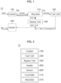
- FIG. 1 is a block diagram of a system for decomposing ammonia in accordance with embodiments of the present disclosure.
- FIG. 2 is a schematic block diagram illustrating components of a system for decomposing ammonia in accordance with embodiments of the present disclosure.
- a system for decomposing ammonia (hereinafter, that may be referred to as an ammonia decomposition system) may be implemented as a bypass ammonia decomposition system.
- an ammonia decomposition system 10 includes a cracker 100, a fuel cell 200, a bypass line 300, a heater 400, an absorber 510 and a sensor 600. Each component/node may exchange data with or from another component/node. Each node may be connected through a network.
- the ammonia decomposition system 10 may receive and decompose ammonia (NH 3 ) through the cracker 100.
- NH 3 ammonia
- an internal temperature of the cracker 100 is temporarily lowered, the ammonia decomposition ratio may be lowered due to a catalyst deactivation or a performance degradation in the cracker 100. Accordingly, an amount of a residual ammonia in the cracker 100 may be relatively increased to result in the reduction of the ammonia decomposition ratio again.
- the cracker 100 may receive ammonia to produce hydrogen (H 2 ), nitrogen (N 2 ), and ammonia (NH 3 ) as a decomposition product.
- the decomposition product (H 2 , N 2 , and residual NH 3 ) from the cracker 100 is fed to an absorber 510.
- the absorber 510 absorbs residual ammonia while the hydrogen and nitrogen are fed to the fuel cell.
- a reaction in which ammonia is decomposed in the ammonia decomposition system 10 is an endothermic reaction. Accordingly, as the ammonia decomposition reaction occurs, a temperature in the ammonia decomposition system 10 may be lowered.
- ammonia decomposition system 10 may reduce the amount of the residual ammonia by continuously promoting the ammonia decomposition reaction.
- the fuel cell 200 may supply nitrogen, and non-converted hydrogen, etc., to the heater 400 before being supplied back to the cracker 100 again. Accordingly, a temperature of the non-converted hydrogen which is relatively higher than the internal temperature of the cracker 100 may induce a temperature increasing effect of the cracker 100. As described above, the ammonia decomposition system 10 may provide the temperature increasing effect by supplementing a temperature decrease due to an imbalance of materials supplied into the cracker 100 and the endothermic reaction.
- a flue gas may be discharged from the heater 400 after the above-described reaction.
- the ammonia decomposition system 10 may include the cracker 100, a controller 110, the fuel cell 200, the bypass line 300, the heater 400, the absorber 510 and the sensor 600. It is noted, however, that the number of and type of elements that may be included in the ammonia decomposition system 10 is not limited thereto.
- the ammonia decomposition system 10 of the present disclosure may include a processing server or a cloud server substantially capable of performing the function of the controller 110 instead of the controller 110.
- the cracker 100 of the ammonia decomposition system 10 may include a reactor.
- the cracker 100 may include the sensor 600 configured to sense the internal temperature of the cracker 100.
- the controller 110 may receive an information on the internal temperature of the cracker 100 from the sensor 600.
- the sensor 600 may sense the amount of the residual ammonia in the cracker.
- the controller 110 may receive a residual ammonia amount information in the cracker 100 from the sensor 600.
- the sensor 600 includes a sensor capable of sensing various types of information (e.g., the internal temperature of the cracker, the amount of the residual ammonia in the cracker, etc.).
- the controller 110 may receive the information sensed by the sensor 600.
- the sensor may be multiple sensors such as, for example, a temperature sensor for sensing an internal temperature of the cracker 100, and a residual ammonia detector for sensing the amount of residual ammonia in the cracker 100.
- the positioning of the sensor 600 may vary depending on the type of the sensor.
- the residual ammonia detector may be positioned at or near an outlet of the cracker 100 leading to a pipe connecting the outlet of the cracker 100 with the absorber 510.
- multiple sensors of the same type may be employed as may be needed.
- an internal temperature of the cracker 100 may be measured at more than one location within the cracker reactor 100.
- the cracker reactor 100 may be of any suitable reactor type, such as, for example, a fixed bed type reactor, a fluidized bed type reactor, or a membrane type reactor.
- the controller 110 may control an operation of the bypass line 300 based on at least one of the temperature information and the residual ammonia information.
- the controller 110 may control an operation of the bypass line 300 such that a bypass valve 310 may be opened when the internal temperature of the cracker 100 is less than a preset temperature. In an embodiment, the controller 110 may control an operation of the bypass line 300 such that the bypass valve 310 may be opened when the residual ammonia in the cracker is greater than or equal to a preset amount. Hence, when the internal temperature of the cracker 100 is less than a preset temperature and/or the residual ammonia in the cracker 100 is greater than or equal to a preset value the bypass line 300 may be opened directing a flow from the absorber 510 with excess ammonia first to the heater 400 and then back to the cracker 100.
- the bypass line 300 may include a hydrogen supply pipe 320 and the bypass valve 310.
- the hydrogen supply pipe 320 may supply hydrogen which is a product of the decomposition reaction of ammonia in the cracker 100.
- the bypass valve 310 may adjust a hydrogen flow rate of the hydrogen supply pipe.
- opening the valve may be an operation of entirely opening the valve. In an embodiment, opening the valve may be an operation of partially opening the valve. In an embodiment, when the bypass valve 310 is opened, the flow to the fuel cell 200 may be blocked.
- opening the valve may be adjusted in a range between a completely closed state and an entirely open state of the valve by the operation of opening the valve.
- the heater 400 may be any suitable type and configuration and may generate flue gas as a byproduct the composition of which may vary depending on the type of the heater and/or the fuel used.
- the heater 400 may pass through from outside the cracker 100 to an inside of the cracker 100, or may extend inside of the cracker 100, or may surround an outside of the cracker 100, or may be adjacent to the cracker 100 to transfer a heat. Accordingly, the heater 400 may ramp the inside of the cracker 100 to additionally induce an endothermic (decomposition) reaction of ammonia in the cracker 100.
- the heater 400 may include at least one pipe.
- the heater 400 may include multiple pipes.
- the controller 110 may control the operation of the bypass line 300 based on the temperature information to heat the cracker 100 through at least one pipe.
- the absorber 510 may absorb the residual ammonia discharged from the cracker 100.
- the absorber 510 may be located between a discharge pipe 150 of the cracker 100 and an absorption (inlet) pipe 210 of the fuel cell 200.
- the absorber 510 may use the discharge pipe 150 of the cracker 100 as an absorption pipe of the absorber 510, and may use the absorption pipe 210 of the fuel cell 200 as a discharge pipe of the absorber 510.
- a storage device may store data supporting various functions of the ammonia decomposition system 10 and a program for the operation of the controller 110.
- the storage device may store input/output data (e.g., an image, a video, etc.).
- the storage device may store an application program or an application driven in the ammonia decomposition system 10, and data and instructions for the operation of the ammonia decomposition system 10.
- At least one of the application programs may be downloaded from an external server through a wireless communication.
- the storage device may include at least one type of storage media selected from a network attached storage (NAS), a flash memory type, a hard disk type, a solid state disk (SSD) type, a silicon disk drive (SSD) type, a multimedia card micro type, a card type memory (e.g., an SD or XD memory, etc.), a random access memory (RAM), a static random access memory (SRAM), a read-only memory (ROM), an electrically erasable programmable read-only memory (EEPROM), a programmable read-only memory (PROM), a magnetic memory, a magnetic disk and an optical disk.
- the storage device may include a database separated from the ammonia decomposition system 10, but which is wire-connected or wireless-connected with the ammonia decomposition system 10.
- the ammonia decomposition system 10 may further include an output element (not illustrated).
- the output element may generate an output related to a visual sense, a hearing sense, or a touch sense, and may include a display device.
- the display device may form a mutual-layered structure with a touch sensor or may be provided as an integral structure with the touch sensor to implement a touch screen.
- the touch screen may be provided as a user input element that provides an input interface between the ammonia decomposition system 10 and the user, and may provide an output interface between the ammonia decomposition system 10 and the user.
- the display device displays (outputs) information processed in the ammonia decomposition system 10.
- the display device may display an execution screen information of the application program (e.g., the application) driven in the ammonia decomposition system 10, or information of a user interface (UI) or graphic user interface (GUI) information according to the execution screen information.
- UI user interface
- GUI graphic user interface
- At least one of described elements may be added or deleted corresponding to the performance of the elements shown in FIG. 2 . Further, it may be easily understood by those of ordinarily skilled in the art that mutual positions of the elements may be changed corresponding to the performance or the structure of the ammonia decomposition system 10. Other elements which are well known in the art may also be included without changing the scope of the present disclosure.
- Each element shown in FIG. 2 may be implemented with a software and/or a hardware such as a field programmable gate array (FPGA) and an application specific integrated circuit (ASIC).
- FPGA field programmable gate array
- ASIC application specific integrated circuit
- FIG. 3 is a simplified flowchart of a method of decomposing ammonia using a bypass line in a load follow state in accordance with embodiments of the present disclosure.
- a controller may receive an internal temperature information of a cracker (e.g., the cracker 100 of FIG. 1 ).
- the controller 110 may receive various information generated by a sensor (e.g., the sensor 600 of FIG. 2 ) included in the cracker 100 to sense various information at the inside of the cracker 100.
- the information received by the controller 110 may include the internal temperature information of the cracker 100.
- the controller 110 may receive the residual ammonia information in the cracker 100.
- the residual ammonia information may include an information on an amount of the residual ammonia remaining as a product after the ammonia reaction in the cracker 100.
- the information received by the controller 110 may include the information on the amount of the residual ammonia in the cracker 100.
- At least a portion of the residual ammonia may be discharged from the cracker 100 through a discharge pipe of the cracker 100, and may be introduced into an absorption pipe of the absorber (e.g., designated as 510 in FIGS. 1 and 2 ).
- the controller 110 may control an operation of the bypass line (e.g., bypass line 300 of FIG. 1 ).
- the controller 110 controls the operation of the bypass line based on at least one of the temperature information and the information on the amount of the residual ammonia in the cracker 100.
- the controller 110 may control the operation of the bypass line 300 to improve an efficiency of the ammonia decomposition reaction in the cracker 100. In some embodiments, the controller 110 may control the operation of the bypass line 300 to increase the internal temperature of the cracker 100. In some embodiments, the controller 110 may control the operation of the bypass line 300 to reduce the amount of the residual ammonia at the inside of the cracker 100.
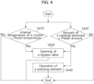
- FIG. 4 is a schematic flowchart of a method of decomposing ammonia using a bypass line in a load follow state in accordance with embodiments of the present disclosure.
- the controller may compare the internal temperature of the cracker (e.g., the cracker 100 of FIG. 1 ) with a preset temperature. For example, the controller 110 may check whether the internal temperature of the cracker 100 is less than or equal to the preset temperature.
- the preset temperature may be stored in the storage device. In some embodiments, the preset temperature may correspond to a critical temperature at which the ammonia decomposition reaction in the cracker 100 may occur.
- the controller 110 may compare the amount of the residual ammonia in the cracker 100 with a preset amount. For example, the controller 110 may check whether the amount of the residual ammonia in the cracker is equal to or greater than the preset amount.
- the preset amount may be stored in the storage device. In some embodiments, the preset amount may correspond to a critical amount of the residual ammonia at which the ammonia decomposition reaction in the cracker 100 may be inhibited.
- the critical amount of the residual ammonia may be an amount at which the ammonia decomposition reaction in the cracker 100 is inhibited when the residual ammonia in the cracker 100 is utilized again as ammonia which is a reactant.
- the critical amount of the residual ammonia may be determined by a ratio of a product to a reactant when an ammonia decomposition productivity in the cracker 100 is converted from a positive (+) state to a negative (-) state.
- the controller 110 may control an operation of the bypass line (e.g., the bypass line 300 of FIG. 2 ) to open a bypass valve.
- the bypass line e.g., the bypass line 300 of FIG. 2
- the controller 110 controls the operation of the bypass line 300 to open the bypass valve.
- the controller 110 may control a degree of opening of the bypass valve stepwise according to a difference between the preset temperature and the internal temperature of the cracker 100.
- the controller 110 controls the operation of the bypass line 300 to open the bypass valve.
- the controller 110 may control the degree of opening of the bypass valve stepwise according to a difference between the preset amount and the amount of the residual ammonia.
- the controller 110 may control the degree of opening of the bypass valve in proportion to a degree of difference of the temperature or the amount.
- the controller 110 may control an operation of a pressing element.
- the pressing element may be a device that controls an internal pressure of the cracker 100 by applying a pressure to the cracker 100.
- the internal temperature of the cracker 100 may be increased by the pressing element.
- the controller 110 may control the operation of the pressing element to increase the pressure in the cracker 100 instead of opening the bypass valve.
- the inside of the cracker 100 may be heated. Accordingly, the ammonia decomposition reaction at the inside of the cracker 100 may be promoted to reduce the amount of the residual ammonia in the cracker 100.
- FIGS. 5A and 5B are schematic block diagrams illustrating a positional modification of a bypass line in accordance with embodiments of the present disclosure.
- the designation of the discharge pipe 150, the absorption pipe 210, the hydrogen supply pipe 320 and the bypass valve 310 in FIG. 1 are omitted for convenience of illustration.
- the ammonia decomposition system 10 may include the bypass line 300 to interact with an operation before a portion of the residual ammonia is introduced into the absorber 510, or an operation after the residual ammonia is absorbed by the absorber 510 and only hydrogen and nitrogen are discharged.
- the bypass line 300 may connect a pipe connecting the cracker 100 and the fuel cell 200, and a pipe connecting the fuel cell 200 and the heater 400 to each other. Accordingly, the controller 110 may supply hydrogen having a relatively high temperature from a hydrogen supply pipe of the bypass line 300 to the heater 400.
- the bypass line 300 may be located between a discharge pipe of the cracker 100 and an absorption pipe of the fuel cell 200.
- the ammonia decomposition system 10 may use the discharge pipe of the cracker 100 as an absorption pipe of the absorber 510, and use the absorption pipe of the fuel cell 200 as a discharge pipe of the absorber 510.
- the bypass line 300 may connect the discharge pipe of the cracker 100 or the absorption pipe of the absorber 510, and the discharge pipe of the fuel cell 200.
- the bypass line 300 may be located between the discharge pipe of the absorber 510 and the absorption pipe of the fuel cell 200.
- the bypass line 300 may connect the discharge pipe of the absorber 510 or the absorption pipe of the fuel cell 200, and the discharge pipe of the fuel cell 200.
- the ammonia decomposition system 10 may control the operation of the bypass line 300 so that hydrogen in the product may bypass without passing through the fuel cell 200.
- the ammonia decomposition system 10 may have a structure capable of utilizing a residual heat of a battery.
- the battery may be, for example, a battery powered by the electricity generated by the fuel cell 200.
- a battery may be adjacent to the heater 400. Accordingly, the ammonia decomposition system 10 may rapidly increase the internal temperature of the cracker 100.
- FIG. 6 is a block diagram of a system for decomposing ammonia including a separator in accordance with embodiments of the present disclosure.
- the ammonia decomposition system 10 may include a separator 700 adjacent to the cracker 100 or coupled to the discharge pipe of the cracker 100.
- the separator 700 may permeate hydrogen and nitrogen among hydrogen, nitrogen and the residual ammonia discharged from the discharge pipe of the cracker 100.
- the separator 700 may inhibit the residual ammonia from flowing into an absorption pipe of absorber 510.
- the separator 700 may include a material that may not permeate or transmit ammonia particles in one direction.
- the separator 700 may have a structure including a membrane filter.
- the ammonia decomposition system 10 may suppress discharge of the residual ammonia to an outside of the separator 700.
- the separator 700 may block permeation of ammonia particles by an electrical reaction.
- the ammonia decomposition system 10 may control an operation of the separator 700 based on the residual ammonia information. For example, if the residual ammonia is detected in the discharge pipe of the cracker 100, the controller 110 may control to block the residual ammonia from flowing through the separator 700 to the abosorber 510 or the bypass line 300.
- FIG. 7 is a block diagram of a system for decomposing ammonia capable of opening and closing a valve in accordance with embodiments of the present disclosure.
- the ammonia decomposition system 10 may include valves 120 and 130 (e.g., a first valve 120 and a second valve 130) adjacent to the cracker 100 or coupled to the absorption pipe and the discharge pipe of the cracker 100.
- valves 120 and 130 e.g., a first valve 120 and a second valve 130
- the first valve 120 may adjust a flow rate of ammonia introduced from the absorption pipe of the cracker 100.
- the second valve 130 may adjust flow rates of hydrogen, nitrogen and the residual ammonia discharged from the discharge pipe of the cracker 100.
- the controller 110 may control an operation of at least one of the first valve 120 and the second valve 130 to control an internal pressure of the cracker 100 and a heating temperature.
- the controller 110 may close at least one of the first valve 120 and the second valve 130.
- the first valve 120 is closed, reaction pressure and temperature in the cracker 100 may be rapidly adjusted.
- the second valve 130 is closed, the reaction pressure and temperature in the cracker 100 may be rapidly adjusted.
- the controller 110 may form an environment capable of promoting an internal reaction of the cracker 100 by combining a closed state or an open state of the first valve 120 and the second valve 130.
- the ammonia decomposition system 10 may control the close/open and closed/opened degree of each valve 120 and 130 by including the first valve 120 and the second valve 130 in the absorption pipe and discharge pipe of the cracker 100.
- the disclosed embodiments may be implemented in the form of a recording medium storing instructions executable by a computer.
- the instructions may be stored in the form of a program code, and a program module may be generated by a processor to perform operations of the disclosed embodiments.
- the recording medium may be implemented in a computer-readable form.
- the computer-readable recording medium includes all types of recording media in which instructions that may be read by a computer are stored.
- the recording medium may include a read only memory (ROM), a random access memory (RAM), a magnetic tape, a magnetic disk, a flash memory, an optical data storage device, etc.
Landscapes
- Chemical & Material Sciences (AREA)
- Engineering & Computer Science (AREA)
- Organic Chemistry (AREA)
- Chemical Kinetics & Catalysis (AREA)
- Life Sciences & Earth Sciences (AREA)
- Manufacturing & Machinery (AREA)
- Sustainable Development (AREA)
- Sustainable Energy (AREA)
- Electrochemistry (AREA)
- General Chemical & Material Sciences (AREA)
- Combustion & Propulsion (AREA)
- Inorganic Chemistry (AREA)
- General Health & Medical Sciences (AREA)
- Health & Medical Sciences (AREA)
- Fuel Cell (AREA)
Abstract
Description
- The embodiments of the present disclosure relate generally to a system for decomposing ammonia and a method of decomposing ammonia.
- Load fluctuations may frequently occur in a mobility environment such as a ship or a dump truck. Accordingly, when a feedback logic of an ammonia decomposition reaction in a plant environment such as a chemical plant is directly applied to the mobility environment, an ammonia decomposition ratio may be lowered.
- Particularly, the ammonia decomposition reaction in a plant-scale environment may not be easily controlled in a load follow operation state such as a rapid acceleration or deceleration, for example, in a ship or a dump truck. Accordingly, a decrease in a power of an entire system or a decrease in a battery performance may be caused.
- A process of decomposing ammonia to produce hydrogen is an endothermic reaction that requires a lot of heat. In the load follow operation, for example, in an environment of a ship or a dump truck, an endothermic reaction may occur at a relatively low temperature when a large amount of ammonia is introduced and an inner temperature of a cracker is rapidly lowered. Accordingly, a hydrogen conversion ratio is lowered and an amount of a residual ammonia may be increased due to an incomplete reaction.
- According to an embodiment of the present disclosure, there is provided a system for decomposing ammonia having improved decomposition efficiency.
- According to another embodiment of the present disclosure, there is provided a method of decomposing ammonia having improved decomposition efficiency.
- According to yet another embodiment of the present disclosure an eco-friendly system capable of producing clean energy is provided which utilizes an ammonia decomposition system and an ammonia decomposition method according to embodiments of the present disclosure.
- A system for decomposing ammonia includes a cracker adapted to decompose ammonia to generate hydrogen, a heater configured to heat the cracker, a fuel cell configured to react at least portion of the hydrogen generated by the cracker to generate power, a bypass line connecting a pipe that connects the cracker and the fuel cell with a pipe connecting the fuel cell and the heater, a sensor configured to sense an internal temperature of the cracker, and a controller configured to receive the internal temperature of the cracker transmitted from the sensor. The controller is configured to also receive a residual ammonia information in the cracker, and to control an operation of the bypass line based on at least one of the internal temperature information and the residual ammonia information.
- In some embodiments, the bypass line may include a hydrogen supply pipe, and a bypass valve for controlling a hydrogen flow rate in the hydrogen supply pipe. The controller is configured to control an operation of the bypass line by opening the bypass valve when the internal temperature of the cracker is less than a preset temperature.
- In some embodiments, the system may further include an absorber for absorbing a residual ammonia discharged from the cracker. The absorber may be located between a discharge pipe of the cracker and an absorption pipe of the fuel cell, the discharge pipe of the cracker is provided as an absorption pipe of the absorber, and the absorption pipe of the fuel cell is provided as a discharge pipe of the absorber. The bypass line may be configured to connect the discharge pipe of the cracker or the absorption pipe of the absorber with a discharge pipe of the fuel cell, or to connect the discharge pipe of the absorber or the absorption pipe of the fuel cell with the discharge pipe of the fuel cell.
- In some embodiments, the controller may be configured to control an operation of the bypass line by opening the bypass valve when the residual ammonia in the cracker is equal to or greater than a preset amount.
- In some embodiments, the system may further include a separator that is adapted to transmit hydrogen and nitrogen from hydrogen, nitrogen and the residual ammonia discharged from the discharge pipe of the cracker.
- In some embodiments, the system may further include a first valve for controlling a flow rate of ammonia introduced from an absorption pipe of the cracker, and a second valve for controlling a flow rate of hydrogen, nitrogen and the residual ammonia discharged from the discharge pipe of the cracker.
- In some embodiments, the controller may be configured to control a pressure and a temperature increase in the cracker by closing at least one of the first valve and the second valve when the residual ammonia in the cracker is greater than a preset amount.
- In some embodiments, the system may further include a pressing element suitable for adjusting an internal pressure of the cracker.
- In some embodiments, the controller may be configured to increase the internal pressure of the cracker by the pressing element when the residual ammonia in the cracker is equal to or greater than a preset amount.
- In a method of decomposing ammonia, an internal temperature information of a cracker for decomposing ammonia to generate hydrogen is received from a sensor for sensing an internal temperature of the cracker. A residual ammonia information in the cracker is received. An operation of a bypass line is controlled based on at least one of the temperature information and the residual ammonia information. The bypass line connects a pipe that connects the cracker and a fuel cell with a pipe connecting the fuel cell and a heater.
- A system for decomposing ammonia includes a cracker adapted to decompose an ammonia feed to generate a decomposition product comprising hydrogen, nitrogen, and residual ammonia and feeding the decomposition product to an absorber; the absorber configured to absorb the residual ammonia from the decomposition product and feeding the remaining mixture of hydrogen, and nitrogen to a fuel cell, the fuel cell configured to react at least a portion of the hydrogen received from the absorber to generate power; a bypass line connecting a pipe that connects the cracker and the fuel cell with a pipe connecting the fuel cell and the heater; a sensor configured to sense an internal temperature of the cracker and transmitting the internal temperature to a controller; and the controller configured to receive the internal temperature of the cracker from the sensor, and controlling an operation of the bypass line based on the internal temperature received from the sensor.
- According to the above-described embodiments of the present disclosure, an ammonia decomposition system includes a bypass line between a cracker and an absorber or between the absorber and a fuel cell, and an operation of the bypass line may be controlled based on a temperature in the cracker and an amount of a residual ammonia.
- In some embodiments, the ammonia decomposition system may promote an ammonia decomposition reaction in the cracker by using a valve in the bypass line, a valve in an absorption or discharge pipe of the cracker, a separator adjacent to the discharge pipe of the cracker, etc.
- The effects of the present disclosure are not limited to those mentioned above, and other effects that are not specifically mentioned will be clearly understood by those skilled in the art from the following descriptions.
-
-
FIG. 1 is a block diagram of a system for decomposing ammonia in accordance with embodiments of the present disclosure. -
FIG. 2 is a schematic block diagram illustrating components of a system for decomposing ammonia in accordance with embodiments of the present disclosure. -
FIG. 3 is a simplified flowchart of a method of decomposing ammonia using a bypass line in a load follow state in accordance with embodiments of the present disclosure. -
FIG. 4 is a schematic flowchart of a method of decomposing ammonia using a bypass line in a load follow state in accordance with embodiments of the present disclosure. -
FIGS. 5A and 5B are schematic block diagrams illustrating a positional modification of a bypass line in accordance with embodiments of the present disclosure. -
FIG. 6 is a block diagram of a system for decomposing ammonia including a separator in accordance with embodiments of the present disclosure. -
FIG. 7 is a block diagram of a system for decomposing ammonia capable of opening and closing a valve in accordance with embodiments of the present disclosure. - Throughout the present disclosure, the same reference numerals refer to the same elements. The present disclosure does not describe all elements of the embodiments, and general contents in the technical field to which the present disclosure pertains or repeated contents between embodiments can be omitted. The term "part, module, member, block, etc." used herein may be implemented by a software or a hardware, and according to embodiments, a plurality of the "'part, module, member, block, etc." may be implemented as a single element, or a single "part, module, member, block, etc." may include a plurality of elements.
- Throughout the specification, when a portion is recited as being "connected" to another portion, the recitation includes a direct connection, and an indirect connection, and an indirect connection may include a wireless communication network.
- When an element is recited to "include" another element, the elements may include other elements, rather than excluding other elements, unless otherwise described.
- Throughout the specification, when a member is recited to be positioned "on" another member, the recitation includes a case where a member is in contact with another member, and a case where another member is present between the two members.
- Terms such as "a first, a second, etc." are used to distinguish one element from another element, and the elements are not limited by the terms.
- As used herein, the singular forms "a," "an" and "the" are intended to include the plural forms as well, unless the context clearly indicates otherwise.
- A reference numeral designating each step code is used for convenience of descriptions, and is not intended to limit the order of each step, and each step may be performed differently from the specified order unless a specific order is clearly described herein.
- Hereinafter, operation mechanisms and embodiments of the present disclosure will be described with reference to the accompanying drawings.
- In the present specification, "the device (or an apparatus) according to the present disclosure" includes all various devices capable of performing arithmetic processing and providing a result to a user. For example, the device according to the present disclosure may include all of a computer, a server device and a portable terminal, or may include any one of the forms.
- Here, the computer may include, e.g., a notebook computer, a desktop, a laptop computer, a tablet PC, a slate PC, etc., equipped with a web browser.
- The server device is a server that processes information by communicating with an external device, and may include an application server, a computing server, a database server, a file server, a game server, a mail server, a proxy server, a web server, etc.
- For example, the portable terminal may be a wireless communication device having portability and mobility. The portable terminal may include all types of handheld-based wireless communication devices such as a personal communication system (PCS), a global system for mobile communications (GSM), a personal digital cell (PDC), a personal handy phone system (PHS), a personal digital assistant (PDA), an International Mobile Telecommunication (IMT)-2000, Code Division Multiple Access (CDMA)-2000, W-CDMA (W-Code Division Multiple Access), a wireless broadband Internet (WiBro) terminal, a smartphone, etc., and may include wearable devices such as a watch, a ring, a bracelet, an anklet, a necklace, glasses, contact lenses, or a head-mounted-device (HMD).
-
FIG. 1 is a block diagram of a system for decomposing ammonia in accordance with embodiments of the present disclosure.FIG. 2 is a schematic block diagram illustrating components of a system for decomposing ammonia in accordance with embodiments of the present disclosure. In some embodiments, a system for decomposing ammonia (hereinafter, that may be referred to as an ammonia decomposition system) may be implemented as a bypass ammonia decomposition system. - Referring to
FIGS. 1 and 2 , anammonia decomposition system 10 includes acracker 100, afuel cell 200, abypass line 300, aheater 400, an absorber 510 and asensor 600. Each component/node may exchange data with or from another component/node. Each node may be connected through a network. - The
ammonia decomposition system 10 may receive and decompose ammonia (NH3) through thecracker 100. When an internal temperature of thecracker 100 is temporarily lowered, the ammonia decomposition ratio may be lowered due to a catalyst deactivation or a performance degradation in thecracker 100. Accordingly, an amount of a residual ammonia in thecracker 100 may be relatively increased to result in the reduction of the ammonia decomposition ratio again. - The
cracker 100 may receive ammonia to produce hydrogen (H2), nitrogen (N2), and ammonia (NH3) as a decomposition product. The decomposition product (H2, N2, and residual NH3) from thecracker 100 is fed to anabsorber 510. Theabsorber 510 absorbs residual ammonia while the hydrogen and nitrogen are fed to the fuel cell. In some embodiments, a reaction in which ammonia is decomposed in theammonia decomposition system 10 is an endothermic reaction. Accordingly, as the ammonia decomposition reaction occurs, a temperature in theammonia decomposition system 10 may be lowered. In this case, an incomplete decomposition of ammonia may be increased and the amount of the residual ammonia may also be increased. Theammonia decomposition system 10 according to embodiments of the present disclosure may reduce the amount of the residual ammonia by continuously promoting the ammonia decomposition reaction. - The
fuel cell 200 according to some embodiments may supply nitrogen, and non-converted hydrogen, etc., to theheater 400 before being supplied back to thecracker 100 again. Accordingly, a temperature of the non-converted hydrogen which is relatively higher than the internal temperature of thecracker 100 may induce a temperature increasing effect of thecracker 100. As described above, theammonia decomposition system 10 may provide the temperature increasing effect by supplementing a temperature decrease due to an imbalance of materials supplied into thecracker 100 and the endothermic reaction. - A flue gas may be discharged from the
heater 400 after the above-described reaction. - The
ammonia decomposition system 10 may include thecracker 100, acontroller 110, thefuel cell 200, thebypass line 300, theheater 400, theabsorber 510 and thesensor 600. It is noted, however, that the number of and type of elements that may be included in theammonia decomposition system 10 is not limited thereto. Theammonia decomposition system 10 of the present disclosure may include a processing server or a cloud server substantially capable of performing the function of thecontroller 110 instead of thecontroller 110. Thecracker 100 of theammonia decomposition system 10 may include a reactor. - The
cracker 100 may include thesensor 600 configured to sense the internal temperature of thecracker 100. Thecontroller 110 may receive an information on the internal temperature of thecracker 100 from thesensor 600. In some embodiments, thesensor 600 may sense the amount of the residual ammonia in the cracker. Thecontroller 110 may receive a residual ammonia amount information in thecracker 100 from thesensor 600. Thesensor 600 includes a sensor capable of sensing various types of information (e.g., the internal temperature of the cracker, the amount of the residual ammonia in the cracker, etc.). Thecontroller 110 may receive the information sensed by thesensor 600. The sensor, therefore, may be multiple sensors such as, for example, a temperature sensor for sensing an internal temperature of thecracker 100, and a residual ammonia detector for sensing the amount of residual ammonia in thecracker 100. The positioning of thesensor 600 may vary depending on the type of the sensor. For example, the residual ammonia detector may be positioned at or near an outlet of thecracker 100 leading to a pipe connecting the outlet of thecracker 100 with theabsorber 510. Also, multiple sensors of the same type may be employed as may be needed. For example, an internal temperature of thecracker 100 may be measured at more than one location within thecracker reactor 100. Thecracker reactor 100 may be of any suitable reactor type, such as, for example, a fixed bed type reactor, a fluidized bed type reactor, or a membrane type reactor. - In some embodiments, the
controller 110 may control an operation of thebypass line 300 based on at least one of the temperature information and the residual ammonia information. - In an embodiment, the
controller 110 may control an operation of thebypass line 300 such that abypass valve 310 may be opened when the internal temperature of thecracker 100 is less than a preset temperature. In an embodiment, thecontroller 110 may control an operation of thebypass line 300 such that thebypass valve 310 may be opened when the residual ammonia in the cracker is greater than or equal to a preset amount. Hence, when the internal temperature of thecracker 100 is less than a preset temperature and/or the residual ammonia in thecracker 100 is greater than or equal to a preset value thebypass line 300 may be opened directing a flow from theabsorber 510 with excess ammonia first to theheater 400 and then back to thecracker 100. - In some embodiments, the
bypass line 300 may include ahydrogen supply pipe 320 and thebypass valve 310. Thehydrogen supply pipe 320 may supply hydrogen which is a product of the decomposition reaction of ammonia in thecracker 100. For example, thebypass valve 310 may adjust a hydrogen flow rate of the hydrogen supply pipe. - In an embodiment, opening the valve may be an operation of entirely opening the valve. In an embodiment, opening the valve may be an operation of partially opening the valve. In an embodiment, when the
bypass valve 310 is opened, the flow to thefuel cell 200 may be blocked. - In some embodiments, opening the valve may be adjusted in a range between a completely closed state and an entirely open state of the valve by the operation of opening the valve.
- The
heater 400 may be disposed to be adjacent to thecracker 100 to heat thecracker 100. Theheater 400 may heat thecracker 100. Theheater 400 may heat hydrogen and/or ammonia to be supplied into thecracker 100. - The
heater 400 may be any suitable type and configuration and may generate flue gas as a byproduct the composition of which may vary depending on the type of the heater and/or the fuel used. For example, theheater 400 may pass through from outside thecracker 100 to an inside of thecracker 100, or may extend inside of thecracker 100, or may surround an outside of thecracker 100, or may be adjacent to thecracker 100 to transfer a heat. Accordingly, theheater 400 may ramp the inside of thecracker 100 to additionally induce an endothermic (decomposition) reaction of ammonia in thecracker 100. - The
heater 400 may include at least one pipe. Theheater 400 may include multiple pipes. Thecontroller 110 may control the operation of thebypass line 300 based on the temperature information to heat thecracker 100 through at least one pipe. - The
absorber 510 may absorb the residual ammonia discharged from thecracker 100. For example, theabsorber 510 may be located between adischarge pipe 150 of thecracker 100 and an absorption (inlet)pipe 210 of thefuel cell 200. - In an embodiment, the
absorber 510 may use thedischarge pipe 150 of thecracker 100 as an absorption pipe of theabsorber 510, and may use theabsorption pipe 210 of thefuel cell 200 as a discharge pipe of theabsorber 510. - A storage device (not illustrated) may store data supporting various functions of the
ammonia decomposition system 10 and a program for the operation of thecontroller 110. The storage device may store input/output data (e.g., an image, a video, etc.). The storage device may store an application program or an application driven in theammonia decomposition system 10, and data and instructions for the operation of theammonia decomposition system 10. At least one of the application programs may be downloaded from an external server through a wireless communication. - The storage device may include at least one type of storage media selected from a network attached storage (NAS), a flash memory type, a hard disk type, a solid state disk (SSD) type, a silicon disk drive (SSD) type, a multimedia card micro type, a card type memory (e.g., an SD or XD memory, etc.), a random access memory (RAM), a static random access memory (SRAM), a read-only memory (ROM), an electrically erasable programmable read-only memory (EEPROM), a programmable read-only memory (PROM), a magnetic memory, a magnetic disk and an optical disk. The storage device may include a database separated from the
ammonia decomposition system 10, but which is wire-connected or wireless-connected with theammonia decomposition system 10. - The
ammonia decomposition system 10 may further include an output element (not illustrated). The output element may generate an output related to a visual sense, a hearing sense, or a touch sense, and may include a display device. - The display device may form a mutual-layered structure with a touch sensor or may be provided as an integral structure with the touch sensor to implement a touch screen. The touch screen may be provided as a user input element that provides an input interface between the
ammonia decomposition system 10 and the user, and may provide an output interface between theammonia decomposition system 10 and the user. - The display device (not illustrated) displays (outputs) information processed in the
ammonia decomposition system 10. For example, the display device may display an execution screen information of the application program (e.g., the application) driven in theammonia decomposition system 10, or information of a user interface (UI) or graphic user interface (GUI) information according to the execution screen information. - At least one of described elements may be added or deleted corresponding to the performance of the elements shown in
FIG. 2 . Further, it may be easily understood by those of ordinarily skilled in the art that mutual positions of the elements may be changed corresponding to the performance or the structure of theammonia decomposition system 10. Other elements which are well known in the art may also be included without changing the scope of the present disclosure. - Each element shown in
FIG. 2 may be implemented with a software and/or a hardware such as a field programmable gate array (FPGA) and an application specific integrated circuit (ASIC). -
FIG. 3 is a simplified flowchart of a method of decomposing ammonia using a bypass line in a load follow state in accordance with embodiments of the present disclosure. - Referring to
FIG. 3 , in an operation of S310, a controller (e.g., thecontroller 110 ofFIG. 2 ) may receive an internal temperature information of a cracker (e.g., thecracker 100 ofFIG. 1 ). For example, thecontroller 110 may receive various information generated by a sensor (e.g., thesensor 600 ofFIG. 2 ) included in thecracker 100 to sense various information at the inside of thecracker 100. The information received by thecontroller 110 may include the internal temperature information of thecracker 100. - In an operation of S320, the
controller 110 may receive the residual ammonia information in thecracker 100. The residual ammonia information may include an information on an amount of the residual ammonia remaining as a product after the ammonia reaction in thecracker 100. The information received by thecontroller 110 may include the information on the amount of the residual ammonia in thecracker 100. - At least a portion of the residual ammonia may be discharged from the
cracker 100 through a discharge pipe of thecracker 100, and may be introduced into an absorption pipe of the absorber (e.g., designated as 510 inFIGS. 1 and 2 ). - In an operation of S330, the
controller 110 may control an operation of the bypass line (e.g.,bypass line 300 ofFIG. 1 ). Thecontroller 110 controls the operation of the bypass line based on at least one of the temperature information and the information on the amount of the residual ammonia in thecracker 100. - In some embodiments, the
controller 110 may control the operation of thebypass line 300 to improve an efficiency of the ammonia decomposition reaction in thecracker 100. In some embodiments, thecontroller 110 may control the operation of thebypass line 300 to increase the internal temperature of thecracker 100. In some embodiments, thecontroller 110 may control the operation of thebypass line 300 to reduce the amount of the residual ammonia at the inside of thecracker 100. -
FIG. 4 is a schematic flowchart of a method of decomposing ammonia using a bypass line in a load follow state in accordance with embodiments of the present disclosure. - Referring to
FIG. 4 , in an operation of S410, the controller (e.g., thecontroller 110 ofFIG. 2 ) may compare the internal temperature of the cracker (e.g., thecracker 100 ofFIG. 1 ) with a preset temperature. For example, thecontroller 110 may check whether the internal temperature of thecracker 100 is less than or equal to the preset temperature. The preset temperature may be stored in the storage device. In some embodiments, the preset temperature may correspond to a critical temperature at which the ammonia decomposition reaction in thecracker 100 may occur. - In an operation of S420, the
controller 110 may compare the amount of the residual ammonia in thecracker 100 with a preset amount. For example, thecontroller 110 may check whether the amount of the residual ammonia in the cracker is equal to or greater than the preset amount. The preset amount may be stored in the storage device. In some embodiments, the preset amount may correspond to a critical amount of the residual ammonia at which the ammonia decomposition reaction in thecracker 100 may be inhibited. - The critical amount of the residual ammonia may be an amount at which the ammonia decomposition reaction in the
cracker 100 is inhibited when the residual ammonia in thecracker 100 is utilized again as ammonia which is a reactant. - That is, even when the residual ammonia is recycled as the reactant, the critical amount of the residual ammonia may be determined by a ratio of a product to a reactant when an ammonia decomposition productivity in the
cracker 100 is converted from a positive (+) state to a negative (-) state. - In an operation of S430, the
controller 110 may control an operation of the bypass line (e.g., thebypass line 300 ofFIG. 2 ) to open a bypass valve. - In an embodiment, when the internal temperature of the
cracker 100 is less than the preset temperature in the operation of S410, thecontroller 110 controls the operation of thebypass line 300 to open the bypass valve. Thecontroller 110 may control a degree of opening of the bypass valve stepwise according to a difference between the preset temperature and the internal temperature of thecracker 100. - In an embodiment, when the residual ammonia is greater than or equal to a preset amount in the operation of S420, the
controller 110 controls the operation of thebypass line 300 to open the bypass valve. Thecontroller 110 may control the degree of opening of the bypass valve stepwise according to a difference between the preset amount and the amount of the residual ammonia. - As described above, the
controller 110 may control the degree of opening of the bypass valve in proportion to a degree of difference of the temperature or the amount. - In an operation of S440, the
controller 110 may control an operation of a pressing element. The pressing element may be a device that controls an internal pressure of thecracker 100 by applying a pressure to thecracker 100. The internal temperature of thecracker 100 may be increased by the pressing element. - In an operation of S420, when the residual ammonia is greater than or equal to the preset amount, the
controller 110 may control the operation of the pressing element to increase the pressure in thecracker 100 instead of opening the bypass valve. As the pressure is applied to thecracker 100 by the pressing element, the inside of thecracker 100 may be heated. Accordingly, the ammonia decomposition reaction at the inside of thecracker 100 may be promoted to reduce the amount of the residual ammonia in thecracker 100. -
FIGS. 5A and 5B are schematic block diagrams illustrating a positional modification of a bypass line in accordance with embodiments of the present disclosure. InFIGS. 5A, 5B ,6 and 7 , the designation of thedischarge pipe 150, theabsorption pipe 210, thehydrogen supply pipe 320 and thebypass valve 310 inFIG. 1 are omitted for convenience of illustration. - Referring to
FIGS. 5A and 5B , a connected location of thebypass line 300 may be appropriately changed. Theammonia decomposition system 10 may include thebypass line 300 to interact with an operation before a portion of the residual ammonia is introduced into theabsorber 510, or an operation after the residual ammonia is absorbed by theabsorber 510 and only hydrogen and nitrogen are discharged. - The
bypass line 300 may connect a pipe connecting thecracker 100 and thefuel cell 200, and a pipe connecting thefuel cell 200 and theheater 400 to each other. Accordingly, thecontroller 110 may supply hydrogen having a relatively high temperature from a hydrogen supply pipe of thebypass line 300 to theheater 400. - As illustrated in
FIG. 5A , thebypass line 300 may be located between a discharge pipe of thecracker 100 and an absorption pipe of thefuel cell 200. In this case, theammonia decomposition system 10 may use the discharge pipe of thecracker 100 as an absorption pipe of theabsorber 510, and use the absorption pipe of thefuel cell 200 as a discharge pipe of theabsorber 510. Thebypass line 300 may connect the discharge pipe of thecracker 100 or the absorption pipe of theabsorber 510, and the discharge pipe of thefuel cell 200. - As illustrated in
FIG. 5B , thebypass line 300 may be located between the discharge pipe of theabsorber 510 and the absorption pipe of thefuel cell 200. In this case, thebypass line 300 may connect the discharge pipe of theabsorber 510 or the absorption pipe of thefuel cell 200, and the discharge pipe of thefuel cell 200. - The
ammonia decomposition system 10 may control the operation of thebypass line 300 so that hydrogen in the product may bypass without passing through thefuel cell 200. Theammonia decomposition system 10 may have a structure capable of utilizing a residual heat of a battery. The battery may be, for example, a battery powered by the electricity generated by thefuel cell 200. - In the
ammonia decomposition system 10 according to some embodiments, a battery may be adjacent to theheater 400. Accordingly, theammonia decomposition system 10 may rapidly increase the internal temperature of thecracker 100. -
FIG. 6 is a block diagram of a system for decomposing ammonia including a separator in accordance with embodiments of the present disclosure. - Referring to
FIG. 6 , theammonia decomposition system 10 may include aseparator 700 adjacent to thecracker 100 or coupled to the discharge pipe of thecracker 100. Theseparator 700 may permeate hydrogen and nitrogen among hydrogen, nitrogen and the residual ammonia discharged from the discharge pipe of thecracker 100. Theseparator 700 may inhibit the residual ammonia from flowing into an absorption pipe ofabsorber 510. - The
separator 700 may include a material that may not permeate or transmit ammonia particles in one direction. For example, theseparator 700 may have a structure including a membrane filter. Thus, theammonia decomposition system 10 may suppress discharge of the residual ammonia to an outside of theseparator 700. - In an embodiment, the
separator 700 may block permeation of ammonia particles by an electrical reaction. Theammonia decomposition system 10 may control an operation of theseparator 700 based on the residual ammonia information. For example, if the residual ammonia is detected in the discharge pipe of thecracker 100, thecontroller 110 may control to block the residual ammonia from flowing through theseparator 700 to theabosorber 510 or thebypass line 300. -
FIG. 7 is a block diagram of a system for decomposing ammonia capable of opening and closing a valve in accordance with embodiments of the present disclosure. - Referring to
FIG. 7 , theammonia decomposition system 10 may includevalves 120 and 130 (e.g., afirst valve 120 and a second valve 130) adjacent to thecracker 100 or coupled to the absorption pipe and the discharge pipe of thecracker 100. - The
first valve 120 may adjust a flow rate of ammonia introduced from the absorption pipe of thecracker 100. Thesecond valve 130 may adjust flow rates of hydrogen, nitrogen and the residual ammonia discharged from the discharge pipe of thecracker 100. Thecontroller 110 may control an operation of at least one of thefirst valve 120 and thesecond valve 130 to control an internal pressure of thecracker 100 and a heating temperature. - In some embodiments, if the residual ammonia in the
cracker 100 is greater than or equal to a preset amount, thecontroller 110 may close at least one of thefirst valve 120 and thesecond valve 130. When thefirst valve 120 is closed, reaction pressure and temperature in thecracker 100 may be rapidly adjusted. Additionally, when thesecond valve 130 is closed, the reaction pressure and temperature in thecracker 100 may be rapidly adjusted. - As described above, the
controller 110 may form an environment capable of promoting an internal reaction of thecracker 100 by combining a closed state or an open state of thefirst valve 120 and thesecond valve 130. - In some embodiments, the
ammonia decomposition system 10 may control the close/open and closed/opened degree of eachvalve first valve 120 and thesecond valve 130 in the absorption pipe and discharge pipe of thecracker 100. - The disclosed embodiments may be implemented in the form of a recording medium storing instructions executable by a computer. The instructions may be stored in the form of a program code, and a program module may be generated by a processor to perform operations of the disclosed embodiments. The recording medium may be implemented in a computer-readable form.
- The computer-readable recording medium includes all types of recording media in which instructions that may be read by a computer are stored. For example, the recording medium may include a read only memory (ROM), a random access memory (RAM), a magnetic tape, a magnetic disk, a flash memory, an optical data storage device, etc.
Claims (11)
- A system (10) for decomposing ammonia comprising:a cracker adapted to decompose ammonia to generate hydrogen;a heater (400) configured to heat the cracker (100);a fuel cell (200) configured to react at least a portion of the hydrogen generated by the cracker (100) to generate power;a bypass line (300) connecting a pipe (210) that connects the cracker (100) and the fuel cell (200) with a pipe (210) connecting the fuel cell (200) and the heater (400);a sensor (600) configured to sense an internal temperature of the cracker (100); anda controller (110) configured to receive the internal temperature of the cracker (100) transmitted from the sensor (600),wherein the controller (110) is configured to also receive a residual ammonia information in the cracker (100), and to control an operation of the bypass line (300) based on at least one of the internal temperature information and the residual ammonia information.
- The system (10) for decomposing ammonia of claim 1, wherein the bypass line (300) comprises a hydrogen supply pipe (320), and a bypass valve (310) for controlling a hydrogen flow rate in the hydrogen supply pipe (320),
wherein the controller (110) is configured to control an operation of the bypass line (300) by opening the bypass valve (310) when the internal temperature of the cracker (100) is less than a preset temperature. - The system (10) for decomposing ammonia of claim 1 or 2, further comprising an absorber (510) for absorbing a residual ammonia discharged from the cracker (100),wherein the absorber (510) is located between a discharge pipe (150) of the cracker (100) and an absorption pipe (210) of the fuel cell (200), the discharge pipe (150) of the cracker (100) is provided as an absorption pipe (210) of the absorber (510), and the absorption pipe (210) of the fuel cell (200) is provided as a discharge pipe (150) of the absorber (510),wherein the bypass line (300) is configured to connect the discharge pipe (150) of the cracker (100) or the absorption pipe (210) of the absorber (510) with a discharge pipe (150) of the fuel cell (200), or to connect the discharge pipe (150) of the absorber (510) or the absorption pipe (210) of the fuel cell (200) with the discharge pipe (150) of the fuel cell (200).
- The system (10) for decomposing ammonia of claim 2 or 3, wherein the controller (110) is configured to control an operation of the bypass line (300) by opening the bypass valve (310) when the residual ammonia in the cracker (100) is greater than a preset amount.
- The system (10) for decomposing ammonia of one of claims 1 to 4, further comprising a separator (700) that is configured to transmit hydrogen and nitrogen from hydrogen, nitrogen and the residual ammonia discharged from the discharge pipe (150) of the cracker (100).
- The system (10) for decomposing ammonia of one of claims 3 to 5, further comprising:a first valve (120) for controlling a flow rate of ammonia introduced from an absorption pipe (210) of the cracker (100); anda second valve (130) for controlling a flow rate of hydrogen, nitrogen and the residual ammonia discharged from the discharge pipe (150) of the cracker (100).
- The system (10) for decomposing ammonia of claim 6, wherein the controller (110) is configured to control a pressure and a temperature increase in the cracker (100) by closing at least one of the first valve (120) and the second valve (130) when the residual ammonia in the cracker (100) is equal to or greater than a preset amount.
- The system (10) for decomposing ammonia of ome of claims 1 to 7, further comprising a pressing element suitable for adjusting an internal pressure of the cracker (100).
- The system (10) for decomposing ammonia of claim 8, wherein the controller (110) is configured to increase the internal pressure of the cracker (100) by controlling an operation of the pressing element when the residual ammonia in the cracker (100) is equal to or greater than a preset amount.
- A method of decomposing ammonia, the method comprising:receiving an internal temperature information of a cracker (100) for decomposing ammonia to generate hydrogen from a sensor (600) for sensing an internal temperature of the cracker (100);receiving a residual ammonia information in the cracker (100); andcontrolling an operation of a bypass line (300) based on at least one of the temperature information and the residual ammonia information, the bypass line (300) connecting a pipe (210) that connects the cracker (100) and a fuel cell (200) with a pipe (210) connecting the fuel cell (200) and a heater (400).
- A system (10) for decomposing ammonia, the system (10) comprising:a cracker (100) adapted to decompose an ammonia feed to generate a decomposition product comprising hydrogen, nitrogen, and residual ammonia and feeding the decomposition product to an absorber (510);the absorber (510) configured to absorb the residual ammonia from the decomposition product and feeding the remaining mixture of hydrogen, and nitrogen to a fuel cell (200);the fuel cell (200) configured to react at least a portion of the hydrogen received from the absorber (510) to generate power;a bypass line (300) connecting a pipe (210) that connects the cracker (100) and the fuel cell (200) with a pipe (210) connecting the fuel cell (200) and the heater (400);a sensor (600) configured to sense an internal temperature of the cracker (100) and transmitting the internal temperature to a controller (110); andthe controller (110) configured to receive the internal temperature of the cracker (100) from the sensor (600), and controlling an operation of the bypass line (300) based on the internal temperature received from the sensor (600).
Applications Claiming Priority (1)
| Application Number | Priority Date | Filing Date | Title |
|---|---|---|---|
| KR1020230095561A KR102747413B1 (en) | 2023-07-21 | 2023-07-21 | Method for controlling ammonia decomposition in cracker by bypass line and the apparatus using the same |
Publications (2)
| Publication Number | Publication Date |
|---|---|
| EP4495057A2 true EP4495057A2 (en) | 2025-01-22 |
| EP4495057A3 EP4495057A3 (en) | 2025-04-09 |
Family
ID=91898867
Family Applications (1)
| Application Number | Title | Priority Date | Filing Date |
|---|---|---|---|
| EP24187549.1A Pending EP4495057A3 (en) | 2023-07-21 | 2024-07-09 | System for decomposing ammonia and method of decomposing ammonia |
Country Status (6)
| Country | Link |
|---|---|
| US (1) | US20250026635A1 (en) |
| EP (1) | EP4495057A3 (en) |
| JP (1) | JP7772878B2 (en) |
| KR (1) | KR102747413B1 (en) |
| CN (1) | CN119340432A (en) |
| AU (1) | AU2024204970B2 (en) |
Family Cites Families (16)
| Publication number | Priority date | Publication date | Assignee | Title |
|---|---|---|---|---|
| JP3532256B2 (en) * | 1994-08-25 | 2004-05-31 | 日本パイオニクス株式会社 | Ammonia decomposition equipment |
| WO2002008117A1 (en) * | 2000-07-25 | 2002-01-31 | Apollo Energy Systems, Incorporated | Ammonia cracker for production of hydrogen |
| US7867300B2 (en) * | 2001-03-02 | 2011-01-11 | Intelligent Energy, Inc. | Ammonia-based hydrogen generation apparatus and method for using same |
| JP2003040602A (en) * | 2001-07-30 | 2003-02-13 | Toyota Central Res & Dev Lab Inc | Hydrogen production equipment for fuel cells |
| JP5767204B2 (en) * | 2010-02-17 | 2015-08-19 | カンケンテクノ株式会社 | Detoxification treatment apparatus and detoxification treatment method |
| JP7079068B2 (en) * | 2016-12-13 | 2022-06-01 | 三菱重工業株式会社 | Thermal power plant, boiler and how to modify boiler |
| KR20220051100A (en) * | 2020-10-16 | 2022-04-26 | 한국조선해양 주식회사 | Vessel using ammonia as fuel |
| FR3116386A1 (en) * | 2020-11-19 | 2022-05-20 | Plastic Omnium Advanced Innovation And Research | Method for thermal management of a vehicle fuel cell system |
| WO2022241260A1 (en) * | 2021-05-14 | 2022-11-17 | Amogy Inc. | Systems and methods for processing ammonia |
| US20240253982A1 (en) * | 2021-06-18 | 2024-08-01 | Air Products And Chemicals, Inc. | Ammonia cracking for green hydrogen |
| KR20230045915A (en) * | 2021-09-29 | 2023-04-05 | 주식회사 에이이에스텍 | Ammonia electrolysis system and method of control the same |
| JP7661208B2 (en) * | 2021-12-09 | 2025-04-14 | 愛三工業株式会社 | Fuel Cell Systems |
| KR102538689B1 (en) * | 2022-02-15 | 2023-05-30 | 두산에너빌리티 주식회사 | Combined power plant and operating method of the same |
| CN114744260A (en) * | 2022-05-23 | 2022-07-12 | 北京亿华通科技股份有限公司 | A fuel cell hydrogen supply system and control method |
| CN115513502B (en) * | 2022-09-29 | 2025-04-22 | 溢普科技(佛山)有限责任公司 | PEMFC system and operation method for high-pressure ammonia cracking and pre-ammonia recovery and post-hydrogen recovery |
| CN116281853A (en) * | 2023-02-10 | 2023-06-23 | 浙江工业大学 | A self-heating ammonia hydrogen production system |
-
2023
- 2023-07-21 KR KR1020230095561A patent/KR102747413B1/en active Active
-
2024
- 2024-07-09 EP EP24187549.1A patent/EP4495057A3/en active Pending
- 2024-07-11 US US18/769,397 patent/US20250026635A1/en active Pending
- 2024-07-12 CN CN202410933498.0A patent/CN119340432A/en active Pending
- 2024-07-18 JP JP2024114484A patent/JP7772878B2/en active Active
- 2024-07-19 AU AU2024204970A patent/AU2024204970B2/en active Active
Also Published As
| Publication number | Publication date |
|---|---|
| US20250026635A1 (en) | 2025-01-23 |
| CN119340432A (en) | 2025-01-21 |
| JP7772878B2 (en) | 2025-11-18 |
| AU2024204970A1 (en) | 2025-02-06 |
| KR102747413B1 (en) | 2024-12-27 |
| JP2025016371A (en) | 2025-01-31 |
| EP4495057A3 (en) | 2025-04-09 |
| AU2024204970B2 (en) | 2026-01-15 |
Similar Documents
| Publication | Publication Date | Title |
|---|---|---|
| Borkar | Stochastic approximation with two time scales | |
| CN102136046B (en) | High-speed low-power consumption safe secure digital (SD) card communicating method | |
| EP4495057A2 (en) | System for decomposing ammonia and method of decomposing ammonia | |
| Xu et al. | COKE: Communication-censored decentralized kernel learning | |
| Young et al. | Thermodynamic stability and anion ordering of perovskite oxynitrides | |
| Chen et al. | Design and scheduling of semibatch chemical-looping reactors | |
| Luo et al. | Development of a hybrid model for industrial ethylene oxide reactor | |
| CN108415785A (en) | Self-aided terminal SP implementation methods, terminal device and readable storage medium storing program for executing | |
| US20180076064A1 (en) | Cluster tool apparatus and a method of controlling a cluster tool apparatus | |
| US20250030021A1 (en) | Hydrogen cracking apparatus, hydrogen cracking method using the same and energy generation system | |
| US20250026634A1 (en) | System for controlling ammonia reactor and method of generating hydrogen | |
| AU2024204975B2 (en) | Hydrogen cracking apparatus, hydrogen cracking method using the same and energy generation system | |
| Li et al. | Semi‐Global Stabilization of a Class of Cascade Systems by a Separate Design Approach | |
| Feofilova | Fungal carotenoids: biological functions and practical use | |
| US20220108168A1 (en) | Factorized neural network | |
| Luo et al. | Ignition Threshold of Perovskite-Based Oxides for Solid Fuel Oxidation from First-Principles Calculations | |
| CN207144921U (en) | A kind of underground coal gasification(UCG) Water gas shift/WGS control system | |
| US11894683B1 (en) | Systems and methods for wind power control and battery size-reduction | |
| Sitapure et al. | Machine learning-based multiscale modeling and control of quantum dot manufacturing and their applications | |
| US20240309505A1 (en) | Diamond manufacturing system, method, control apparatus and program | |
| Jiezhen et al. | Catalytic performances of MTiO 3-type composite catalysts for urea alcoholysis to propylene carbonate | |
| Wenyu | Flow cell in electrochemical application | |
| Ayepeku Olukayode FELIX | CHALLENGES AND OPPORTUNITIES OF AI-DRIVEN CYBERSECURITY FOR SMALL AND MEDIUM ENTERPRISES (SMES) TOWARDS POVERTY REDUCTION IN NIGERIA | |
| Chao | A proximal DC approach for quadratic assignment problem | |
| Noble | DTOceanPlus D5. 5 Energy Delivery Tools–Alpha version |
Legal Events
| Date | Code | Title | Description |
|---|---|---|---|
| PUAI | Public reference made under article 153(3) epc to a published international application that has entered the european phase |
Free format text: ORIGINAL CODE: 0009012 |
|
| STAA | Information on the status of an ep patent application or granted ep patent |
Free format text: STATUS: REQUEST FOR EXAMINATION WAS MADE |
|
| 17P | Request for examination filed |
Effective date: 20240709 |
|
| AK | Designated contracting states |
Kind code of ref document: A2 Designated state(s): AL AT BE BG CH CY CZ DE DK EE ES FI FR GB GR HR HU IE IS IT LI LT LU LV MC ME MK MT NL NO PL PT RO RS SE SI SK SM TR |
|
| PUAL | Search report despatched |
Free format text: ORIGINAL CODE: 0009013 |
|
| AK | Designated contracting states |
Kind code of ref document: A3 Designated state(s): AL AT BE BG CH CY CZ DE DK EE ES FI FR GB GR HR HU IE IS IT LI LT LU LV MC ME MK MT NL NO PL PT RO RS SE SI SK SM TR |
|
| RIC1 | Information provided on ipc code assigned before grant |
Ipc: C01B 3/04 20060101AFI20250305BHEP |