EP4495018A1 - Cap applicator system for a packaging machine and packaging machine - Google Patents
Cap applicator system for a packaging machine and packaging machine Download PDFInfo
- Publication number
- EP4495018A1 EP4495018A1 EP24187970.9A EP24187970A EP4495018A1 EP 4495018 A1 EP4495018 A1 EP 4495018A1 EP 24187970 A EP24187970 A EP 24187970A EP 4495018 A1 EP4495018 A1 EP 4495018A1
- Authority
- EP
- European Patent Office
- Prior art keywords
- cap
- station
- powering
- cart
- electrical energy
- Prior art date
- Legal status (The legal status is an assumption and is not a legal conclusion. Google has not performed a legal analysis and makes no representation as to the accuracy of the status listed.)
- Granted
Links
Images

Classifications
-
- B—PERFORMING OPERATIONS; TRANSPORTING
- B65—CONVEYING; PACKING; STORING; HANDLING THIN OR FILAMENTARY MATERIAL
- B65B—MACHINES, APPARATUS OR DEVICES FOR, OR METHODS OF, PACKAGING ARTICLES OR MATERIALS; UNPACKING
- B65B61/00—Auxiliary devices, not otherwise provided for, for operating on sheets, blanks, webs, binding material, containers or packages
- B65B61/18—Auxiliary devices, not otherwise provided for, for operating on sheets, blanks, webs, binding material, containers or packages for making package-opening or unpacking elements
- B65B61/186—Auxiliary devices, not otherwise provided for, for operating on sheets, blanks, webs, binding material, containers or packages for making package-opening or unpacking elements by applying or incorporating rigid fittings, e.g. discharge spouts
-
- B—PERFORMING OPERATIONS; TRANSPORTING
- B65—CONVEYING; PACKING; STORING; HANDLING THIN OR FILAMENTARY MATERIAL
- B65B—MACHINES, APPARATUS OR DEVICES FOR, OR METHODS OF, PACKAGING ARTICLES OR MATERIALS; UNPACKING
- B65B51/00—Devices for, or methods of, sealing or securing package folds or closures; Devices for gathering or twisting wrappers, or necks of bags
- B65B51/02—Applying adhesives or sealing liquids
- B65B51/023—Applying adhesives or sealing liquids using applicator nozzles
-
- B—PERFORMING OPERATIONS; TRANSPORTING
- B65—CONVEYING; PACKING; STORING; HANDLING THIN OR FILAMENTARY MATERIAL
- B65B—MACHINES, APPARATUS OR DEVICES FOR, OR METHODS OF, PACKAGING ARTICLES OR MATERIALS; UNPACKING
- B65B57/00—Automatic control, checking, warning, or safety devices
- B65B57/02—Automatic control, checking, warning, or safety devices responsive to absence, presence, abnormal feed, or misplacement of binding or wrapping material, containers, or packages
- B65B57/04—Automatic control, checking, warning, or safety devices responsive to absence, presence, abnormal feed, or misplacement of binding or wrapping material, containers, or packages and operating to control, or to stop, the feed of such material, containers, or packages
-
- B—PERFORMING OPERATIONS; TRANSPORTING
- B65—CONVEYING; PACKING; STORING; HANDLING THIN OR FILAMENTARY MATERIAL
- B65B—MACHINES, APPARATUS OR DEVICES FOR, OR METHODS OF, PACKAGING ARTICLES OR MATERIALS; UNPACKING
- B65B65/00—Details peculiar to packaging machines and not otherwise provided for; Arrangements of such details
- B65B65/003—Packaging lines, e.g. general layout
-
- B—PERFORMING OPERATIONS; TRANSPORTING
- B65—CONVEYING; PACKING; STORING; HANDLING THIN OR FILAMENTARY MATERIAL
- B65B—MACHINES, APPARATUS OR DEVICES FOR, OR METHODS OF, PACKAGING ARTICLES OR MATERIALS; UNPACKING
- B65B7/00—Closing containers or receptacles after filling
- B65B7/16—Closing semi-rigid or rigid containers or receptacles not deformed by, or not taking-up shape of, contents, e.g. boxes or cartons
- B65B7/28—Closing semi-rigid or rigid containers or receptacles not deformed by, or not taking-up shape of, contents, e.g. boxes or cartons by applying separate preformed closures, e.g. lids, covers
- B65B7/2807—Feeding closures
-
- B—PERFORMING OPERATIONS; TRANSPORTING
- B65—CONVEYING; PACKING; STORING; HANDLING THIN OR FILAMENTARY MATERIAL
- B65B—MACHINES, APPARATUS OR DEVICES FOR, OR METHODS OF, PACKAGING ARTICLES OR MATERIALS; UNPACKING
- B65B7/00—Closing containers or receptacles after filling
- B65B7/16—Closing semi-rigid or rigid containers or receptacles not deformed by, or not taking-up shape of, contents, e.g. boxes or cartons
- B65B7/28—Closing semi-rigid or rigid containers or receptacles not deformed by, or not taking-up shape of, contents, e.g. boxes or cartons by applying separate preformed closures, e.g. lids, covers
- B65B7/2842—Securing closures on containers
- B65B7/2871—Securing closures on containers by gluing
-
- B—PERFORMING OPERATIONS; TRANSPORTING
- B65—CONVEYING; PACKING; STORING; HANDLING THIN OR FILAMENTARY MATERIAL
- B65B—MACHINES, APPARATUS OR DEVICES FOR, OR METHODS OF, PACKAGING ARTICLES OR MATERIALS; UNPACKING
- B65B65/00—Details peculiar to packaging machines and not otherwise provided for; Arrangements of such details
- B65B65/02—Driving gear
-
- B—PERFORMING OPERATIONS; TRANSPORTING
- B65—CONVEYING; PACKING; STORING; HANDLING THIN OR FILAMENTARY MATERIAL
- B65G—TRANSPORT OR STORAGE DEVICES, e.g. CONVEYORS FOR LOADING OR TIPPING, SHOP CONVEYOR SYSTEMS OR PNEUMATIC TUBE CONVEYORS
- B65G54/00—Non-mechanical conveyors not otherwise provided for
- B65G54/02—Non-mechanical conveyors not otherwise provided for electrostatic, electric, or magnetic
Definitions
- the present invention relates to a cap applicator system for applying caps onto packages containing a pourable product, preferably a pourable food product.
- the present invention will refer, without however losing on generality, to a cap applicator system for a packaging line configured for producing said packages containing a pourable product.
- pourable food products such as fruit juice, UHT (ultra-high temperature-treated) milk, wine, tomato sauce, etc.
- UHT ultra-high temperature-treated milk
- wine tomato sauce
- etc. are sold in packages made of sterilized packaging material.
- a typical example is the parallelepiped-shaped package for pourable food products known as Tetra Brik Aseptic (registered trademark), which is made by folding and sealing a laminated web of packaging material.
- the packaging material has a multilayer structure comprising a base layer, e.g. made of paper, covered on both sides with layers of heat-seal plastic material, e.g. polyethylene.
- the packaging material also comprises a layer of oxygen-barrier material, e.g. an aluminum foil, which is superimposed on a layer of heat-seal plastic material, and is in turn covered with another layer of heat-seal plastic material forming the inner face of the package eventually contacting the food product.
- a layer of oxygen-barrier material e.g. an aluminum foil
- Packages of this sort are normally produced on fully automatic packaging lines, which comprise packaging machines configured to form and fill the packages starting from a multilayer packaging material.
- a continuous tube is formed starting from a web of packaging material initially wound in a reel and fed through a plurality of unwinding rollers.
- the web of packaging material is sterilized in the packaging machine, e.g. by applying a chemical sterilizing agent, such as hydrogen peroxide solution, which, once sterilization is completed, is removed from the surfaces of the packaging material, e.g. evaporated by heating.
- a chemical sterilizing agent such as hydrogen peroxide solution
- the tube is fed continuously along a first direction, normally a straight vertical direction, is filled with the sterilized food product from above and is formed, sealed and subsequently cut along equally spaced transversal cross-sections extending along a second direction, normally a direction orthogonal to the first direction.
- the known packaging machines comprise a forming unit configured to form the tube, so as to imprint an external shape to it corresponding to the desired shape of the package, and a sealing unit configured to seal the tube at equally spaced cross-sections orthogonal to the tube advancement direction.
- a packaging machine of the above type comprises a pair of alternately movable forming and sealing jaws which are controllable with a reciprocating movement in the first direction and in a third direction orthogonal to the first direction and second direction to interact with the tube at successive portions thereof.
- pillow packs are obtained thereby, which have a longitudinal sealing band, a top transversal sealing band and a bottom transversal sealing band.
- the pillow packs are then cut at the cross-sections to be separated from one another and directed to a folding unit of the packaging machine for the final folding thereof.
- the sealing unit and the forming unit are moved to be ready to grip another subsequent portion of the tube.
- Packages which are provided with a so called “prelaminated hole” (or PLH), which essentially consists of a hole obtained in the base layer (e.g. in the paper layer) and covered, or closed, by the oxygen-barrier layer (e.g. the aluminum layer). More specifically, the hole is obtained in the base layer only, leaving the oxygen-barrier layer intact. Hence, initially, the PLH is closed and sealed and successively has to be pierced in order to provide access to the product contained in the package.
- prelaminated hole or PLH
- Such type of packages are provided with a cap or closure or opening device, which is to be applied onto the PLH, in order to define a cap and/or a pouring spout of the package itself.
- the first opening of the cap also causes the aforementioned piercing of the PLH.
- the known packaging lines further comprise a cap applicator system for applying caps onto the finished packages, precisely at their respective PLH.
- a cap applicator system of the aforementioned type is known from WO201409275 .
- Such cap applicator system entails the use of a linear motor of the known type.
- the cap applicator system comprises:
- Each cart member comprises a gripper for receiving and holding a respective cap.
- the resulting linear motor is configured to independently control, in a known manner, the advancement of the cart members along the track system and through the aforementioned stations.
- the track system described in WO201409275 includes two endless closed-loop tracks, which are laterally adjacent and extend parallel to one another, and each cart member includes a pair of associated carts, each coupled to a respective track.
- the carts are coupled to one another by means of a known lever mechanism.
- a known lever mechanism According to a manner known and described in WO201409275 , such lever mechanism causes, by means of a relative movement of the pair of carts along the two tracks, the aforesaid transversal motion of the gripper.
- each cart member is equipped with a cam follower configured to interact with a cam surface of the cap applicator device, in a manner known described in WO201409275 .
- Such interaction provides for a translation in a direction orthogonal with respect to the advancement direction along the track, thereby allowing for a better picking and application of the respective cap.
- cap applicator devices of the known type are still open to further improvements, in particular as per their number of components, their flexibility in terms of package and/or cap format change, their reliability, their architecture, the wear of the components, their ease of maintenance and their overall cost.
- number 1 indicates as a whole a non-limiting example of a cap applicator system for applying caps 2 to packages 3 containing a pourable product, preferably a pourable food product such as pasteurized or UHT milk, water, fruit juice, wine, peas, beans, etc.
- a pourable food product such as pasteurized or UHT milk, water, fruit juice, wine, peas, beans, etc.
- a cap applicator system 1 which is part of a packaging line (known per se and not shown) comprising a packaging machine configured for producing a plurality of packages 3 in a known manner.
- the packaging machine is configured for forming, sealing and folding packages 3 starting from a tube of packaging material, in a manner known and not described in detail.
- the packaging machine comprises:
- the packaging machine is configured to form and seal a plurality of pillow packs containing the pourable product starting from the tube and then to fold the pillow packs for obtaining the aforementioned formed, sealed and folded packages 3 containing the pourable product.
- the packaging material has a multilayer structure (not shown), and comprises a layer of fibrous material, e.g. paper, covered on both sides with respective layers of heat-seal plastic material, e.g. polyethylene.
- a layer of fibrous material e.g. paper
- heat-seal plastic material e.g. polyethylene
- the packaging material also comprises a layer of gas-and-light barrier material, e.g. aluminum foil or ethylene vinyl alcohol (EVOH) film, which is superimposed on a layer of heat-seal plastic material, and is in turn covered with another layer of heat-seal plastic material, the latter forming the inner face of package 3 eventually contacting the pourable product.
- gas-and-light barrier material e.g. aluminum foil or ethylene vinyl alcohol (EVOH) film
- system 1 is configured to apply caps 2 made of plastic material.
- Each package 3 includes a so-called prelaminated hole or PLH which is of the type described above in the introductory portion of the description.
- Cap applicator system 1 is configured to sequentially apply each cap 2 onto a respective PLH, so as to cover and overlap the PLH.
- each cap 2 may also provide for the first piercing of the oxygen-barrier layer of the PLH, according to a manner known and not described in detail.
- cap applicator system 1 is configured to receive packages 3 from the folding device.
- cap applicator system 1 essentially comprises:
- linear motor incudes a plurality of individually-excitable (with electrical energy) solenoids or inductive coils distributed along track 4, whereas each cart 5 includes at least one permanent magnet.
- the electromagnetic interaction between the coils and the permanent magnets produces the motion of carts 5 along track 4, in a manner known and not described in detail.
- Cap applicator system 1 further comprises ( Figure 1 ) one or more of:
- a sequence of packages 3 is advanced, in use, at application station A.
- cap applicator system 1 may comprise a conveyor 8, e.g. a belt conveyor, extending through application station A and configured to convey packages 3 at and through application station A, so as to undergo the cap application as explained above.
- a conveyor 8 e.g. a belt conveyor
- each cart 5 is configured to cyclically receive one respective cap 2 from cap feeder 6 at receiving station R, to retain and convey such cap 2 along track 4 and through gluing station G whereby gluing device 7 spreads glue thereon, and to apply such cap 2 onto one respective package 3 at application station A.
- track 4 expediently extends through receiving station R, gluing station G and application station A.
- each cart 5 completes the length of the endless track 4 and goes back at receiving station R, for performing another cap application cycle.
- cart 5 comprises at least one electrically-powerable component 10 and a receiver 11 configured for receiving electrical energy and powering component 10.
- cap applicator system 1 comprises a powering station P arranged along track 4 and configured for transmitting electrical energy.
- the linear motor is configured to selectively move cart 5 through powering station P, whereby receiver 11 receives electrical energy from powering station P thereby powering component 10.
- receiver 11 upon passage or transiting of cart 5 through powering station P, receiver 11 interacts with powering station P (which for example may comprise a suitable transmitter for transmitting the electrical energy), thereby receiving electrical energy with which it powers component 10.
- the powering station P may generate an electromagnetic field which may induce a current in the receiver 11.
- powering station P is electrically separated from the solenoids or inductive coils of track 4, and more generally electrically separated and distinct from the linear motor.
- each cart 5 can gather electrical energy for powering an electrically-powerable component 10 thereof in a relatively simple manner and without interfering with the electric powering of the cart 5 itself by means of the linear motor.
- cart 5 includes a gripping unit 12 which is configured to cyclically grip at least one cap 2, in particular one single cap 2, at receiving station R, to retain such cap 2 during advancement of cart 5 along track 4, and to release cap 2 at application station A (opportunely after cap 2 has been spread with glue at gluing station G).
- a gripping unit 12 which is configured to cyclically grip at least one cap 2, in particular one single cap 2, at receiving station R, to retain such cap 2 during advancement of cart 5 along track 4, and to release cap 2 at application station A (opportunely after cap 2 has been spread with glue at gluing station G).
- electrically-powerable component 10 comprises said gripping unit 12.
- gripping unit 12 comprises:
- Actuator 14 may include an electric motor. Actuator 14 may include suitable gears and/or transmission means for mechanical coupling with gripper 13.
- receiver 11 is electrically coupled with actuator 14, and is configured for powering actuator 14 with electrical energy received from powering station P.
- actuator 14 may be configured for driving:
- first direction Y is defined as being parallel to track 4 along its entire length
- second direction X is defined as being orthogonal to track 4 and to first direction Y
- third direction Z is defined as being orthogonal to track 4 and to first direction Y and second direction X and directed outwardly with respect to track 4 itself.
- actuator 14 is powerable by means of powering station P, i.e. by means of cart 5 passing through powering station P and by means of receiver 11 receiving thereby electrical energy from powering station P.
- cap applicator system 1 allows to obtain a "power on board” configuration.
- track 4 is advantageously defined by a single closed-loop rail, and each cart 5 comprises only one single cart movably coupled to the closed-loop rail.
- each cap 2 can be easily obtained, without involving a second track 4 or pairs of kinematically coupled carts 5, thereby reducing the number of components of system 1, increasing its reliability and easing the maintenance thereof.
- powering station P comprises an energizing track 15 which extends along at least part of track 4.
- cart 5 is configured to advance the respective receiver 11 along energizing track 15 for interacting therewith and being thus energized with electrical energy.
- powering station P is defined by energizing track 15.
- energizing track 15 extends at least at receiving station R and at application station A.
- energizing track 15 extends also at gluing station G.
- cart 5 may receive power from energizing track 15 (i.e. from powering station P) for energizing component 10, and particularly actuator 14, at said stations R, G, A, and thereby driving a movement of gripper 13, and therefore of the respective cap 2, at said stations.
- energizing track 15 i.e. from powering station P
- actuator 14 at said stations R, G, A, and thereby driving a movement of gripper 13, and therefore of the respective cap 2, at said stations.
- powering station P preferably has a discontinuous configuration, comprising a discontinuous energizing track 15 which extends only at stations R, G, A.
- energizing tracks 15 are present in system 1, or that energizing track 15 has several portions along track 4.
- cart 5 guarantees the desired degrees of freedom to gripper 13, and therefore to cap 2, at receiving station R, gluing station G and application station A, by means of actuator 14 powered with energizing track 15, whereas when such degrees of freedom are not needed (e.g. in between these stations R, G, A) energizing track 15 is absent.
- system 1 may acquire a highly increased flexibility in terms of positioning of cap feeder 6, gluing device 7 and application station A, simply by displacing the various portions of energizing track 15 as desired.
- system 1 in terms of format change is highly increased: it is in fact sufficient to appropriately control the extent of the aforesaid movement (e.g. by means of a suitable control unit and within the stroke limits of actuator 14) to rapidly and easily adjust the position of cap 2 to different types of packages 3 and/or the position of gripper 13 to different types of caps 2.
- actuator 14 may be powered at receiving station R to drive a translational movement of gripper 13 towards cap feeder 6, for better picking cap 2 and/or adapting to different cap formats.
- actuator 14 may be powered at gluing station G to drive a rotational movement of gripper 13 being a composition of translations, thereby imparting to the gripped cap 2 the necessary rotation motion for being spread with glue.
- actuator 14 may be powered upstream of application station A to drive a translational and/or rotational movement of gripper 13, thereby adjusting a positioning of cap 2 adapting to the real position of the PLH on the respective package 3.
- cap applicator system 1 may further comprise a detector 16 arranged facing conveyor 8 upstream of application station A for detecting the positioning of each PLH on packages 3, with respect to a nominal positioning.
- Each detection is then logically provided to the respective cart 5, which will therefore adjust the position of cap 2 accordingly, thanks to the configuration according to the present invention.
- powering station P is further configured to transmit to each receiver 11 logic information (i.e. control information or controls) through the electrical energy.
- each cart 5 is conveniently equipped with a control unit (of the known type) configured for receiving the logic information or control information from powering station P, and to control component 10 accordingly.
- a control unit of the known type
- actuator 14 may be powered at application station A to drive a translational movement of gripper 13, for better application of cap 2 onto package 3 and thereby imparting a pressing action of cap 2 onto package 3 which may improve the application thereon.
- cap applicator system 1 comprises a plurality of powering stations P, each one located at a respective station R, G, A.
- powering station P is configured for transmitting electrical energy to receiver 11 of each cart 5 by means of wireless power transfer.
- energizing track 15 includes a first electric circuit and receiver 11 includes a second electric circuit.
- the transmission of electrical energy from the first electric circuit to the second electric circuit occurs by means of electrical induction, thereby defining the wireless transfer (i.e. the wireless electrical connection).
- energizing track 15 and receiver 11 may cooperate in sliding contact with one another, for example by means of electrically conductive brushes.
- the transfer of electrical energy may be more effective and with less dispersions, albeit entailing an increased wear with respect to the aforesaid wireless transfer.
- gripper 13 may be controllable in an open configuration, for receiving or releasing the respective cap 2, and in a closed configuration, for gripping and retaining the respective cap 2.
- actuator 14 may be configured for controlling gripper 13 between the open configuration and the closed configuration.
- powering station P may also provide the control and driving necessary for actively gripping and releasing cap 2, thereby avoiding the need for further dedicated cam systems at receiving station R and application station A.
- gripping unit 12 may comprise:
- receiver 11 may be configured for powering the vacuum pump with electrical energy received from powering station P.
- each cart 5 includes at least one sensor 17 configured to detect a physical quantity indicative of the cap 2 received by cart 5 or of the cart 5 itself.
- Sensor 17 may be embedded in a frame or body of cart 5.
- sensor 17 may be configured to detect one or more of the following:
- the aforesaid electrically-powerable component 10 comprises sensor 17.
- receiver 11 is configured for powering sensor 17 with electrical energy received from powering station P, i.e. from energizing track 15.
- sensor 17 is powered (via receiver 11) for detecting a weight of the cap 2 received or an orientation of such cap 2.
- cap applicator system 1 includes a control unit which is configured to (individually) control each cart 5.
- the control unit of the cap applicator system 1 may be configured to logically communicate (i.e. to electronically exchange information) with the aforementioned control units of each cart 5.
- control unit of cap applicator system 1 can remotely control the actuation of component 10 (i.e. of gripping unit 12 and/or sensor 17).
- each cart 5 includes an electrical energy storage member (not shown), such as a battery, electrically connected with receiver 11 and with component 10 (i.e. with actuator 14 and/or sensor 17) and configured to store electrical energy supplied from receiver 11, in particular for a predetermined amount of time, and to supply the stored electrical energy to component 10.
- an electrical energy storage member such as a battery
- Only one powering station P may be present, for example at receiving station R, since the storage member may provide electrical energy to component 10 throughout all the application cycle.
- component 10 may be cyclically powered only once by interaction of receiver 11 with the single powering station P.
- component 10 may be cyclically powered only once by interaction of receiver 11 with the single powering station P.
- cap applicator system 1 allows to implement a method for applying caps 2 onto packages 3 containing a pourable product, the method comprising the steps of:
- cap applicator system 1 The advantages of cap applicator system 1 according to the present invention will be clear from the foregoing description.
- a sensor 17 may be implemented on each cart 5 and very easily powered by the "power on board” configuration of system 1 according to the invention.
- cap applicator system 1 as described herein without, however, departing from the scope of protection as defined in the accompanying claims.
- each cart 5 may include only one of the gripping unit 12 and the sensor 17 or both the gripping unit 12 and the sensor 17.
- the electrically-powerable component 10 may comprise, and in particular may be defined, by one or both of the above.
Landscapes
- Engineering & Computer Science (AREA)
- Mechanical Engineering (AREA)
- Closing Of Containers (AREA)
- Non-Mechanical Conveyors (AREA)
- Attitude Control For Articles On Conveyors (AREA)
- Auxiliary Devices For And Details Of Packaging Control (AREA)
Abstract
Description
- The present invention relates to a cap applicator system for applying caps onto packages containing a pourable product, preferably a pourable food product.
- In particular, the present invention will refer, without however losing on generality, to a cap applicator system for a packaging line configured for producing said packages containing a pourable product.
- As it is generally known, many pourable food products, such as fruit juice, UHT (ultra-high temperature-treated) milk, wine, tomato sauce, etc., are sold in packages made of sterilized packaging material.
- A typical example is the parallelepiped-shaped package for pourable food products known as Tetra Brik Aseptic (registered trademark), which is made by folding and sealing a laminated web of packaging material. The packaging material has a multilayer structure comprising a base layer, e.g. made of paper, covered on both sides with layers of heat-seal plastic material, e.g. polyethylene.
- In the case of aseptic packages for long-storage products, such as UHT milk, the packaging material also comprises a layer of oxygen-barrier material, e.g. an aluminum foil, which is superimposed on a layer of heat-seal plastic material, and is in turn covered with another layer of heat-seal plastic material forming the inner face of the package eventually contacting the food product.
- Packages of this sort are normally produced on fully automatic packaging lines, which comprise packaging machines configured to form and fill the packages starting from a multilayer packaging material.
- In particular, in a non-limiting example of packaging machines a continuous tube is formed starting from a web of packaging material initially wound in a reel and fed through a plurality of unwinding rollers. The web of packaging material is sterilized in the packaging machine, e.g. by applying a chemical sterilizing agent, such as hydrogen peroxide solution, which, once sterilization is completed, is removed from the surfaces of the packaging material, e.g. evaporated by heating. The web so sterilized is then maintained in a closed, sterile environment, and, advanced by the aforementioned unwinding rollers, is folded and sealed longitudinally to form the tube by means of a known web folding unit.
- The tube is fed continuously along a first direction, normally a straight vertical direction, is filled with the sterilized food product from above and is formed, sealed and subsequently cut along equally spaced transversal cross-sections extending along a second direction, normally a direction orthogonal to the first direction.
- In order to perform the forming and sealing operations, the known packaging machines comprise a forming unit configured to form the tube, so as to imprint an external shape to it corresponding to the desired shape of the package, and a sealing unit configured to seal the tube at equally spaced cross-sections orthogonal to the tube advancement direction.
- Generally, a packaging machine of the above type comprises a pair of alternately movable forming and sealing jaws which are controllable with a reciprocating movement in the first direction and in a third direction orthogonal to the first direction and second direction to interact with the tube at successive portions thereof.
- So-called pillow packs are obtained thereby, which have a longitudinal sealing band, a top transversal sealing band and a bottom transversal sealing band. The pillow packs are then cut at the cross-sections to be separated from one another and directed to a folding unit of the packaging machine for the final folding thereof.
- Once the cutting operation is complete, the sealing unit and the forming unit are moved to be ready to grip another subsequent portion of the tube.
- The finished packages are thereby obtained.
- Packages are known which are provided with a so called "prelaminated hole" (or PLH), which essentially consists of a hole obtained in the base layer (e.g. in the paper layer) and covered, or closed, by the oxygen-barrier layer (e.g. the aluminum layer). More specifically, the hole is obtained in the base layer only, leaving the oxygen-barrier layer intact. Hence, initially, the PLH is closed and sealed and successively has to be pierced in order to provide access to the product contained in the package.
- Such type of packages are provided with a cap or closure or opening device, which is to be applied onto the PLH, in order to define a cap and/or a pouring spout of the package itself. In some known configurations, the first opening of the cap also causes the aforementioned piercing of the PLH.
- In light of the above, the known packaging lines further comprise a cap applicator system for applying caps onto the finished packages, precisely at their respective PLH.
- A cap applicator system of the aforementioned type is known from
WO201409275 - In detail, the cap applicator system comprises:
- an endless track system equipped with individually and selectively excitable solenoids, i.e. inductive coils which are powerable with electric current;
- a plurality of cart members which are provided with permanent magnets, are slidably coupled to the track system and are independently movable from one another along the track system;
- a cap receiving station, at which each cart member receives and grips a respective cap;
- a gluing station, at which each gripped cap is spread with glue;
- an application station, at which each cart member applies the gripped and glued cap onto a package being advanced by a conveyor.
- Each cart member comprises a gripper for receiving and holding a respective cap.
- The resulting linear motor is configured to independently control, in a known manner, the advancement of the cart members along the track system and through the aforementioned stations.
- It is known the need for providing the gripper of each cart member with the possibility of moving transversally with respect to the advancement direction along the track or orthogonally outwards with respect to such advancement direction.
- For the purpose of producing the aforesaid transversal motion of the gripper, the track system described in
WO201409275 - The carts are coupled to one another by means of a known lever mechanism. According to a manner known and described in
WO201409275 - This has the twofold function of: adapting the application position of the cap to the real position of the PLH of the respective package (in fact the position of the PLH may slightly differ, within a certain tolerance, from the nominal one), thereby allowing a positioning correction; and providing the gripper, and therefore the cap, with the rotating motion necessary to be correctly spread with glue at the gluing station, in a known manner and by means of a composite relative movement of the pair of carts along the respective tracks.
- For the purpose of producing the aforesaid orthogonal motion of the gripper, each cart member is equipped with a cam follower configured to interact with a cam surface of the cap applicator device, in a manner known described in
WO201409275 - In light of the above, it is evident that the known cap applicator systems entail a large number of components, the functioning of which is rather cumbersome and complicated.
- Hence, although being structurally and functionally valid, the Applicant has observed that the cap applicator devices of the known type are still open to further improvements, in particular as per their number of components, their flexibility in terms of package and/or cap format change, their reliability, their architecture, the wear of the components, their ease of maintenance and their overall cost.
- It is therefore an object of the present invention to provide a cap applicator system configured for applying caps onto packages containing a pourable product, which is designed to meet at least one of the above-mentioned needs in a straightforward and low-cost manner.
- This object is achieved by a cap applicator system as claimed in claim 1.
- A non-limiting embodiment of the present invention will be described by way of example with reference to the accompanying drawings, in which:
-
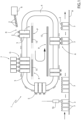
Figure 1 is a schematic side view of a cap applicator system according to the present invention, with parts removed for clarity; -
Figure 2 is a larger-scale, schematic side view, with parts removed for clarity, of a cart of the cap applicator system ofFigure 1 interacting with a track of the cap applicator system ofFigure 1 , during a first operative condition; and -
Figure 3 is a larger-scale, schematic side view, with parts removed for clarity, of the cart and track ofFigure 2 during a second operative condition. - With reference to
Figure 1 , number 1 indicates as a whole a non-limiting example of a cap applicator system for applyingcaps 2 topackages 3 containing a pourable product, preferably a pourable food product such as pasteurized or UHT milk, water, fruit juice, wine, peas, beans, etc. - In particular, the present description will refer, without however losing on generality, to a cap applicator system 1 which is part of a packaging line (known per se and not shown) comprising a packaging machine configured for producing a plurality of
packages 3 in a known manner. - As a non-limiting example, the packaging machine is configured for forming, sealing and
folding packages 3 starting from a tube of packaging material, in a manner known and not described in detail. - To this end, the packaging machine comprises:
- a filling device (not shown) for filling the tube with the pourable product;
- a forming and sealing device (not shown) for forming and sealing the tube, thereby obtaining a plurality of pillow packs, according to a manner known and not described in detail; and
- a folding device (not shown) for folding the pillow packs, thereby obtaining said
packages 3, according to a manner known and not described in detail. - Hence, the packaging machine is configured to form and seal a plurality of pillow packs containing the pourable product starting from the tube and then to fold the pillow packs for obtaining the aforementioned formed, sealed and folded
packages 3 containing the pourable product. - Preferably, the packaging material has a multilayer structure (not shown), and comprises a layer of fibrous material, e.g. paper, covered on both sides with respective layers of heat-seal plastic material, e.g. polyethylene.
- In the case of
aseptic packages 3 for long-storage products, such as UHT milk, the packaging material also comprises a layer of gas-and-light barrier material, e.g. aluminum foil or ethylene vinyl alcohol (EVOH) film, which is superimposed on a layer of heat-seal plastic material, and is in turn covered with another layer of heat-seal plastic material, the latter forming the inner face ofpackage 3 eventually contacting the pourable product. - Preferably, without however losing generality, system 1 is configured to apply
caps 2 made of plastic material. - Each
package 3 includes a so-called prelaminated hole or PLH which is of the type described above in the introductory portion of the description. - Cap applicator system 1 is configured to sequentially apply each
cap 2 onto a respective PLH, so as to cover and overlap the PLH. - In one embodiment, each
cap 2 may also provide for the first piercing of the oxygen-barrier layer of the PLH, according to a manner known and not described in detail. - According to a preferred embodiment, cap applicator system 1 is configured to receive
packages 3 from the folding device. - As schematically shown in
Figure 1 , cap applicator system 1 essentially comprises: - an
endless track 4; - a plurality of
carts 5 movably coupled withtrack 4; - a linear motor configured to move
carts 5 alongtrack 4 selectively and independently from one another. - In detail, linear motor incudes a plurality of individually-excitable (with electrical energy) solenoids or inductive coils distributed along
track 4, whereas eachcart 5 includes at least one permanent magnet. The electromagnetic interaction between the coils and the permanent magnets produces the motion ofcarts 5 alongtrack 4, in a manner known and not described in detail. - Cap applicator system 1 further comprises (
Figure 1 ) one or more of: - a cap feeder 6 arranged along
track 4, defining a receiving station R and configured to feedcaps 2 tocarts 5 transiting through receiving station R, respectively; - a
gluing device 7 arranged alongtrack 4 in a position operatively downstream of cap feeder 6, defining a gluing station G and configured to spread glue ontocaps 2 conveyed therethrough by therespective carts 5; and - an application station A arranged along
track 4 in a position operatively downstream of gluingdevice 7 and at whichcarts 5 cooperate withpackages 3 for applying therespective caps 2 thereon. - Accordingly, a sequence of
packages 3 is advanced, in use, at application station A. - More specifically, cap applicator system 1 may comprise a
conveyor 8, e.g. a belt conveyor, extending through application station A and configured to conveypackages 3 at and through application station A, so as to undergo the cap application as explained above. - In light of the above each
cart 5 is configured to cyclically receive onerespective cap 2 from cap feeder 6 at receiving station R, to retain and conveysuch cap 2 alongtrack 4 and through gluing station G whereby gluingdevice 7 spreads glue thereon, and to applysuch cap 2 onto onerespective package 3 at application station A. - To this end,
track 4 expediently extends through receiving station R, gluing station G and application station A. - After the cap application, each
cart 5 completes the length of theendless track 4 and goes back at receiving station R, for performing another cap application cycle. - For the sake of brevity, reference will be made in the following to a
single cart 5. The structural and functional features described in connection therewith are applicable to eachcart 5 of cap applicator system 1. - According to a first aspect of the present invention,
cart 5 comprises at least one electrically-powerable component 10 and areceiver 11 configured for receiving electrical energy and poweringcomponent 10. - According to a second aspect of the present invention, cap applicator system 1 comprises a powering station P arranged along
track 4 and configured for transmitting electrical energy. - According to a third aspect of the present invention, the linear motor is configured to selectively move
cart 5 through powering station P, wherebyreceiver 11 receives electrical energy from powering station P thereby poweringcomponent 10. - In particular, upon passage or transiting of
cart 5 through powering station P,receiver 11 interacts with powering station P (which for example may comprise a suitable transmitter for transmitting the electrical energy), thereby receiving electrical energy with which it powerscomponent 10. For example, the powering station P may generate an electromagnetic field which may induce a current in thereceiver 11. - It is specified that, according to the invention, powering station P is electrically separated from the solenoids or inductive coils of
track 4, and more generally electrically separated and distinct from the linear motor. - In light of the above, each
cart 5 can gather electrical energy for powering an electrically-powerable component 10 thereof in a relatively simple manner and without interfering with the electric powering of thecart 5 itself by means of the linear motor. - According to the non-limiting embodiment shown,
cart 5 includes a grippingunit 12 which is configured to cyclically grip at least onecap 2, in particular onesingle cap 2, at receiving station R, to retainsuch cap 2 during advancement ofcart 5 alongtrack 4, and to releasecap 2 at application station A (opportunely aftercap 2 has been spread with glue at gluing station G). - According to the invention, electrically-
powerable component 10 comprises saidgripping unit 12. - In particular, gripping
unit 12 comprises: - a
gripper 13 for cyclically retaining arespective cap 2 between receiving station R, at which gripper 13 receives and gripssuch cap 2, and application station A, at which gripper releases and appliescap 2 onto arespective package 3; and - an actuator 14 (of the type known and only schematically shown for the purposes of the present invention) for driving a movement of
gripper 13 relatively tocart 5 during the advancement ofsuch cart 5 alongtrack 4. -
Actuator 14 may include an electric motor.Actuator 14 may include suitable gears and/or transmission means for mechanical coupling withgripper 13. - According to the invention,
receiver 11 is electrically coupled withactuator 14, and is configured for poweringactuator 14 with electrical energy received from powering station P. - More specifically,
actuator 14 may be configured for driving: - a movement of
gripper 13 relatively to cart 5 along a first direction Y parallel to track 4; and/or - a movement of
gripper 13 relatively to cart 5 along a second direction X transversal to track 4; and/or - a movement of
gripper 13 relatively to cart 5 along a third direction Z orthogonal to track 4 and directed outwardly with respect to track 4 itself; and/or - a composite motion of the above movements; and/or
- a rotation of the cap about its own axis.
- More precisely, first direction Y is defined as being parallel to track 4 along its entire length; second direction X is defined as being orthogonal to track 4 and to first direction Y; and third direction Z is defined as being orthogonal to track 4 and to first direction Y and second direction X and directed outwardly with respect to track 4 itself.
- According to the invention,
actuator 14 is powerable by means of powering station P, i.e. by means ofcart 5 passing through powering station P and by means ofreceiver 11 receiving thereby electrical energy from powering station P. - In other words, cap applicator system 1 according to the present invention allows to obtain a "power on board" configuration.
- Thanks to the above configuration, a movement of
cap 2 with respect to its initial gripping position and with respect to track 4 can be easily obtained exploiting the "power on board" provided by powering station P, without the need for anadditional track 4 and a pair ofcarts 5 coupled with a lever mechanism for eachcap 2 to be gripped and conveyed, as it is the case for the systems according to the state of the art. - Accordingly,
track 4 is advantageously defined by a single closed-loop rail, and eachcart 5 comprises only one single cart movably coupled to the closed-loop rail. - In this way, an adjustment of the position of each
cap 2 can be easily obtained, without involving asecond track 4 or pairs of kinematically coupledcarts 5, thereby reducing the number of components of system 1, increasing its reliability and easing the maintenance thereof. - Furthermore, the necessary rotating motion for correctly spreading glue onto each
cap 2 at gluing station G may be easily provided thanks to the "power on board" configuration according to the invention. - As schematically shown in
Figures 1 ,2 and 3 , powering station P comprises an energizingtrack 15 which extends along at least part oftrack 4. - According to the invention,
cart 5 is configured to advance therespective receiver 11 along energizingtrack 15 for interacting therewith and being thus energized with electrical energy. - In practice, powering station P is defined by energizing
track 15. - Expediently, energizing
track 15 extends at least at receiving station R and at application station A. - Conveniently, energizing
track 15 extends also at gluing station G. - In this way,
cart 5 may receive power from energizing track 15 (i.e. from powering station P) for energizingcomponent 10, and particularlyactuator 14, at said stations R, G, A, and thereby driving a movement ofgripper 13, and therefore of therespective cap 2, at said stations. - In other words, powering station P preferably has a discontinuous configuration, comprising a discontinuous energizing
track 15 which extends only at stations R, G, A. - It may be said that several powering stations P and thus energizing
tracks 15 are present in system 1, or that energizingtrack 15 has several portions alongtrack 4. - In this way,
cart 5 guarantees the desired degrees of freedom to gripper 13, and therefore to cap 2, at receiving station R, gluing station G and application station A, by means ofactuator 14 powered with energizingtrack 15, whereas when such degrees of freedom are not needed (e.g. in between these stations R, G, A) energizingtrack 15 is absent. - Number of components and the overall costs associated with system 1 can therefore be maintained low.
- Moreover, system 1 may acquire a highly increased flexibility in terms of positioning of cap feeder 6, gluing
device 7 and application station A, simply by displacing the various portions of energizingtrack 15 as desired. - Furthermore, wear is highly reduced, since mechanical contacts between cams and cam followers are reduced in number.
- Also flexibility of system 1 in terms of format change is highly increased: it is in fact sufficient to appropriately control the extent of the aforesaid movement (e.g. by means of a suitable control unit and within the stroke limits of actuator 14) to rapidly and easily adjust the position of
cap 2 to different types ofpackages 3 and/or the position ofgripper 13 to different types ofcaps 2. - Some examples of the aforementioned movements drivable by means of system 1 are presented hereinafter.
- For example,
actuator 14 may be powered at receiving station R to drive a translational movement ofgripper 13 towards cap feeder 6, forbetter picking cap 2 and/or adapting to different cap formats. - For example,
actuator 14 may be powered at gluing station G to drive a rotational movement ofgripper 13 being a composition of translations, thereby imparting to the grippedcap 2 the necessary rotation motion for being spread with glue. - For example,
actuator 14 may be powered upstream of application station A to drive a translational and/or rotational movement ofgripper 13, thereby adjusting a positioning ofcap 2 adapting to the real position of the PLH on therespective package 3. - To this end, cap applicator system 1 may further comprise a
detector 16 arranged facingconveyor 8 upstream of application station A for detecting the positioning of each PLH onpackages 3, with respect to a nominal positioning. - Each detection is then logically provided to the
respective cart 5, which will therefore adjust the position ofcap 2 accordingly, thanks to the configuration according to the present invention. - In this regard, it is specified that powering station P is further configured to transmit to each
receiver 11 logic information (i.e. control information or controls) through the electrical energy. - Accordingly, each
cart 5 is conveniently equipped with a control unit (of the known type) configured for receiving the logic information or control information from powering station P, and to controlcomponent 10 accordingly. - Finally, for
example actuator 14 may be powered at application station A to drive a translational movement ofgripper 13, for better application ofcap 2 ontopackage 3 and thereby imparting a pressing action ofcap 2 ontopackage 3 which may improve the application thereon. - In light of the above, cap applicator system 1 comprises a plurality of powering stations P, each one located at a respective station R, G, A.
- Conveniently, as schematized in
Figures 2 and 3 , powering station P is configured for transmitting electrical energy toreceiver 11 of eachcart 5 by means of wireless power transfer. - In practice, as visible in
Figures 2 and 3 , there is a space between energizingtrack 15 and eachreceiver 11, so that there is no physical contact between them. - This allows for a substantial reduction of wear due to contactless interaction between these two parts.
- Preferably, energizing
track 15 includes a first electric circuit andreceiver 11 includes a second electric circuit. The transmission of electrical energy from the first electric circuit to the second electric circuit occurs by means of electrical induction, thereby defining the wireless transfer (i.e. the wireless electrical connection). - Alternatively, energizing
track 15 andreceiver 11 may cooperate in sliding contact with one another, for example by means of electrically conductive brushes. In this case, the transfer of electrical energy may be more effective and with less dispersions, albeit entailing an increased wear with respect to the aforesaid wireless transfer. - In one embodiment,
gripper 13 may be controllable in an open configuration, for receiving or releasing therespective cap 2, and in a closed configuration, for gripping and retaining therespective cap 2. - Advantageously,
actuator 14 may be configured for controllinggripper 13 between the open configuration and the closed configuration. - In this way, powering station P may also provide the control and driving necessary for actively gripping and releasing
cap 2, thereby avoiding the need for further dedicated cam systems at receiving station R and application station A. - According to an alternative embodiment not shown, gripping
unit 12 may comprise: - a vacuum pump (of the known type and not shown);
- a gripper for cyclically retaining a
respective cap 2 between receiving station R and application station A, the gripper having a vacuum port fluidly connectable to the vacuum pump for retainingcap 2 by suction. - Accordingly,
receiver 11 may be configured for powering the vacuum pump with electrical energy received from powering station P. - It is thus clear that the "power on board" configuration of system 1 according to the invention allows for an easy, simple and rather flexible powering and control of various electrically-powerable devices and components.
- In this regard, according to an alternative embodiment not shown, each
cart 5 includes at least onesensor 17 configured to detect a physical quantity indicative of thecap 2 received bycart 5 or of thecart 5 itself.Sensor 17 may be embedded in a frame or body ofcart 5. - As an example,
sensor 17 may be configured to detect one or more of the following: - a position of
cap 2 relative to cart 5; - a presence of
cap 2 oncart 5; - a nominal gripping of
cap 2 bycart 5, i.e. bygripper 13; - a weight of
cap 2; - an orientation of
cap 2; - an acceleration of
cart 5; - a speed of
cart 5. - According to the invention, the aforesaid electrically-
powerable component 10 comprisessensor 17. - Accordingly,
receiver 11 is configured for poweringsensor 17 with electrical energy received from powering station P, i.e. from energizingtrack 15. - For example, during the passage of
cart 5 through receiving station R, and the related powering station P,sensor 17 is powered (via receiver 11) for detecting a weight of thecap 2 received or an orientation ofsuch cap 2. - In this way, a simple and effective electric powering of a
sensor 17 oncart 5 may be obtained, without interfering with the linear motor and without the need for complicated electrical energy transmission system, which would be incompatible with the linear motor (such as cables or other complicated and/or cumbersome means). - Conveniently, cap applicator system 1 includes a control unit which is configured to (individually) control each
cart 5. The control unit of the cap applicator system 1 may be configured to logically communicate (i.e. to electronically exchange information) with the aforementioned control units of eachcart 5. - Hence, a wireless communication between such control units can be easily established, by means of which the control unit of cap applicator system 1 can remotely control the actuation of component 10 (i.e. of gripping
unit 12 and/or sensor 17). - Advantageously, each
cart 5 includes an electrical energy storage member (not shown), such as a battery, electrically connected withreceiver 11 and with component 10 (i.e. withactuator 14 and/or sensor 17) and configured to store electrical energy supplied fromreceiver 11, in particular for a predetermined amount of time, and to supply the stored electrical energy tocomponent 10. - Only one powering station P may be present, for example at receiving station R, since the storage member may provide electrical energy to
component 10 throughout all the application cycle. - In other words,
component 10 may be cyclically powered only once by interaction ofreceiver 11 with the single powering station P. As a result, an even more reduced wear and an even more simplified architecture may be obtained. - From the foregoing description, it is clear how cap applicator system 1 according to the invention allows to implement a method for applying
caps 2 ontopackages 3 containing a pourable product, the method comprising the steps of: - advancing a plurality of
packages 3 through an application station A; - advancing a plurality of
carts 5 along anendless track 4 and through a receiving station R and the application station A by means of a linear motor, eachcart 5 including at least one electrically-powerable component 10 and areceiver 11 for receiving electrical energy and powering thecomponent 10; - conveying
caps 2 from the receiving station R to the application station A by means of thecarts 5, respectively; - selectively moving each
cart 5 through a powering station P configured for transmitting electrical energy; - transmitting electrical energy to each
receiver 11 by means of the powering station P and upon transiting of therespective cart 5 through the powering station P; - powering the
component 10 with the electrical energy received from the powering station P. - The advantages of cap applicator system 1 according to the present invention will be clear from the foregoing description.
- The powering station P may comprise a portion of the endless track where wireless power transfer is possible. That is, the
cart 5 transits through the powering station at which it is possible for it to receive electrical power. - In particular, a relatively simple, reliable, flexible, safe and wearproof cap applicator system 1 for applying
caps 2 ontopackages 3 containing pourable product is obtained. - In fact, wear is substantially reduced, thanks to the linear motor and thanks to the fact that
receivers 11 and energizingtracks 15 preferably interact with one another with little or no contact. - Moreover, the number of components of system 1 is highly reduced with respect to the known systems: only a
single track 4 andsingle carts 5 instead of pairs of kinematically linked carts are sufficient for obtaining the desired movements ofgripper 13 and caps 2. - Accordingly, the need for maintenance and overall cost of system 1 are significantly reduced.
- Furthermore, a
sensor 17 may be implemented on eachcart 5 and very easily powered by the "power on board" configuration of system 1 according to the invention. - In addition, thanks to such "power on board" configuration, flexibility of system 1 in terms of package and/or cap format change is highly increased.
- Clearly, changes may be made to cap applicator system 1 as described herein without, however, departing from the scope of protection as defined in the accompanying claims.
- In particular, each
cart 5 may include only one of the grippingunit 12 and thesensor 17 or both the grippingunit 12 and thesensor 17. - That is, the electrically-
powerable component 10 may comprise, and in particular may be defined, by one or both of the above.
Claims (16)
- - Cap applicator system (1) for applying caps (2) onto packages (3) containing a pourable product, the cap applicator system (1) comprising:- an endless track (4);- a plurality of cart members (5) movably coupled with the endless track (4), each cart member (5) having at least one electrically-powerable component (10) and a receiver (11) configured for receiving electrical energy and powering the component (10);- a linear motor configured to move the cart members (5) along the endless track (4) selectively and independently from one another, each cart member (5) being configured to cyclically receive one respective cap (2) at a receiving station (R), to retain and convey such cap (2) along the endless track (2), and to apply such cap (2) onto one respective package (3) at an application station (A); and- at least one powering station (P) arranged along at least a portion of the endless track (4) and configured for transmitting electrical energy;wherein the linear motor is configured to selectively move each cart member (5) through the powering station (P), whereby the receiver (11) receives electrical energy from the powering station (P) thereby powering the component (10).
- - Cap applicator system as claimed in claim 1, wherein the powering station (P) is configured for transmitting electrical energy to the receiver (11) of each cart member (5) by means of wireless power transfer.
- - Cap applicator system as claimed in claim 1 or 2, wherein the powering station (P) comprises an energizing track (15) extending along at least part of the endless track (4),
and wherein each cart member (5) is configured to advance the respective receiver (11) along the energizing track (15) for interacting therewith and being thus energized with electrical energy. - - Cap applicator system as claimed in any of the previous claims, wherein the powering station (P) extends at least at the receiving station (R) and/or at the application station (A).
- - Cap applicator system as claimed in any of the previous claims, wherein the powering station (P) further extends at a gluing station (G), the gluing station (G) being operatively interposed between the receiving station (R) and the application station (A);
wherein each cart member (5) is configured to convey the respective cap (2) through the gluing station (G), at which such cap (2) is spread with glue. - - Cap applicator system as claimed in any one of the foregoing claims, wherein each cart member (5) includes a gripping unit (12) which is configured to cyclically grip at least one cap (2) at the receiving station (R), to retain such cap (2) during advancement of the cart member (5) along the endless track (15), and to release the cap (2) at the application station (A);
and wherein the electrically-powerable component (10) comprises said gripping unit (12). - - Cap applicator system as claimed in claim 6, wherein the gripping unit (12) comprises:- a gripper (13) for cyclically retaining a respective cap (2) between the receiving station (R) and the application station (A);- an actuator (14) for driving a movement of the gripper (13) relatively to the respective cart member (5) during the advancement of the cart member (5) along the endless track (4) ;wherein the receiver (11) is configured for powering the actuator (14) with electrical energy received from the powering station (P).
- - Cap applicator system as claimed in claim 7, wherein the actuator (14) is configured for driving:- a movement of the gripper (13) relatively to the respective cart member (5) along a first direction (Y) parallel to the endless track (4); and/or- a movement of the gripper (13) relatively to the respective cart member (5) along a second direction (X, Z) transversal or orthogonal to the endless track (14); and/or- a composite motion of the above movements; and/or- a rotation of the cap (2) about its own axis.
- - Cap applicator system as claimed in any of claims 6 to 8, wherein the gripper (13) is controllable in an open configuration, for receiving or releasing the respective cap (2), and in a closed configuration, for gripping and retaining the respective cap (2);
and wherein the gripping unit (12) comprises an actuator (14) configured for controlling the gripper (13) between the open configuration and the closed configuration. - - Cap applicator system as claimed in claim 6, wherein the gripping unit (12) comprises:- a vacuum pump;- a gripper for cyclically retaining a respective cap (2) between the receiving station and the application station, the gripper having a vacuum port fluidly connectable to the vacuum pump for retaining the cap (2) by suction;and wherein the receiver (11) is configured for powering the vacuum pump with electrical energy received from the powering station (P).
- - Cap applicator system as claimed in any one of the foregoing claims, wherein each cart member (5) includes at least one sensor (17) configured to detect a physical quantity indicative of the cap (2) received by the cart member (5) or of such cart member (5);
and wherein the electrically-powerable component (10) comprises the at least one sensor (17). - - Cap applicator system as claimed in claim 11, wherein the receiver (11) is configured for powering the sensor (17) with electrical energy received from the powering station (P);
and wherein the sensor (17) is configured to detect one or more of the following:- a position of the cap (2) relative to the cart member (5) ;- a presence of the cap (2) on the cart member (5);- a nominal gripping of the cap (2) by the cart member (5) ;- a weight of the cap (2);- an orientation of the cap (2);- an acceleration of the cart member (5);- a speed of the cart member (5). - - Cap applicator system as claimed in any one of the foregoing claims, wherein the endless track (4) is defined by a single closed-loop rail, and wherein each cart member (5) comprises one single cart movably coupled to the closed-loop rail.
- - Cap applicator system as claimed in any one of the foregoing claims, wherein each cart member (5) includes an electrical energy storage member electrically connected with the receiver (11) and with the component (10) and configured to store electrical energy supplied from the receiver (11) and to supply the stored electrical energy to the component (10) .
- - Packaging line configured for producing packages (3), comprising a packaging machine configured for forming, sealing and folding packages (3) containing a pourable product, and a cap applicator system (1) as claimed in any one of the foregoing claims and configured to receive the folded packages for applying caps (2) thereon.
- - Method for applying caps (2) onto packages (3) containing a pourable product, the method comprising the steps of:- advancing a plurality of packages (3) through an application station (A);- advancing a plurality of cart members (5) along an endless track (4) and through a receiving station (R) and the application station (A) by means of a linear motor, each cart member (5) including at least one electrically-powerable component (10) and a receiver (11) for receiving electrical energy and powering the component (10);- conveying caps (2) from the receiving station (R) to the application station (A) by means of the cart members (5), respectively;- selectively moving each cart member (5) through a powering station (P) configured for transmitting electrical energy;- transmitting electrical energy to each receiver (11) by means of the powering station (P) and upon transiting of the respective cart member (5) through the powering station (P) ;- powering the component (10) with the electrical energy received from the powering station (P).
Applications Claiming Priority (1)
| Application Number | Priority Date | Filing Date | Title |
|---|---|---|---|
| IT202300015081 | 2023-07-18 |
Publications (2)
| Publication Number | Publication Date |
|---|---|
| EP4495018A1 true EP4495018A1 (en) | 2025-01-22 |
| EP4495018B1 EP4495018B1 (en) | 2026-02-04 |
Family
ID=88291352
Family Applications (1)
| Application Number | Title | Priority Date | Filing Date |
|---|---|---|---|
| EP24187970.9A Active EP4495018B1 (en) | 2023-07-18 | 2024-07-11 | Cap applicator system for a packaging machine and method for applying caps |
Country Status (4)
| Country | Link |
|---|---|
| EP (1) | EP4495018B1 (en) |
| JP (1) | JP2026524684A (en) |
| CN (1) | CN121548540A (en) |
| WO (1) | WO2025016855A1 (en) |
Citations (6)
| Publication number | Priority date | Publication date | Assignee | Title |
|---|---|---|---|---|
| US20010032438A1 (en) * | 2000-03-31 | 2001-10-25 | Iman Pack S.P.A. | Machine for fixing lids to packages for moist wipes, tissues or the like |
| WO2014009275A1 (en) | 2012-07-13 | 2014-01-16 | Pyrolyx Ag | Method and device for the production of furnace black using solid rubber particles |
| EP2746175A1 (en) * | 2012-12-21 | 2014-06-25 | Tetra Laval Holdings & Finance S.A. | Unit for the application of opening devices on sealed packages of food products |
| EP3882164A1 (en) * | 2020-03-20 | 2021-09-22 | Tetra Laval Holdings & Finance S.A. | Method for controlling a plurality of carts movable along an endless track |
| EP4071569A1 (en) * | 2021-04-07 | 2022-10-12 | Rockwell Automation Technologies, Inc. | System and method for determining real-time orientation on carts in an independent cart system |
| CN218890845U (en) * | 2022-11-30 | 2023-04-21 | 昆山炬多智能设备有限公司 | Heavy-duty cross belt sorting machine |
-
2024
- 2024-07-11 EP EP24187970.9A patent/EP4495018B1/en active Active
- 2024-07-11 CN CN202480047494.0A patent/CN121548540A/en active Pending
- 2024-07-11 WO PCT/EP2024/069638 patent/WO2025016855A1/en not_active Ceased
- 2024-07-11 JP JP2026502227A patent/JP2026524684A/en active Pending
Patent Citations (6)
| Publication number | Priority date | Publication date | Assignee | Title |
|---|---|---|---|---|
| US20010032438A1 (en) * | 2000-03-31 | 2001-10-25 | Iman Pack S.P.A. | Machine for fixing lids to packages for moist wipes, tissues or the like |
| WO2014009275A1 (en) | 2012-07-13 | 2014-01-16 | Pyrolyx Ag | Method and device for the production of furnace black using solid rubber particles |
| EP2746175A1 (en) * | 2012-12-21 | 2014-06-25 | Tetra Laval Holdings & Finance S.A. | Unit for the application of opening devices on sealed packages of food products |
| EP3882164A1 (en) * | 2020-03-20 | 2021-09-22 | Tetra Laval Holdings & Finance S.A. | Method for controlling a plurality of carts movable along an endless track |
| EP4071569A1 (en) * | 2021-04-07 | 2022-10-12 | Rockwell Automation Technologies, Inc. | System and method for determining real-time orientation on carts in an independent cart system |
| CN218890845U (en) * | 2022-11-30 | 2023-04-21 | 昆山炬多智能设备有限公司 | Heavy-duty cross belt sorting machine |
Also Published As
| Publication number | Publication date |
|---|---|
| JP2026524684A (en) | 2026-07-23 |
| WO2025016855A1 (en) | 2025-01-23 |
| CN121548540A (en) | 2026-02-17 |
| EP4495018B1 (en) | 2026-02-04 |
Similar Documents
| Publication | Publication Date | Title |
|---|---|---|
| US9403611B2 (en) | Unit for sequencing and guiding items | |
| US10994873B2 (en) | Packaging assembly for forming and sealing a plurality of packs containing a pourable food product | |
| EP2935024B1 (en) | Unit for the application of opening devices on sealed packages of food products | |
| CN105916770B (en) | Unit for applying cover of opening device | |
| WO2008122623A2 (en) | Folding unit for producing sealed packages of pourable food products | |
| EP4549328A2 (en) | A device for performing operations on a packaging material for the production of packages containing a pourable product and related method | |
| EP1462370B1 (en) | Unit for applying opening devices to packages of pourable food products | |
| EP4495018B1 (en) | Cap applicator system for a packaging machine and method for applying caps | |
| EP4414277A1 (en) | Tag applicator device for a packaging line configured for forming, sealing and folding a plurality of packages containing a pourable product | |
| JP7059293B2 (en) | Filling machine for filling flexible pouch-type packages | |
| EP4480870A1 (en) | Conveyor device for a packaging machine and packaging machine | |
| WO2023198615A1 (en) | Infeed conveyor for a folding apparatus, folding apparatus having an infeed conveyor and packaging machine having a folding apparatus | |
| EP4506270A1 (en) | Forming unit for forming sealed packs containing a pourable product and method for forming sealed packs containing a pourable product | |
| EP4506268A1 (en) | Feeding unit for feeding semi-finished packs to a folding unit | |
| HK1077791B (en) | A forming unit for producing sealed packages from a tube of sheet packaging material | |
| HK1141262B (en) | Folding unit for producing sealed packages of pourable food products | |
| HK1077791A1 (en) | A forming unit for producing sealed packages from a tube of sheet packaging material |
Legal Events
| Date | Code | Title | Description |
|---|---|---|---|
| PUAI | Public reference made under article 153(3) epc to a published international application that has entered the european phase |
Free format text: ORIGINAL CODE: 0009012 |
|
| STAA | Information on the status of an ep patent application or granted ep patent |
Free format text: STATUS: THE APPLICATION HAS BEEN PUBLISHED |
|
| AK | Designated contracting states |
Kind code of ref document: A1 Designated state(s): AL AT BE BG CH CY CZ DE DK EE ES FI FR GB GR HR HU IE IS IT LI LT LU LV MC ME MK MT NL NO PL PT RO RS SE SI SK SM TR |
|
| STAA | Information on the status of an ep patent application or granted ep patent |
Free format text: STATUS: REQUEST FOR EXAMINATION WAS MADE |
|
| 17P | Request for examination filed |
Effective date: 20250722 |
|
| GRAP | Despatch of communication of intention to grant a patent |
Free format text: ORIGINAL CODE: EPIDOSNIGR1 |
|
| STAA | Information on the status of an ep patent application or granted ep patent |
Free format text: STATUS: GRANT OF PATENT IS INTENDED |
|
| RIC1 | Information provided on ipc code assigned before grant |
Ipc: B65B 7/28 20060101AFI20251024BHEP Ipc: B65B 61/18 20060101ALI20251024BHEP Ipc: B65B 65/00 20060101ALI20251024BHEP Ipc: B65B 65/02 20060101ALI20251024BHEP Ipc: B65G 47/28 20060101ALI20251024BHEP Ipc: B65G 54/02 20060101ALI20251024BHEP Ipc: B65B 51/02 20060101ALI20251024BHEP Ipc: B65B 57/04 20060101ALI20251024BHEP |
|
| INTG | Intention to grant announced |
Effective date: 20251112 |
|
| GRAS | Grant fee paid |
Free format text: ORIGINAL CODE: EPIDOSNIGR3 |
|
| GRAA | (expected) grant |
Free format text: ORIGINAL CODE: 0009210 |
|
| STAA | Information on the status of an ep patent application or granted ep patent |
Free format text: STATUS: THE PATENT HAS BEEN GRANTED |
|
| AK | Designated contracting states |
Kind code of ref document: B1 Designated state(s): AL AT BE BG CH CY CZ DE DK EE ES FI FR GB GR HR HU IE IS IT LI LT LU LV MC ME MK MT NL NO PL PT RO RS SE SI SK SM TR |
|
| REG | Reference to a national code |
Ref country code: CH Ref legal event code: F10 Free format text: ST27 STATUS EVENT CODE: U-0-0-F10-F00 (AS PROVIDED BY THE NATIONAL OFFICE) Effective date: 20260204 Ref country code: GB Ref legal event code: FG4D |
|
| REG | Reference to a national code |
Ref country code: IE Ref legal event code: FG4D |
|
| REG | Reference to a national code |
Ref country code: DE Ref legal event code: R096 Ref document number: 602024002385 Country of ref document: DE |
|
| REG | Reference to a national code |
Ref country code: NL Ref legal event code: MP Effective date: 20260204 |
|
| PG25 | Lapsed in a contracting state [announced via postgrant information from national office to epo] |
Ref country code: RS Free format text: LAPSE BECAUSE OF FAILURE TO SUBMIT A TRANSLATION OF THE DESCRIPTION OR TO PAY THE FEE WITHIN THE PRESCRIBED TIME-LIMIT Effective date: 20260504 |
|
| PG25 | Lapsed in a contracting state [announced via postgrant information from national office to epo] |
Ref country code: ES Free format text: LAPSE BECAUSE OF FAILURE TO SUBMIT A TRANSLATION OF THE DESCRIPTION OR TO PAY THE FEE WITHIN THE PRESCRIBED TIME-LIMIT Effective date: 20260204 |
|
| PG25 | Lapsed in a contracting state [announced via postgrant information from national office to epo] |
Ref country code: PL Free format text: LAPSE BECAUSE OF FAILURE TO SUBMIT A TRANSLATION OF THE DESCRIPTION OR TO PAY THE FEE WITHIN THE PRESCRIBED TIME-LIMIT Effective date: 20260204 |
|
| PG25 | Lapsed in a contracting state [announced via postgrant information from national office to epo] |
Ref country code: GR Free format text: LAPSE BECAUSE OF FAILURE TO SUBMIT A TRANSLATION OF THE DESCRIPTION OR TO PAY THE FEE WITHIN THE PRESCRIBED TIME-LIMIT Effective date: 20260505 |
|
| REG | Reference to a national code |
Ref country code: LT Ref legal event code: MG9D |
|
| PG25 | Lapsed in a contracting state [announced via postgrant information from national office to epo] |
Ref country code: LT Free format text: LAPSE BECAUSE OF FAILURE TO SUBMIT A TRANSLATION OF THE DESCRIPTION OR TO PAY THE FEE WITHIN THE PRESCRIBED TIME-LIMIT Effective date: 20260204 |
|
| PG25 | Lapsed in a contracting state [announced via postgrant information from national office to epo] |
Ref country code: NO Free format text: LAPSE BECAUSE OF FAILURE TO SUBMIT A TRANSLATION OF THE DESCRIPTION OR TO PAY THE FEE WITHIN THE PRESCRIBED TIME-LIMIT Effective date: 20260504 |
|
| PG25 | Lapsed in a contracting state [announced via postgrant information from national office to epo] |
Ref country code: FI Free format text: LAPSE BECAUSE OF FAILURE TO SUBMIT A TRANSLATION OF THE DESCRIPTION OR TO PAY THE FEE WITHIN THE PRESCRIBED TIME-LIMIT Effective date: 20260204 Ref country code: AT Free format text: LAPSE BECAUSE OF FAILURE TO SUBMIT A TRANSLATION OF THE DESCRIPTION OR TO PAY THE FEE WITHIN THE PRESCRIBED TIME-LIMIT Effective date: 20260204 Ref country code: SE Free format text: LAPSE BECAUSE OF FAILURE TO SUBMIT A TRANSLATION OF THE DESCRIPTION OR TO PAY THE FEE WITHIN THE PRESCRIBED TIME-LIMIT Effective date: 20260204 |
|
| REG | Reference to a national code |
Ref country code: AT Ref legal event code: MK05 Ref document number: 1883905 Country of ref document: AT Kind code of ref document: T Effective date: 20260204 |
|
| PG25 | Lapsed in a contracting state [announced via postgrant information from national office to epo] |
Ref country code: HR Free format text: LAPSE BECAUSE OF FAILURE TO SUBMIT A TRANSLATION OF THE DESCRIPTION OR TO PAY THE FEE WITHIN THE PRESCRIBED TIME-LIMIT Effective date: 20260204 |
|
| PG25 | Lapsed in a contracting state [announced via postgrant information from national office to epo] |
Ref country code: PT Free format text: LAPSE BECAUSE OF FAILURE TO SUBMIT A TRANSLATION OF THE DESCRIPTION OR TO PAY THE FEE WITHIN THE PRESCRIBED TIME-LIMIT Effective date: 20260605 Ref country code: IS Free format text: LAPSE BECAUSE OF FAILURE TO SUBMIT A TRANSLATION OF THE DESCRIPTION OR TO PAY THE FEE WITHIN THE PRESCRIBED TIME-LIMIT Effective date: 20260604 |
|
| PG25 | Lapsed in a contracting state [announced via postgrant information from national office to epo] |
Ref country code: NL Free format text: LAPSE BECAUSE OF FAILURE TO SUBMIT A TRANSLATION OF THE DESCRIPTION OR TO PAY THE FEE WITHIN THE PRESCRIBED TIME-LIMIT Effective date: 20260204 |
|
| PG25 | Lapsed in a contracting state [announced via postgrant information from national office to epo] |
Ref country code: LV Free format text: LAPSE BECAUSE OF FAILURE TO SUBMIT A TRANSLATION OF THE DESCRIPTION OR TO PAY THE FEE WITHIN THE PRESCRIBED TIME-LIMIT Effective date: 20260204 |
|
| PG25 | Lapsed in a contracting state [announced via postgrant information from national office to epo] |
Ref country code: BG Free format text: LAPSE BECAUSE OF FAILURE TO SUBMIT A TRANSLATION OF THE DESCRIPTION OR TO PAY THE FEE WITHIN THE PRESCRIBED TIME-LIMIT Effective date: 20260204 |