EP4495015A1 - Methods and apparatus to repair composite airfoil structures - Google Patents
Methods and apparatus to repair composite airfoil structures Download PDFInfo
- Publication number
- EP4495015A1 EP4495015A1 EP24187180.5A EP24187180A EP4495015A1 EP 4495015 A1 EP4495015 A1 EP 4495015A1 EP 24187180 A EP24187180 A EP 24187180A EP 4495015 A1 EP4495015 A1 EP 4495015A1
- Authority
- EP
- European Patent Office
- Prior art keywords
- sheet
- leading edge
- doubler plate
- skin
- wing
- Prior art date
- Legal status (The legal status is an assumption and is not a legal conclusion. Google has not performed a legal analysis and makes no representation as to the accuracy of the status listed.)
- Pending
Links
Images





Classifications
-
- B—PERFORMING OPERATIONS; TRANSPORTING
- B64—AIRCRAFT; AVIATION; COSMONAUTICS
- B64F—GROUND OR AIRCRAFT-CARRIER-DECK INSTALLATIONS SPECIALLY ADAPTED FOR USE IN CONNECTION WITH AIRCRAFT; DESIGNING, MANUFACTURING, ASSEMBLING, CLEANING, MAINTAINING OR REPAIRING AIRCRAFT, NOT OTHERWISE PROVIDED FOR; HANDLING, TRANSPORTING, TESTING OR INSPECTING AIRCRAFT COMPONENTS, NOT OTHERWISE PROVIDED FOR
- B64F5/00—Designing, manufacturing, assembling, cleaning, maintaining or repairing aircraft, not otherwise provided for; Handling, transporting, testing or inspecting aircraft components, not otherwise provided for
- B64F5/40—Maintaining or repairing aircraft
-
- B—PERFORMING OPERATIONS; TRANSPORTING
- B29—WORKING OF PLASTICS; WORKING OF SUBSTANCES IN A PLASTIC STATE IN GENERAL
- B29C—SHAPING OR JOINING OF PLASTICS; SHAPING OF MATERIAL IN A PLASTIC STATE, NOT OTHERWISE PROVIDED FOR; AFTER-TREATMENT OF THE SHAPED PRODUCTS, e.g. REPAIRING
- B29C73/00—Repairing of articles made from plastics or substances in a plastic state, e.g. of articles shaped or produced by using techniques covered by this subclass or subclass B29D
- B29C73/02—Repairing of articles made from plastics or substances in a plastic state, e.g. of articles shaped or produced by using techniques covered by this subclass or subclass B29D using liquid or paste-like material
-
- B—PERFORMING OPERATIONS; TRANSPORTING
- B29—WORKING OF PLASTICS; WORKING OF SUBSTANCES IN A PLASTIC STATE IN GENERAL
- B29C—SHAPING OR JOINING OF PLASTICS; SHAPING OF MATERIAL IN A PLASTIC STATE, NOT OTHERWISE PROVIDED FOR; AFTER-TREATMENT OF THE SHAPED PRODUCTS, e.g. REPAIRING
- B29C73/00—Repairing of articles made from plastics or substances in a plastic state, e.g. of articles shaped or produced by using techniques covered by this subclass or subclass B29D
- B29C73/04—Repairing of articles made from plastics or substances in a plastic state, e.g. of articles shaped or produced by using techniques covered by this subclass or subclass B29D using preformed elements
- B29C73/10—Repairing of articles made from plastics or substances in a plastic state, e.g. of articles shaped or produced by using techniques covered by this subclass or subclass B29D using preformed elements using patches sealing on the surface of the article
-
- B—PERFORMING OPERATIONS; TRANSPORTING
- B64—AIRCRAFT; AVIATION; COSMONAUTICS
- B64C—AEROPLANES; HELICOPTERS
- B64C3/00—Wings
- B64C3/26—Construction, shape, or attachment of separate skins, e.g. panels
-
- B—PERFORMING OPERATIONS; TRANSPORTING
- B29—WORKING OF PLASTICS; WORKING OF SUBSTANCES IN A PLASTIC STATE IN GENERAL
- B29L—INDEXING SCHEME ASSOCIATED WITH SUBCLASS B29C, RELATING TO PARTICULAR ARTICLES
- B29L2031/00—Other particular articles
- B29L2031/30—Vehicles, e.g. ships or aircraft, or body parts thereof
- B29L2031/3076—Aircrafts
- B29L2031/3085—Wings
Definitions
- This disclosure relates generally to aircraft and, more particularly, to methods and apparatus to repair composite airfoil structures.
- a monocoque and/or semi-monocoque structures to carry primary stresses and/or maintain rigidity of a wing leading edge, winglet and/or wingtip of the aircraft.
- the monocoque and/or semi-monocoque structures can be susceptible to impact damage and require repair for aerodynamic requirements of an aircraft.
- the disclosure relates to an apparatus to repair a semi-monocoque wing.
- the apparatus comprises a doubler plate configured to be coupled to a skin of the semi-monocoque wing via a first adhesive, the doubler plate having a contour substantially complementary to a contour of a leading edge of the semi-monocoque wing, and a layer of tape positioned at least partially along at least a portion of an interface between an edge of the doubler plate and the leading edge of the skin.
- the doubler plate may include a first doubler plate attached to a second doubler plate via a second adhesive.
- the tape may overlap at least one of the edge of the doubler plate or the leading edge of the skin by, for instance, a range of about 3.81 cm (1.5 inches) and about 7.62 cm (3 inches).
- the first adhesive may include at least one of adhesive, paste or sealant.
- the doubler plate may have a thickness between approximately 1.016 mm (0.040 inches) and approximately 2.032 mm (0.080 inches).
- the doubler plate may include aluminum.
- the doubler plate may include galvanized steel.
- the tape may be speed tape.
- the wing may be a winglet and the leading edge may be located on a lower blade of the winglet.
- the wing may be a vertical stabilizer and the leading edge may be on the vertical stabilizer.
- the disclosure relates to a method to repair a semi-monocoque wing.
- the method includes: obtaining a sheet of material having a contour substantially complementary to a contour of a leading edge of the semi-monocoque wing; applying adhesive to at least one of a rear side of the sheet of material or a skin of the semi-monocoque wing; coupling the sheet of material over a portion of the leading edge of the semi-monocoque wing to couple the sheet of material and the skin via the adhesive; and applying a tape over at least a portion of the sheet of material and the skin.
- the coupling of the sheet of material may include positioning the sheet of material over a damaged portion of the leading edge of the wing.
- the obtaining of the sheet of material includes bending the sheet of material over a portion of the leading edge of the wing adjacent the damaged portion to shape the sheet of material substantially complementary to the shape of the leading edge.
- the coupling of the tape may include applying the tape along an entirety of an interface between an edge of the sheet of material and the leading edge of the skin.
- the sheet of material may include a first sheet of material attached to a second sheet of material via a second adhesive.
- the sheet of material may include aluminum.
- the tape may overlap the skin, for instance by a range of about 3.81 cm (1.5 inches) and about 7.62 cm (3 inches).
- the disclosure relates to method to repair a semi-monocoque wing, the method comprising: bending a first sheet metal about a first portion of a leading edge of a wing adjacent a damaged portion of the leading edge; bending a second sheet metal about a second portion of the leading edge of the wing adjacent the damaged portion of the leading edge, the second portion different than the first portion; adding adhesive to at least one of abutting ends of the first sheet metal and the second sheet metal to couple the first sheet metal and the second sheet metal to form a doubler plate, the first sheet metal and the second sheet metal forming an airfoil shape complementary to an airfoil shape of the leading edge of the wing when the first sheet metal is coupled to the second sheet metal; applying adhesive to a least one of a perimeter of the doubler plate or a perimeter of a skin of the wing adjacent the damaged portion; attaching the doubler plate to the skin of the wing; and coupling tape to at least a portion of a perimeter edge of the doubler plate
- the attaching of the tape may include applying the tape along an entirety of the perimeter of the doubler plate and the skin of the wing adjacent to the damaged portion.
- the tape may overlap a range of, for instance, about 3.81 cm (1.5 inches) and about 7.62 cm (3 inches) on the skin adjacent the perimeter of the doubler plate.
- a first part is above a second part, if the second part has at least one part between Earth and the first part.
- a first part is "below” a second part when the first part is closer to the Earth than the second part.
- a first part can be above or below a second part with one or more of: other parts therebetween, without other parts therebetween, with the first and second parts touching, or without the first and second parts being in direct contact with one another.
- any part e.g., a layer, film, area, region, or plate
- any part e.g., a layer, film, area, region, or plate
- the referenced part is either in contact with the other part, or that the referenced part is above the other part with one or more intermediate part(s) located therebetween.
- connection references may include intermediate members between the elements referenced by the connection reference and/or relative movement between those elements unless otherwise indicated. As such, connection references do not necessarily infer that two elements are directly connected and/or in fixed relation to each other. As used herein, stating that any part is in "contact” with another part is defined to mean that there is no intermediate part between the two parts.
- descriptors such as “first,” “second,” “third,” etc. are used herein without imputing or otherwise indicating any meaning of priority, physical order, arrangement in a list, and/or ordering in any way, but are merely used as labels and/or arbitrary names to distinguish elements for ease of understanding the disclosed examples.
- the descriptor "first” may be used to refer to an element in the detailed description, while the same element may be referred to in a claim with a different descriptor such as "second" or "third.” In such instances, it should be understood that such descriptors are used merely for identifying those elements distinctly within the context of the discussion (e.g., within a claim) in which the elements might, for example, otherwise share a same name.
- substantially smooth may indicate perfectly smooth or a shape that although deviates from perfectly smooth, provides a smooth surface having characteristic of an almost perfectly smooth surface absent certain non-smooth or rough portions.
- substantially complementary indicates that a shape perfectly matches another shape or almost perfectly matches but for some imperfections.
- composite wings portions, wing leading edges, winglets, wingtips and/or other airfoil structures vary from truss structural arrangements to monocoque shell structures and semi-monocoque shell structures.
- Monocoque and semi-monocoque structures are structural skins that carry tensile and compressive forces. These monocoque and semi-monocoque structures are subject to damage that can be caused by impact with ground support equipment and/or caused by bird strikes during flight.
- a monocoque structure is a structural system in which loads are supported by an object's external skin.
- a semi-monocoque structure refers to a stressed shell structure that is like a monocoque, but which derives at least some of its strength from conventional reinforcement structures including, for example, spars, ribs, stringers, longerons, frames, and/or other structural components.
- Damage to the monocoque and/or semi-monocoque structures can compromise structural integrity and/or affects the aerodynamic characteristics of the structure (e.g., airfoil) that can lead to flutter and/or reduce aircraft efficiency (e.g., increase drag resulting in higher fuel usage).
- damage to the structure leaves parts of the aircraft susceptible to water and/or debris damage.
- rapid repairs are required to monocoque structures for the aircraft to be operational per aviation standards.
- known techniques to repair monocoque and/or semi-monocoque structures are time consuming and typically require the use of mechanical fasteners and/or a metal forming tool(s). For example, some repairs can take several days, leaving the aircraft inoperable or unusable for this duration of time.
- only certain hubs or airports provide tools necessary for repair and/or inspection.
- Examples described herein allow for quick and simple repairs of winglets, wingtips and/or other airfoil structures without the use of the metal forming tools and/or mechanical fasteners (e.g., rivets, screws, etc.).
- Examples methods and apparatus disclosed herein allow repairs to aircraft structure(s) that enable the aircraft to operate and/or postpone inspection until the aircraft can fly to a hub or airport with the available tooling to perform permanent repairs and/or inspections.
- Example methods and apparatus described herein can provide a temporary repair to an aircraft structure (e.g., a monocoque shell structure and semi-monocoque shell structure, an airfoil, etc.) until more durable and permanent repairs can be made to the structure.
- methods and apparatus disclosed herein can postpone a permanent aircraft repair for at least six months, enabling the aircraft to continue normal operation (e.g., flights) without having to decommission the aircraft.
- FIG. 1 is a perspective view of an example aircraft 100 having example airfoil structures 101 that can be repaired in accordance with teachings of this disclosure.
- the airfoil structures 101 of the illustrated example can include various types of airfoils, wing structures, monocoque structures and/or semi-monocoque structures of the aircraft 100.
- the airfoil structures 101 composed of composite materials can include, but not limited to, wing leading edge(s) 102, horizontal stabilizers leading edge(s) 104, elevators 106, a vertical stabilizer leading edge(s) 108, a rudder 110, flaps 112, ailerons 114, slats 118, winglets 120, and/or any other suitable airfoil, monocoque and/or semi-monocoque structure(s).
- the wings 102 include the winglets 120.
- Aircraft 100 is an example aircraft in which a doubler repair disclosed herein can be implemented in accordance with an illustrative example.
- the aircraft 100 of the illustrated example is a commercial airliner.
- the example methods and apparatus disclosed herein are not limited to the example aircraft 100 of FIG. 1 .
- the aircraft 100 can be a military aircraft, a rotorcraft, a helicopter, an unmanned aerial vehicle, and/or any other suitable vehicle or aircraft.
- FIG. 2 illustrates the winglet 120 of the example aircraft 100 of FIG. 1 .
- the winglet 120 of the illustrated example is a one-piece, bifurcated winglet.
- the winglet 120 is part of the wing 102 and is composed of composite material.
- the winglet 120 of the illustrated example has a plurality of blades. The blades of the illustrated example are arranged at an angle with respect to one another.
- the bifurcated winglet 120 of the illustrated example has a first or upper blade 202 arranged at an angle relative to a second or lower blade 204.
- the components within the winglet 120 have been co-cured to form a single part.
- the winglet 120 has a smooth surface in this illustrative example.
- the winglet 120 is configured to create natural laminar flow.
- the winglet 120 includes the upper blade 202, the lower blade 204, and a root region 206.
- the upper blade 202 has a length that is greater than a length of the lower blade 204.
- the upper blade 202 and the lower blade 204 can be the same length.
- the upper blade 202 includes a leading edge 208 and a trailing edge 210
- the lower blade 204 includes a leading edge 212 and a trailing edge 214.
- the upper blade 202 has an outboard side or skin 216, an inboard side or skin 218, and a tip 220.
- the lower blade 204 has an upper skin 222 (e.g., upper surface), a lower skin 224 (e.g., lower surface), and a tip 226.
- the lower blade 204 can be a monocoque structure or a semi-monocoque structure.
- FIG. 3 is a perspective view of the lower blade 204 of the example winglet 120 of FIGS. 1 and 2 having a damaged area 300 (e.g., a cutout).
- the damaged area 300 is located on the leading edge 212 of the lower blade 204.
- the lower blade 204 can be susceptible to impact damage (e.g., caused by airport equipment or vehicles) because an outboard section 302 of the lower blade 204 is positioned at a lower elevation relative to the ground than the wing 102 ( FIG. 1 ).
- the damaged area 300 is trimmed to remove damaged materials from lower blade 204 that can interfere with repairing the winglet 120.
- the damaged area 300 is a cutout in the lower blade 204 or material that has been removed from the lower blade 204.
- the damaged area 300 of the illustrated example has a length L and a depth D.
- the length L is approximately 13.97 cm (5.5 inches) and the depth D is approximately 6.35 cm (2.5 inches).
- the length L can be approximately between 1.27 cm (0.5 inches) and 30.48 cm (12 inches) and the depth D can be approximately between 1.27 cm (0.5 inches) and 15.24 cm (6 inches).
- the length L and/or the depth D can be any other suitable size.
- the damaged area 300 to be repaired can be located along another portions of the winglet 120 (e.g., located within two-thirds of the outboard section 302 of the lower blade 204) and/or any of the other airfoil structures 101 of FIG. 1 .
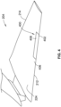
- FIG. 4 is a perspective view of the lower blade 204 of FIGS. 1-3 having an example repair doubler 400 disclosed herein to cover the damaged area 300 of FIG. 3 .
- the repair doubler 400 of the illustrated example can seal or cover the damaged area 300 of FIG. 3 without requiring special tooling and/or mechanical fasteners (e.g., screws or rivets).
- the repair doubler 400 disclosed herein allows for the repair to be performed at any location (e.g., anywhere in the world) such as airports that do not carry special tooling for such repairs.
- repairs to monocoque and/or semi-monocoque assemblies require special tooling such as metal forming tools.
- examples disclosed herein do not require any special tooling and the repair doubler 400 can be hand formed to meet an aerodynamic contour of the monocoque and/or semi-monocoque structure to which the repair doubler is coupled.
- the repair doubler 400 includes a contour 402 (e.g., a shape or profile) that is substantially similar (e.g., complementary) to a contour 406 (e.g., a shape or profile) of the leading edge 212.
- the contour 402 is accomplished by hand forming a doubler plate 408 over the damaged area 300 ( FIG. 3 ).
- the doubler plate 408 is a pliable sheet of material (e.g., a thin sheet of material or sheet metal) that can be formed (e.g., hand formed) or bent to conform to a shape of a portion of the lower blade 204 (e.g., or other airfoil structure).
- FIG. 5 is another perspective view of the example lower blade 204 and the example repair doubler 400 of FIG. 4 .
- the doubler plate 408 e.g., a sheet of material
- the repair doubler 400 and/or doubler plate 408 of the illustrated example has a first portion 501 positioned on the upper skin 222, a second portion 503 positioned on the lower skin 224, and a third portion 505 positioned on or around the leading edge 212 of the lower blade 204.
- the repair doubler 400 and/or the doubler plate 408 of the illustrated example has a curved or arcuate profile that conforms or is complementary to the shape of the upper skin 222, the lower skin 224 and the leading edge 212.
- the doubler plate 408 has a shape that is similar to at least a portion of a shape of an airfoil.
- the repair doubler 400 and/or doubler plate 408 of the illustrated example has a substantially smooth curvature or arcuate profile.
- the repair doubler 400 and/or doubler plate 408 of the illustrated example has a C-shape profile.
- the doubler plate 408 (e.g., the sheet of material) of the illustrated example couples and/or attaches to a skin 502 of the lower blade 204 via a paste, adhesive and/or sealant.
- the doubler plate 408 is hand formed (e.g., without use of forming tools) to provide the contour 402 substantially complementary to the contour 406 of the leading edge 212.
- the doubler plate 408 can initially have a flat, square or rectangular shape.
- the doubler plate 408 is bent or formed by an operator's hands over a portion of the leading edge 212 to conform the doubler plate 408 to a shape substantially similar to the shape of the leading edge 212.
- the doubler plate 408 has a thickness T.
- the thickness T of the doubler plate 408 ranges between approximately 1.016 mm (0.040 inches) to approximately 2.032 mm (0.080 inches).
- the thickness T is approximately 1.6 mm (0.063 inches).
- the doubler plate 408 can have a thickness T that is less than 1.016 mm (0.04 inches) (e.g., 0.254 mm / 0.01 inches).
- the doubler plate 408 of the illustrated example is substantially light weight and, thus, does not add significant weight to the aircraft. Thus, the doubler plate 408 has a negligible effect on fuel efficiency and/or weight.
- the doubler plate 408 of the illustrated example is a pliable sheet of material.
- the doubler plate 408 can be sheet metal.
- the doubler plate 408 is a single piece or a uniform piece of sheet metal.
- the doubler plate 408 can be a pliable plastic (e.g., vinyl), a pliable wood, a pliable metal, and/or any other material that can be bent or shaped to conform to an airfoil structure(s).
- the doubler plate 408 can include aluminum (e.g., 7075-T6 clad and/or bare sheet aluminum), galvanized steel, sheet metal, corrosion resistant steel (CRES), titanium, thermoplastics, pre-cured composites, alloys and/or any other material(s) or alloy(s).
- aluminum e.g., 7075-T6 clad and/or bare sheet aluminum
- CRES corrosion resistant steel
- titanium thermoplastics, pre-cured composites, alloys and/or any other material(s) or alloy(s).
- the doubler plate 408 covers the damaged area 300 and overlaps the skin 502 adjacent the damaged area 300. Because the doubler plate 408 is shaped to conform to a shape of the leading edge 212 (e.g., an airfoil shape), the doubler plate 408 forms a portion of an outer surface or skin (e.g., the skin 502) of the lower blade 204. In other words, an edge or perimeter 508 (e.g., an end) of the doubler plate 408 engages (e.g., directly engages) the winglet 120 (e.g., the skin).
- a shape of the leading edge 212 e.g., an airfoil shape
- an edge or perimeter 508 e.g., an end
- the doubler plate 408 engages (e.g., directly engages) the winglet 120 (e.g., the skin).
- the perimeter 508 of the first portion 501 of the doubler plate 408 engages or overlaps the upper skin 222 (e.g., adjacent the damaged area 300)
- the perimeter 508 of the second portion 503 of the doubler plate 408 engages or overlaps the lower skin 224 (e.g., adjacent the damaged area 300)
- the perimeter 508 of the third portion 505 of the doubler plate 408 engages or overlaps the leading edge 212 (e.g., adjacent the damaged area 300).
- a tape or seal (e.g., the tape 604 of FIG. 6 ) (e.g., a layer of tape) is positioned at least partially along a portion of an interface 506 between the perimeter 508 of the doubler plate 408 and a perimeter or an edge 510 (e.g., a cutout) of the skin 502 adjacent the damaged area 300.
- the doubler plate 408 overlaps the skin 502 (e.g., the edge 510 of the damaged area 300) by an overlap thickness X.
- the overlap thickness X can be approximately between about 3.81 cm (1.5 inches) and about 7.62 cm (3 inches) (e.g., 5.08 cm / 2 inches).
- the overlap thickness X can be any other suitable thickness greater than about 3.81 cm (1.5 inches).
- two or more layers of tape can be applied.
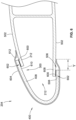
- FIG. 6 illustrates an example cross-sectional view of the lower blade 204 and the example repair doubler 400 of FIG. 4 .
- the repair doubler 400 is positioned over the damaged area 300 and coupled and/or attached to the skin 502 adjacent the leading edge 212.
- the repair doubler 400 is coupled and/or attached to the skin 502 via an adhesive 600.
- the adhesive 600 is placed between the doubler plate 408 and the skin 502 of the leading edge 212.
- the doubler plate 408 overlaps the leading edge 212 of the lower blade 204 adjacent an edge 602 (e.g., a point) of the damaged area 300 adjacent the leading edge 212.
- the adhesive 600 includes a paste, adhesive, sealant, structural glue, etc.
- the adhesive 600 is added to a bottom or rear side 610 of the doubler plate 408 and/or a surface 612 of the skin 502. In some examples, the adhesive 600 is added to at a portion of at least one of the perimeter 508 of the doubler plate 408 or the perimeter 508 of the skin 502 adjacent or outlining the damaged area 300.
- the example repair doubler 400 further includes the layer of tape 604 positioned over at least a portion of the interface 506 of the doubler plate 408 and the skin 502. In some examples, the tape 604 overlaps an edge 608 of the skin 502 by the length Y (e.g., an overlap of approximately 5.08 cm / 2 inches). In other examples, the tape 604 covers an entirety of the perimeter 508 ( FIG.
- the tape 604 covers an entirety of the doubler plate 408 (e.g., an entire surface area or exposed surface of the doubler plate 408).
- the layer of tape 604 can be an aluminum pressure-sensitive tape, aircraft speed tape (e.g., aluminum speed tape), foil tape, etc.
- the doubler plate 408 is a single or unitary sheet. In other examples, the doubler plate 408 includes a plurality of sheets coupled together via adhesive.
- FIG. 7 is a cross-sectional view of another example repair doubler 700 disclosed herein.
- Many of the components of the example repair doubler 700 of FIG. 7 are substantially similar or identical to the components of the repair doubler 400 described above in connection with FIGS. 4-6 . As such, those components will not be described in detail again below. Instead, the interested reader is referred to the above corresponding descriptions for a complete written description of the structure and operation of such components. To facilitate this process, similar or identical reference numbers will be used for like structures in FIG. 7 as used in FIGS. 1-6 .
- the repair doubler 700 of the illustrated example is coupled and/or attached to the skin 502 of the lower blade 204 via adhesive 600.
- the repair doubler 700 of the illustrated example includes a doubler plate 702, a first layer of tape 604, a second layer of tape 704, and adhesive 600.
- the doubler plate 702 of the illustrated example includes a first sheet of material (e.g., sheet metal) or first doubler plate 706 and a second sheet of material (e.g., sheet metal) or a second doubler plate 708.
- first sheet of material e.g., sheet metal
- first doubler plate 706 e.g., sheet metal
- second sheet of material e.g., sheet metal
- the doubler plate 702 can include a plurality of doubler plates or sheets of material (e.g., more than two sheets, three doubler plates or sheets of material, six doubler plates or sheets of material, etc.).
- the first doubler plate 706 and the second doubler plate 708 are bonded and/or attached via an adhesive 709 (e.g., structural glue, sealant, paste, etc.).
- the adhesive 709 is added to a first abutting end 710 of the first doubler plate 706 and/or a second abutting end 712 of the second doubler plate 708.
- the first and second doubler plates 706, 708 are bonded together and positioned at the leading edge 212 forming an airfoil shape.
- a layer of tape (e.g., the tape 604, 704) can be applied to a seam formed between the abutting ends 710, 712.
- the tape can be applied to the seam in addition to or instead of the adhesive 709.
- Employing the first doubler plate 706 and the second doubler plate 708 e.g., multiple doubler plates) facilitates formation of the doubler plate 702 to a shape of the lower blade 204.
- the first doubler plate 706 is formed or bent along the upper skin 222 of the lower blade 204 and a portion of the leading edge 212 adjacent the damaged area 300.
- the second doubler plate 708 is formed or bent along the lower skin 224 of the lower blade 204 and a portion of the leading edge 212 adjacent the damaged area 300.
- the first doubler plate 706 and the second doubler plate 708 can be jointed at respective abutting ends 710, 712 to define the doubler plate 702 to cover the damaged area 300 of the leading edge 212 of the lower blade 204.
- the sizes and shapes of the first and second doubler plates 706, 708 can vary. In some examples, the shape of the first and second doubler plates 706, 708 are rectangular or flat and are bent during formation of the first and second doubler plates 706, 708. In other examples, the shape of the first and second doubler plates 706, 708 are polygonal.
- the first and second doubler plates 706, 708 can be constructed from a variety of materials, including, but not limited to, aluminum (e.g., 7075-T6 clad and/or bare sheet aluminum), galvanized steel, sheet metal, corrosion resistant steel (CRES), titanium, thermoplastics, pre-cured composites and/or any other material that can conform to a shape of the leading edge 212 of an airfoil.
- the first and second doubler plates 706, 708 can be constructed from the same or different materials.
- the example repair doubler 700 further includes the first layer of tape 604 positioned over at least a portion of an interface 506 of the doubler plate 702 and an edge 608 of the skin 502.
- the second layer of tape 704 is positioned over at least a portion of the interface 506 of the doubler plate 702 and the edge 608 of the skin 502.
- the first layer of tape 604 and the second layer of tape 704 can be aluminum pressure-sensitive tape, speed tape, foil tape, aircraft speed tape, etc.
- the first layer of tape 604 and the second layer of tape 704 can be the same or different materials.
- FIG. 7 shows two layers of tape 604, 704, the examples herein shall not be limited thereto.
- the repair doubler 700 includes more than two layers of tape 604, 704 (e.g., three layers of tape, six layers of tape, etc.).
- the second layer of tape 704 can be positioned in an offset or overlapping relationship with the first layer of tape 604.
- the second layer of tape 704 can overlap the first layer of tape 604 by a distance of approximately between 2.54 cm (1 inch) and 5.08 cm (2 inches) (e.g., 3.81 cm / one and half inches).
- FIG. 8 is a flowchart representative of an example method 800 of providing the example repair doubler 400 of FIGS. 4-7 to the damaged area 300 without the use of mechanical fasteners (e.g., screws, rivets, etc.) and without requiring any special tooling.
- mechanical fasteners e.g., screws, rivets, etc.
- FIG. 8 many other methods can be alternatively used.
- the order of execution of the blocks can be changed, and/or some of the blocks can be combined, divided, re-arranged, omitted, eliminated, and/or implemented in any other way.
- the example method 800 of FIG. 8 begins at block 802, at which a sheet of material is obtained having a contour substantially complementary to a contour of an airfoil.
- the airfoil corresponds to the leading edge 212 or the trailing edge 210, 214 of FIGS. 2-7 .
- the sheet of material corresponds to the doubler plate 408 of FIGS. 4-7 .
- a contour of the sheet of material is obtained by hand forming the sheet of material over the airfoil.
- the doubler plate 408 can initially have a substantially flat, square or rectangular shape.
- the doubler plate 408 hand formed over the leading edge 212 adjacent the damaged area 300 to change the shape of the doubler plate 408 from a substantially flat, square or rectangular shape to a contour substantially similar to the contour of the leading edge 212.
- the bent doubler plate 408 is slid and/or shifted over the damaged area 300 of the leading edge 212 to cover or overlap the damaged area 300.
- the doubler plate 408 can be pre-formed or can already have an airfoil shape. Such configuration eliminates the need for an operator to form the doubler plate 408.
- substantially complementary means that the sheet of material has a similar contour (e.g., radius of curvature within plus or minus 10%) as a leading edge of an airfoil, wing or blade (such as, a vertical stabilizer, a horizontal stabilizer, a winglet, etc.).
- a tool is used to form the contour shape.
- an adhesive is applied to at least one of a rear side of the sheet material or a skin of an airfoil.
- the adhesive corresponds to the adhesive 600 of FIG. 6 .
- the adhesive is applied to the rear side 610 of the doubler plate 408 and/or the surface 612 of the skin 502.
- the adhesive is applied to at least a portion of a perimeter the rear side 610 of the doubler plate 408 and/or the surface 612 of the skin 502 adjacent or surrounding a perimeter of the damaged area 300 (e.g., a cutout).
- the adhesive is applied to at least an entire perimeter the rear side 610 of the doubler plate 408 and/or the surface 612 of the skin 502 adjacent the damaged area 300.
- the sheet of material is coupled to the airfoil.
- the sheet of material is coupled to the leading edge over (e.g., to cover) the damaged area 300.
- tape is applied and/or coupled over at least a portion of the sheet material and the skin.
- the tape 604 is applied to the doubler plate 408 and the skin 502. Specifically, the tape 604 is applied along at least a portion of the perimeter 508 of the doubler plate 408.
- the example method 800 of FIG. 8 ends, and the repair doubler is completed allowing the aircraft to operate until a permanent repair can be completed.
- the repair doubler disclosed herein can provide a temporary fix that enables the aircraft to operate for six months or 250 cycles, whichever comes first.
- FIG. 9 is another flowchart representative of another example method 900 of manufacturing the example repair doubler 700 of FIG. 7 without the use of fasteners and without requiring any special tooling.
- the example method of manufacture is described with reference to the flowchart illustrated in FIG. 9 , many other methods can be alternatively used.
- the order of execution of the blocks can be changed, and/or some of the blocks can be combined, divided, re-arranged, omitted, eliminated, and/or implemented in any other way.
- the example method 900 of FIG. 9 begins at block 902, at which a first sheet of metal is bent about a first portion of an airfoil (e.g., a leading edge of a wing) adjacent to a damaged portion of the airfoil.
- a first sheet of metal is bent about a first portion of an airfoil (e.g., a leading edge of a wing) adjacent to a damaged portion of the airfoil.
- the first doubler plate 706 is bent or formed along a first portion of the leading edge 212 of the lower blade 204.
- the first doubler plate 706 is bent over a portion of the upper skin 222 of the lower blade 204 and a portion of the leading edge 212.
- a second sheet of metal is bent about a second portion of the airfoil adjacent to the damaged portion of the airfoil.
- the second doubler plate 708 is bent or formed along a second portion of the leading edge 212 of the lower blade 204.
- the second doubler plate 706 is bent over a portion of the lower skin 224 of the lower blade 204 and a portion of the leading edge 212.
- the first and second sheet of metal is bent by hand about the first and second portion of the leading edge, respectively.
- One aspect of bending the first and second sheet of metal e.g., the doubler plates 706, 708) by hand is that the process does not require any special tooling so that the repair can be completed in remote locations.
- first and second sheet of metal can be formed over a complementary (same as leading edge) shaped tool.
- first and second sheets of material can be pre-formed via the complementary tool.
- the first sheet metal and the second sheet metal conform to a shape of the airfoil.
- an adhesive is added to at least one of a perimeter of the first sheet metal or a perimeter of the airfoil adjacent to the damaged portion to be covered by the first sheet metal.
- adhesive 600 is applied to a rear side or surface adjacent a perimeter edge of the first doubler plate 706 and/or on the skin 502 of the leading edge 212 adjacent a perimeter edge of the damaged area 300 to be covered by the first doubler plate 706.
- an adhesive is added to at least one of a perimeter of the second sheet metal or a perimeter of the airfoil adjacent to the damaged portion to be covered by the second sheet metal.
- adhesive 600 is applied to a rear side or surface adjacent a perimeter edge of the second doubler plate 708 and/or on the skin 502 of the leading edge 212 adjacent a perimeter edge of the damaged area 300 to be covered by the second doubler plate 708.
- an adhesive is added to at least a first abutting end of the first sheet metal or a second abutting end of the second sheet metal.
- adhesive 709 is added to abutting ends 710, 712 of the respective first doubler plate 706 and the second doubler plate 708 to form the doubler plate 702.
- adhesive 709 is added to only the abutting end 710 or the abutting end 712.
- the example method 900 includes the first sheet metal and the second sheet metal, however, the examples shall not be limited thereto.
- the method 900 can include the doubler plate having more than two sheets of material or metal (e.g., three sheets, four sheets, etc.) that can be joined together as a single doubler plate.
- the first sheet metal and the second sheet metal are attached to the airfoil.
- the first sheet metal 7 the doubler plate 702 is fixed, coupled or attached to the skin 502 via the adhesive 600.
- the doubler plate 702 is positioned over the damaged area 300 to cover the damaged area 300.
- the doubler plate 702 forms an outer surface of the airfoil and/or the leading edge 212 of the lower blade 204.
- the abutting ends 710, 712 engage or couple together to form the doubler plate 702.
- the first sheet metal is attached to the airfoil prior to the second sheet metal.
- the second sheet metal is attached to the airfoil prior to the first sheet metal.
- the first sheet metal is attached to the second sheet metal to form a doubler plate and then the first sheet metal and the second sheet metal are attached to the airfoil together or simultaneously.
- tape is coupled to at least a portion of a perimeter edge of the doubler plate and the airfoil.
- the first layer of tape 604 is applied to the doubler plate 702 and a portion of the skin 502 adjacent the perimeter edge of the doubler plate 702.
- the second layer of tape 704 is applied to the first layer of tape 604 and/or the skin 502.
- the example method 900 of FIG. 9 ends, and the repair doubler is completed allowing the aircraft to operate normally until a permanent repair can be completed. In some examples, the repair doubler enables aircraft operation for six months or 250 cycles, whichever comes first.
- each example repair doubler e.g., the repair doubler 400, 700
- any of the features described above and/or depicted in the drawings can be combined with any of the examples, in addition to or in substitution for any of the other features of those examples.
- One example's features are not mutually exclusive to another example's features. Instead, the scope of this disclosure encompasses any combination of any of the features.
- A, B, and/or C refers to any combination or subset of A, B, C such as (1) A alone, (2) B alone, (3) C alone, (4) A with B, (5) A with C, (6) B with C, or (7) A with B and with C.
- the phrase "at least one of A and B" is intended to refer to implementations including any of (1) at least one A, (2) at least one B, or (3) at least one A and at least one B.
- the phrase "at least one of A or B" is intended to refer to implementations including any of (1) at least one A, (2) at least one B, or (3) at least one A and at least one B.
- the phrase "at least one of A and B" is intended to refer to implementations including any of (1) at least one A, (2) at least one B, or (3) at least one A and at least one B.
- the phrase "at least one of A or B" is intended to refer to implementations including any of (1) at least one A, (2) at least one B, or (3) at least one A and at least one B.
- example systems, apparatus, articles of manufacture, and methods have been disclosed that produce a repair for monocoque assemblies that can completed quickly and in remote location.
- the examples disclosed herein do not require fasteners or special tooling.
- the example repairs disclosed herein are lightweight and do not require the removal of the winglet.
- the examples disclosed herein use standard repair materials which allow for quick repair turnarounds.
- Disclosed systems, apparatus, articles of manufacture, and methods that save time and cost of repairing damaged monocoque and/or semi-monocoque assemblies described herein.
- Disclosed systems, apparatus, articles of manufacture, and methods are accordingly directed to one or more improvement(s) in the operation of a machine such as a computer or other electronic and/or mechanical device.
- Example methods, apparatus, systems, and articles of manufacture to repair monocoque or semi-monocoque structures are disclosed herein.
Landscapes
- Engineering & Computer Science (AREA)
- Aviation & Aerospace Engineering (AREA)
- Mechanical Engineering (AREA)
- Manufacturing & Machinery (AREA)
- Transportation (AREA)
Abstract
Description
- This disclosure relates generally to aircraft and, more particularly, to methods and apparatus to repair composite airfoil structures.
- Many aircraft use a monocoque and/or semi-monocoque structures to carry primary stresses and/or maintain rigidity of a wing leading edge, winglet and/or wingtip of the aircraft. The monocoque and/or semi-monocoque structures can be susceptible to impact damage and require repair for aerodynamic requirements of an aircraft.
- According to a first aspect, the disclosure relates to an apparatus to repair a semi-monocoque wing. The apparatus comprises a doubler plate configured to be coupled to a skin of the semi-monocoque wing via a first adhesive, the doubler plate having a contour substantially complementary to a contour of a leading edge of the semi-monocoque wing, and a layer of tape positioned at least partially along at least a portion of an interface between an edge of the doubler plate and the leading edge of the skin.
- The doubler plate may include a first doubler plate attached to a second doubler plate via a second adhesive.
- The tape may overlap at least one of the edge of the doubler plate or the leading edge of the skin by, for instance, a range of about 3.81 cm (1.5 inches) and about 7.62 cm (3 inches).
- The first adhesive may include at least one of adhesive, paste or sealant.
- The doubler plate may have a thickness between approximately 1.016 mm (0.040 inches) and approximately 2.032 mm (0.080 inches).
- The doubler plate may include aluminum.
- The doubler plate may include galvanized steel.
- The tape may be speed tape.
- The wing may be a winglet and the leading edge may be located on a lower blade of the winglet.
- The wing may be a vertical stabilizer and the leading edge may be on the vertical stabilizer.
- According to a second aspect, the disclosure relates to a method to repair a semi-monocoque wing. The method includes: obtaining a sheet of material having a contour substantially complementary to a contour of a leading edge of the semi-monocoque wing; applying adhesive to at least one of a rear side of the sheet of material or a skin of the semi-monocoque wing; coupling the sheet of material over a portion of the leading edge of the semi-monocoque wing to couple the sheet of material and the skin via the adhesive; and applying a tape over at least a portion of the sheet of material and the skin.
- The coupling of the sheet of material may include positioning the sheet of material over a damaged portion of the leading edge of the wing. Preferably, the obtaining of the sheet of material includes bending the sheet of material over a portion of the leading edge of the wing adjacent the damaged portion to shape the sheet of material substantially complementary to the shape of the leading edge.
- The coupling of the tape may include applying the tape along an entirety of an interface between an edge of the sheet of material and the leading edge of the skin.
- The sheet of material may include a first sheet of material attached to a second sheet of material via a second adhesive.
- The sheet of material may include aluminum.
- The tape may overlap the skin, for instance by a range of about 3.81 cm (1.5 inches) and about 7.62 cm (3 inches).
- According to a third aspect, the disclosure relates to method to repair a semi-monocoque wing, the method comprising: bending a first sheet metal about a first portion of a leading edge of a wing adjacent a damaged portion of the leading edge; bending a second sheet metal about a second portion of the leading edge of the wing adjacent the damaged portion of the leading edge, the second portion different than the first portion; adding adhesive to at least one of abutting ends of the first sheet metal and the second sheet metal to couple the first sheet metal and the second sheet metal to form a doubler plate, the first sheet metal and the second sheet metal forming an airfoil shape complementary to an airfoil shape of the leading edge of the wing when the first sheet metal is coupled to the second sheet metal; applying adhesive to a least one of a perimeter of the doubler plate or a perimeter of a skin of the wing adjacent the damaged portion; attaching the doubler plate to the skin of the wing; and coupling tape to at least a portion of a perimeter edge of the doubler plate and the skin adjacent the perimeter edge of the doubler plate.
- The attaching of the tape may include applying the tape along an entirety of the perimeter of the doubler plate and the skin of the wing adjacent to the damaged portion.
- The tape may overlap a range of, for instance, about 3.81 cm (1.5 inches) and about 7.62 cm (3 inches) on the skin adjacent the perimeter of the doubler plate.
-
-
FIG. 1 is a perspective view of an example aircraft having example repairable structures in accordance with teachings of this disclosure. -
FIG. 2 is a perspective view of an example winglet of the example aircraft ofFIG. 1 in an operable or non-damaged state. -
FIG. 3 is a perspective view of the example winglet of the example aircraft ofFIGS. 1 and2 in an example non-operable or damaged state. -
FIG. 4 is a perspective view of the example winglet ofFIG. 3 being repaired with a repair doubler in accordance with teachings of this disclosure. -
FIG. 5 is a perspective view of the example winglet ofFIG. 4 in an example repaired or operable state. -
FIG. 6 is an example cross-sectional view of the example repair doubler and the example winglet ofFIG. 5 . -
FIG. 7 is a cross-sectional view of another example repair doubler disclosed herein. -
FIG. 8 is a flowchart representative of an example method of manufacturing the example repair doubler ofFIGS. 4-6 . -
FIG. 9 is another flowchart representative of another example method of manufacturing the example repair doubler ofFIG. 7 . - In general, the same reference numbers will be used throughout the drawing(s) and accompanying written description to refer to the same or like parts. The figures are not necessarily to scale. Instead, the thickness of the layers or regions may be enlarged in the drawings. Although the figures show layers and regions with clean lines and boundaries, some or all of these lines and/or boundaries may be idealized. In reality, the boundaries and/or lines may be unobservable, blended, and/or irregular.
- As used herein, unless otherwise stated, the term "above" describes the relationship of two parts relative to Earth. A first part is above a second part, if the second part has at least one part between Earth and the first part. Likewise, as used herein, a first part is "below" a second part when the first part is closer to the Earth than the second part. As noted above, a first part can be above or below a second part with one or more of: other parts therebetween, without other parts therebetween, with the first and second parts touching, or without the first and second parts being in direct contact with one another.
- As used in this patent, stating that any part (e.g., a layer, film, area, region, or plate) is in any way on (e.g., positioned on, located on, disposed on, or formed on, etc.) another part, indicates that the referenced part is either in contact with the other part, or that the referenced part is above the other part with one or more intermediate part(s) located therebetween.
- As used herein, connection references (e.g., attached, coupled, connected, and joined) may include intermediate members between the elements referenced by the connection reference and/or relative movement between those elements unless otherwise indicated. As such, connection references do not necessarily infer that two elements are directly connected and/or in fixed relation to each other. As used herein, stating that any part is in "contact" with another part is defined to mean that there is no intermediate part between the two parts.
- Unless specifically stated otherwise, descriptors such as "first," "second," "third," etc., are used herein without imputing or otherwise indicating any meaning of priority, physical order, arrangement in a list, and/or ordering in any way, but are merely used as labels and/or arbitrary names to distinguish elements for ease of understanding the disclosed examples. In some examples, the descriptor "first" may be used to refer to an element in the detailed description, while the same element may be referred to in a claim with a different descriptor such as "second" or "third." In such instances, it should be understood that such descriptors are used merely for identifying those elements distinctly within the context of the discussion (e.g., within a claim) in which the elements might, for example, otherwise share a same name.
- As used herein, "approximately," "substantially" and "about" modify their subjects/values to recognize the potential presence of variations that occur in real world applications. For example, "approximately," "substantially" and "about" may modify dimensions that may not be exact due to manufacturing tolerances and/or other real world imperfections as will be understood by persons of ordinary skill in the art. For example, "approximately" and "about" may indicate such dimensions may be within a tolerance range of +/- 10% unless otherwise specified in the below description. For example, substantially smooth may indicate perfectly smooth or a shape that although deviates from perfectly smooth, provides a smooth surface having characteristic of an almost perfectly smooth surface absent certain non-smooth or rough portions. For example, substantially complementary as used herein indicates that a shape perfectly matches another shape or almost perfectly matches but for some imperfections.
- The construction of composite wings portions, wing leading edges, winglets, wingtips and/or other airfoil structures (e.g., composite airfoil structures) vary from truss structural arrangements to monocoque shell structures and semi-monocoque shell structures. Monocoque and semi-monocoque structures are structural skins that carry tensile and compressive forces. These monocoque and semi-monocoque structures are subject to damage that can be caused by impact with ground support equipment and/or caused by bird strikes during flight. As used herein, a monocoque structure is a structural system in which loads are supported by an object's external skin. As used herein, a semi-monocoque structure refers to a stressed shell structure that is like a monocoque, but which derives at least some of its strength from conventional reinforcement structures including, for example, spars, ribs, stringers, longerons, frames, and/or other structural components.
- Damage to the monocoque and/or semi-monocoque structures can compromise structural integrity and/or affects the aerodynamic characteristics of the structure (e.g., airfoil) that can lead to flutter and/or reduce aircraft efficiency (e.g., increase drag resulting in higher fuel usage). In some scenarios, damage to the structure leaves parts of the aircraft susceptible to water and/or debris damage. Thus, rapid repairs are required to monocoque structures for the aircraft to be operational per aviation standards. However, known techniques to repair monocoque and/or semi-monocoque structures are time consuming and typically require the use of mechanical fasteners and/or a metal forming tool(s). For example, some repairs can take several days, leaving the aircraft inoperable or unusable for this duration of time. Moreover, only certain hubs or airports provide tools necessary for repair and/or inspection.
- Examples described herein allow for quick and simple repairs of winglets, wingtips and/or other airfoil structures without the use of the metal forming tools and/or mechanical fasteners (e.g., rivets, screws, etc.). Examples methods and apparatus disclosed herein allow repairs to aircraft structure(s) that enable the aircraft to operate and/or postpone inspection until the aircraft can fly to a hub or airport with the available tooling to perform permanent repairs and/or inspections. Example methods and apparatus described herein can provide a temporary repair to an aircraft structure (e.g., a monocoque shell structure and semi-monocoque shell structure, an airfoil, etc.) until more durable and permanent repairs can be made to the structure. In some examples, methods and apparatus disclosed herein can postpone a permanent aircraft repair for at least six months, enabling the aircraft to continue normal operation (e.g., flights) without having to decommission the aircraft.
-
FIG. 1 is a perspective view of anexample aircraft 100 havingexample airfoil structures 101 that can be repaired in accordance with teachings of this disclosure. Theairfoil structures 101 of the illustrated example can include various types of airfoils, wing structures, monocoque structures and/or semi-monocoque structures of theaircraft 100. For example, theairfoil structures 101 composed of composite materials can include, but not limited to, wing leading edge(s) 102, horizontal stabilizers leading edge(s) 104,elevators 106, a vertical stabilizer leading edge(s) 108, arudder 110, flaps 112,ailerons 114,slats 118,winglets 120, and/or any other suitable airfoil, monocoque and/or semi-monocoque structure(s). In the depicted example, thewings 102 include thewinglets 120. -
Aircraft 100 is an example aircraft in which a doubler repair disclosed herein can be implemented in accordance with an illustrative example. Theaircraft 100 of the illustrated example is a commercial airliner. However, the example methods and apparatus disclosed herein are not limited to theexample aircraft 100 ofFIG. 1 . In some examples, theaircraft 100 can be a military aircraft, a rotorcraft, a helicopter, an unmanned aerial vehicle, and/or any other suitable vehicle or aircraft. -
FIG. 2 illustrates thewinglet 120 of theexample aircraft 100 ofFIG. 1 . Thewinglet 120 of the illustrated example is a one-piece, bifurcated winglet. For example, thewinglet 120 is part of thewing 102 and is composed of composite material. Thewinglet 120 of the illustrated example has a plurality of blades. The blades of the illustrated example are arranged at an angle with respect to one another. As depicted, thebifurcated winglet 120 of the illustrated example has a first orupper blade 202 arranged at an angle relative to a second orlower blade 204. In some examples, the components within thewinglet 120 have been co-cured to form a single part. As a result, fasteners or other components are not needed to connect one portion (e.g., the upper blade 202) of thewinglet 120 to another portion (e.g., the lower blade 204) of thewinglet 120. Thewinglet 120 has a smooth surface in this illustrative example. Thewinglet 120 is configured to create natural laminar flow. - As depicted, the
winglet 120 includes theupper blade 202, thelower blade 204, and aroot region 206. In this illustrative example, theupper blade 202 has a length that is greater than a length of thelower blade 204. In some illustrative examples, theupper blade 202 and thelower blade 204 can be the same length. As illustrated, theupper blade 202 includes aleading edge 208 and a trailingedge 210, and thelower blade 204 includes aleading edge 212 and a trailingedge 214. Theupper blade 202 has an outboard side orskin 216, an inboard side orskin 218, and atip 220. In a similar fashion, thelower blade 204 has an upper skin 222 (e.g., upper surface), a lower skin 224 (e.g., lower surface), and atip 226. Thelower blade 204 can be a monocoque structure or a semi-monocoque structure. -
FIG. 3 is a perspective view of thelower blade 204 of theexample winglet 120 ofFIGS. 1 and2 having a damaged area 300 (e.g., a cutout). In this example, the damagedarea 300 is located on theleading edge 212 of thelower blade 204. Thelower blade 204 can be susceptible to impact damage (e.g., caused by airport equipment or vehicles) because anoutboard section 302 of thelower blade 204 is positioned at a lower elevation relative to the ground than the wing 102 (FIG. 1 ). In the illustratedFIG. 3 , the damagedarea 300 is trimmed to remove damaged materials fromlower blade 204 that can interfere with repairing thewinglet 120. The damagedarea 300 is a cutout in thelower blade 204 or material that has been removed from thelower blade 204. The damagedarea 300 of the illustrated example has a length L and a depth D. In this example, the length L is approximately 13.97 cm (5.5 inches) and the depth D is approximately 6.35 cm (2.5 inches). However, in other examples, the length L can be approximately between 1.27 cm (0.5 inches) and 30.48 cm (12 inches) and the depth D can be approximately between 1.27 cm (0.5 inches) and 15.24 cm (6 inches). In some examples, the length L and/or the depth D can be any other suitable size. In some examples, the damagedarea 300 to be repaired can be located along another portions of the winglet 120 (e.g., located within two-thirds of theoutboard section 302 of the lower blade 204) and/or any of theother airfoil structures 101 ofFIG. 1 . -
FIG. 4 is a perspective view of thelower blade 204 ofFIGS. 1-3 having anexample repair doubler 400 disclosed herein to cover the damagedarea 300 ofFIG. 3 . Therepair doubler 400 of the illustrated example can seal or cover the damagedarea 300 ofFIG. 3 without requiring special tooling and/or mechanical fasteners (e.g., screws or rivets). As a result, therepair doubler 400 disclosed herein allows for the repair to be performed at any location (e.g., anywhere in the world) such as airports that do not carry special tooling for such repairs. Typically, repairs to monocoque and/or semi-monocoque assemblies require special tooling such as metal forming tools. In contrast, examples disclosed herein do not require any special tooling and therepair doubler 400 can be hand formed to meet an aerodynamic contour of the monocoque and/or semi-monocoque structure to which the repair doubler is coupled. - As illustrated in
FIG. 4 , therepair doubler 400 includes a contour 402 (e.g., a shape or profile) that is substantially similar (e.g., complementary) to a contour 406 (e.g., a shape or profile) of theleading edge 212. In some examples, thecontour 402 is accomplished by hand forming adoubler plate 408 over the damaged area 300 (FIG. 3 ). In the illustrated example, thedoubler plate 408 is a pliable sheet of material (e.g., a thin sheet of material or sheet metal) that can be formed (e.g., hand formed) or bent to conform to a shape of a portion of the lower blade 204 (e.g., or other airfoil structure). In some examples, thecontour 402 is accomplished by hand forming two sheets of material joined together (e.g., near the leading edge 212) via an adhesive or sealant. In other examples, thedoubler plate 408 is a single sheet. In some examples, tooling is used to form the single sheet into a contour shape such as thecontour 406. In some examples, the adhesive includes a paste, adhesive and/or sealant, any combinations thereof, and/or any other material(s). In the illustrated example, thedoubler plate 408 is positioned on theupper skin 222 and thelower skin 224 and wraps around theleading edge 212 of thelower blade 204. -
FIG. 5 is another perspective view of the examplelower blade 204 and theexample repair doubler 400 ofFIG. 4 . As illustrated inFIG. 5 , the doubler plate 408 (e.g., a sheet of material) is positionable over the damaged area 300 (FIG. 3 ) on or around theleading edge 212. For example, therepair doubler 400 and/ordoubler plate 408 of the illustrated example has afirst portion 501 positioned on theupper skin 222, asecond portion 503 positioned on thelower skin 224, and athird portion 505 positioned on or around theleading edge 212 of thelower blade 204. Thus, therepair doubler 400 and/or thedoubler plate 408 of the illustrated example has a curved or arcuate profile that conforms or is complementary to the shape of theupper skin 222, thelower skin 224 and theleading edge 212. Thus, thedoubler plate 408 has a shape that is similar to at least a portion of a shape of an airfoil. Therepair doubler 400 and/ordoubler plate 408 of the illustrated example has a substantially smooth curvature or arcuate profile. Specifically, therepair doubler 400 and/ordoubler plate 408 of the illustrated example has a C-shape profile. The doubler plate 408 (e.g., the sheet of material) of the illustrated example couples and/or attaches to askin 502 of thelower blade 204 via a paste, adhesive and/or sealant. - The
doubler plate 408 is hand formed (e.g., without use of forming tools) to provide thecontour 402 substantially complementary to thecontour 406 of theleading edge 212. For example, thedoubler plate 408 can initially have a flat, square or rectangular shape. Thedoubler plate 408 is bent or formed by an operator's hands over a portion of theleading edge 212 to conform thedoubler plate 408 to a shape substantially similar to the shape of theleading edge 212. To enable thedoubler plate 408 to conform to thecontour 402, thedoubler plate 408 has a thickness T. In some examples, the thickness T of thedoubler plate 408 ranges between approximately 1.016 mm (0.040 inches) to approximately 2.032 mm (0.080 inches). In some examples, the thickness T is approximately 1.6 mm (0.063 inches). In some examples, thedoubler plate 408 can have a thickness T that is less than 1.016 mm (0.04 inches) (e.g., 0.254 mm / 0.01 inches). Thedoubler plate 408 of the illustrated example is substantially light weight and, thus, does not add significant weight to the aircraft. Thus, thedoubler plate 408 has a negligible effect on fuel efficiency and/or weight. - The
doubler plate 408 of the illustrated example is a pliable sheet of material. For example, thedoubler plate 408 can be sheet metal. In the illustrated example, thedoubler plate 408 is a single piece or a uniform piece of sheet metal. In other examples, thedoubler plate 408 can be a pliable plastic (e.g., vinyl), a pliable wood, a pliable metal, and/or any other material that can be bent or shaped to conform to an airfoil structure(s). In some examples, thedoubler plate 408 can include aluminum (e.g., 7075-T6 clad and/or bare sheet aluminum), galvanized steel, sheet metal, corrosion resistant steel (CRES), titanium, thermoplastics, pre-cured composites, alloys and/or any other material(s) or alloy(s). - As illustrated in
FIG. 5 , thedoubler plate 408 covers the damagedarea 300 and overlaps theskin 502 adjacent the damagedarea 300. Because thedoubler plate 408 is shaped to conform to a shape of the leading edge 212 (e.g., an airfoil shape), thedoubler plate 408 forms a portion of an outer surface or skin (e.g., the skin 502) of thelower blade 204. In other words, an edge or perimeter 508 (e.g., an end) of thedoubler plate 408 engages (e.g., directly engages) the winglet 120 (e.g., the skin). For example, theperimeter 508 of thefirst portion 501 of thedoubler plate 408 engages or overlaps the upper skin 222 (e.g., adjacent the damaged area 300), theperimeter 508 of thesecond portion 503 of thedoubler plate 408 engages or overlaps the lower skin 224 (e.g., adjacent the damaged area 300), and theperimeter 508 of thethird portion 505 of thedoubler plate 408 engages or overlaps the leading edge 212 (e.g., adjacent the damaged area 300). - A tape or seal (e.g., the
tape 604 ofFIG. 6 ) (e.g., a layer of tape) is positioned at least partially along a portion of aninterface 506 between theperimeter 508 of thedoubler plate 408 and a perimeter or an edge 510 (e.g., a cutout) of theskin 502 adjacent the damagedarea 300. In the illustrated example, thedoubler plate 408 overlaps the skin 502 (e.g., theedge 510 of the damaged area 300) by an overlap thickness X. In some examples, the overlap thickness X can be approximately between about 3.81 cm (1.5 inches) and about 7.62 cm (3 inches) (e.g., 5.08 cm / 2 inches). In some examples, the overlap thickness X can be any other suitable thickness greater than about 3.81 cm (1.5 inches). In some examples, two or more layers of tape can be applied. -
FIG. 6 illustrates an example cross-sectional view of thelower blade 204 and theexample repair doubler 400 ofFIG. 4 . Therepair doubler 400 is positioned over the damagedarea 300 and coupled and/or attached to theskin 502 adjacent theleading edge 212. Therepair doubler 400 is coupled and/or attached to theskin 502 via an adhesive 600. In some examples, the adhesive 600 is placed between thedoubler plate 408 and theskin 502 of theleading edge 212. As shown inFIG. 6 , thedoubler plate 408 overlaps theleading edge 212 of thelower blade 204 adjacent an edge 602 (e.g., a point) of the damagedarea 300 adjacent theleading edge 212. In some examples, the adhesive 600 includes a paste, adhesive, sealant, structural glue, etc. The adhesive 600 is added to a bottom orrear side 610 of thedoubler plate 408 and/or asurface 612 of theskin 502. In some examples, the adhesive 600 is added to at a portion of at least one of theperimeter 508 of thedoubler plate 408 or theperimeter 508 of theskin 502 adjacent or outlining the damagedarea 300. Theexample repair doubler 400 further includes the layer oftape 604 positioned over at least a portion of theinterface 506 of thedoubler plate 408 and theskin 502. In some examples, thetape 604 overlaps anedge 608 of theskin 502 by the length Y (e.g., an overlap of approximately 5.08 cm / 2 inches). In other examples, thetape 604 covers an entirety of the perimeter 508 (FIG. 5 ) of thedoubler plate 408. In other examples, thetape 604 covers an entirety of the doubler plate 408 (e.g., an entire surface area or exposed surface of the doubler plate 408). In some examples, the layer oftape 604 can be an aluminum pressure-sensitive tape, aircraft speed tape (e.g., aluminum speed tape), foil tape, etc. As illustrated inFIG. 6 , thedoubler plate 408 is a single or unitary sheet. In other examples, thedoubler plate 408 includes a plurality of sheets coupled together via adhesive. -
FIG. 7 is a cross-sectional view of anotherexample repair doubler 700 disclosed herein. Many of the components of theexample repair doubler 700 ofFIG. 7 are substantially similar or identical to the components of therepair doubler 400 described above in connection withFIGS. 4-6 . As such, those components will not be described in detail again below. Instead, the interested reader is referred to the above corresponding descriptions for a complete written description of the structure and operation of such components. To facilitate this process, similar or identical reference numbers will be used for like structures inFIG. 7 as used inFIGS. 1-6 . - The
repair doubler 700 of the illustrated example is coupled and/or attached to theskin 502 of thelower blade 204 viaadhesive 600. Therepair doubler 700 of the illustrated example includes adoubler plate 702, a first layer oftape 604, a second layer oftape 704, and adhesive 600. Thedoubler plate 702 of the illustrated example includes a first sheet of material (e.g., sheet metal) orfirst doubler plate 706 and a second sheet of material (e.g., sheet metal) or a second doubler plate 708. Although this example shows thefirst doubler plate 706 and the second doubler plate 708, the examples herein shall not be limited to two doubler plates. In other examples, thedoubler plate 702 can include a plurality of doubler plates or sheets of material (e.g., more than two sheets, three doubler plates or sheets of material, six doubler plates or sheets of material, etc.). In some examples, thefirst doubler plate 706 and the second doubler plate 708 are bonded and/or attached via an adhesive 709 (e.g., structural glue, sealant, paste, etc.). In some examples, the adhesive 709 is added to a firstabutting end 710 of thefirst doubler plate 706 and/or a secondabutting end 712 of the second doubler plate 708. The first andsecond doubler plates 706, 708 are bonded together and positioned at theleading edge 212 forming an airfoil shape. In some examples, a layer of tape (e.g., thetape 604, 704) can be applied to a seam formed between the abutting ends 710, 712. In some examples, the tape can be applied to the seam in addition to or instead of the adhesive 709. Employing thefirst doubler plate 706 and the second doubler plate 708 (e.g., multiple doubler plates) facilitates formation of thedoubler plate 702 to a shape of thelower blade 204. For example, thefirst doubler plate 706 is formed or bent along theupper skin 222 of thelower blade 204 and a portion of theleading edge 212 adjacent the damagedarea 300. Similarly, the second doubler plate 708 is formed or bent along thelower skin 224 of thelower blade 204 and a portion of theleading edge 212 adjacent the damagedarea 300. With thefirst doubler plate 706 conforming to a first portion of theleading edge 212 and the second doubler plate 708 conforming to a second portion of theleading edge 212, thefirst doubler plate 706 and the second doubler plate 708 can be jointed at respective abutting ends 710, 712 to define thedoubler plate 702 to cover the damagedarea 300 of theleading edge 212 of thelower blade 204. - The sizes and shapes of the first and
second doubler plates 706, 708 can vary. In some examples, the shape of the first andsecond doubler plates 706, 708 are rectangular or flat and are bent during formation of the first andsecond doubler plates 706, 708. In other examples, the shape of the first andsecond doubler plates 706, 708 are polygonal. The first andsecond doubler plates 706, 708 can be constructed from a variety of materials, including, but not limited to, aluminum (e.g., 7075-T6 clad and/or bare sheet aluminum), galvanized steel, sheet metal, corrosion resistant steel (CRES), titanium, thermoplastics, pre-cured composites and/or any other material that can conform to a shape of theleading edge 212 of an airfoil. The first andsecond doubler plates 706, 708 can be constructed from the same or different materials. - The
example repair doubler 700 further includes the first layer oftape 604 positioned over at least a portion of aninterface 506 of thedoubler plate 702 and anedge 608 of theskin 502. In the illustrated example, the second layer oftape 704 is positioned over at least a portion of theinterface 506 of thedoubler plate 702 and theedge 608 of theskin 502. In some examples, the first layer oftape 604 and the second layer oftape 704 can be aluminum pressure-sensitive tape, speed tape, foil tape, aircraft speed tape, etc. In other examples, the first layer oftape 604 and the second layer oftape 704 can be the same or different materials. AlthoughFIG. 7 shows two layers oftape repair doubler 700 includes more than two layers oftape 604, 704 (e.g., three layers of tape, six layers of tape, etc.). The second layer oftape 704 can be positioned in an offset or overlapping relationship with the first layer oftape 604. For example, the second layer oftape 704 can overlap the first layer oftape 604 by a distance of approximately between 2.54 cm (1 inch) and 5.08 cm (2 inches) (e.g., 3.81 cm / one and half inches). -
FIG. 8 is a flowchart representative of anexample method 800 of providing theexample repair doubler 400 ofFIGS. 4-7 to the damagedarea 300 without the use of mechanical fasteners (e.g., screws, rivets, etc.) and without requiring any special tooling. Although the example method is described with reference to the flowchart illustrated inFIG. 8 , many other methods can be alternatively used. For example, the order of execution of the blocks can be changed, and/or some of the blocks can be combined, divided, re-arranged, omitted, eliminated, and/or implemented in any other way. - The
example method 800 ofFIG. 8 begins atblock 802, at which a sheet of material is obtained having a contour substantially complementary to a contour of an airfoil. In some examples, the airfoil corresponds to theleading edge 212 or the trailingedge FIGS. 2-7 . In some examples, the sheet of material corresponds to thedoubler plate 408 ofFIGS. 4-7 . In some examples, a contour of the sheet of material is obtained by hand forming the sheet of material over the airfoil. For example, thedoubler plate 408 can initially have a substantially flat, square or rectangular shape. In some instances, thedoubler plate 408 hand formed over theleading edge 212 adjacent the damagedarea 300 to change the shape of thedoubler plate 408 from a substantially flat, square or rectangular shape to a contour substantially similar to the contour of theleading edge 212. After formation of thedoubler plate 408 with the counter of the airfoil orleading edge 212, thebent doubler plate 408 is slid and/or shifted over the damagedarea 300 of theleading edge 212 to cover or overlap the damagedarea 300. In some examples, thedoubler plate 408 can be pre-formed or can already have an airfoil shape. Such configuration eliminates the need for an operator to form thedoubler plate 408. As used herein, substantially complementary means that the sheet of material has a similar contour (e.g., radius of curvature within plus or minus 10%) as a leading edge of an airfoil, wing or blade (such as, a vertical stabilizer, a horizontal stabilizer, a winglet, etc.). In some examples, a tool is used to form the contour shape. - At
block 804, an adhesive is applied to at least one of a rear side of the sheet material or a skin of an airfoil. In some examples, the adhesive corresponds to the adhesive 600 ofFIG. 6 . Referring toFIGS. 4-6 , the adhesive is applied to therear side 610 of thedoubler plate 408 and/or thesurface 612 of theskin 502. In some examples, the adhesive is applied to at least a portion of a perimeter therear side 610 of thedoubler plate 408 and/or thesurface 612 of theskin 502 adjacent or surrounding a perimeter of the damaged area 300 (e.g., a cutout). In some examples, the adhesive is applied to at least an entire perimeter therear side 610 of thedoubler plate 408 and/or thesurface 612 of theskin 502 adjacent the damagedarea 300. - At
block 806, the sheet of material is coupled to the airfoil. In other words, the sheet of material is coupled to the leading edge over (e.g., to cover) the damagedarea 300. - At
block 808, tape is applied and/or coupled over at least a portion of the sheet material and the skin. Referring toFIGS. 5-7 , thetape 604 is applied to thedoubler plate 408 and theskin 502. Specifically, thetape 604 is applied along at least a portion of theperimeter 508 of thedoubler plate 408. After completion ofblock 808, theexample method 800 ofFIG. 8 ends, and the repair doubler is completed allowing the aircraft to operate until a permanent repair can be completed. In some examples, the repair doubler disclosed herein can provide a temporary fix that enables the aircraft to operate for six months or 250 cycles, whichever comes first. -
FIG. 9 is another flowchart representative of anotherexample method 900 of manufacturing theexample repair doubler 700 ofFIG. 7 without the use of fasteners and without requiring any special tooling. Although the example method of manufacture is described with reference to the flowchart illustrated inFIG. 9 , many other methods can be alternatively used. For example, the order of execution of the blocks can be changed, and/or some of the blocks can be combined, divided, re-arranged, omitted, eliminated, and/or implemented in any other way. - The
example method 900 ofFIG. 9 begins atblock 902, at which a first sheet of metal is bent about a first portion of an airfoil (e.g., a leading edge of a wing) adjacent to a damaged portion of the airfoil. Referring toFIG. 7 , thefirst doubler plate 706 is bent or formed along a first portion of theleading edge 212 of thelower blade 204. For instance, thefirst doubler plate 706 is bent over a portion of theupper skin 222 of thelower blade 204 and a portion of theleading edge 212. - At
block 904, a second sheet of metal is bent about a second portion of the airfoil adjacent to the damaged portion of the airfoil. Referring toFIG. 7 , the second doubler plate 708 is bent or formed along a second portion of theleading edge 212 of thelower blade 204. For instance, thesecond doubler plate 706 is bent over a portion of thelower skin 224 of thelower blade 204 and a portion of theleading edge 212. In some examples, the first and second sheet of metal is bent by hand about the first and second portion of the leading edge, respectively. One aspect of bending the first and second sheet of metal (e.g., thedoubler plates 706, 708) by hand is that the process does not require any special tooling so that the repair can be completed in remote locations. However, in some instances the first and second sheet of metal can be formed over a complementary (same as leading edge) shaped tool. In some examples, the first and second sheets of material can be pre-formed via the complementary tool. The first sheet metal and the second sheet metal conform to a shape of the airfoil. - At
block 906, an adhesive is added to at least one of a perimeter of the first sheet metal or a perimeter of the airfoil adjacent to the damaged portion to be covered by the first sheet metal. Referring toFIG. 7 , adhesive 600 is applied to a rear side or surface adjacent a perimeter edge of thefirst doubler plate 706 and/or on theskin 502 of theleading edge 212 adjacent a perimeter edge of the damagedarea 300 to be covered by thefirst doubler plate 706. - At
block 908, an adhesive is added to at least one of a perimeter of the second sheet metal or a perimeter of the airfoil adjacent to the damaged portion to be covered by the second sheet metal. Referring toFIG. 7 , adhesive 600 is applied to a rear side or surface adjacent a perimeter edge of the second doubler plate 708 and/or on theskin 502 of theleading edge 212 adjacent a perimeter edge of the damagedarea 300 to be covered by the second doubler plate 708. - At
block 910, an adhesive is added to at least a first abutting end of the first sheet metal or a second abutting end of the second sheet metal. Referring toFIG. 7 , adhesive 709 is added to abutting ends 710, 712 of the respectivefirst doubler plate 706 and the second doubler plate 708 to form thedoubler plate 702. However, in some examples, adhesive 709 is added to only theabutting end 710 or theabutting end 712. Theexample method 900 includes the first sheet metal and the second sheet metal, however, the examples shall not be limited thereto. In some examples, themethod 900 can include the doubler plate having more than two sheets of material or metal (e.g., three sheets, four sheets, etc.) that can be joined together as a single doubler plate. - At
block 912, the first sheet metal and the second sheet metal are attached to the airfoil. For example, the first sheet metal 7 In some examples, thedoubler plate 702 is fixed, coupled or attached to theskin 502 via the adhesive 600. Thedoubler plate 702 is positioned over the damagedarea 300 to cover the damagedarea 300. In other words, thedoubler plate 702 forms an outer surface of the airfoil and/or theleading edge 212 of thelower blade 204. The abutting ends 710, 712 engage or couple together to form thedoubler plate 702. In some examples, the first sheet metal is attached to the airfoil prior to the second sheet metal. In some examples, the second sheet metal is attached to the airfoil prior to the first sheet metal. In some examples, the first sheet metal is attached to the second sheet metal to form a doubler plate and then the first sheet metal and the second sheet metal are attached to the airfoil together or simultaneously. - At
block 914, tape is coupled to at least a portion of a perimeter edge of the doubler plate and the airfoil. Referring toFIG. 7 , the first layer oftape 604 is applied to thedoubler plate 702 and a portion of theskin 502 adjacent the perimeter edge of thedoubler plate 702. The second layer oftape 704 is applied to the first layer oftape 604 and/or theskin 502. After completion ofblock 912, theexample method 900 ofFIG. 9 ends, and the repair doubler is completed allowing the aircraft to operate normally until a permanent repair can be completed. In some examples, the repair doubler enables aircraft operation for six months or 250 cycles, whichever comes first. - Although each example repair doubler (e.g., the
repair doubler 400, 700) disclosed above have certain features, it should be understood that it is not necessary for a particular feature of one example to be used exclusively with that example. Instead, any of the features described above and/or depicted in the drawings can be combined with any of the examples, in addition to or in substitution for any of the other features of those examples. One example's features are not mutually exclusive to another example's features. Instead, the scope of this disclosure encompasses any combination of any of the features. - "Including" and "comprising" (and all forms and tenses thereof) are used herein to be open ended terms. Thus, whenever a claim employs any form of "include" or "comprise" (e.g., comprises, includes, comprising, including, having, etc.) as a preamble or within a claim recitation of any kind, it is to be understood that additional elements, terms, etc., may be present without falling outside the scope of the corresponding claim or recitation. As used herein, when the phrase "at least" is used as the transition term in, for example, a preamble of a claim, it is open-ended in the same manner as the term "comprising" and "including" are open ended. The term "and/or" when used, for example, in a form such as A, B, and/or C refers to any combination or subset of A, B, C such as (1) A alone, (2) B alone, (3) C alone, (4) A with B, (5) A with C, (6) B with C, or (7) A with B and with C. As used herein in the context of describing structures, components, items, objects and/or things, the phrase "at least one of A and B" is intended to refer to implementations including any of (1) at least one A, (2) at least one B, or (3) at least one A and at least one B. Similarly, as used herein in the context of describing structures, components, items, objects and/or things, the phrase "at least one of A or B" is intended to refer to implementations including any of (1) at least one A, (2) at least one B, or (3) at least one A and at least one B. As used herein in the context of describing the performance or execution of processes, instructions, actions, activities and/or steps, the phrase "at least one of A and B" is intended to refer to implementations including any of (1) at least one A, (2) at least one B, or (3) at least one A and at least one B. Similarly, as used herein in the context of describing the performance or execution of processes, instructions, actions, activities and/or steps, the phrase "at least one of A or B" is intended to refer to implementations including any of (1) at least one A, (2) at least one B, or (3) at least one A and at least one B.
- As used herein, singular references (e.g., "a", "an", "first", "second", etc.) do not exclude a plurality. The term "a" or "an" object, as used herein, refers to one or more of that object. The terms "a" (or "an"), "one or more", and "at least one" are used interchangeably herein. Furthermore, although individually listed, a plurality of means, elements, or actions may be implemented by, e.g., the same entity or object. Additionally, although individual features may be included in different examples or claims, these may possibly be combined, and the inclusion in different examples or claims does not imply that a combination of features is not feasible and/or advantageous.
- From the foregoing, it will be appreciated that example systems, apparatus, articles of manufacture, and methods have been disclosed that produce a repair for monocoque assemblies that can completed quickly and in remote location. The examples disclosed herein do not require fasteners or special tooling. Furthermore, the example repairs disclosed herein are lightweight and do not require the removal of the winglet. The examples disclosed herein use standard repair materials which allow for quick repair turnarounds. Disclosed systems, apparatus, articles of manufacture, and methods that save time and cost of repairing damaged monocoque and/or semi-monocoque assemblies described herein. Disclosed systems, apparatus, articles of manufacture, and methods are accordingly directed to one or more improvement(s) in the operation of a machine such as a computer or other electronic and/or mechanical device.
- Example methods, apparatus, systems, and articles of manufacture to repair monocoque or semi-monocoque structures are disclosed herein.
- The following claims are hereby incorporated into this Detailed Description by this reference. Although certain example systems, apparatus, articles of manufacture, and methods have been disclosed herein, the scope of coverage of this patent is not limited thereto. On the contrary, this patent covers all systems, apparatus, articles of manufacture, and methods fairly falling within the scope of the claims of this patent.
Claims (15)
- An apparatus to repair a semi-monocoque wing (102, 120) comprising:a doubler plate (408) configured to be coupled to a skin (222) of the semi-monocoque wing via a first adhesive (600), the doubler plate having a contour (402) substantially complementary to a contour (406) of a leading edge (212) of the semi-monocoque wing; anda layer of tape (604) positioned at least partially along at least a portion of an interface (506) between an edge (508) of the doubler plate and the leading edge of the skin.
- The apparatus as defined in claim 1, wherein the doubler plate includes a first doubler plate (706) attached to a second doubler plate (708) via a second adhesive (709).
- The apparatus as defined in claim 1 or 2, wherein the tape overlaps at least one of the edge of the doubler plate or the leading edge of the skin by a range of about 3.81 cm (1.5 inches) and about 7.62 cm (3 inches).
- The apparatus as defined in any one of claims 1-3, wherein:the first adhesive includes at least one of adhesive, paste or sealant; and/orthe doubler plate has a thickness (T) between approximately 1.016 mm (0.040 inches) and approximately 2.032 mm (0.080 inches).
- The apparatus as defined in any one of claims 1-4, wherein:the doubler plate includes aluminum; and/orthe doubler plate includes galvanized steel.
- The apparatus as defined in any one of claims 1-5, wherein the tape is speed tape.
- The apparatus as defined in any one of claims 1-6, wherein:the wing is a winglet (120) and the leading edge is located on a lower blade (204) of the winglet; orthe wing is a vertical stabilizer (108) and the leading edge is on the vertical stabilizer.
- A method to repair a semi-monocoque wing comprising:obtaining a sheet of material (408, 802) having a contour substantially complementary to a contour (406) of a leading edge (212) of the semi-monocoque wing (102, 120);applying adhesive (600, 804) to at least one of a rear side (610) of the sheet of material (408) or a skin (502) of the semi-monocoque wing;coupling the sheet of material over a portion (300, 806) of the leading edge (212) of the semi-monocoque wing to couple the sheet of material and the skin via the adhesive;applying a tape (604, 808) over at least a portion of the sheet of material and the skin.
- The method as defined in claim 8, wherein the coupling of the sheet of material includes positioning the sheet of material over a damaged portion (300) of the leading edge of the wing.
- The method as defined in claim 9, wherein the obtaining of the sheet of material includes bending the sheet of material over a portion (212) of the leading edge of the wing adjacent the damaged portion to shape the sheet of material substantially complementary to the shape of the leading edge.
- The method as defined in any one of claims 8-10, wherein the coupling of the tape includes applying the tape along an entirety of an interface (506, 508, 510) between an edge of the sheet of material and the leading edge of the skin.
- The method as defined in any one of claims 8-11, wherein the sheet of material includes a first sheet of material (706) attached to a second sheet of material (708) via a second adhesive (709).
- The method as defined in any one of claims 8-12, wherein:the sheet of material includes aluminum; and/orthe tape overlaps the skin by a range of about 3.81 cm (1.5 inches) and about 7.62 cm (3 inches).
- A method to repair a semi-monocoque wing comprising:bending a first sheet metal (706, 902) about a first portion of a leading edge (212) of a wing (102, 120) adjacent a damaged portion (300) of the leading edge;bending a second sheet metal (706, 904) about a second portion of the leading edge of the wing adjacent the damaged portion of the leading edge, the second portion different than the first portion;adding adhesive (709, 910) to at least one of abutting ends (710, 712) of the first sheet metal and the second sheet metal to couple the first sheet metal and the second sheet metal to form a doubler plate (702), the first sheet metal and the second sheet metal forming an airfoil shape complementary to an airfoil shape of the leading edge of the wing when the first sheet metal is coupled to the second sheet metal;applying adhesive (600) to a least one of a perimeter (508) of the doubler plate or a perimeter of a skin (502) of the wing adjacent the damaged portion;attaching the doubler plate to the skin of the wing; andcoupling tape (604) to at least a portion of a perimeter edge (508) of the doubler plate and the skin adjacent the perimeter edge of the doubler plate.
- The method as defined in claim 14, wherein:the attaching of the tape includes applying the tape along an entirety of the perimeter of the doubler plate and the skin of the wing adjacent to the damaged portion; and/orthe tape overlaps a range of about 3.81 cm (1.5 inches) and about 7.62 cm (3 inches) on the skin adjacent the perimeter of the doubler plate.
Applications Claiming Priority (1)
| Application Number | Priority Date | Filing Date | Title |
|---|---|---|---|
| US18/354,994 US12528600B2 (en) | 2023-07-19 | 2023-07-19 | Methods and apparatus to repair composite airfoil structures |
Publications (1)
| Publication Number | Publication Date |
|---|---|
| EP4495015A1 true EP4495015A1 (en) | 2025-01-22 |
Family
ID=91898539
Family Applications (1)
| Application Number | Title | Priority Date | Filing Date |
|---|---|---|---|
| EP24187180.5A Pending EP4495015A1 (en) | 2023-07-19 | 2024-07-08 | Methods and apparatus to repair composite airfoil structures |
Country Status (3)
| Country | Link |
|---|---|
| US (2) | US12528600B2 (en) |
| EP (1) | EP4495015A1 (en) |
| CN (1) | CN119329773A (en) |
Citations (4)
| Publication number | Priority date | Publication date | Assignee | Title |
|---|---|---|---|---|
| US20080159870A1 (en) * | 2006-12-14 | 2008-07-03 | Hontek Corporation | Method and coating for protecting and repairing an airfoil surface using molded boots, sheet or tape |
| US20210061491A1 (en) * | 2019-09-03 | 2021-03-04 | The Boeing Company | Repair Assembly to Repair an Area on a Member of a Vehicle |
| US20220234316A1 (en) * | 2021-01-28 | 2022-07-28 | Airbus Operations Gmbh | Quick-repair patch for renovating external damage, and quick-repair method |
| CN115230984A (en) * | 2021-04-22 | 2022-10-25 | 中国航发商用航空发动机有限责任公司 | Method for repairing damage of windward curved surface type structural part |
Family Cites Families (7)
| Publication number | Priority date | Publication date | Assignee | Title |
|---|---|---|---|---|
| US20040118978A1 (en) * | 2002-12-24 | 2004-06-24 | Anning Bruce D. | Helicopter rotor and method of repairing same |
| US20070062166A1 (en) * | 2005-09-16 | 2007-03-22 | Velasquez Urey Ruben E | Apparatus for manufacture of cover tape |
| US20120163981A1 (en) * | 2010-12-22 | 2012-06-28 | Hong Shek C | Method and coating for protecting and repairing an airfoil surface |
| WO2014081356A1 (en) * | 2012-11-20 | 2014-05-30 | Saab Ab | An airframe leading edge |
| US10744747B2 (en) * | 2015-07-27 | 2020-08-18 | The Boeing Company | Repairing a contoured composite panel |
| DE102019102893B3 (en) * | 2019-02-06 | 2020-02-06 | Dr. Ing. H.C. F. Porsche Aktiengesellschaft | Rear fairing for a road vehicle with a rear view camera |
| US11891174B2 (en) * | 2020-02-05 | 2024-02-06 | The Boeing Company | Repair of structures using unmanned aerial vehicles |
-
2023
- 2023-07-19 US US18/354,994 patent/US12528600B2/en active Active
-
2024
- 2024-07-01 CN CN202410868952.9A patent/CN119329773A/en active Pending
- 2024-07-08 EP EP24187180.5A patent/EP4495015A1/en active Pending
-
2025
- 2025-12-17 US US19/423,726 patent/US20260116580A1/en active Pending
Patent Citations (4)
| Publication number | Priority date | Publication date | Assignee | Title |
|---|---|---|---|---|
| US20080159870A1 (en) * | 2006-12-14 | 2008-07-03 | Hontek Corporation | Method and coating for protecting and repairing an airfoil surface using molded boots, sheet or tape |
| US20210061491A1 (en) * | 2019-09-03 | 2021-03-04 | The Boeing Company | Repair Assembly to Repair an Area on a Member of a Vehicle |
| US20220234316A1 (en) * | 2021-01-28 | 2022-07-28 | Airbus Operations Gmbh | Quick-repair patch for renovating external damage, and quick-repair method |
| CN115230984A (en) * | 2021-04-22 | 2022-10-25 | 中国航发商用航空发动机有限责任公司 | Method for repairing damage of windward curved surface type structural part |
Also Published As
| Publication number | Publication date |
|---|---|
| US20260116580A1 (en) | 2026-04-30 |
| CN119329773A (en) | 2025-01-21 |
| US20250026493A1 (en) | 2025-01-23 |
| US12528600B2 (en) | 2026-01-20 |
Similar Documents
| Publication | Publication Date | Title |
|---|---|---|
| US7980515B2 (en) | Aircraft wing modification and related methods | |
| US10836472B2 (en) | One-piece composite bifurcated winglet | |
| CN105438438B (en) | Composite wing edge attachment and method | |
| US20140286780A1 (en) | Aerogenerator blade tip segment and method of assembly | |
| JP7017353B2 (en) | Aircraft wings, aircraft, and related methods | |
| EP2799330B1 (en) | Protective finish for wing tip devices | |
| EP3816039B1 (en) | Continuous skin leading edge slats | |
| CN107416182B (en) | Wing-shaped body, aircraft, winglet, and method of manufacturing wing-shaped body | |
| US6415510B2 (en) | Method of fabricating leading edge nose structures of aerodynamic surfaces | |
| US12091155B2 (en) | Structural arrangement for strut-braced wing assembly of an aircraft | |
| EP3287360A1 (en) | Aircraft composite wingbox integration | |
| US12134466B2 (en) | Unmanned aerial vehicles including wing capture devices and related methods | |
| US12528600B2 (en) | Methods and apparatus to repair composite airfoil structures | |
| US10040536B2 (en) | Wing structure, stringer structure, and related apparatus and methods of assembly | |
| CN113697085B (en) | Structural composite airfoil with directly coupled front spar and related methods | |
| CN115723949A (en) | High duct type tail structure and forming method thereof | |
| CN113044200A (en) | Novel solar unmanned aerial vehicle layout with connection wings close to space | |
| BROWN, JR et al. | Aeroelastically tailored wing design | |
| Bennett et al. | Design and Fabrication of Marvel II Wings |
Legal Events
| Date | Code | Title | Description |
|---|---|---|---|
| PUAI | Public reference made under article 153(3) epc to a published international application that has entered the european phase |
Free format text: ORIGINAL CODE: 0009012 |
|
| STAA | Information on the status of an ep patent application or granted ep patent |
Free format text: STATUS: THE APPLICATION HAS BEEN PUBLISHED |
|
| AK | Designated contracting states |
Kind code of ref document: A1 Designated state(s): AL AT BE BG CH CY CZ DE DK EE ES FI FR GB GR HR HU IE IS IT LI LT LU LV MC ME MK MT NL NO PL PT RO RS SE SI SK SM TR |
|
| STAA | Information on the status of an ep patent application or granted ep patent |
Free format text: STATUS: REQUEST FOR EXAMINATION WAS MADE |
|
| 17P | Request for examination filed |
Effective date: 20250712 |
|
| STAA | Information on the status of an ep patent application or granted ep patent |
Free format text: STATUS: EXAMINATION IS IN PROGRESS |
|
| 17Q | First examination report despatched |
Effective date: 20260306 |