EP4494957A1 - Method and apparatus for reducing a risk of motion sickness - Google Patents
Method and apparatus for reducing a risk of motion sickness Download PDFInfo
- Publication number
- EP4494957A1 EP4494957A1 EP23187087.4A EP23187087A EP4494957A1 EP 4494957 A1 EP4494957 A1 EP 4494957A1 EP 23187087 A EP23187087 A EP 23187087A EP 4494957 A1 EP4494957 A1 EP 4494957A1
- Authority
- EP
- European Patent Office
- Prior art keywords
- acceleration
- vehicle
- predicted
- occupant
- computer
- Prior art date
- Legal status (The legal status is an assumption and is not a legal conclusion. Google has not performed a legal analysis and makes no representation as to the accuracy of the status listed.)
- Granted
Links
Images
Classifications
-
- B—PERFORMING OPERATIONS; TRANSPORTING
- B60—VEHICLES IN GENERAL
- B60W—CONJOINT CONTROL OF VEHICLE SUB-UNITS OF DIFFERENT TYPE OR DIFFERENT FUNCTION; CONTROL SYSTEMS SPECIALLY ADAPTED FOR HYBRID VEHICLES; ROAD VEHICLE DRIVE CONTROL SYSTEMS FOR PURPOSES NOT RELATED TO THE CONTROL OF A PARTICULAR SUB-UNIT
- B60W30/00—Purposes of road vehicle drive control systems not related to the control of a particular sub-unit, e.g. of systems using conjoint control of vehicle sub-units
- B60W30/02—Control of vehicle driving stability
- B60W30/025—Control of vehicle driving stability related to comfort of drivers or passengers
-
- B—PERFORMING OPERATIONS; TRANSPORTING
- B60—VEHICLES IN GENERAL
- B60Q—ARRANGEMENT OF SIGNALLING OR LIGHTING DEVICES, THE MOUNTING OR SUPPORTING THEREOF OR CIRCUITS THEREFOR, FOR VEHICLES IN GENERAL
- B60Q9/00—Arrangement or adaptation of signal devices not provided for in one of main groups B60Q1/00 - B60Q7/00, e.g. haptic signalling
-
- B—PERFORMING OPERATIONS; TRANSPORTING
- B60—VEHICLES IN GENERAL
- B60W—CONJOINT CONTROL OF VEHICLE SUB-UNITS OF DIFFERENT TYPE OR DIFFERENT FUNCTION; CONTROL SYSTEMS SPECIALLY ADAPTED FOR HYBRID VEHICLES; ROAD VEHICLE DRIVE CONTROL SYSTEMS FOR PURPOSES NOT RELATED TO THE CONTROL OF A PARTICULAR SUB-UNIT
- B60W50/00—Details of control systems for road vehicle drive control not related to the control of a particular sub-unit, e.g. process diagnostic or vehicle driver interfaces
- B60W50/0097—Predicting future conditions
-
- B—PERFORMING OPERATIONS; TRANSPORTING
- B60—VEHICLES IN GENERAL
- B60W—CONJOINT CONTROL OF VEHICLE SUB-UNITS OF DIFFERENT TYPE OR DIFFERENT FUNCTION; CONTROL SYSTEMS SPECIALLY ADAPTED FOR HYBRID VEHICLES; ROAD VEHICLE DRIVE CONTROL SYSTEMS FOR PURPOSES NOT RELATED TO THE CONTROL OF A PARTICULAR SUB-UNIT
- B60W50/00—Details of control systems for road vehicle drive control not related to the control of a particular sub-unit, e.g. process diagnostic or vehicle driver interfaces
- B60W50/08—Interaction between the driver and the control system
- B60W50/14—Means for informing the driver, warning the driver or prompting a driver intervention
-
- B—PERFORMING OPERATIONS; TRANSPORTING
- B60—VEHICLES IN GENERAL
- B60W—CONJOINT CONTROL OF VEHICLE SUB-UNITS OF DIFFERENT TYPE OR DIFFERENT FUNCTION; CONTROL SYSTEMS SPECIALLY ADAPTED FOR HYBRID VEHICLES; ROAD VEHICLE DRIVE CONTROL SYSTEMS FOR PURPOSES NOT RELATED TO THE CONTROL OF A PARTICULAR SUB-UNIT
- B60W50/00—Details of control systems for road vehicle drive control not related to the control of a particular sub-unit, e.g. process diagnostic or vehicle driver interfaces
- B60W50/08—Interaction between the driver and the control system
- B60W50/14—Means for informing the driver, warning the driver or prompting a driver intervention
- B60W50/16—Tactile feedback to the driver, e.g. vibration or force feedback to the driver on the steering wheel or the accelerator pedal
-
- B—PERFORMING OPERATIONS; TRANSPORTING
- B60—VEHICLES IN GENERAL
- B60K—ARRANGEMENT OR MOUNTING OF PROPULSION UNITS OR OF TRANSMISSIONS IN VEHICLES; ARRANGEMENT OR MOUNTING OF PLURAL DIVERSE PRIME-MOVERS IN VEHICLES; AUXILIARY DRIVES FOR VEHICLES; INSTRUMENTATION OR DASHBOARDS FOR VEHICLES; ARRANGEMENTS IN CONNECTION WITH COOLING, AIR INTAKE, GAS EXHAUST OR FUEL SUPPLY OF PROPULSION UNITS IN VEHICLES
- B60K2360/00—Indexing scheme associated with groups B60K35/00 or B60K37/00 relating to details of instruments or dashboards
- B60K2360/16—Type of output information
- B60K2360/167—Vehicle dynamics information
-
- B—PERFORMING OPERATIONS; TRANSPORTING
- B60—VEHICLES IN GENERAL
- B60W—CONJOINT CONTROL OF VEHICLE SUB-UNITS OF DIFFERENT TYPE OR DIFFERENT FUNCTION; CONTROL SYSTEMS SPECIALLY ADAPTED FOR HYBRID VEHICLES; ROAD VEHICLE DRIVE CONTROL SYSTEMS FOR PURPOSES NOT RELATED TO THE CONTROL OF A PARTICULAR SUB-UNIT
- B60W50/00—Details of control systems for road vehicle drive control not related to the control of a particular sub-unit, e.g. process diagnostic or vehicle driver interfaces
- B60W50/08—Interaction between the driver and the control system
- B60W50/14—Means for informing the driver, warning the driver or prompting a driver intervention
- B60W2050/146—Display means
Definitions
- the present disclosure relates to the field of vehicle assistance systems and, more particularly, to an apparatus and a method for reducing a risk of motion sickness from affecting an occupant of the vehicle.
- ADAS Advanced Driver Assistance Systems
- driver assistance systems have been designed to guide the driver and assist them during their journey by automating, improving, or adapting some or all of the tasks related to driving a vehicle.
- driver assistance systems generally rely on sensors to assist the driver throughout their journey and often communicate with a server to receive real-time information along the vehicle's path.
- Modern assistance driver systems also provide additional information related to the path, such as weather conditions, traffic congestion, duration, and disruptions on the road (diversions or lane closures, for example).
- the driver assistance system can also be configured to provide information, including regulatory indications, such as speed limits or the presence of checkpoints.
- Driver assistance may further encompass secondary tasks such as location finding and obstacle detection.
- secondary tasks such as location finding and obstacle detection.
- it enables the anticipation of potential collisions, such as with stationary objects (traffic barriers, signs, or trees, for example) or with moving objects like other vehicles.
- driver assistance systems contribute to user distraction which leads them to no longer be aware of the route to be travelled by the vehicle.
- motion sickness occurs when the central nervous system receives conflicting signals from various sensory systems, including the inner ear, eyes, skin pressure receptors, and muscle/joint sensory receptors.
- Symptoms of motion sickness generally include nausea, dizziness, headaches, sweating and/or vomiting. It may become dangerous for the occupant's health and safety if they have to take control of the vehicle since the driver will not be in full physical control at the time.
- the object of the present invention is to at least substantially address the aforementioned drawbacks.
- the aim of the invention is to provide anticipatory cues that inform in advance the occupant(s) (or passenger(s)) of the vehicle, consciously and/or unconsciously, about its upcoming movements and thus reducing the risk of motion sickness from affecting the occupant(s).
- the present disclosures relates to a computer-implemented method for reducing a risk of motion sickness from affecting an occupant in a moving vehicle, the method comprising:
- the method is referred to hereinafter as the risk reduction method.
- the "predicted at least one acceleration” comprises one predicted acceleration or a plurality of predicted accelerations.
- the term "occupant” may refer to a single occupant of the vehicle or to a plurality of occupants of the vehicle, depending on the number of the passengers inside said vehicle.
- providing information representative of at least the magnitude of a predicted acceleration to be performed during the upcoming movement of the vehicle alerts the occupant that such movement is about to occur and thus helps their central nervous system to match between the perceived and actual upcoming movement of the vehicle.
- the trajectory data comprises at least one obstacle to be avoided by the vehicle and/or traffic condition over the predetermined distance.
- An obstacle may be defined as any object or condition that may cause collision with the vehicle.
- the obstacle can be a stationary object (traffic barriers, signs, or trees, for example) or a moving object such as other vehicles.
- the information is provided to the occupant as at least one of haptic signals and/or visual signals and/or audio signals.
- the information provided to the occupant further comprises a direction of the predicted at least one acceleration, the haptic signals comprising movement of said occupant's seat in the direction of the predicted at least one acceleration.
- Providing the direction of the predicted acceleration is beneficial due to the human body's reliance on multiple sensory cues for perceiving motion. By considering this direction, it becomes possible to analyse how the occupant's body will move when the predicted acceleration occurs. This information can then be communicated to the occupant, helping for the alignment of the perceived motion with the actual motion of the vehicle.
- the haptic signals comprise a vibration of the occupant's seat.
- the haptic signals comprise a vibration of the floor that supports the occupant.
- the haptic signals comprise a vibration of control means configured to control the acceleration of the vehicle.
- the control means refer to mechanisms that the occupant can manipulate to control the vehicle's acceleration, such as pedals or a gear lever.
- providing haptic signals comprise increasing a resistance to movement of the control means.
- the information provided to the occupant further comprises a direction of the predicted at least one acceleration.
- the audio signals are emitted from a side of the vehicle corresponding to a starting point of the predicted at least one acceleration.
- the direction of the predicted at least one acceleration corresponds to the direction of the movement of the occupant's seat.
- the starting point refers then to the beginning of the acceleration vector corresponding to the predicted at least one acceleration.
- the information provided to the occupant further comprises a direction of the predicted at least one acceleration.
- the audio signals are louder when the predicted at least one acceleration is positive than when said acceleration is negative.
- both positive and negative accelerations are associated with a same reference direction. Accordingly, the negative acceleration and the positive acceleration are in opposite directions.
- the audio signals include an artificial acceleration or an artificial deceleration sound.
- the audio signals include an audio speech.
- the visual signals comprise a display of a horizon line and/or a vertical line at an angle depending on a direction of the predicted at least one acceleration.
- the visual signals comprise a display of textual information.
- the visual signals comprise a display of at least one figure which is static or mobile, the speed of the scrolling of said mobile at least one figure being a function of the magnitude of the predicted at least one acceleration.
- the visual signals are displayed on an on-vehicle screen and/or on the road of the trajectory to be travelled and/or on the windscreen of the vehicle and/or on a screen of a portable terminal.
- portable terminal refers to an electronic apparatus that is designed to be carried or moved from one place to another. Examples of portable devices include smartphones, tablets or laptops.
- the visual signals can also be displayed on the road ahead of and/or behind the moving vehicle. This allows the occupant of the vehicle, whether their field of vision is towards the front or the rear side of the vehicle, to read the information that is representative of at least the magnitude of the predicted acceleration. In this way, the occupant can be alerted to an upcoming movement of the vehicle, regardless of the direction they are looking in.
- the visual signals can be projected onto the road by using for example well-known optical projection techniques to superimpose the visual information on the road, ensure that the information is properly aligned with the road and appears in the correct perspective to the occupant.
- Such projection reduces the need for the occupant and especially the driver to look away from the road and thus enhances the driving safety.
- the visual signals are displayed overlapping or adjacent to the displayed trajectory to be travelled by the vehicle.
- the predetermined time is greater than or equal to 0.5 seconds.
- the information representing at least the magnitude of the predicted acceleration(s) is provided to them prior to its occurrence.
- the predetermined time is then selected to allow sufficient awareness for the vehicle occupant regarding the upcoming vehicle movement, thus reducing the risk of motion sickness from affecting the occupant.
- the information is not provided in real-time, but in anticipation of real-time.
- the predetermined time may also be equal to 1 second before the upcoming movement.
- the predetermined distance is lower than or equal to 100 meters.
- the size of the collected trajectory data may be limited to ensure faster processing and prompt provision of the information representing at least the magnitude of the predicted acceleration.
- collecting the trajectory data over a short distance, such as 100 meters or less is advantageous to constrain the dataset size.
- the present disclosure further relates to a computer program set including instructions for executing the steps of the above-described computer-implemented method when said program set is executed by at least one computer.
- This program set can use any programming language and take the form of source code, object code, or a code intermediate between source code and object code, such as a partially compiled form or any other desirable form.
- the present disclosure further relates to an apparatus for reducing a risk of motion sickness from affecting an occupant in a moving vehicle, the apparatus comprising:
- the apparatus referred to hereinafter as the risk reduction apparatus may be configured to carry out the above-mentioned risk reduction method and may have part or all of the above-described features.
- the risk reduction apparatus may have the hardware structure of a computer.
- the present disclosure also relates to a vehicle comprising an apparatus for reducing a risk of motion sickness, as described above.
- vehicle may be directed to an apparatus capable of transporting people from one location to another, such as a car or a motorcycle.
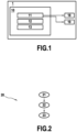
- FIG. 1 shows a block diagram of a risk reduction apparatus 10 comprising a receiving module 11, a predicting module 12, and an information module 13 according to embodiments of the present disclosure.
- the risk reduction apparatus 10 may be located inside a vehicle 1 which may be, without limitation, autonomous or semi-autonomous vehicles.
- the risk reduction apparatus 10 may be partially or totally located outside the vehicle 1.
- functions of the receiving module 11, the predicting module 12 and the information module 13 are executed via cloud computing.
- functions of the receiving module 11 and the predicting module 12 are executed via cloud computing. Accordingly, the functions of the information module 13 are then executed inside the vehicle 1.
- the risk reduction apparatus 10 may be configured to reduce a risk of motion sickness from affecting an occupant in the vehicle 1 when it is in motion. To this end, the risk reduction apparatus 10 provides anticipatory cues that inform in advance the occupant (or passenger) of the vehicle 1, consciously and/or unconsciously, about its upcoming movements and thus reduces the risk of motion sickness from affecting the occupant.
- Such vehicle 1 may be directed to an apparatus capable of transporting people from one location to another, such as a car or a motorcycle, and may be categorized into different levels based on the extent of automation and human involvement in the driving tasks.
- the risk reduction apparatus 10 may comprise an electronic circuit, a processor (shared, dedicated, or group), a combinational logic circuit, a memory that executes one or more software programs, and/or other suitable components that provide the described functionality.
- the risk reduction apparatus 10 may be a computer device.
- the driver assistance apparatus 10 may be connected to a memory, which may store data, e.g., at least one computer program, which, when executed, carries out the risk reduction method according to the present disclosure.
- the memory can be a ROM (for "Read Only Memory”), a CD ROM, a microelectronic circuit ROM, or in the form of magnetic storage means, for example, a diskette (floppy disk), a flash disk, a SSD (for "Solid State Drive”) or a hard disk.
- ROM Read Only Memory
- CD ROM Compact Disc ROM
- microelectronic circuit ROM or in the form of magnetic storage means, for example, a diskette (floppy disk), a flash disk, a SSD (for "Solid State Drive”) or a hard disk.
- the memory can be an integrated circuit in which the program is incorporated, the circuit being adapted to execute the driver assistance method or to be used in its execution.
- the receiving module 11 is a module for receiving trajectory data representative of a trajectory to be travelled by the vehicle 1 over a predetermined distance.
- the receiving module 11 may receive the trajectory data from sensors 18 such as ultrasonic sensor, radar sensor, or LiDAR sensor.
- the sensor 18 may also be a camera allowing for object recognition and lane detection. These data then represent the vehicle's surroundings and may be used in combination with other sensors 19, illustrated in Figure 1 , as GPS system (for "Global Positioning Systems") that is configured to receive information on the location of the vehicle 1 and information about the trajectory to be travelled by the vehicle 1.
- GPS system for "Global Positioning Systems”
- Each sensor 18 or 19 may be an on-vehicle sensor or a part of a structure outside the vehicle 1 and that is able to communicate with the vehicle 1.
- the vehicle's surroundings may be defined as the environment in which the vehicle 1 is travelling. It may be a predetermined area of the trajectory to be travelled and thus comprises the physical space and obstacles around the vehicle 1.
- the obstacles that may be encountered on the trajectory to be travelled by the vehicle 1 may be stationary obstacles or moving obstacles.
- the stationary obstacles are fixed or immobile in the vehicle's surroundings, such as parked cars, traffic barriers, road signs, buildings, or trees. While these stationary obstacles are not currently obstructing the vehicle's trajectory, they have the potential to become obstacles that may cause a collision with the moving vehicle 1 if it approaches them too closely or deviates from its intended trajectory.
- the moving obstacles are in motion within the vehicle's surroundings, including other vehicles, pedestrians, cyclists, or animals. These moving obstacles have the potential to intersect with the vehicle's trajectory and create a collision if their trajectories converge.
- the trajectory data may comprise the potential obstacles and their location on the trajectory to be travelled by the vehicle 1 in order to prevent a risk of motion sickness from affecting the occupant when avoiding these obstacles.
- the trajectory data may then be collected by one or a plurality of the sensors 18 so that it (they) can provide information about the vehicle's surroundings over a predetermined distance of the trajectory to be travelled by the vehicle 1.
- the predetermined distance may be lower or equal to 100 meters in order to limit the size of the collected trajectory data and thus ensuring faster processing of these data and increasing the accuracy of obstacle detection.
- the receiving module 11 may be implemented as software running on the risk reduction apparatus 10 or may be implemented partially or fully as a hardware element of the risk reduction apparatus 10.
- the predicting module 12 is a module for predicting at least one acceleration to which the vehicle 1 will be subjected while travelling along said trajectory.
- the prediction of the at least one acceleration is defined based on the trajectory data from the receiving module 11.
- the predicting module 12 may be implemented as software running on the risk reduction apparatus 10 or may be implemented partially or fully as a hardware element of the risk reduction apparatus 10.
- the risk reduction apparatus 10 may comprise a program that includes both the receiving module 11 and the predicting module 12.
- the receiving module 11 may be realized as an independent program (in particular, beside a program forming the predicting module 12).
- the information module 13 is a module for providing information representative of at least the magnitude of the predicted at least one acceleration, a predetermined time before the occurrence of the predicted at least one acceleration.
- the information representing at least the magnitude of the predicted acceleration(s) is provided to the occupant prior to its occurrence.
- the predetermined time is then selected to allow sufficient awareness for the vehicle's occupant regarding the upcoming vehicle movement, thus reducing the risk of motion sickness from affecting the occupant.
- the information is not provided in real-time.
- the predetermined time may also be equal to 1 second before the upcoming movement.
- the information provided to the occupant by the information module 13 may further comprise a direction of the predicted at least one acceleration.
- the direction as an information to the occupant is advantageous due to the human body's reliance on multiple sensory cues for perceiving motion. Accordingly, considering the direction of the predicted at least one acceleration allows to determine how the occupant's body will move when the predicted movement of the vehicle 1 occurs, in order to align the perceived motion by the occupant with the actual motion of the vehicle 1.
- the information provided to the occupant may be in form of haptic signals and/or visual signals and/or audio signals.
- the information is in form of haptic signals that comprise a vibration of the occupant's seat and/or a vibration of the floor of the vehicle 1 that supports the occupant and/or a vibration of control means configured to control the acceleration of the vehicle 1.
- the haptic signals may further or alternatively comprise increasing a resistance to movement of the control means, noting that the control means refer to mechanisms that the occupant is able to manipulate to control the vehicle's acceleration, such as pedals or a gear lever.
- the haptic signals may comprise movement of the occupant's seat in the direction of the predicted at least one acceleration.
- the information may further or alternatively be provided in the form of audio signal emitted from a side of the vehicle 1 corresponding to a starting point of the predicted at least one acceleration.
- the starting point refers then to the beginning of the acceleration vector corresponding to the predicted at least one acceleration.
- the audio signals may include an artificial acceleration or an artificial deceleration sound.
- the audio signals are louder when the predicted at least one acceleration is positive than when said acceleration is negative.
- Positive and negative accelerations are associated with a same reference direction. Accordingly, the negative acceleration and the positive acceleration are in opposite directions.
- the information may further or alternatively be provided in the form of visual signals comprising a display of a horizon line and/or a vertical line at an angle depending on the direction of the predicted at least one acceleration.
- the visual signals may also be a display of textual information and/or a display of at least one figure which is static or mobile, wherein the speed of the scrolling of said mobile at least one figure is function of the magnitude of the predicted at least one acceleration.
- Such visual signals may be then displayed by the information module 13 on the vehicle screen and/or on the road of the trajectory to be travelled and/or on the windscreen of the vehicle 1 and/or on a screen of a portable terminal for example.
- portable terminal refers to an electronic apparatus that is designed to be carried or moved from one place to another, such as smartphones, tablets or laptops.
- the information module 13 may be implemented as software running on the risk reduction apparatus 10.
- the information module 13 may also be implemented partially or fully on the driver risk reduction apparatus 10 as a hardware element of the risk reduction apparatus 10.
- the risk reduction apparatus 10 may comprise together the receiving module 11, the predicting module 12, and the information module 13.
- the information module 13 may be realized as an independent program (in particular, beside a program forming both the predicting module 12 and the receiving module 11, or beside a program forming the predicting module 12 and beside a program forming the receiving module 11).
- the tasks carried out by the risk reduction apparatus 10 are detailed hereinafter with respect to the corresponding risk reduction method, an embodiment of which is illustrated in Fig. 2 .
- FIG. 2 is a flowchart of the risk reduction method 20 according to an embodiment of the present disclosure.
- the risk reduction method 20 is a method for reducing a risk of motion sickness from affecting the occupant in the vehicle 1. More precisely, in order to reduce the risk of motion sickness, the method 20 provides anticipatory cues that inform in advance the occupant of the vehicle 1, consciously and/or unconsciously, about upcoming movements of the vehicle 1.
- the risk reduction method 20 comprises a step 21 of receiving, by the receiving module 11, the trajectory data representative of the trajectory to be travelled by the vehicle 1 over the predetermined distance.
- the predetermined distance may be lower than or equal to 100 meters in order to limit the size of the collected trajectory data and thus ensuring faster processing of these data and in order to increase the accuracy of obstacle detection.
- Such trajectory data are received from at least one sensor 18 and/or sensor 19 illustrated in Figure 1 .
- the risk reduction method 20 further comprises a step 22 performed by the predicting module 12 to predict the at least one acceleration to which the vehicle 1 will be subjected while traveling along said trajectory.
- the reduction risk method 20 further comprises a step 23 performed by the information module 13 to provide the information that is representative of at least the magnitude of the predicted at least one acceleration, a predetermined time before the occurrence of the predicted at least one acceleration.
- the predetermined time is selected to allow sufficient awareness for the vehicle's occupant regarding the upcoming vehicle movement, thus reducing the risk of motion sickness from affecting the occupant.
- the information is not provided in real-time.
- the predetermined time may also be equal to 1 second before the upcoming movement.
- the information provided to the occupant by the information module 13 may further comprise a direction of the predicted at least one acceleration.
- the direction as an information to the occupant is advantageous due to the human body's reliance on multiple sensory cues for perceiving motion. Accordingly, considering the direction of the predicted at least one acceleration allows to determine how the occupant's body will move when the predicted movement of the vehicle 1 occurs, in order to align the perceived motion by the occupant with the actual motion of the vehicle 1.
- the scope of application of the risk reduction apparatus and the risk reduction method can be extended to include applications other than preventing motion sickness. For example, providing information representative of at least the magnitude of the predicted at least one acceleration to the occupant, when distracted, a predetermined time before occurrence of the predicted at least one acceleration, alerts them in order to avoid a risk of injury, due to said distraction, that may be caused by this acceleration.
Landscapes
- Engineering & Computer Science (AREA)
- Automation & Control Theory (AREA)
- Mechanical Engineering (AREA)
- Human Computer Interaction (AREA)
- Transportation (AREA)
- Traffic Control Systems (AREA)
Abstract
Description
- The present disclosure relates to the field of vehicle assistance systems and, more particularly, to an apparatus and a method for reducing a risk of motion sickness from affecting an occupant of the vehicle.
- The automation of vehicles represents a major challenge for automotive safety and driving optimization. In an effort to eliminate human error while driving a vehicle, Advanced Driver Assistance Systems (ADAS), also known as "driver assistance systems" have been designed to guide the driver and assist them during their journey by automating, improving, or adapting some or all of the tasks related to driving a vehicle.
- These driver assistance systems generally rely on sensors to assist the driver throughout their journey and often communicate with a server to receive real-time information along the vehicle's path. Modern assistance driver systems also provide additional information related to the path, such as weather conditions, traffic congestion, duration, and disruptions on the road (diversions or lane closures, for example). The driver assistance system can also be configured to provide information, including regulatory indications, such as speed limits or the presence of checkpoints.
- Driver assistance may further encompass secondary tasks such as location finding and obstacle detection. In particular, it enables the anticipation of potential collisions, such as with stationary objects (traffic barriers, signs, or trees, for example) or with moving objects like other vehicles.
- Accordingly, driver assistance systems contribute to user distraction which leads them to no longer be aware of the route to be travelled by the vehicle.
- One significant issue that arises with automated driving is the risk of passengers experiencing motion sickness due to their engagement in other activities that may prevent them from predicting the vehicle's motion. When there is a discrepancy between the expected and actual motion caused by the vehicle, both drivers and passengers can suffer from motion sickness. More precisely, motion sickness occurs when the central nervous system receives conflicting signals from various sensory systems, including the inner ear, eyes, skin pressure receptors, and muscle/joint sensory receptors.
- Symptoms of motion sickness generally include nausea, dizziness, headaches, sweating and/or vomiting. It may become dangerous for the occupant's health and safety if they have to take control of the vehicle since the driver will not be in full physical control at the time.
- Despite its prevalence, motion sickness poses a significant challenge for car manufacturers. Several solutions focus on reducing the symptoms of motion sickness in vehicles by displaying changing horizons according to measured vehicle's movements. As a result, the passengers remain in an uncomfortable state which can be more or less severe depending on the person. Thus, there is currently a lack of reliable and efficient methods to accurately reducing a risk of motion sickness from affecting an occupant in a moving vehicle.
- The object of the present invention is to at least substantially address the aforementioned drawbacks. In this respect, the aim of the invention is to provide anticipatory cues that inform in advance the occupant(s) (or passenger(s)) of the vehicle, consciously and/or unconsciously, about its upcoming movements and thus reducing the risk of motion sickness from affecting the occupant(s).
- The present disclosures relates to a computer-implemented method for reducing a risk of motion sickness from affecting an occupant in a moving vehicle, the method comprising:
- receiving trajectory data representative of a trajectory to be travelled by the vehicle over a predetermined distance;
- predicting at least one acceleration to which the vehicle will be subjected while travelling along said trajectory; and
- providing information representative of at least the magnitude of the predicted at least one acceleration to the occupant, a predetermined time before occurrence of the predicted at least one acceleration.
- For conciseness, the method is referred to hereinafter as the risk reduction method.
- As used herein, for conciseness and unless the context indicates otherwise, "a", "an", and "the" are intended to refer to "at least one" or "each" and to include plural forms as well. Conversely, generic plural forms include the singular. Further, the "predicted at least one acceleration" comprises one predicted acceleration or a plurality of predicted accelerations.
- Further, for conciseness and unless the context indicates otherwise, the term "occupant" may refer to a single occupant of the vehicle or to a plurality of occupants of the vehicle, depending on the number of the passengers inside said vehicle.
- According to the present disclosure, providing information representative of at least the magnitude of a predicted acceleration to be performed during the upcoming movement of the vehicle, alerts the occupant that such movement is about to occur and thus helps their central nervous system to match between the perceived and actual upcoming movement of the vehicle.
- As this matching is done before the occurrence of such movement, the risk of motion sickness from affecting the occupant is reduced, or even eliminated.
- Optionally, the trajectory data comprises at least one obstacle to be avoided by the vehicle and/or traffic condition over the predetermined distance.
- An obstacle may be defined as any object or condition that may cause collision with the vehicle. The obstacle can be a stationary object (traffic barriers, signs, or trees, for example) or a moving object such as other vehicles.
- Optionally, the information is provided to the occupant as at least one of haptic signals and/or visual signals and/or audio signals.
- Optionally, the information provided to the occupant further comprises a direction of the predicted at least one acceleration, the haptic signals comprising movement of said occupant's seat in the direction of the predicted at least one acceleration.
- Providing the direction of the predicted acceleration is beneficial due to the human body's reliance on multiple sensory cues for perceiving motion. By considering this direction, it becomes possible to analyse how the occupant's body will move when the predicted acceleration occurs. This information can then be communicated to the occupant, helping for the alignment of the perceived motion with the actual motion of the vehicle.
- Optionally, the haptic signals comprise a vibration of the occupant's seat.
- Optionally, the haptic signals comprise a vibration of the floor that supports the occupant.
- Optionally, the haptic signals comprise a vibration of control means configured to control the acceleration of the vehicle.
- The control means refer to mechanisms that the occupant can manipulate to control the vehicle's acceleration, such as pedals or a gear lever.
- Optionally, providing haptic signals comprise increasing a resistance to movement of the control means.
- Optionally, the information provided to the occupant further comprises a direction of the predicted at least one acceleration. The audio signals are emitted from a side of the vehicle corresponding to a starting point of the predicted at least one acceleration.
- It should be also noted that the direction of the predicted at least one acceleration corresponds to the direction of the movement of the occupant's seat.
- The starting point refers then to the beginning of the acceleration vector corresponding to the predicted at least one acceleration.
- Optionally, the information provided to the occupant further comprises a direction of the predicted at least one acceleration. The audio signals are louder when the predicted at least one acceleration is positive than when said acceleration is negative.
- Of course, both positive and negative accelerations are associated with a same reference direction. Accordingly, the negative acceleration and the positive acceleration are in opposite directions.
- Optionally, the audio signals include an artificial acceleration or an artificial deceleration sound.
- Optionally, the audio signals include an audio speech.
- Optionally, the visual signals comprise a display of a horizon line and/or a vertical line at an angle depending on a direction of the predicted at least one acceleration.
- Optionally, the visual signals comprise a display of textual information.
- Optionally, the visual signals comprise a display of at least one figure which is static or mobile, the speed of the scrolling of said mobile at least one figure being a function of the magnitude of the predicted at least one acceleration.
- Optionally, the visual signals are displayed on an on-vehicle screen and/or on the road of the trajectory to be travelled and/or on the windscreen of the vehicle and/or on a screen of a portable terminal.
- The term "portable terminal" refers to an electronic apparatus that is designed to be carried or moved from one place to another. Examples of portable devices include smartphones, tablets or laptops.
- The visual signals can also be displayed on the road ahead of and/or behind the moving vehicle. This allows the occupant of the vehicle, whether their field of vision is towards the front or the rear side of the vehicle, to read the information that is representative of at least the magnitude of the predicted acceleration. In this way, the occupant can be alerted to an upcoming movement of the vehicle, regardless of the direction they are looking in.
- To this end, the visual signals can be projected onto the road by using for example well-known optical projection techniques to superimpose the visual information on the road, ensure that the information is properly aligned with the road and appears in the correct perspective to the occupant. Such projection reduces the need for the occupant and especially the driver to look away from the road and thus enhances the driving safety.
- Optionally, the visual signals are displayed overlapping or adjacent to the displayed trajectory to be travelled by the vehicle.
- Displaying the information that is representative of at least the magnitude of the predicted acceleration and the trajectory to be travelled by the vehicle, whether superimposed or arranged side by side (adjacent), provide additional contextual information to the occupant that enhances its understanding of the trajectory to be travelled.
- Optionally, the predetermined time is greater than or equal to 0.5 seconds.
- To mitigate the impact of motion sickness on the occupant of the vehicle, the information representing at least the magnitude of the predicted acceleration(s) is provided to them prior to its occurrence. The predetermined time is then selected to allow sufficient awareness for the vehicle occupant regarding the upcoming vehicle movement, thus reducing the risk of motion sickness from affecting the occupant. In other words, the information is not provided in real-time, but in anticipation of real-time. For example, the predetermined time may also be equal to 1 second before the upcoming movement.
- Optionally, the predetermined distance is lower than or equal to 100 meters.
- To expedite calculation and avoid delays in delivering results, it is beneficial to utilize a restricted dataset. Thus, the size of the collected trajectory data may be limited to ensure faster processing and prompt provision of the information representing at least the magnitude of the predicted acceleration. To this end, collecting the trajectory data over a short distance, such as 100 meters or less is advantageous to constrain the dataset size.
- The present disclosure further relates to a computer program set including instructions for executing the steps of the above-described computer-implemented method when said program set is executed by at least one computer.
- This program set can use any programming language and take the form of source code, object code, or a code intermediate between source code and object code, such as a partially compiled form or any other desirable form.
- The present disclosure further relates to an apparatus for reducing a risk of motion sickness from affecting an occupant in a moving vehicle, the apparatus comprising:
- a receiving module configured to receive trajectory data representative of a trajectory to be travelled by the vehicle over a predetermined distance;
- a predicting module configured to predict at least one acceleration to which the vehicle will be subjected while traveling along said trajectory; and
- an information module configured to provide information representative of at least the magnitude of the predicted at least one acceleration, a predetermined time before the occurrence of the predicted at least one acceleration.
- The apparatus referred to hereinafter as the risk reduction apparatus, may be configured to carry out the above-mentioned risk reduction method and may have part or all of the above-described features. The risk reduction apparatus may have the hardware structure of a computer.
- The present disclosure also relates to a vehicle comprising an apparatus for reducing a risk of motion sickness, as described above.
- The term "vehicle" may be directed to an apparatus capable of transporting people from one location to another, such as a car or a motorcycle.
- Features, advantages, and technical and industrial significance of exemplary embodiments of the invention will be described below with reference to the accompanying drawings, in which like signs denote like elements, and wherein:
-
Fig. 1 is a block diagram of a risk reduction apparatus according to an embodiment of the present disclosure; and -
Fig. 2 is a flowchart of a driver assistance method according to an embodiment of the present disclosure. -
Figure 1 shows a block diagram of arisk reduction apparatus 10 comprising a receivingmodule 11, a predictingmodule 12, and aninformation module 13 according to embodiments of the present disclosure. Therisk reduction apparatus 10 may be located inside avehicle 1 which may be, without limitation, autonomous or semi-autonomous vehicles. - Alternatively, the
risk reduction apparatus 10 may be partially or totally located outside thevehicle 1. As a first example, functions of the receivingmodule 11, the predictingmodule 12 and theinformation module 13 are executed via cloud computing. As a second example, only functions of the receivingmodule 11 and the predictingmodule 12 are executed via cloud computing. Accordingly, the functions of theinformation module 13 are then executed inside thevehicle 1. - The
risk reduction apparatus 10 may be configured to reduce a risk of motion sickness from affecting an occupant in thevehicle 1 when it is in motion. To this end, therisk reduction apparatus 10 provides anticipatory cues that inform in advance the occupant (or passenger) of thevehicle 1, consciously and/or unconsciously, about its upcoming movements and thus reduces the risk of motion sickness from affecting the occupant. -
Such vehicle 1 may be directed to an apparatus capable of transporting people from one location to another, such as a car or a motorcycle, and may be categorized into different levels based on the extent of automation and human involvement in the driving tasks. - The
risk reduction apparatus 10 may comprise an electronic circuit, a processor (shared, dedicated, or group), a combinational logic circuit, a memory that executes one or more software programs, and/or other suitable components that provide the described functionality. In other words, therisk reduction apparatus 10 may be a computer device. Thedriver assistance apparatus 10 may be connected to a memory, which may store data, e.g., at least one computer program, which, when executed, carries out the risk reduction method according to the present disclosure. - For example, the memory can be a ROM (for "Read Only Memory"), a CD ROM, a microelectronic circuit ROM, or in the form of magnetic storage means, for example, a diskette (floppy disk), a flash disk, a SSD (for "Solid State Drive") or a hard disk.
- Alternatively, the memory can be an integrated circuit in which the program is incorporated, the circuit being adapted to execute the driver assistance method or to be used in its execution.
- The receiving
module 11 is a module for receiving trajectory data representative of a trajectory to be travelled by thevehicle 1 over a predetermined distance. The receivingmodule 11 may receive the trajectory data fromsensors 18 such as ultrasonic sensor, radar sensor, or LiDAR sensor. Thesensor 18 may also be a camera allowing for object recognition and lane detection. These data then represent the vehicle's surroundings and may be used in combination withother sensors 19, illustrated inFigure 1 , as GPS system (for "Global Positioning Systems") that is configured to receive information on the location of thevehicle 1 and information about the trajectory to be travelled by thevehicle 1. Eachsensor vehicle 1 and that is able to communicate with thevehicle 1. - The vehicle's surroundings may be defined as the environment in which the
vehicle 1 is travelling. It may be a predetermined area of the trajectory to be travelled and thus comprises the physical space and obstacles around thevehicle 1. - In particular, the obstacles that may be encountered on the trajectory to be travelled by the
vehicle 1 may be stationary obstacles or moving obstacles. The stationary obstacles are fixed or immobile in the vehicle's surroundings, such as parked cars, traffic barriers, road signs, buildings, or trees. While these stationary obstacles are not currently obstructing the vehicle's trajectory, they have the potential to become obstacles that may cause a collision with the movingvehicle 1 if it approaches them too closely or deviates from its intended trajectory. - The moving obstacles are in motion within the vehicle's surroundings, including other vehicles, pedestrians, cyclists, or animals. These moving obstacles have the potential to intersect with the vehicle's trajectory and create a collision if their trajectories converge.
- Avoiding these moving obstacles causes the
vehicle 1 to accelerate or decelerate and possibly in a specific direction. Such movement may cause motion sickness to the occupant due to their engagement in other activities during this movement. Thus, the trajectory data may comprise the potential obstacles and their location on the trajectory to be travelled by thevehicle 1 in order to prevent a risk of motion sickness from affecting the occupant when avoiding these obstacles. - The trajectory data may then be collected by one or a plurality of the
sensors 18 so that it (they) can provide information about the vehicle's surroundings over a predetermined distance of the trajectory to be travelled by thevehicle 1. The predetermined distance may be lower or equal to 100 meters in order to limit the size of the collected trajectory data and thus ensuring faster processing of these data and increasing the accuracy of obstacle detection. - The receiving
module 11 may be implemented as software running on therisk reduction apparatus 10 or may be implemented partially or fully as a hardware element of therisk reduction apparatus 10. - The predicting
module 12 is a module for predicting at least one acceleration to which thevehicle 1 will be subjected while travelling along said trajectory. The prediction of the at least one acceleration is defined based on the trajectory data from the receivingmodule 11. The predictingmodule 12 may be implemented as software running on therisk reduction apparatus 10 or may be implemented partially or fully as a hardware element of therisk reduction apparatus 10. In particular, therisk reduction apparatus 10 may comprise a program that includes both the receivingmodule 11 and the predictingmodule 12. Alternatively, the receivingmodule 11 may be realized as an independent program (in particular, beside a program forming the predicting module 12). - The
information module 13 is a module for providing information representative of at least the magnitude of the predicted at least one acceleration, a predetermined time before the occurrence of the predicted at least one acceleration. In other words, the information representing at least the magnitude of the predicted acceleration(s) is provided to the occupant prior to its occurrence. The predetermined time is then selected to allow sufficient awareness for the vehicle's occupant regarding the upcoming vehicle movement, thus reducing the risk of motion sickness from affecting the occupant. Thus, the information is not provided in real-time. As an example, the predetermined time may also be equal to 1 second before the upcoming movement. - The information provided to the occupant by the
information module 13 may further comprise a direction of the predicted at least one acceleration. The direction as an information to the occupant is advantageous due to the human body's reliance on multiple sensory cues for perceiving motion. Accordingly, considering the direction of the predicted at least one acceleration allows to determine how the occupant's body will move when the predicted movement of thevehicle 1 occurs, in order to align the perceived motion by the occupant with the actual motion of thevehicle 1. - The information provided to the occupant may be in form of haptic signals and/or visual signals and/or audio signals.
- For example, when at least the magnitude of the predicted at least one acceleration is provided by the
information module 13, the information is in form of haptic signals that comprise a vibration of the occupant's seat and/or a vibration of the floor of thevehicle 1 that supports the occupant and/or a vibration of control means configured to control the acceleration of thevehicle 1. - In this case, i.e. when at least the magnitude is provided, the haptic signals may further or alternatively comprise increasing a resistance to movement of the control means, noting that the control means refer to mechanisms that the occupant is able to manipulate to control the vehicle's acceleration, such as pedals or a gear lever.
- As another example, the greater the magnitude of the predicted acceleration is, the greater the vibration or the increase in resistance.
- As another example, when the direction of the predicted at least one acceleration is provided by the
information module 13 together with its magnitude, the haptic signals may comprise movement of the occupant's seat in the direction of the predicted at least one acceleration. The information may further or alternatively be provided in the form of audio signal emitted from a side of thevehicle 1 corresponding to a starting point of the predicted at least one acceleration. - The starting point refers then to the beginning of the acceleration vector corresponding to the predicted at least one acceleration.
- Since at the magnitude and the direction are provided, the audio signals may include an artificial acceleration or an artificial deceleration sound. Alternatively, the audio signals are louder when the predicted at least one acceleration is positive than when said acceleration is negative.
- Positive and negative accelerations are associated with a same reference direction. Accordingly, the negative acceleration and the positive acceleration are in opposite directions.
- The information may further or alternatively be provided in the form of visual signals comprising a display of a horizon line and/or a vertical line at an angle depending on the direction of the predicted at least one acceleration.
- In either case, the visual signals may also be a display of textual information and/or a display of at least one figure which is static or mobile, wherein the speed of the scrolling of said mobile at least one figure is function of the magnitude of the predicted at least one acceleration.
- Such visual signals may be then displayed by the
information module 13 on the vehicle screen and/or on the road of the trajectory to be travelled and/or on the windscreen of thevehicle 1 and/or on a screen of a portable terminal for example. - As defined above, the term "portable terminal" refers to an electronic apparatus that is designed to be carried or moved from one place to another, such as smartphones, tablets or laptops.
- Further, in order to provide additional contextual information to the occupant and enhancing its understanding to the trajectory to be travelled, it is beneficial to superimpose or arrange side by side the information that is representative of at least the magnitude of the predicted acceleration and the trajectory to be travelled by the
vehicle 1. - It should be noted that the
information module 13 may be implemented as software running on therisk reduction apparatus 10. Theinformation module 13 may also be implemented partially or fully on the driverrisk reduction apparatus 10 as a hardware element of therisk reduction apparatus 10. - In particular, the
risk reduction apparatus 10 may comprise together the receivingmodule 11, the predictingmodule 12, and theinformation module 13. Alternatively, theinformation module 13 may be realized as an independent program (in particular, beside a program forming both the predictingmodule 12 and the receivingmodule 11, or beside a program forming the predictingmodule 12 and beside a program forming the receiving module 11). - The tasks carried out by the
risk reduction apparatus 10 are detailed hereinafter with respect to the corresponding risk reduction method, an embodiment of which is illustrated inFig. 2 . -
Figure 2 is a flowchart of therisk reduction method 20 according to an embodiment of the present disclosure. Therisk reduction method 20 is a method for reducing a risk of motion sickness from affecting the occupant in thevehicle 1. More precisely, in order to reduce the risk of motion sickness, themethod 20 provides anticipatory cues that inform in advance the occupant of thevehicle 1, consciously and/or unconsciously, about upcoming movements of thevehicle 1. - The
risk reduction method 20 comprises astep 21 of receiving, by the receivingmodule 11, the trajectory data representative of the trajectory to be travelled by thevehicle 1 over the predetermined distance. - The predetermined distance may be lower than or equal to 100 meters in order to limit the size of the collected trajectory data and thus ensuring faster processing of these data and in order to increase the accuracy of obstacle detection.
- Such trajectory data are received from at least one
sensor 18 and/orsensor 19 illustrated inFigure 1 . - That is, the
risk reduction method 20 further comprises astep 22 performed by the predictingmodule 12 to predict the at least one acceleration to which thevehicle 1 will be subjected while traveling along said trajectory. - Finally, the
reduction risk method 20 further comprises astep 23 performed by theinformation module 13 to provide the information that is representative of at least the magnitude of the predicted at least one acceleration, a predetermined time before the occurrence of the predicted at least one acceleration. - The predetermined time is selected to allow sufficient awareness for the vehicle's occupant regarding the upcoming vehicle movement, thus reducing the risk of motion sickness from affecting the occupant. Thus, the information is not provided in real-time. As an example, the predetermined time may also be equal to 1 second before the upcoming movement.
- The information provided to the occupant by the
information module 13 may further comprise a direction of the predicted at least one acceleration. The direction as an information to the occupant is advantageous due to the human body's reliance on multiple sensory cues for perceiving motion. Accordingly, considering the direction of the predicted at least one acceleration allows to determine how the occupant's body will move when the predicted movement of thevehicle 1 occurs, in order to align the perceived motion by the occupant with the actual motion of thevehicle 1. - Although the present disclosure refers to specific exemplary embodiments, modifications may be provided to these examples without departing from the general scope of the invention as defined by the claims. In particular, individual characteristics of the different illustrated/mentioned embodiments may be combined in additional embodiments. Therefore, the description and the drawings should be considered in an illustrative rather than in a restrictive sense.
- Of course, the scope of application of the risk reduction apparatus and the risk reduction method can be extended to include applications other than preventing motion sickness. For example, providing information representative of at least the magnitude of the predicted at least one acceleration to the occupant, when distracted, a predetermined time before occurrence of the predicted at least one acceleration, alerts them in order to avoid a risk of injury, due to said distraction, that may be caused by this acceleration.
Claims (17)
- A computer-implemented method for reducing a risk of motion sickness from affecting an occupant in a moving vehicle (1), the method comprising:- receiving trajectory data representative of a trajectory to be travelled by the vehicle (1) over a predetermined distance;- predicting at least one acceleration to which the vehicle (1) will be subjected while travelling along said trajectory; and- providing information representative of at least the magnitude of the predicted at least one acceleration to the occupant, a predetermined time before occurrence of the predicted at least one acceleration.
- The computer-implemented method according to claim 1, wherein the trajectory data comprises at least one obstacle to be avoided by the vehicle (1) and/or traffic condition over the predetermined distance.
- The computer-implemented method according to claims 1 or 2, wherein the information is provided to the occupant as at least one of haptic signals and/or visual signals and/or audio signals.
- The computer-implemented method according to claim 3, wherein the information provided to the occupant further comprises a direction of the predicted at least one acceleration, and wherein the haptic signals comprise movement of said occupant's seat in the direction of the predicted at least one acceleration.
- The computer-implemented method according to claim 3 or 4, wherein the haptic signals comprise a vibration of the occupant's seat and/or a vibration of the floor that supports the occupant and/or a vibration of control means configured to control the acceleration of the vehicle (1) and/or wherein the providing haptic signals comprise increasing a resistance to movement of the control means.
- The computer-implemented method according to any of claims 3 to 5, wherein the information provided to the occupant further comprises a direction of the predicted at least one acceleration, and wherein the audio signals are emitted from a side of the vehicle corresponding to a starting point of the predicted at least one acceleration.
- The computer-implemented method according to any of claims 3 to 6, wherein the information provided to the occupant further comprises a direction of the predicted at least one acceleration, and wherein audio signals are louder when the predicted at least one acceleration is positive than when said acceleration is negative, and/or wherein the audio signals include an artificial acceleration or an artificial deceleration sound.
- The computer-implemented method according to any of claims 3 to 7, wherein the audio signals include an audio speech.
- The computer-implemented method according to any of claims 3 to 8, wherein the visual signals comprise a display of a horizon line and/or a vertical line at an angle depending on a direction of the predicted at least one acceleration.
- The computer-implemented method according to any of claims 3 to 9, wherein the visual signals comprise a display of textual information and/or at least one figure which is static or mobile, the speed of the scrolling of said mobile at least one figure being a function of the magnitude of the predicted at least one acceleration.
- The computer-implemented method according to claim 10, wherein the visual signals are displayed on an on-vehicle screen and/or on the road of the trajectory to be travelled and/or on the windscreen of the vehicle and/or on a screen of a portable terminal.
- The computer-implemented method according to claim 10 or 11, wherein the visual signals are displayed overlapping or adjacent to the displayed trajectory to be travelled by the vehicle (1).
- The computer-implemented method according to any of claims 1 to 12, wherein the predetermined time is greater than or equal to 0.5 seconds.
- The computer-implemented method according to any of claims 1 to 13, wherein the predetermined distance is lower than or equal to 100 meters.
- A computer program set including instructions for executing the steps of the method of any one of claims 1 to 14 when said program set is executed by at least one computer.
- An apparatus (10) for reducing a risk of motion sickness from affecting an occupant in a moving vehicle (1), the apparatus comprising:- a receiving module (11) configured to receive trajectory data representative of a trajectory to be travelled by the vehicle (1) over a predetermined distance;- a predicting module (12) configured to predict at least one acceleration to which the vehicle (1) will be subjected while traveling along said trajectory; and- an information module (13) configured to provide information representative of at least the magnitude of the predicted at least one acceleration, a predetermined time before the occurrence of the predicted at least one acceleration.
- A vehicle (1) comprising an apparatus (10) for reducing a risk of motion sickness according to claim 16.
Priority Applications (1)
| Application Number | Priority Date | Filing Date | Title |
|---|---|---|---|
| EP23187087.4A EP4494957B1 (en) | 2023-07-21 | 2023-07-21 | Method and apparatus for reducing a risk of motion sickness |
Applications Claiming Priority (1)
| Application Number | Priority Date | Filing Date | Title |
|---|---|---|---|
| EP23187087.4A EP4494957B1 (en) | 2023-07-21 | 2023-07-21 | Method and apparatus for reducing a risk of motion sickness |
Publications (2)
| Publication Number | Publication Date |
|---|---|
| EP4494957A1 true EP4494957A1 (en) | 2025-01-22 |
| EP4494957B1 EP4494957B1 (en) | 2025-10-29 |
Family
ID=87429678
Family Applications (1)
| Application Number | Title | Priority Date | Filing Date |
|---|---|---|---|
| EP23187087.4A Active EP4494957B1 (en) | 2023-07-21 | 2023-07-21 | Method and apparatus for reducing a risk of motion sickness |
Country Status (1)
| Country | Link |
|---|---|
| EP (1) | EP4494957B1 (en) |
Cited By (1)
| Publication number | Priority date | Publication date | Assignee | Title |
|---|---|---|---|---|
| CN120003505A (en) * | 2025-04-18 | 2025-05-16 | 浙江吉利控股集团有限公司 | Method, device and computer-readable storage medium for alleviating motion sickness of passengers |
Citations (5)
| Publication number | Priority date | Publication date | Assignee | Title |
|---|---|---|---|---|
| WO2021116550A1 (en) * | 2019-12-13 | 2021-06-17 | Novares France | Device for controlling motion sickness, which is integrated into a motor vehicle |
| DE102020111974B3 (en) * | 2020-05-04 | 2021-09-02 | Bayerische Motoren Werke Aktiengesellschaft | Motor vehicle, control device and method for controlling a motor vehicle for the direction-based reduction of kinetosis |
| US20220024459A1 (en) * | 2020-07-21 | 2022-01-27 | Hyundai Mobis Co., Ltd. | Motion sickness reduction system and method for vehicle occupants |
| EP3995340A1 (en) * | 2020-11-10 | 2022-05-11 | Toyota Jidosha Kabushiki Kaisha | Vehicle display control device, acceleration display method, and non-transitory memory medium memorizing program |
| DE102021201579A1 (en) * | 2021-02-18 | 2022-08-18 | Volkswagen Aktiengesellschaft | Method, computer program and apparatus for reducing motion sickness |
-
2023
- 2023-07-21 EP EP23187087.4A patent/EP4494957B1/en active Active
Patent Citations (5)
| Publication number | Priority date | Publication date | Assignee | Title |
|---|---|---|---|---|
| WO2021116550A1 (en) * | 2019-12-13 | 2021-06-17 | Novares France | Device for controlling motion sickness, which is integrated into a motor vehicle |
| DE102020111974B3 (en) * | 2020-05-04 | 2021-09-02 | Bayerische Motoren Werke Aktiengesellschaft | Motor vehicle, control device and method for controlling a motor vehicle for the direction-based reduction of kinetosis |
| US20220024459A1 (en) * | 2020-07-21 | 2022-01-27 | Hyundai Mobis Co., Ltd. | Motion sickness reduction system and method for vehicle occupants |
| EP3995340A1 (en) * | 2020-11-10 | 2022-05-11 | Toyota Jidosha Kabushiki Kaisha | Vehicle display control device, acceleration display method, and non-transitory memory medium memorizing program |
| DE102021201579A1 (en) * | 2021-02-18 | 2022-08-18 | Volkswagen Aktiengesellschaft | Method, computer program and apparatus for reducing motion sickness |
Non-Patent Citations (1)
| Title |
|---|
| KUIPER OUREN X ET AL: "Knowing what's coming: Anticipatory audio cues can mitigate motion sickness", APPLIED ERGONOMICS, BUTTERWORTH SCIENTIFIC LTD, GUILDFORD, GB, vol. 85, 6 February 2020 (2020-02-06), XP086079081, ISSN: 0003-6870, [retrieved on 20200206], DOI: 10.1016/J.APERGO.2020.103068 * |
Cited By (1)
| Publication number | Priority date | Publication date | Assignee | Title |
|---|---|---|---|---|
| CN120003505A (en) * | 2025-04-18 | 2025-05-16 | 浙江吉利控股集团有限公司 | Method, device and computer-readable storage medium for alleviating motion sickness of passengers |
Also Published As
| Publication number | Publication date |
|---|---|
| EP4494957B1 (en) | 2025-10-29 |
Similar Documents
| Publication | Publication Date | Title |
|---|---|---|
| JP6865244B2 (en) | How to generate tracks for self-driving vehicles | |
| CN112644494B (en) | Vehicle control device, vehicle control method and storage medium | |
| US11597396B2 (en) | Vehicle control device | |
| CN109426256B (en) | Lane assist system for autonomous vehicles based on driver intention | |
| CN112622908B (en) | Vehicle control device, vehicle control method and storage medium | |
| CN115884908B (en) | Route confirmation device and route confirmation method | |
| EP3091370B1 (en) | Method and arrangement for determining safe vehicle trajectories | |
| EP3663155A1 (en) | Autonomous driving system | |
| CN111731295B (en) | Travel control device, travel control method, and storage medium for storing programs | |
| CN110281930A (en) | Vehicle control device, vehicle, vehicle control method, and storage medium | |
| CN109427213B (en) | Collision avoidance apparatus, method and non-transitory storage medium for vehicle | |
| CN110667583A (en) | Vehicle control device, vehicle control method, and storage medium | |
| EP3960517B1 (en) | Onboard display control device, onboard display device, display control method, and display control program | |
| JP2008242544A (en) | Collision avoidance apparatus and method | |
| US11851088B2 (en) | Method for determining capability boundary and associated risk of a safety redundancy autonomous system in real-time | |
| US20190286125A1 (en) | Transportation equipment and traveling control method therefor | |
| JP6898388B2 (en) | Vehicle control systems, vehicle control methods, and programs | |
| US20200247415A1 (en) | Vehicle, and control apparatus and control method thereof | |
| JP6906175B2 (en) | Driving support method and driving support device, automatic driving control device, vehicle, program, driving support system using it | |
| US20220281482A1 (en) | Vehicle control device, vehicle control method, and computer-readable storage medium storing program | |
| WO2020058741A1 (en) | Automatic driving control method and automatic driving control system | |
| EP4494957B1 (en) | Method and apparatus for reducing a risk of motion sickness | |
| US11548506B2 (en) | Adaptive cruise control | |
| Kawasaki et al. | Teammate advanced drive system using automated driving technology | |
| US12139134B2 (en) | Control and planning with localization uncertainty |
Legal Events
| Date | Code | Title | Description |
|---|---|---|---|
| PUAI | Public reference made under article 153(3) epc to a published international application that has entered the european phase |
Free format text: ORIGINAL CODE: 0009012 |
|
| STAA | Information on the status of an ep patent application or granted ep patent |
Free format text: STATUS: REQUEST FOR EXAMINATION WAS MADE |
|
| 17P | Request for examination filed |
Effective date: 20230721 |
|
| AK | Designated contracting states |
Kind code of ref document: A1 Designated state(s): AL AT BE BG CH CY CZ DE DK EE ES FI FR GB GR HR HU IE IS IT LI LT LU LV MC ME MK MT NL NO PL PT RO RS SE SI SK SM TR |
|
| GRAP | Despatch of communication of intention to grant a patent |
Free format text: ORIGINAL CODE: EPIDOSNIGR1 |
|
| STAA | Information on the status of an ep patent application or granted ep patent |
Free format text: STATUS: GRANT OF PATENT IS INTENDED |
|
| RIC1 | Information provided on ipc code assigned before grant |
Ipc: B60Q 9/00 20060101ALI20250508BHEP Ipc: B60W 50/16 20200101ALI20250508BHEP Ipc: B60W 50/14 20200101ALI20250508BHEP Ipc: B60W 50/00 20060101ALI20250508BHEP Ipc: B60Q 3/70 20170101ALI20250508BHEP Ipc: B60W 30/02 20120101AFI20250508BHEP |
|
| INTG | Intention to grant announced |
Effective date: 20250606 |
|
| GRAS | Grant fee paid |
Free format text: ORIGINAL CODE: EPIDOSNIGR3 |
|
| GRAA | (expected) grant |
Free format text: ORIGINAL CODE: 0009210 |
|
| STAA | Information on the status of an ep patent application or granted ep patent |
Free format text: STATUS: THE PATENT HAS BEEN GRANTED |
|
| AK | Designated contracting states |
Kind code of ref document: B1 Designated state(s): AL AT BE BG CH CY CZ DE DK EE ES FI FR GB GR HR HU IE IS IT LI LT LU LV MC ME MK MT NL NO PL PT RO RS SE SI SK SM TR |
|
| REG | Reference to a national code |
Ref country code: CH Ref legal event code: F10 Free format text: ST27 STATUS EVENT CODE: U-0-0-F10-F00 (AS PROVIDED BY THE NATIONAL OFFICE) Effective date: 20251029 Ref country code: GB Ref legal event code: FG4D |
|
| REG | Reference to a national code |
Ref country code: IE Ref legal event code: FG4D |
|
| REG | Reference to a national code |
Ref country code: DE Ref legal event code: R096 Ref document number: 602023007955 Country of ref document: DE |
|
| REG | Reference to a national code |
Ref country code: NL Ref legal event code: MP Effective date: 20251029 |
|
| PG25 | Lapsed in a contracting state [announced via postgrant information from national office to epo] |
Ref country code: ES Free format text: LAPSE BECAUSE OF FAILURE TO SUBMIT A TRANSLATION OF THE DESCRIPTION OR TO PAY THE FEE WITHIN THE PRESCRIBED TIME-LIMIT Effective date: 20251029 |
|
| REG | Reference to a national code |
Ref country code: LT Ref legal event code: MG9D |
|
| PG25 | Lapsed in a contracting state [announced via postgrant information from national office to epo] |
Ref country code: NO Free format text: LAPSE BECAUSE OF FAILURE TO SUBMIT A TRANSLATION OF THE DESCRIPTION OR TO PAY THE FEE WITHIN THE PRESCRIBED TIME-LIMIT Effective date: 20260129 |
|
| PG25 | Lapsed in a contracting state [announced via postgrant information from national office to epo] |
Ref country code: AT Free format text: LAPSE BECAUSE OF FAILURE TO SUBMIT A TRANSLATION OF THE DESCRIPTION OR TO PAY THE FEE WITHIN THE PRESCRIBED TIME-LIMIT Effective date: 20251029 Ref country code: FI Free format text: LAPSE BECAUSE OF FAILURE TO SUBMIT A TRANSLATION OF THE DESCRIPTION OR TO PAY THE FEE WITHIN THE PRESCRIBED TIME-LIMIT Effective date: 20251029 Ref country code: HR Free format text: LAPSE BECAUSE OF FAILURE TO SUBMIT A TRANSLATION OF THE DESCRIPTION OR TO PAY THE FEE WITHIN THE PRESCRIBED TIME-LIMIT Effective date: 20251029 |
|
| REG | Reference to a national code |
Ref country code: AT Ref legal event code: MK05 Ref document number: 1851245 Country of ref document: AT Kind code of ref document: T Effective date: 20251029 |
|
| PG25 | Lapsed in a contracting state [announced via postgrant information from national office to epo] |
Ref country code: NL Free format text: LAPSE BECAUSE OF FAILURE TO SUBMIT A TRANSLATION OF THE DESCRIPTION OR TO PAY THE FEE WITHIN THE PRESCRIBED TIME-LIMIT Effective date: 20251029 |
|
| PG25 | Lapsed in a contracting state [announced via postgrant information from national office to epo] |
Ref country code: RS Free format text: LAPSE BECAUSE OF FAILURE TO SUBMIT A TRANSLATION OF THE DESCRIPTION OR TO PAY THE FEE WITHIN THE PRESCRIBED TIME-LIMIT Effective date: 20260129 |
|
| PG25 | Lapsed in a contracting state [announced via postgrant information from national office to epo] |
Ref country code: IS Free format text: LAPSE BECAUSE OF FAILURE TO SUBMIT A TRANSLATION OF THE DESCRIPTION OR TO PAY THE FEE WITHIN THE PRESCRIBED TIME-LIMIT Effective date: 20260228 |
|
| PG25 | Lapsed in a contracting state [announced via postgrant information from national office to epo] |
Ref country code: PT Free format text: LAPSE BECAUSE OF FAILURE TO SUBMIT A TRANSLATION OF THE DESCRIPTION OR TO PAY THE FEE WITHIN THE PRESCRIBED TIME-LIMIT Effective date: 20260302 |
|
| PG25 | Lapsed in a contracting state [announced via postgrant information from national office to epo] |
Ref country code: PL Free format text: LAPSE BECAUSE OF FAILURE TO SUBMIT A TRANSLATION OF THE DESCRIPTION OR TO PAY THE FEE WITHIN THE PRESCRIBED TIME-LIMIT Effective date: 20251029 |
|
| PG25 | Lapsed in a contracting state [announced via postgrant information from national office to epo] |
Ref country code: LV Free format text: LAPSE BECAUSE OF FAILURE TO SUBMIT A TRANSLATION OF THE DESCRIPTION OR TO PAY THE FEE WITHIN THE PRESCRIBED TIME-LIMIT Effective date: 20251029 |
|
| PG25 | Lapsed in a contracting state [announced via postgrant information from national office to epo] |
Ref country code: BG Free format text: LAPSE BECAUSE OF FAILURE TO SUBMIT A TRANSLATION OF THE DESCRIPTION OR TO PAY THE FEE WITHIN THE PRESCRIBED TIME-LIMIT Effective date: 20251029 |