EP4494918A1 - Flexible connecting structure of connector and vehicle - Google Patents
Flexible connecting structure of connector and vehicle Download PDFInfo
- Publication number
- EP4494918A1 EP4494918A1 EP23769792.5A EP23769792A EP4494918A1 EP 4494918 A1 EP4494918 A1 EP 4494918A1 EP 23769792 A EP23769792 A EP 23769792A EP 4494918 A1 EP4494918 A1 EP 4494918A1
- Authority
- EP
- European Patent Office
- Prior art keywords
- connecting member
- flexible
- conductor
- connection structure
- connector according
- Prior art date
- Legal status (The legal status is an assumption and is not a legal conclusion. Google has not performed a legal analysis and makes no representation as to the accuracy of the status listed.)
- Pending
Links
Images

Classifications
-
- H—ELECTRICITY
- H01—ELECTRIC ELEMENTS
- H01R—ELECTRICALLY-CONDUCTIVE CONNECTIONS; STRUCTURAL ASSOCIATIONS OF A PLURALITY OF MUTUALLY-INSULATED ELECTRICAL CONNECTING ELEMENTS; COUPLING DEVICES; CURRENT COLLECTORS
- H01R11/00—Individual connecting elements providing two or more spaced connecting locations for conductive members which are, or may be, thereby interconnected, e.g. end pieces for wires or cables supported by the wire or cable and having means for facilitating electrical connection to some other wire, terminal, or conductive member, blocks of binding posts
- H01R11/01—Individual connecting elements providing two or more spaced connecting locations for conductive members which are, or may be, thereby interconnected, e.g. end pieces for wires or cables supported by the wire or cable and having means for facilitating electrical connection to some other wire, terminal, or conductive member, blocks of binding posts characterised by the form or arrangement of the conductive interconnection between the connecting locations
-
- B—PERFORMING OPERATIONS; TRANSPORTING
- B60—VEHICLES IN GENERAL
- B60L—PROPULSION OF ELECTRICALLY-PROPELLED VEHICLES; SUPPLYING ELECTRIC POWER FOR AUXILIARY EQUIPMENT OF ELECTRICALLY-PROPELLED VEHICLES; ELECTRODYNAMIC BRAKE SYSTEMS FOR VEHICLES IN GENERAL; MAGNETIC SUSPENSION OR LEVITATION FOR VEHICLES; MONITORING OPERATING VARIABLES OF ELECTRICALLY-PROPELLED VEHICLES; ELECTRIC SAFETY DEVICES FOR ELECTRICALLY-PROPELLED VEHICLES
- B60L53/00—Methods of charging batteries, specially adapted for electric vehicles; Charging stations or on-board charging equipment therefor; Exchange of energy storage elements in electric vehicles
- B60L53/10—Methods of charging batteries, specially adapted for electric vehicles; Charging stations or on-board charging equipment therefor; Exchange of energy storage elements in electric vehicles characterised by the energy transfer between the charging station and the vehicle
- B60L53/14—Conductive energy transfer
- B60L53/16—Connectors, e.g. plugs or sockets, specially adapted for charging electric vehicles
-
- B—PERFORMING OPERATIONS; TRANSPORTING
- B60—VEHICLES IN GENERAL
- B60L—PROPULSION OF ELECTRICALLY-PROPELLED VEHICLES; SUPPLYING ELECTRIC POWER FOR AUXILIARY EQUIPMENT OF ELECTRICALLY-PROPELLED VEHICLES; ELECTRODYNAMIC BRAKE SYSTEMS FOR VEHICLES IN GENERAL; MAGNETIC SUSPENSION OR LEVITATION FOR VEHICLES; MONITORING OPERATING VARIABLES OF ELECTRICALLY-PROPELLED VEHICLES; ELECTRIC SAFETY DEVICES FOR ELECTRICALLY-PROPELLED VEHICLES
- B60L3/00—Electric devices on electrically-propelled vehicles for safety purposes; Monitoring operating variables, e.g. speed, deceleration or energy consumption
- B60L3/0023—Detecting, eliminating, remedying or compensating for drive train abnormalities, e.g. failures within the drive train
-
- B—PERFORMING OPERATIONS; TRANSPORTING
- B60—VEHICLES IN GENERAL
- B60L—PROPULSION OF ELECTRICALLY-PROPELLED VEHICLES; SUPPLYING ELECTRIC POWER FOR AUXILIARY EQUIPMENT OF ELECTRICALLY-PROPELLED VEHICLES; ELECTRODYNAMIC BRAKE SYSTEMS FOR VEHICLES IN GENERAL; MAGNETIC SUSPENSION OR LEVITATION FOR VEHICLES; MONITORING OPERATING VARIABLES OF ELECTRICALLY-PROPELLED VEHICLES; ELECTRIC SAFETY DEVICES FOR ELECTRICALLY-PROPELLED VEHICLES
- B60L53/00—Methods of charging batteries, specially adapted for electric vehicles; Charging stations or on-board charging equipment therefor; Exchange of energy storage elements in electric vehicles
- B60L53/10—Methods of charging batteries, specially adapted for electric vehicles; Charging stations or on-board charging equipment therefor; Exchange of energy storage elements in electric vehicles characterised by the energy transfer between the charging station and the vehicle
- B60L53/14—Conductive energy transfer
- B60L53/18—Cables specially adapted for charging electric vehicles
-
- H—ELECTRICITY
- H01—ELECTRIC ELEMENTS
- H01R—ELECTRICALLY-CONDUCTIVE CONNECTIONS; STRUCTURAL ASSOCIATIONS OF A PLURALITY OF MUTUALLY-INSULATED ELECTRICAL CONNECTING ELEMENTS; COUPLING DEVICES; CURRENT COLLECTORS
- H01R13/00—Details of coupling devices of the kinds covered by groups H01R12/70 or H01R24/00 - H01R33/00
- H01R13/58—Means for relieving strain on wire connection, e.g. cord grip, for avoiding loosening of connections between wires and terminals within a coupling device terminating a cable
-
- H—ELECTRICITY
- H01—ELECTRIC ELEMENTS
- H01R—ELECTRICALLY-CONDUCTIVE CONNECTIONS; STRUCTURAL ASSOCIATIONS OF A PLURALITY OF MUTUALLY-INSULATED ELECTRICAL CONNECTING ELEMENTS; COUPLING DEVICES; CURRENT COLLECTORS
- H01R13/00—Details of coupling devices of the kinds covered by groups H01R12/70 or H01R24/00 - H01R33/00
- H01R13/62—Means for facilitating engagement or disengagement of coupling parts or for holding them in engagement
- H01R13/629—Additional means for facilitating engagement or disengagement of coupling parts, e.g. aligning or guiding means, levers, gas pressure electrical locking indicators, manufacturing tolerances
-
- B—PERFORMING OPERATIONS; TRANSPORTING
- B60—VEHICLES IN GENERAL
- B60L—PROPULSION OF ELECTRICALLY-PROPELLED VEHICLES; SUPPLYING ELECTRIC POWER FOR AUXILIARY EQUIPMENT OF ELECTRICALLY-PROPELLED VEHICLES; ELECTRODYNAMIC BRAKE SYSTEMS FOR VEHICLES IN GENERAL; MAGNETIC SUSPENSION OR LEVITATION FOR VEHICLES; MONITORING OPERATING VARIABLES OF ELECTRICALLY-PROPELLED VEHICLES; ELECTRIC SAFETY DEVICES FOR ELECTRICALLY-PROPELLED VEHICLES
- B60L2240/00—Control parameters of input or output; Target parameters
- B60L2240/10—Vehicle control parameters
- B60L2240/36—Temperature of vehicle components or parts
-
- H—ELECTRICITY
- H01—ELECTRIC ELEMENTS
- H01R—ELECTRICALLY-CONDUCTIVE CONNECTIONS; STRUCTURAL ASSOCIATIONS OF A PLURALITY OF MUTUALLY-INSULATED ELECTRICAL CONNECTING ELEMENTS; COUPLING DEVICES; CURRENT COLLECTORS
- H01R13/00—Details of coupling devices of the kinds covered by groups H01R12/70 or H01R24/00 - H01R33/00
- H01R13/62—Means for facilitating engagement or disengagement of coupling parts or for holding them in engagement
- H01R13/629—Additional means for facilitating engagement or disengagement of coupling parts, e.g. aligning or guiding means, levers, gas pressure electrical locking indicators, manufacturing tolerances
- H01R13/631—Additional means for facilitating engagement or disengagement of coupling parts, e.g. aligning or guiding means, levers, gas pressure electrical locking indicators, manufacturing tolerances for engagement only
- H01R13/6315—Additional means for facilitating engagement or disengagement of coupling parts, e.g. aligning or guiding means, levers, gas pressure electrical locking indicators, manufacturing tolerances for engagement only allowing relative movement between coupling parts, e.g. floating connection
-
- H—ELECTRICITY
- H01—ELECTRIC ELEMENTS
- H01R—ELECTRICALLY-CONDUCTIVE CONNECTIONS; STRUCTURAL ASSOCIATIONS OF A PLURALITY OF MUTUALLY-INSULATED ELECTRICAL CONNECTING ELEMENTS; COUPLING DEVICES; CURRENT COLLECTORS
- H01R2201/00—Connectors or connections adapted for particular applications
- H01R2201/26—Connectors or connections adapted for particular applications for vehicles
Definitions
- the disclosure relates to the technical field of vehicle manufacturing, and more particularly to a flexible connection structure of a connector and a vehicle.
- a connector in the charging system include a device fixed to the vehicle body, a cable and a terminal, and the connector is fixedly mounted on the vehicle, and a charging terminal is connected to the cable.
- the terminal In the normal design process of the connector, generally the terminal is rigidly connected to a transmission conductor, and phenomenon of terminal eccentric wear may occur during insertion and removal of the charging gun, thereby causing a plating layer of the terminal to be worn off, to expose main body of the terminal. This may increase the resistance, reduce the charging efficiency, but also easily cause temperature of the connection part of the terminal to rise, affecting the safety of high-voltage charging. Therefore, there is an urgent need for a new solution in the existing technology to solve the above problems.
- the disclosure aims to solve the problem that a terminal and a transmission conductor are rigidly fixed, which can greatly reduce the risk of terminal eccentric wear and improve the safety of high-voltage charging.
- the disclosure provides a flexible connection structure of a connector, including a connector body, a flexible conductor and a transmission conductor, in which the connector body is provided therein with a plug-in terminal, an end of the plug-in terminal is provided with a first connecting member, and an end of the transmission conductor is provided with a second connecting member;
- one end of the flexible conductor is electrically connected to the first connecting member, and the other end of the flexible conductor is electrically connected to the second connecting member.
- the flexible conductor deforms so as to buffer the vibration of the second connecting member.
- the flexible conductor begins at an end connected to the second connecting member, and a portion that accounts for at least 2% of length of the flexible conductor is radially displaced along the length direction of the flexible conductor.
- the flexible conductor begins at an end connected to the first connecting member, and a portion that accounts for at least 1% of length of the flexible conductor is not radially displaced along the length direction of the flexible conductor.
- the plug-in terminal and the first connecting member form an integrated structure.
- the plug-in terminal and the first connecting member are separate structures, and the plug-in terminal and the first connecting member are fixedly connected by welding or crimping.
- the plug-in terminal and the first connecting member are separate structures, and the plug-in terminal and the first connecting member are detachably connected by clamping or screw connection or riveting.
- the transmission conductor and the second connecting member form an integrated structure.
- the transmission conductor and the second connecting member are fixedly connected by welding or crimping.
- the transmission conductor and the second connecting member are detachably connected by clamping or screw connection or riveting.
- the flexible conductor is a woven flat belt.
- the flexible conductor is a flexible flat belt formed by stacking multiple layers of thin plates.
- the flexible conductor has a twisted portion, and an angle between two adjacent planes connected by the twisted portion is 0° to 90°.
- the flexible conductor is formed by winding or stranding multi-core wires.
- the flexible conductor is a spiral conductor.
- the flexible conductor has a different cross-sectional area from the first connecting member or the second connecting member.
- the flexible conductor has a different cross-section shape from the first connecting member or the second connecting member.
- the flexible conductor is connected to the first connecting member by welding or crimping.
- the flexible conductor and the first connecting member are detachably connected by clamping or screw connection or riveting.
- An end of the first connecting member is a first flat portion, the first flat portion has a first through hole, the flexible conductor has a second through hole, and the first through hole and the second through hole are connected through a bolt or rivet.
- the number of the first flat portion is two, the two first flat portions are in parallel and both have a first through hole, and the second through hole is between the two first through holes.
- the flexible conductor and the second connecting member are detachably connected by clamping or screw connection or riveting.
- An end of the second connecting member is a second flat portion, the second flat portion has a third through hole, the flexible conductor has a fourth through hole, and the third through hole and the fourth through hole are connected through a bolt or rivet.
- the number of the second flat portion is two, the two second flat portions are in parallel and both have a third through hole, and the fourth through hole is between the two third through holes.
- the material of the plug-in terminal contains copper.
- the material of the transmission conductor and/or the flexible conductor contains aluminum.
- the connector body is a charging socket body.
- the disclosure further provides a vehicle including a flexible connection structure of a connector described above, and the connector body is detachably arranged on the vehicle.
- the connector with a flexible connection transition solves the problem of rigid fixation between the terminal and the transmission conductor, so that when a charging gun is inserted into the connector body, the plug-in terminal can have a certain amount of shaking along the direction of the insertion force of the charging gun at the moment when the charging gun is inserted, so as to release the impact of the insertion force on the plug-in terminal.
- the angle between the insertion direction of the charging gun and the plug-in terminal is too large, the impact force can be better reduced, which greatly reduces the risk of terminal eccentric wear, so as to improve the safety of high-voltage charging.
- the second connecting member is easy to detach, and only the second connecting member and the transmission conductor need to be separated when the connector body needs to be replaced.
- the disclosure discloses a flexible connection structure of a connector, as shown in FIGs. 1 to 4 ,
- a connector body 1 including a connector body 1, a flexible conductor 4 and a transmission conductor 5, in which the connector body 1 is provided therein with a plug-in terminal 2, an end of the plug-in terminal 2 is provided with a first connecting member 3, and an end of the transmission conductor 5 is provided with a second connecting member 6;
- one end of the flexible conductor 4 is electrically connected to the first connecting member 3, and the other end of the flexible conductor is electrically connected to the second connecting member 6.
- the existing connector structure is that a transmission conductor 5 is directly connected to a terminal in the connector body 1.
- the whole connection structure makes the connector and the terminal be rigidly fixed, and phenomenon of terminal eccentric wear may occur during insertion and removal of the charging gun.
- the phenomenon of eccentric wear refers to the phenomenon that the repeated friction at the plug-in part between the terminal and an opposite plug end that occurs due to being stressed unevenly in all directions causes the plating layer to be damaged and to expose the terminal body. After the terminal body is exposed, the resistance increases, the current weakens, and heat generation amount increases, which affects the safety and charging efficiency of high-voltage charging for a long time.
- the flexible conductor 4 of the disclosure can not only conduct electricity but also has its own flexibility, so that the plug-in terminal 2 in the connector body 1 can have a certain activity space.
- the connector terminal 2 may move slightly in the direction of the force at which the charging gun is inserted, so as to avoid the increase in friction strength caused by excessive stress on a certain surface caused by rigid contact.
- it is not suitable for connection methods that facilitate detachment such as screw connection, and can only adopt fixed connection methods such as welding, so that it is not easy to separate the flexible conductor 4 from the transmission conductor 5 for easy replacement.
- a second connecting member 6 is provided to connect the flexible conductor 4 and the transmission conductor 5, so as to facilitate detachment, that is, it is only necessary to separate the second connecting member 6 from the transmission conductor 5, when the connector body 1 needs to be replaced.
- the flexible conductor 4 deforms so as to buffer the vibration of the second connecting member 6.
- the transmission conductor 5 may swing with the vehicle body, and long-time swing may drive the second connecting member 6 to vibrate, and when the second connecting member 6 vibrates, it may drive the plug-in terminal 2 to shake in rigid connection, and long-term shake may damage the connection structure of the plug-in terminal 2 and the connector body 1. Therefore, the flexible conductor 4 is disposed to prevent the vibration of the second connecting member 6 from being transferred to the plug-in connector 2 through its own deformation, thereby protecting the plug-in terminal 2.
- the flexible conductor 4 is radially displaced along the length direction of the flexible conductor 4 at least 2% of the length of the flexible conductor 4 from one end connected to the second connecting member 6, and along the length direction of the flexible conductor 4, the flexible conductor 4 is displaced in a portion of at least 2% of the length of the flexible conductor 4 is displaced in the direction of the length of the flexible conductor 4. If the radial displacement length of the flexible conductor 4 is too small, the buffer produced to the vibration is not enough to fully buffer the vibration of the second connecting member 6. In order to find an appropriate ratio of the length at which the flexible conductor 4 is radially displaced to the length of the flexible conductor 4, the inventor conducted relevant tests.
- the test method is to select the same second connecting member 6 and a different flexible conductor 4 to form a sample.
- the flexible conductor 4 has different lengths at which it can be radially displaced.
- the sample is subjected to vibration test for one hour. If the rate of increase in impedance being greater than 2% is regarded as being not qualified, it indicates that fretting corrosion still exists, and it is unqualified, and the results are shown in Table 1.
- Table 1 Influence of the ratio of the length at which the flexible conductor 4 is radially displaced to the length of the flexible conductor on the impedance The ratio of the length at which the flexible conductor 4 is radially displaced to the length of the flexible conductor (%) 1.8 1.9 2 2.1 2.2 2.4 2.6 3 3.2 3.5 Impedance rise rate (%) 2.5 2.2 2 1.9 1.8 1.7 1.7 1.5 1.5 1.4
- the flexible conductor 4 begins at an end connected to the second connecting member 6, and a portion that accounts for at least 2% of length of the flexible conductor 4 is radially displaced along the length direction of the flexible conductor 4.
- the flexible conductor 4 begins at an end connected to the first connecting member 3, and a portion that accounts for at least 1% of length of the flexible conductor 4 is not radially displaced along the length direction of the flexible conductor 4.
- the vibration of the second connecting member 6 may still be transferred to the first connecting member 3.
- the test method is to select the same first connecting member 3 and a different flexible conductor 4 to form a sample.
- the flexible conductor 4 has different lengths at which it can be radially displaced.
- the sample is subjected to vibration test for one hour. If the rate of increase in impedance being greater than 2% is regarded as being not qualified, it indicates that fretting corrosion still exists, and it is unqualified, and the results are shown in Table 2.
- Table 2 Influence of the ratio of the length at which the flexible conductor 4 is not radially displaced to the length of the flexible conductor on the impedance The ratio of the length at which the flexible conductor 4 is radially displaced to the length of the flexible conductor (%) 0.8 0.9 1 1.1 1.2 1.4 1.6 1.8 2 2.2 Impedance rise rate (%) 2.5 2.2 2 1.9 1.8 1.8 1.6 1.5 1.5 1.4
- the flexible conductor 4 begins at an end connected to the first connecting member 3, and a portion that accounts for at least 1% of length of the flexible conductor 4 is not radially displaced along the length direction of the flexible conductor 4.
- the plug-in terminal 2 and the first connecting member 3 form an integrated structure.
- the integrated structure reduces the number of parts, facilitates processing, and can reduce processes and costs.
- the plug-in terminal 2 and the first connecting member 3 are separate structures, and the plug-in terminal 2 and the first connecting member 3 are fixedly connected by welding or crimping.
- the material of the plug-in terminal 2 is generally copper or copper alloy, and the flexible conductor 4 may be aluminum. Copper or copper alloy have high electrical conductivity and can be widely used in the field of electrical transmission.
- the flexible conductor 4 is connected to the plug-in terminal 2 by welding.
- the welding methods adopted include one or several of resistance welding, friction welding, ultrasonic welding, arc welding, laser welding, electron beam welding, pressure diffusion welding and magnetic induction welding.
- the concentrated heat energy or pressure is used to create a fused connection at a position of contact between the plug-in terminal 2 and the flexible conductor 4, to produce stable connection by the welding. Such welding can achieve connection of dissimilar materials, and has better conductive effect due to contact position fusion.
- the resistance welding refers to a method of welding by strong current passing through the contact point between the electrode and the workpiece to generate heat from the contact resistance.
- the friction welding refers to a method of welding by using the heat generated by the friction of the workpiece contact surface as the heat source to make the workpiece produce plastic deformation under the action of pressure.
- the ultrasonic welding refers to that high-frequency vibration wave is transmitted to the surfaces of two objects to be welded, and under pressurization, the surfaces of two objects rub against each other to form a fusion between molecular layers.
- the arc welding refers to that electric arc is taken as the heat source and the physical phenomenon of atmospherical discharges is utilized to convert electrical energy into thermal and mechanical energy required for welding, so as to achieve the purpose of connecting metal, and the main methods include welding electrode arc welding, submerged arc welding, gas shielded welding and so on.
- the laser welding method refers to an efficient and precise welding method using a laser beam with high energy density as a heat source.
- the friction welding method refers to a method of welding by using the heat generated by the friction of the workpiece contact surface as the heat source to make the workpiece produce plastic deformation under the action of pressure.
- the electron beam welding method refers to the use of accelerated and focused electron beam to bombard the welding surface placed in vacuum or non-vacuum, so that the welded workpiece is melted to achieve welding.
- the pressure welding method is a method of applying pressure to a weldment to make the binding surface be in contact closely to produce a certain plastic deformation and complete the welding.
- the magnetic induction welding refers to that instantaneous high-speed collision occurs between two workpieces to be welded under the action of strong pulsed magnetic field, and when surface of the material is subjected to high pressure waves, the atoms of the two materials meet in the interatomic distance, thus forming a stable metallurgical bond at the interface, which is a type of solid-state cold welding that can weld together conductive metals with similar or dissimilar properties.
- the crimping refers to the production process that after the plug-in terminal 2 and the first connecting member 3 are assembled, the two are stamped into one using a crimping machine.
- the advantage of crimping is mass production, and a large amount of products with stable quality can be produced quickly by using an automatic crimping machine.
- the plug-in terminal 2 and the first connecting member 3 are separate structures, and the plug-in terminal 2 and the first connecting member 3 are detachably connected by clamping or screw connection or riveting.
- the clamping refers to that corresponding clamping claw or clamping slot are arranged on the plug-in terminal 2 and the first connecting member 3 respectively, which are connected together by being assembled through the clamping slot or clamping claw.
- the clamping method has advantages of fast connection and detachability.
- the screw connection refers to that the plug-in terminal 2 and the first connecting member 3 respectively have a threaded structure and can be screwed together with each other, or connected together using separate studs and nuts.
- the advantage of the threaded connection is detachability, and assembling and disassembling can be performed repeatedly, which is suitable for scenarios that require frequent disassembly.
- Riveting refers to that the plug-in terminal 2 and the first connecting member 3 are riveted together by using rivets.
- the riveting has advantages of firm connection, simple processing method and easy operation.
- the transmission conductor 5 and the second connecting member 6 form an integrated structure.
- the integrated structure can reduce the number of parts, facilitates construction, and can reduce processes and costs.
- the transmission conductor 5 and the second connecting member 6 are fixedly connected by welding or crimping.
- the flexible conductor 4 is connected to the first connecting member 3 by welding or crimping.
- the welding methods adopted include one or several of resistance welding, friction welding, ultrasonic welding, arc welding, laser welding, electron beam welding, pressure diffusion welding and magnetic induction welding. Such welding can obtain stable connection, can achieve connection of dissimilar materials, and has better conductive effect due to contact position fusion.
- the specific welding method is as described above. The advantage of crimping is mass production, and a large amount of products with stable quality can be produced quickly by using an automatic crimping machine.
- the transmission conductor 5 and the second connecting member 6 are detachably connected by clamping or screw connection or riveting.
- the clamping refers to that corresponding clamping claw or clamping slot are arranged on the transmission conductor 5 and the second connecting member 6 respectively, which are connected together by being assembled through the clamping slot or clamping claw.
- the clamping method has advantages of fast connection and detachability.
- the screw connection refers to that the transmission conductor 5 and the second connecting member 6 respectively have a threaded structure and can be screwed together with each other, or connected together using separate studs and nuts.
- the advantage of the threaded connection is detachability, and assembling and disassembling can be performed repeatedly, which is suitable for scenarios that require frequent disassembly.
- Riveting refers to that the transmission conductor 5 and the second connecting member 6 are riveted together by using rivets.
- the riveting has advantages of firm connection, simple processing method and easy operation.
- the flexible conductor 4 is a woven aluminum flat belt 41. As shown in FIG. 3 , the woven aluminum flat belt 41 is flexible, easy to bend and has excellent electrical conductivity.
- the flexible conductor 4 is a flexible flat belt formed by stacking multiple layers of thin plates.
- the thin plates are made of soft material and easy to deform, suitable for being used as the flexible conductor 4, and stacking of multiple layers of thin plates can not only ensure flexibility, but also ensure the efficiency of electrification.
- the flexible conductor 4 has a twisted portion, and an angle between two adjacent planes connected by the twisted portion is 0° to 90°.
- An outlet angle of the transmission conductor 5 may differ in different connector bodies 1, and the flexible conductor 4 can be set to have a twisted portion, that is, two ends of the flexible conductor 4 form a certain angle by twisting of the twisted portion, the angle can be any value according to the need, so as to meet different assembly environments.
- the flexible conductor 4 is formed by winding or stranding multi-core wires.
- the multi-core wire is flexible, easy to bend and has excellent electrical conductivity.
- the two ends of the flexible conductor 4 made of the multi-core wire can be provided with planes for welding in different directions according to the needs. Because the flexible conductor 4 conducts a high current, large electromagnetic interference is generated in the surrounding area.
- the flexible conductor 4 can be made by winding or stranding unshielded multi-core wires one another to reduce the electromagnetic interference generated by the flexible conductor 4.
- the electromagnetic interference generated by the mutually stranded flexible conductors 4 may be offset by each other, so as to no longer affect the electrical devices of the vehicle, reduce the use of shielding layers, reduce processing and material costs, and reduce the cost of the vehicle.
- the flexible conductor 4 is a spiral conductor 42. As shown in FIG. 4 , the spiral conductor 42 is spring-like and has elasticity of a spring, which can release the vibration force well.
- the flexible conductor 4 has a different cross-sectional area from the first connecting member 3 or the second connecting member 6. During transmission of current, the cross-sectional area only needs to meet the current transmission needs, so that the cross-sectional area can be reduced while sufficient current strength can still be ensured, thereby saving costs.
- the flexible conductor 4 has a different cross-section shape from the first connecting member 3 or the second connecting member 6. In this way, the flexible conductor 4 can be arranged in different connectors according to the needs, so as to meet different assembly environments, and conveniently extend into the connectors with different apertures.
- the flexible conductor 4 and the first connecting member 3 are detachably connected by clamping or screw connection or riveting.
- the clamping refers to that corresponding clamping claw or clamping slot are arranged on the flexible conductor 4 and the first connecting member 3 respectively, which are connected together by being assembled through the clamping slot or clamping claw.
- the clamping method has advantages of fast connection and detachability.
- the screw connection refers to that the flexible conductor 4 and the first connecting member 3 respectively have a threaded structure and can be screwed together with each other, or connected together using separate studs and nuts.
- the advantage of the threaded connection is detachability, and assembling and disassembling can be performed repeatedly, which is suitable for scenarios that require frequent disassembly.
- Riveting refers to that the flexible conductor 4 and the first connecting member 3 are riveted together by using rivets.
- the riveting has advantages of firm connection, simple processing method and easy operation.
- an end of the first connecting member 3 is a first flat portion, the first flat portion has a first through hole, the flexible conductor 4 has a second through hole, and the first through hole and the second through hole are connected through a bolt or rivet.
- the first flat portion and the flexible conductor 4 are more suitable for screw connection or riveting, and are firmer than cylindrical direct screw connection.
- the number of the first flat portion is two, the two first flat portions are in parallel and both have a first through hole, and the second through hole is between the two first through holes. That is to say, two first flat portions clamp the flexible conductor 4 in the middle, and the second through hole is arranged between the two first through holes and then fixed with bolts to make the connection firmer.
- the flexible conductor 4 and the second connecting member 6 are detachably connected by clamping or screw connection or riveting.
- the clamping refers to that corresponding clamping claw or clamping slot are arranged on the flexible conductor 4 and the second connecting member 6 respectively, which are connected together by being assembled through the clamping slot or clamping claw.
- the clamping method has advantages of fast connection and detachability.
- the screw connection refers to that the flexible conductor 4 and the second connecting member 6 respectively have a threaded structure and can be screwed together with each other, or connected together using separate studs and nuts.
- the advantage of the threaded connection is detachability, and assembling and disassembling can be performed repeatedly, which is suitable for scenarios that require frequent disassembly.
- Riveting refers to that the flexible conductor 4 and the second connecting member 6 are riveted together by using rivets.
- the riveting has advantages of firm connection, simple processing method and easy operation.
- an end of the second connecting member is a second flat portion, the second flat portion has a third through hole, the flexible conductor has a fourth through hole, and the third through hole and the fourth through hole are connected through a bolt or rivet.
- the number of the second flat portion is two, the two second flat portions are in parallel and both have a third through hole, and the fourth through hole is between the two third through holes. That is to say, two first flat portions clamp the flexible conductor 4 in the middle, and the second through hole is arranged between the two first through holes and then fixed with bolts to make the connection firmer.
- the material of the plug-in terminal 2 contains copper.
- the plug-in connector 2 containing copper material has high electrical conductivity and can effectively improve the charging efficiency as part of the charging system.
- the material of the transmission conductor 5 and/or the flexible conductor 4 contains aluminum.
- the electrical conductivity of aluminum is second only to copper, and aluminum resource storage is large and cheap, and becomes one of the main materials to replace copper cables.
- the weight of aluminum is light, and the transmission conductor 5 and the flexible conductor 4 made of material containing aluminum can effectively reduce the weight of the vehicle body.
- the connector body 1 is a charging socket body.
- the plug-in terminal 2 is arranged in the charging socket body.
- the first connecting member 3, the flexible conductor 4, the second connecting member 6 and the transmission conductor 5 are connected successively on the plug-in terminal 2.
- the transmission conductor 5 is connected with the vehicle-mounted battery to form the charging system of the electric vehicle.
- the disclosure further discloses a vehicle including a flexible connection structure of a connector described above, and the connector body 1 is detachably arranged on the vehicle.
Landscapes
- Engineering & Computer Science (AREA)
- Power Engineering (AREA)
- Transportation (AREA)
- Mechanical Engineering (AREA)
- Life Sciences & Earth Sciences (AREA)
- Sustainable Development (AREA)
- Sustainable Energy (AREA)
- Connections Effected By Soldering, Adhesion, Or Permanent Deformation (AREA)
- Details Of Connecting Devices For Male And Female Coupling (AREA)
- Connector Housings Or Holding Contact Members (AREA)
Abstract
Description
- The present disclosure claims priority of the
Chinese invention patent application with the application number 202210248399.X, filed on March 14, 2022 - The disclosure relates to the technical field of vehicle manufacturing, and more particularly to a flexible connection structure of a connector and a vehicle.
- With the development of society and the improvement of economic level, people's awareness of environmental protection has gradually increased, and the demand for low-carbon life and low-carbon economy has become increasingly strong. Electric vehicles are used increasingly. The electric vehicle is charged by setting a connector to match with a charging gun. A connector in the charging system include a device fixed to the vehicle body, a cable and a terminal, and the connector is fixedly mounted on the vehicle, and a charging terminal is connected to the cable. In the normal design process of the connector, generally the terminal is rigidly connected to a transmission conductor, and phenomenon of terminal eccentric wear may occur during insertion and removal of the charging gun, thereby causing a plating layer of the terminal to be worn off, to expose main body of the terminal. This may increase the resistance, reduce the charging efficiency, but also easily cause temperature of the connection part of the terminal to rise, affecting the safety of high-voltage charging. Therefore, there is an urgent need for a new solution in the existing technology to solve the above problems.
- The disclosure aims to solve the problem that a terminal and a transmission conductor are rigidly fixed, which can greatly reduce the risk of terminal eccentric wear and improve the safety of high-voltage charging.
- The disclosure provides a flexible connection structure of a connector, including a connector body, a flexible conductor and a transmission conductor, in which the connector body is provided therein with a plug-in terminal, an end of the plug-in terminal is provided with a first connecting member, and an end of the transmission conductor is provided with a second connecting member;
- one end of the flexible conductor is electrically connected to the first connecting member, and the other end of the flexible conductor is electrically connected to the second connecting member.
- When the second connecting member vibrates, the flexible conductor deforms so as to buffer the vibration of the second connecting member.
- The flexible conductor begins at an end connected to the second connecting member, and a portion that accounts for at least 2% of length of the flexible conductor is radially displaced along the length direction of the flexible conductor.
- The flexible conductor begins at an end connected to the first connecting member, and a portion that accounts for at least 1% of length of the flexible conductor is not radially displaced along the length direction of the flexible conductor.
- The plug-in terminal and the first connecting member form an integrated structure.
- The plug-in terminal and the first connecting member are separate structures, and the plug-in terminal and the first connecting member are fixedly connected by welding or crimping.
- The plug-in terminal and the first connecting member are separate structures, and the plug-in terminal and the first connecting member are detachably connected by clamping or screw connection or riveting.
- The transmission conductor and the second connecting member form an integrated structure.
- The transmission conductor and the second connecting member are fixedly connected by welding or crimping.
- The transmission conductor and the second connecting member are detachably connected by clamping or screw connection or riveting.
- The flexible conductor is a woven flat belt.
- The flexible conductor is a flexible flat belt formed by stacking multiple layers of thin plates.
- The flexible conductor has a twisted portion, and an angle between two adjacent planes connected by the twisted portion is 0° to 90°.
- The flexible conductor is formed by winding or stranding multi-core wires.
- The flexible conductor is a spiral conductor.
- The flexible conductor has a different cross-sectional area from the first connecting member or the second connecting member.
- The flexible conductor has a different cross-section shape from the first connecting member or the second connecting member.
- The flexible conductor is connected to the first connecting member by welding or crimping.
- The flexible conductor and the first connecting member are detachably connected by clamping or screw connection or riveting.
- An end of the first connecting member is a first flat portion, the first flat portion has a first through hole, the flexible conductor has a second through hole, and the first through hole and the second through hole are connected through a bolt or rivet.
- The number of the first flat portion is two, the two first flat portions are in parallel and both have a first through hole, and the second through hole is between the two first through holes.
- The flexible conductor and the second connecting member are detachably connected by clamping or screw connection or riveting.
- An end of the second connecting member is a second flat portion, the second flat portion has a third through hole, the flexible conductor has a fourth through hole, and the third through hole and the fourth through hole are connected through a bolt or rivet.
- The number of the second flat portion is two, the two second flat portions are in parallel and both have a third through hole, and the fourth through hole is between the two third through holes.
- The material of the plug-in terminal contains copper.
- The material of the transmission conductor and/or the flexible conductor contains aluminum.
- The connector body is a charging socket body.
- The disclosure further provides a vehicle including a flexible connection structure of a connector described above, and the connector body is detachably arranged on the vehicle.
- The disclosure has the following beneficial effects: the connector with a flexible connection transition solves the problem of rigid fixation between the terminal and the transmission conductor, so that when a charging gun is inserted into the connector body, the plug-in terminal can have a certain amount of shaking along the direction of the insertion force of the charging gun at the moment when the charging gun is inserted, so as to release the impact of the insertion force on the plug-in terminal. In particular, when the angle between the insertion direction of the charging gun and the plug-in terminal is too large, the impact force can be better reduced, which greatly reduces the risk of terminal eccentric wear, so as to improve the safety of high-voltage charging. The second connecting member is easy to detach, and only the second connecting member and the transmission conductor need to be separated when the connector body needs to be replaced.
- Other features and advantages of the present disclosure will become clear from the following detailed description of exemplary embodiments of the present disclosure with reference to the accompanying drawings.
- The accompanying drawings incorporated in and forming part of the specification show embodiments of the present disclosure and, together with description thereof, are used to explain the principle of the present disclosure.
-
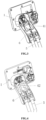
FIG. 1 is a structural schematic of a flexible connection structure of a connector of the present disclosure; -
FIG. 2 is a side view of a flexible connection structure of a connector of the present disclosure; -
FIG. 3 is a structural schematic of an aluminum flat belt of a flexible connection structure of a connector of the present disclosure; -
FIG. 4 is a structural schematic of a spiral conductor of a flexible connection structure of a connector of the present disclosure. - 1. connector body; 2. plug-in terminal; 3. first connecting member; 4. flexible conductor; 41. woven aluminum flat belt; 42. spiral conductor; 5. transmission conductor; 6. second connecting member.
- Various exemplary embodiments of the disclosure will now be described in detail with reference to the accompanying drawings. It should be noted that, unless otherwise specified, the relative arrangements, numerical expressions, and numerical values of parts and steps set forth in these embodiments do not limit the scope of the present disclosure.
- The following description of at least one exemplary embodiment is in fact illustrative only and in no way constitutes any limitation to the present disclosure, and its application or use.
- Technologies, methods and apparatuses known to those ordinarily skilled in the art may not be discussed in detail, but where appropriate, said technologies, methods and apparatuses shall be considered as part of the specification.
- In all the examples shown and discussed here, any specific value should be interpreted as merely exemplary and does not serve as limitation. Therefore, other examples of the exemplary embodiments may have different values.
- The disclosure discloses a flexible connection structure of a connector, as shown in
FIGs. 1 to 4 , - including a
connector body 1, a flexible conductor 4 and atransmission conductor 5, in which theconnector body 1 is provided therein with a plug-interminal 2, an end of the plug-interminal 2 is provided with a first connectingmember 3, and an end of thetransmission conductor 5 is provided with a second connectingmember 6; - one end of the flexible conductor 4 is electrically connected to the first connecting
member 3, and the other end of the flexible conductor is electrically connected to the second connectingmember 6. - The existing connector structure is that a
transmission conductor 5 is directly connected to a terminal in theconnector body 1. The whole connection structure makes the connector and the terminal be rigidly fixed, and phenomenon of terminal eccentric wear may occur during insertion and removal of the charging gun. The phenomenon of eccentric wear refers to the phenomenon that the repeated friction at the plug-in part between the terminal and an opposite plug end that occurs due to being stressed unevenly in all directions causes the plating layer to be damaged and to expose the terminal body. After the terminal body is exposed, the resistance increases, the current weakens, and heat generation amount increases, which affects the safety and charging efficiency of high-voltage charging for a long time. The flexible conductor 4 of the disclosure can not only conduct electricity but also has its own flexibility, so that the plug-in terminal 2 in theconnector body 1 can have a certain activity space. When the charging gun is inserted into theconnector body 1, due to the presence of the flexible conductor 4, theconnector terminal 2 may move slightly in the direction of the force at which the charging gun is inserted, so as to avoid the increase in friction strength caused by excessive stress on a certain surface caused by rigid contact. In addition, due to soft characteristics of the flexible conductor 4, it is not suitable for connection methods that facilitate detachment such as screw connection, and can only adopt fixed connection methods such as welding, so that it is not easy to separate the flexible conductor 4 from thetransmission conductor 5 for easy replacement. In this case, a second connectingmember 6 is provided to connect the flexible conductor 4 and thetransmission conductor 5, so as to facilitate detachment, that is, it is only necessary to separate the second connectingmember 6 from thetransmission conductor 5, when theconnector body 1 needs to be replaced. - Further, when the second connecting
member 6 vibrates, the flexible conductor 4 deforms so as to buffer the vibration of the second connectingmember 6. During driving of the vehicle, thetransmission conductor 5 may swing with the vehicle body, and long-time swing may drive the second connectingmember 6 to vibrate, and when the second connectingmember 6 vibrates, it may drive the plug-in terminal 2 to shake in rigid connection, and long-term shake may damage the connection structure of the plug-interminal 2 and theconnector body 1. Therefore, the flexible conductor 4 is disposed to prevent the vibration of the second connectingmember 6 from being transferred to the plug-inconnector 2 through its own deformation, thereby protecting the plug-interminal 2. - In some embodiments, The flexible conductor 4 is radially displaced along the length direction of the flexible conductor 4 at least 2% of the length of the flexible conductor 4 from one end connected to the second connecting
member 6, and along the length direction of the flexible conductor 4, the flexible conductor 4 is displaced in a portion of at least 2% of the length of the flexible conductor 4 is displaced in the direction of the length of the flexible conductor 4. If the radial displacement length of the flexible conductor 4 is too small, the buffer produced to the vibration is not enough to fully buffer the vibration of the second connectingmember 6. In order to find an appropriate ratio of the length at which the flexible conductor 4 is radially displaced to the length of the flexible conductor 4, the inventor conducted relevant tests. The test method is to select the same second connectingmember 6 and a different flexible conductor 4 to form a sample. The flexible conductor 4 has different lengths at which it can be radially displaced. The sample is subjected to vibration test for one hour. If the rate of increase in impedance being greater than 2% is regarded as being not qualified, it indicates that fretting corrosion still exists, and it is unqualified, and the results are shown in Table 1.Table 1: Influence of the ratio of the length at which the flexible conductor 4 is radially displaced to the length of the flexible conductor on the impedance The ratio of the length at which the flexible conductor 4 is radially displaced to the length of the flexible conductor (%) 1.8 1.9 2 2.1 2.2 2.4 2.6 3 3.2 3.5 Impedance rise rate (%) 2.5 2.2 2 1.9 1.8 1.7 1.7 1.5 1.5 1.4 - As shown in Table 1, when the ratio of the length at which the flexible conductor 4 is radially displaced to the length of the flexible conductor is less than 2%, the impedance between the flexible conductor 4 and the second connecting
member 6 after vibration test rises by more than 2%. Therefore, it is exemplary that the flexible conductor 4 begins at an end connected to the second connectingmember 6, and a portion that accounts for at least 2% of length of the flexible conductor 4 is radially displaced along the length direction of the flexible conductor 4. - Therefore, through testing, the inventor finds that if the vibrating part of the flexible conductor 4 is less than 2% of the total length of the flexible conductor 4, it cannot effectively buffer the vibration of the second connecting
member 6, and the force generated by the vibration is concentratedly released at the connection part of the flexible conductor 4 and the second connectingmember 6, and if this is done for a long time, the flexible conductor 4 and the second connectingmember 6 may be separated very easily, resulting in disconnection. Therefore, it is exemplary that a portion that accounts for at least 2% of length of the flexible conductor 4 is radially displaced. - In some embodiments, the flexible conductor 4 begins at an end connected to the first connecting
member 3, and a portion that accounts for at least 1% of length of the flexible conductor 4 is not radially displaced along the length direction of the flexible conductor 4. - If the portion of the flexible conductor 4 that is not radially displaced is too small, the vibration of the second connecting
member 6 may still be transferred to the first connectingmember 3. In order to find an appropriate ratio of the length at which the flexible conductor 4 is not radially displaced to the length of the flexible conductor 4, the inventor conducted relevant tests. The test method is to select the same first connectingmember 3 and a different flexible conductor 4 to form a sample. The flexible conductor 4 has different lengths at which it can be radially displaced. The sample is subjected to vibration test for one hour. If the rate of increase in impedance being greater than 2% is regarded as being not qualified, it indicates that fretting corrosion still exists, and it is unqualified, and the results are shown in Table 2.Table 2: Influence of the ratio of the length at which the flexible conductor 4 is not radially displaced to the length of the flexible conductor on the impedance The ratio of the length at which the flexible conductor 4 is radially displaced to the length of the flexible conductor (%) 0.8 0.9 1 1.1 1.2 1.4 1.6 1.8 2 2.2 Impedance rise rate (%) 2.5 2.2 2 1.9 1.8 1.8 1.6 1.5 1.5 1.4 - As shown in Table 2, when the ratio of the length at which the flexible conductor 4 is not radially displaced to the length of the flexible conductor is less than 1%, the impedance between the flexible conductor 4 and the first connecting
member 3 after the vibration test rises by more than 2%, it is regarded as being not qualified. Therefore, it is exemplary that the flexible conductor 4 begins at an end connected to the first connectingmember 3, and a portion that accounts for at least 1% of length of the flexible conductor 4 is not radially displaced along the length direction of the flexible conductor 4. - In some embodiments, the plug-in
terminal 2 and the first connectingmember 3 form an integrated structure. The integrated structure reduces the number of parts, facilitates processing, and can reduce processes and costs. - In some embodiments, the plug-in
terminal 2 and the first connectingmember 3 are separate structures, and the plug-interminal 2 and the first connectingmember 3 are fixedly connected by welding or crimping. The material of the plug-interminal 2 is generally copper or copper alloy, and the flexible conductor 4 may be aluminum. Copper or copper alloy have high electrical conductivity and can be widely used in the field of electrical transmission. The flexible conductor 4 is connected to the plug-interminal 2 by welding. The welding methods adopted include one or several of resistance welding, friction welding, ultrasonic welding, arc welding, laser welding, electron beam welding, pressure diffusion welding and magnetic induction welding. The concentrated heat energy or pressure is used to create a fused connection at a position of contact between the plug-interminal 2 and the flexible conductor 4, to produce stable connection by the welding. Such welding can achieve connection of dissimilar materials, and has better conductive effect due to contact position fusion. - The resistance welding refers to a method of welding by strong current passing through the contact point between the electrode and the workpiece to generate heat from the contact resistance.
- The friction welding refers to a method of welding by using the heat generated by the friction of the workpiece contact surface as the heat source to make the workpiece produce plastic deformation under the action of pressure.
- The ultrasonic welding refers to that high-frequency vibration wave is transmitted to the surfaces of two objects to be welded, and under pressurization, the surfaces of two objects rub against each other to form a fusion between molecular layers.
- The arc welding refers to that electric arc is taken as the heat source and the physical phenomenon of atmospherical discharges is utilized to convert electrical energy into thermal and mechanical energy required for welding, so as to achieve the purpose of connecting metal, and the main methods include welding electrode arc welding, submerged arc welding, gas shielded welding and so on.
- The laser welding method refers to an efficient and precise welding method using a laser beam with high energy density as a heat source.
- The friction welding method refers to a method of welding by using the heat generated by the friction of the workpiece contact surface as the heat source to make the workpiece produce plastic deformation under the action of pressure.
- The electron beam welding method refers to the use of accelerated and focused electron beam to bombard the welding surface placed in vacuum or non-vacuum, so that the welded workpiece is melted to achieve welding.
- The pressure welding method is a method of applying pressure to a weldment to make the binding surface be in contact closely to produce a certain plastic deformation and complete the welding.
- The magnetic induction welding refers to that instantaneous high-speed collision occurs between two workpieces to be welded under the action of strong pulsed magnetic field, and when surface of the material is subjected to high pressure waves, the atoms of the two materials meet in the interatomic distance, thus forming a stable metallurgical bond at the interface, which is a type of solid-state cold welding that can weld together conductive metals with similar or dissimilar properties.
- The crimping refers to the production process that after the plug-in
terminal 2 and the first connectingmember 3 are assembled, the two are stamped into one using a crimping machine. The advantage of crimping is mass production, and a large amount of products with stable quality can be produced quickly by using an automatic crimping machine. - In some embodiments, the plug-in
terminal 2 and the first connectingmember 3 are separate structures, and the plug-interminal 2 and the first connectingmember 3 are detachably connected by clamping or screw connection or riveting. The clamping refers to that corresponding clamping claw or clamping slot are arranged on the plug-interminal 2 and the first connectingmember 3 respectively, which are connected together by being assembled through the clamping slot or clamping claw. The clamping method has advantages of fast connection and detachability. - The screw connection refers to that the plug-in
terminal 2 and the first connectingmember 3 respectively have a threaded structure and can be screwed together with each other, or connected together using separate studs and nuts. The advantage of the threaded connection is detachability, and assembling and disassembling can be performed repeatedly, which is suitable for scenarios that require frequent disassembly. - Riveting refers to that the plug-in
terminal 2 and the first connectingmember 3 are riveted together by using rivets. The riveting has advantages of firm connection, simple processing method and easy operation. - In some embodiments, the
transmission conductor 5 and the second connectingmember 6 form an integrated structure. The integrated structure can reduce the number of parts, facilitates construction, and can reduce processes and costs. - In some embodiments, the
transmission conductor 5 and the second connectingmember 6 are fixedly connected by welding or crimping. - In some embodiments, the flexible conductor 4 is connected to the first connecting
member 3 by welding or crimping. - The welding methods adopted include one or several of resistance welding, friction welding, ultrasonic welding, arc welding, laser welding, electron beam welding, pressure diffusion welding and magnetic induction welding. Such welding can obtain stable connection, can achieve connection of dissimilar materials, and has better conductive effect due to contact position fusion. The specific welding method is as described above. The advantage of crimping is mass production, and a large amount of products with stable quality can be produced quickly by using an automatic crimping machine.
- In some embodiments, the
transmission conductor 5 and the second connectingmember 6 are detachably connected by clamping or screw connection or riveting. The clamping refers to that corresponding clamping claw or clamping slot are arranged on thetransmission conductor 5 and the second connectingmember 6 respectively, which are connected together by being assembled through the clamping slot or clamping claw. The clamping method has advantages of fast connection and detachability. - The screw connection refers to that the
transmission conductor 5 and the second connectingmember 6 respectively have a threaded structure and can be screwed together with each other, or connected together using separate studs and nuts. The advantage of the threaded connection is detachability, and assembling and disassembling can be performed repeatedly, which is suitable for scenarios that require frequent disassembly. - Riveting refers to that the
transmission conductor 5 and the second connectingmember 6 are riveted together by using rivets. The riveting has advantages of firm connection, simple processing method and easy operation. - In some embodiments, the flexible conductor 4 is a woven aluminum
flat belt 41. As shown inFIG. 3 , the woven aluminumflat belt 41 is flexible, easy to bend and has excellent electrical conductivity. - In some embodiments, the flexible conductor 4 is a flexible flat belt formed by stacking multiple layers of thin plates. The thin plates are made of soft material and easy to deform, suitable for being used as the flexible conductor 4, and stacking of multiple layers of thin plates can not only ensure flexibility, but also ensure the efficiency of electrification.
- Further, the flexible conductor 4 has a twisted portion, and an angle between two adjacent planes connected by the twisted portion is 0° to 90°. An outlet angle of the
transmission conductor 5 may differ indifferent connector bodies 1, and the flexible conductor 4 can be set to have a twisted portion, that is, two ends of the flexible conductor 4 form a certain angle by twisting of the twisted portion, the angle can be any value according to the need, so as to meet different assembly environments. - In some embodiments, the flexible conductor 4 is formed by winding or stranding multi-core wires. The multi-core wire is flexible, easy to bend and has excellent electrical conductivity. The two ends of the flexible conductor 4 made of the multi-core wire can be provided with planes for welding in different directions according to the needs. Because the flexible conductor 4 conducts a high current, large electromagnetic interference is generated in the surrounding area. In order to avoid the impact of electromagnetic interference on the electric devices of the vehicle, the flexible conductor 4 can be made by winding or stranding unshielded multi-core wires one another to reduce the electromagnetic interference generated by the flexible conductor 4. The electromagnetic interference generated by the mutually stranded flexible conductors 4 may be offset by each other, so as to no longer affect the electrical devices of the vehicle, reduce the use of shielding layers, reduce processing and material costs, and reduce the cost of the vehicle.
- In some other embodiments, the flexible conductor 4 is a
spiral conductor 42. As shown inFIG. 4 , thespiral conductor 42 is spring-like and has elasticity of a spring, which can release the vibration force well. - In some embodiments, the flexible conductor 4 has a different cross-sectional area from the first connecting
member 3 or the second connectingmember 6. During transmission of current, the cross-sectional area only needs to meet the current transmission needs, so that the cross-sectional area can be reduced while sufficient current strength can still be ensured, thereby saving costs. - In some other embodiments, the flexible conductor 4 has a different cross-section shape from the first connecting
member 3 or the second connectingmember 6. In this way, the flexible conductor 4 can be arranged in different connectors according to the needs, so as to meet different assembly environments, and conveniently extend into the connectors with different apertures. - In some embodiments, the flexible conductor 4 and the first connecting
member 3 are detachably connected by clamping or screw connection or riveting. The clamping refers to that corresponding clamping claw or clamping slot are arranged on the flexible conductor 4 and the first connectingmember 3 respectively, which are connected together by being assembled through the clamping slot or clamping claw. The clamping method has advantages of fast connection and detachability. - The screw connection refers to that the flexible conductor 4 and the first connecting
member 3 respectively have a threaded structure and can be screwed together with each other, or connected together using separate studs and nuts. The advantage of the threaded connection is detachability, and assembling and disassembling can be performed repeatedly, which is suitable for scenarios that require frequent disassembly. - Riveting refers to that the flexible conductor 4 and the first connecting
member 3 are riveted together by using rivets. The riveting has advantages of firm connection, simple processing method and easy operation. - In some embodiments, an end of the first connecting
member 3 is a first flat portion, the first flat portion has a first through hole, the flexible conductor 4 has a second through hole, and the first through hole and the second through hole are connected through a bolt or rivet. The first flat portion and the flexible conductor 4 are more suitable for screw connection or riveting, and are firmer than cylindrical direct screw connection. - Further, the number of the first flat portion is two, the two first flat portions are in parallel and both have a first through hole, and the second through hole is between the two first through holes. That is to say, two first flat portions clamp the flexible conductor 4 in the middle, and the second through hole is arranged between the two first through holes and then fixed with bolts to make the connection firmer.
- In some embodiments, the flexible conductor 4 and the second connecting
member 6 are detachably connected by clamping or screw connection or riveting. The clamping refers to that corresponding clamping claw or clamping slot are arranged on the flexible conductor 4 and the second connectingmember 6 respectively, which are connected together by being assembled through the clamping slot or clamping claw. The clamping method has advantages of fast connection and detachability. - The screw connection refers to that the flexible conductor 4 and the second connecting
member 6 respectively have a threaded structure and can be screwed together with each other, or connected together using separate studs and nuts. The advantage of the threaded connection is detachability, and assembling and disassembling can be performed repeatedly, which is suitable for scenarios that require frequent disassembly. - Riveting refers to that the flexible conductor 4 and the second connecting
member 6 are riveted together by using rivets. The riveting has advantages of firm connection, simple processing method and easy operation. - In some embodiments, an end of the second connecting member is a second flat portion, the second flat portion has a third through hole, the flexible conductor has a fourth through hole, and the third through hole and the fourth through hole are connected through a bolt or rivet.
- Further, the number of the second flat portion is two, the two second flat portions are in parallel and both have a third through hole, and the fourth through hole is between the two third through holes. That is to say, two first flat portions clamp the flexible conductor 4 in the middle, and the second through hole is arranged between the two first through holes and then fixed with bolts to make the connection firmer.
- In some embodiments, the material of the plug-in terminal 2 contains copper. The plug-in
connector 2 containing copper material has high electrical conductivity and can effectively improve the charging efficiency as part of the charging system. - In some embodiments, the material of the
transmission conductor 5 and/or the flexible conductor 4 contains aluminum. The electrical conductivity of aluminum is second only to copper, and aluminum resource storage is large and cheap, and becomes one of the main materials to replace copper cables. Moreover, the weight of aluminum is light, and thetransmission conductor 5 and the flexible conductor 4 made of material containing aluminum can effectively reduce the weight of the vehicle body. - In some embodiments, the
connector body 1 is a charging socket body. The plug-interminal 2 is arranged in the charging socket body. The first connectingmember 3, the flexible conductor 4, the second connectingmember 6 and thetransmission conductor 5 are connected successively on the plug-interminal 2. Thetransmission conductor 5 is connected with the vehicle-mounted battery to form the charging system of the electric vehicle. - The disclosure further discloses a vehicle including a flexible connection structure of a connector described above, and the
connector body 1 is detachably arranged on the vehicle. - Although some specific embodiments of the disclosure have been described in detail by examples, it should be understood by those skilled in the art that the above examples are intended only for illustration and not to limit the scope of the disclosure. Those skilled in the art should understand that the above embodiments may be modified without departing from the spirit or scope of the disclosure. The scope of the disclosure is limited by the appended claims.
Claims (28)
- A flexible connection structure of a connector, wherein comprising a connector body, a flexible conductor and a transmission conductor, the connector body is provided therein with a plug-in terminal, an end of the plug-in terminal is provided with a first connecting member, and an end of the transmission conductor is provided with a second connecting member;
one end of the flexible conductor is electrically connected to the first connecting member, and the other end of the flexible conductor is electrically connected to the second connecting member. - The flexible connection structure of a connector according to claim 1, wherein, when the second connecting member vibrates, the flexible conductor deforms so as to buffer the vibration of the second connecting member.
- The flexible connection structure of a connector according to claim 2, wherein the flexible conductor begins at an end connected to the second connecting member, and a portion that accounts for at least 2% of length of the flexible conductor is radially displaced along the length direction of the flexible conductor.
- The flexible connection structure of a connector according to claim 2, wherein the flexible conductor begins at an end connected to the first connecting member, and a portion that accounts for at least 1% of length of the flexible conductor is not radially displaced along the length direction of the flexible conductor.
- The flexible connection structure of a connector according to claim 1, wherein the plug-in terminal and the first connecting member form an integrated structure.
- The flexible connection structure of a connector according to claim 1, wherein the plug-in terminal and the first connecting member are separate structures, and the plug-in terminal and the first connecting member are fixedly connected by welding or crimping.
- The flexible connection structure of a connector according to claim 1, wherein the plug-in terminal and the first connecting member are separate structures, and the plug-in terminal and the first connecting member are detachably connected by clamping or screw connection or riveting.
- The flexible connection structure of a connector according to claim 1, wherein the transmission conductor and the second connecting member form an integrated structure.
- The flexible connection structure of a connector according to claim 1, wherein the transmission conductor and the second connecting member are fixedly connected by welding or crimping.
- The flexible connection structure of a connector according to claim 1, wherein the transmission conductor and the second connecting member are detachably connected by clamping or screw connection or riveting.
- The flexible connection structure of a connector according to claim 1, wherein the flexible conductor is a woven flat belt.
- The flexible connection structure of a connector according to claim 1, wherein the flexible conductor is a flexible flat belt formed by stacking multiple layers of thin plates.
- The flexible connection structure of a connector according to any of claim 11 or 12, wherein the flexible conductor has a twisted portion, and an angle between two adjacent planes connected by the twisted portion is 0° to 90°.
- The flexible connection structure of a connector according to claim 1, wherein the flexible conductor is formed by winding or stranding multi-core wires.
- The flexible connection structure of a connector according to claim 1, wherein the flexible conductor is a spiral conductor.
- The flexible connection structure of a connector according to claim 1, wherein the flexible conductor has a different cross-sectional area from the first connecting member or the second connecting member.
- The flexible connection structure of a connector according to claim 1, wherein the flexible conductor has a different cross-section shape from the first connecting member or the second connecting member.
- The flexible connection structure of a connector according to claim 1, wherein the flexible conductor is connected to the first connecting member by welding or crimping.
- The flexible connection structure of a connector according to claim 1, wherein the flexible conductor and the first connecting member are detachably connected by clamping or screw connection or riveting.
- The flexible connection structure of a connector according to claim 19, wherein an end of the first connecting member is a first flat portion, the first flat portion has a first through hole, the flexible conductor has a second through hole, and the first through hole and the second through hole are connected through a bolt or rivet.
- The flexible connection structure of a connector according to claim 20, wherein the number of the first flat portion is two, the two first flat portions are in parallel and both have a first through hole, and the second through hole is between the two first through holes.
- The flexible connection structure of a connector according to claim 1, wherein the flexible conductor and the second connecting member are detachably connected by clamping or screw connection or riveting.
- The flexible connection structure of a connector according to claim 22, wherein an end of the second connecting member is a second flat portion, the second flat portion has a third through hole, the flexible conductor has a fourth through hole, and the third through hole and the fourth through hole are connected through a bolt or rivet.
- The flexible connection structure of a connector according to claim 23, wherein the number of the second flat portion is two, the two second flat portions are in parallel and both have a third through hole, and the fourth through hole is between the two third through holes.
- The flexible connection structure of a connector according to claim 1, wherein the material of the plug-in terminal contains copper.
- The flexible connection structure of a connector according to claim 1, wherein the material of the transmission conductor and/or the flexible conductor contains aluminum.
- The flexible connection structure of a connector according to claim 1, wherein the connector body is a charging socket body.
- A vehicle, wherein comprising a flexible connection structure of a connector according to any of claims 1 to 27, and the connector body is detachably arranged on the vehicle.
Applications Claiming Priority (2)
| Application Number | Priority Date | Filing Date | Title |
|---|---|---|---|
| CN202210248399.XA CN114709667A (en) | 2022-03-14 | 2022-03-14 | Connector flexible connection structure and vehicle |
| PCT/CN2023/081403 WO2023174290A1 (en) | 2022-03-14 | 2023-03-14 | Flexible connecting structure of connector and vehicle |
Publications (2)
| Publication Number | Publication Date |
|---|---|
| EP4494918A1 true EP4494918A1 (en) | 2025-01-22 |
| EP4494918A4 EP4494918A4 (en) | 2025-07-09 |
Family
ID=82169308
Family Applications (1)
| Application Number | Title | Priority Date | Filing Date |
|---|---|---|---|
| EP23769792.5A Pending EP4494918A4 (en) | 2022-03-14 | 2023-03-14 | FLEXIBLE CONNECTION STRUCTURE OF A CONNECTOR AND VEHICLE |
Country Status (6)
| Country | Link |
|---|---|
| US (1) | US20250222794A1 (en) |
| EP (1) | EP4494918A4 (en) |
| JP (1) | JP2025508186A (en) |
| CN (1) | CN114709667A (en) |
| MX (1) | MX2024011208A (en) |
| WO (1) | WO2023174290A1 (en) |
Families Citing this family (1)
| Publication number | Priority date | Publication date | Assignee | Title |
|---|---|---|---|---|
| CN114709667A (en) * | 2022-03-14 | 2022-07-05 | 吉林省中赢高科技有限公司 | Connector flexible connection structure and vehicle |
Family Cites Families (29)
| Publication number | Priority date | Publication date | Assignee | Title |
|---|---|---|---|---|
| JP2008041331A (en) * | 2006-08-02 | 2008-02-21 | Sumiden Asahi Industries Ltd | Vehicular flexible bus bar |
| EP2441103B2 (en) * | 2009-06-08 | 2018-09-12 | Auto-Kabel Management GmbH | Battery cell connector |
| JP5904786B2 (en) * | 2011-12-28 | 2016-04-20 | 矢崎総業株式会社 | Coil unit and non-contact power feeding device |
| JP2014011134A (en) * | 2012-07-03 | 2014-01-20 | Auto Network Gijutsu Kenkyusho:Kk | connector |
| JP2014053091A (en) * | 2012-09-05 | 2014-03-20 | Japan Aviation Electronics Industry Ltd | Power incoming side connector for charging electric vehicle |
| JP5776665B2 (en) * | 2012-10-19 | 2015-09-09 | 株式会社オートネットワーク技術研究所 | Shield connector |
| JP2014194860A (en) * | 2013-03-28 | 2014-10-09 | Sumitomo Wiring Syst Ltd | Electric wire, connection structure of electric wire, and joint connector |
| EP3050162B1 (en) * | 2013-09-25 | 2018-10-24 | TE Connectivity Corporation | Electrical system |
| TWI622328B (en) * | 2014-03-03 | 2018-04-21 | Stretchable flexible circuit board | |
| JP6132868B2 (en) * | 2015-03-31 | 2017-05-24 | 矢崎総業株式会社 | connector |
| DE102016001572A1 (en) * | 2016-02-11 | 2017-08-17 | Sumitomo Wiring Systems, Ltd. | Charging connector, terminal fitting and method for fixing a sensor to a terminal fitting |
| DE102016105470A1 (en) * | 2016-03-23 | 2017-09-28 | Te Connectivity Germany Gmbh | Power electrical contact device; replaceable, power-electric contact module and power-electrical connector |
| DE102017105682A1 (en) * | 2017-03-16 | 2018-09-20 | Te Connectivity Germany Gmbh | Contact carrier, electrical contact device and method for producing a ready-made cable |
| CN107819223A (en) * | 2017-11-10 | 2018-03-20 | 深圳巴斯巴科技发展有限公司 | A kind of connection terminal of energy rapid-maintenance |
| DE102018100831A1 (en) * | 2018-01-16 | 2019-07-18 | Dr. Ing. H.C. F. Porsche Aktiengesellschaft | Charging plug for electric cars and its manufacture |
| CN207883942U (en) * | 2018-02-11 | 2018-09-18 | 四川永贵科技有限公司 | A kind of flexible wiring construction for connector |
| JP2019186110A (en) * | 2018-04-13 | 2019-10-24 | 矢崎総業株式会社 | Terminal-equipped electrical wire |
| JP7290312B2 (en) * | 2018-07-03 | 2023-06-13 | 株式会社アイエイアイ | Actuator and SCARA robot |
| CN209014621U (en) * | 2018-11-02 | 2019-06-21 | 国网河南省电力公司汝阳县供电公司 | A kind of new-type cable identifier |
| CN219535102U (en) * | 2019-09-02 | 2023-08-15 | 东莞市源创电子科技有限公司 | Data line |
| JP7017591B2 (en) * | 2020-02-04 | 2022-02-08 | 矢崎総業株式会社 | Wire with terminal and sensor fixing method |
| JP7074789B2 (en) * | 2020-03-16 | 2022-05-24 | 矢崎総業株式会社 | connector |
| JP7104100B2 (en) * | 2020-06-22 | 2022-07-20 | 矢崎総業株式会社 | connector |
| CN214477973U (en) * | 2021-03-04 | 2021-10-22 | 深圳市沃尔核材股份有限公司 | Tubular busbar connection structure |
| CN215184555U (en) * | 2021-05-31 | 2021-12-14 | 深圳市沃尔新能源电气科技股份有限公司 | Connecting terminal, charging seat and electric automobile |
| CN215732301U (en) * | 2021-08-17 | 2022-02-01 | 长春捷翼汽车零部件有限公司 | Micro-vibration terminal, plug structure and motor vehicle |
| CN113708172A (en) * | 2021-08-26 | 2021-11-26 | 长春捷翼汽车零部件有限公司 | Electric energy transmission changeover mechanism, charging socket and motor vehicle |
| CN217823495U (en) * | 2022-03-14 | 2022-11-15 | 吉林省中赢高科技有限公司 | Connector flexible connection structure and vehicle |
| CN114709667A (en) * | 2022-03-14 | 2022-07-05 | 吉林省中赢高科技有限公司 | Connector flexible connection structure and vehicle |
-
2022
- 2022-03-14 CN CN202210248399.XA patent/CN114709667A/en active Pending
-
2023
- 2023-03-14 JP JP2024554854A patent/JP2025508186A/en active Pending
- 2023-03-14 US US18/847,566 patent/US20250222794A1/en active Pending
- 2023-03-14 EP EP23769792.5A patent/EP4494918A4/en active Pending
- 2023-03-14 WO PCT/CN2023/081403 patent/WO2023174290A1/en not_active Ceased
-
2024
- 2024-09-12 MX MX2024011208A patent/MX2024011208A/en unknown
Also Published As
| Publication number | Publication date |
|---|---|
| MX2024011208A (en) | 2024-11-08 |
| WO2023174290A1 (en) | 2023-09-21 |
| EP4494918A4 (en) | 2025-07-09 |
| JP2025508186A (en) | 2025-03-21 |
| US20250222794A1 (en) | 2025-07-10 |
| CN114709667A (en) | 2022-07-05 |
Similar Documents
| Publication | Publication Date | Title |
|---|---|---|
| EP4395086B1 (en) | Transfer mechanism for power transmission, charging socket, and motor vehicle | |
| US20240391333A1 (en) | Electric energy transmission system for vehicle, and charging apparatus and electric vehicle | |
| US20250192458A1 (en) | Electric energy transmission assembly and vehicle | |
| EP4459814A1 (en) | Conveniently replaceable charging socket and vehicle | |
| EP4496153A1 (en) | Electric energy transmission assembly and vehicle | |
| CN216251492U (en) | A power transmission and transfer mechanism, charging socket and motor vehicle | |
| US20250196673A1 (en) | Electric energy transmission connecting device and vehicle | |
| CN218569243U (en) | Novel aluminum terminal | |
| CN217823578U (en) | Buffering location structure and vehicle of connector pencil | |
| US20250222794A1 (en) | Flexible connecting structure of connector and vehicle | |
| US20250192493A1 (en) | Multi-core electric connector assembly and vehicle | |
| US20250201440A1 (en) | Electric energy transmission assembly and vehicle | |
| EP4496144A1 (en) | Connector assembly and processing method | |
| CN217823495U (en) | Connector flexible connection structure and vehicle | |
| CN217823621U (en) | Connector assembly and vehicle | |
| CN215944316U (en) | Electric energy transmission system for vehicle, charging device and electric vehicle | |
| CN217823616U (en) | Multicore electric connector assembly and vehicle | |
| EP4496143A1 (en) | Connector assembly and vehicle | |
| CN217215265U (en) | Cable sealing structure capable of releasing stress and vehicle | |
| EP4379971B1 (en) | Wiring harness module and combined wiring harness | |
| US20250192497A1 (en) | Novel shielding material based connector assembly, and vehicle | |
| CN218569255U (en) | Electric connector and electric connection structure | |
| EP4131671B1 (en) | Profiled connector | |
| CN217215308U (en) | Novel electronic lock and charging seat |
Legal Events
| Date | Code | Title | Description |
|---|---|---|---|
| STAA | Information on the status of an ep patent application or granted ep patent |
Free format text: STATUS: THE INTERNATIONAL PUBLICATION HAS BEEN MADE |
|
| PUAI | Public reference made under article 153(3) epc to a published international application that has entered the european phase |
Free format text: ORIGINAL CODE: 0009012 |
|
| STAA | Information on the status of an ep patent application or granted ep patent |
Free format text: STATUS: REQUEST FOR EXAMINATION WAS MADE |
|
| 17P | Request for examination filed |
Effective date: 20241011 |
|
| AK | Designated contracting states |
Kind code of ref document: A1 Designated state(s): AL AT BE BG CH CY CZ DE DK EE ES FI FR GB GR HR HU IE IS IT LI LT LU LV MC ME MK MT NL NO PL PT RO RS SE SI SK SM TR |
|
| DAV | Request for validation of the european patent (deleted) | ||
| DAX | Request for extension of the european patent (deleted) | ||
| P01 | Opt-out of the competence of the unified patent court (upc) registered |
Free format text: CASE NUMBER: APP_22620/2025 Effective date: 20250513 |
|
| A4 | Supplementary search report drawn up and despatched |
Effective date: 20250610 |
|
| RIC1 | Information provided on ipc code assigned before grant |
Ipc: H01R 11/01 20060101ALI20250603BHEP Ipc: B60L 53/18 20190101ALI20250603BHEP Ipc: B60L 3/00 20190101ALI20250603BHEP Ipc: H01R 13/58 20060101ALI20250603BHEP Ipc: H01R 13/629 20060101ALI20250603BHEP Ipc: H01R 13/631 20060101ALI20250603BHEP Ipc: B60L 53/16 20190101AFI20250603BHEP |
|
| GRAP | Despatch of communication of intention to grant a patent |
Free format text: ORIGINAL CODE: EPIDOSNIGR1 |
|
| STAA | Information on the status of an ep patent application or granted ep patent |
Free format text: STATUS: GRANT OF PATENT IS INTENDED |
|
| INTG | Intention to grant announced |
Effective date: 20260223 |
|
| GRAS | Grant fee paid |
Free format text: ORIGINAL CODE: EPIDOSNIGR3 |
|
| GRAA | (expected) grant |
Free format text: ORIGINAL CODE: 0009210 |
|
| STAA | Information on the status of an ep patent application or granted ep patent |
Free format text: STATUS: THE PATENT HAS BEEN GRANTED |