EP4494911A1 - A method for increasing corner stability of a vehicle and electronic control module - Google Patents
A method for increasing corner stability of a vehicle and electronic control module Download PDFInfo
- Publication number
- EP4494911A1 EP4494911A1 EP23187037.9A EP23187037A EP4494911A1 EP 4494911 A1 EP4494911 A1 EP 4494911A1 EP 23187037 A EP23187037 A EP 23187037A EP 4494911 A1 EP4494911 A1 EP 4494911A1
- Authority
- EP
- European Patent Office
- Prior art keywords
- vehicle
- lateral acceleration
- threshold
- expected
- reaction
- Prior art date
- Legal status (The legal status is an assumption and is not a legal conclusion. Google has not performed a legal analysis and makes no representation as to the accuracy of the status listed.)
- Granted
Links
Images
Classifications
-
- B—PERFORMING OPERATIONS; TRANSPORTING
- B60—VEHICLES IN GENERAL
- B60W—CONJOINT CONTROL OF VEHICLE SUB-UNITS OF DIFFERENT TYPE OR DIFFERENT FUNCTION; CONTROL SYSTEMS SPECIALLY ADAPTED FOR HYBRID VEHICLES; ROAD VEHICLE DRIVE CONTROL SYSTEMS FOR PURPOSES NOT RELATED TO THE CONTROL OF A PARTICULAR SUB-UNIT
- B60W30/00—Purposes of road vehicle drive control systems not related to the control of a particular sub-unit, e.g. of systems using conjoint control of vehicle sub-units
- B60W30/02—Control of vehicle driving stability
-
- B—PERFORMING OPERATIONS; TRANSPORTING
- B60—VEHICLES IN GENERAL
- B60K—ARRANGEMENT OR MOUNTING OF PROPULSION UNITS OR OF TRANSMISSIONS IN VEHICLES; ARRANGEMENT OR MOUNTING OF PLURAL DIVERSE PRIME-MOVERS IN VEHICLES; AUXILIARY DRIVES FOR VEHICLES; INSTRUMENTATION OR DASHBOARDS FOR VEHICLES; ARRANGEMENTS IN CONNECTION WITH COOLING, AIR INTAKE, GAS EXHAUST OR FUEL SUPPLY OF PROPULSION UNITS IN VEHICLES
- B60K31/00—Vehicle fittings, acting on a single sub-unit only, for automatically controlling vehicle speed, i.e. preventing speed from exceeding an arbitrarily established velocity or maintaining speed at a particular velocity, as selected by the vehicle operator
- B60K31/0066—Vehicle fittings, acting on a single sub-unit only, for automatically controlling vehicle speed, i.e. preventing speed from exceeding an arbitrarily established velocity or maintaining speed at a particular velocity, as selected by the vehicle operator responsive to vehicle path curvature
-
- B—PERFORMING OPERATIONS; TRANSPORTING
- B60—VEHICLES IN GENERAL
- B60K—ARRANGEMENT OR MOUNTING OF PROPULSION UNITS OR OF TRANSMISSIONS IN VEHICLES; ARRANGEMENT OR MOUNTING OF PLURAL DIVERSE PRIME-MOVERS IN VEHICLES; AUXILIARY DRIVES FOR VEHICLES; INSTRUMENTATION OR DASHBOARDS FOR VEHICLES; ARRANGEMENTS IN CONNECTION WITH COOLING, AIR INTAKE, GAS EXHAUST OR FUEL SUPPLY OF PROPULSION UNITS IN VEHICLES
- B60K31/00—Vehicle fittings, acting on a single sub-unit only, for automatically controlling vehicle speed, i.e. preventing speed from exceeding an arbitrarily established velocity or maintaining speed at a particular velocity, as selected by the vehicle operator
- B60K31/12—Vehicle fittings, acting on a single sub-unit only, for automatically controlling vehicle speed, i.e. preventing speed from exceeding an arbitrarily established velocity or maintaining speed at a particular velocity, as selected by the vehicle operator including a device responsive to centrifugal force
-
- B—PERFORMING OPERATIONS; TRANSPORTING
- B60—VEHICLES IN GENERAL
- B60W—CONJOINT CONTROL OF VEHICLE SUB-UNITS OF DIFFERENT TYPE OR DIFFERENT FUNCTION; CONTROL SYSTEMS SPECIALLY ADAPTED FOR HYBRID VEHICLES; ROAD VEHICLE DRIVE CONTROL SYSTEMS FOR PURPOSES NOT RELATED TO THE CONTROL OF A PARTICULAR SUB-UNIT
- B60W30/00—Purposes of road vehicle drive control systems not related to the control of a particular sub-unit, e.g. of systems using conjoint control of vehicle sub-units
- B60W30/18—Propelling the vehicle
- B60W30/18009—Propelling the vehicle related to particular drive situations
- B60W30/18109—Braking
- B60W30/18136—Engine braking
-
- B—PERFORMING OPERATIONS; TRANSPORTING
- B60—VEHICLES IN GENERAL
- B60W—CONJOINT CONTROL OF VEHICLE SUB-UNITS OF DIFFERENT TYPE OR DIFFERENT FUNCTION; CONTROL SYSTEMS SPECIALLY ADAPTED FOR HYBRID VEHICLES; ROAD VEHICLE DRIVE CONTROL SYSTEMS FOR PURPOSES NOT RELATED TO THE CONTROL OF A PARTICULAR SUB-UNIT
- B60W30/00—Purposes of road vehicle drive control systems not related to the control of a particular sub-unit, e.g. of systems using conjoint control of vehicle sub-units
- B60W30/18—Propelling the vehicle
- B60W30/18009—Propelling the vehicle related to particular drive situations
- B60W30/18145—Cornering
-
- B—PERFORMING OPERATIONS; TRANSPORTING
- B60—VEHICLES IN GENERAL
- B60W—CONJOINT CONTROL OF VEHICLE SUB-UNITS OF DIFFERENT TYPE OR DIFFERENT FUNCTION; CONTROL SYSTEMS SPECIALLY ADAPTED FOR HYBRID VEHICLES; ROAD VEHICLE DRIVE CONTROL SYSTEMS FOR PURPOSES NOT RELATED TO THE CONTROL OF A PARTICULAR SUB-UNIT
- B60W40/00—Estimation or calculation of non-directly measurable driving parameters for road vehicle drive control systems not related to the control of a particular sub unit, e.g. by using mathematical models
- B60W40/10—Estimation or calculation of non-directly measurable driving parameters for road vehicle drive control systems not related to the control of a particular sub unit, e.g. by using mathematical models related to vehicle motion
- B60W40/109—Lateral acceleration
-
- B—PERFORMING OPERATIONS; TRANSPORTING
- B60—VEHICLES IN GENERAL
- B60W—CONJOINT CONTROL OF VEHICLE SUB-UNITS OF DIFFERENT TYPE OR DIFFERENT FUNCTION; CONTROL SYSTEMS SPECIALLY ADAPTED FOR HYBRID VEHICLES; ROAD VEHICLE DRIVE CONTROL SYSTEMS FOR PURPOSES NOT RELATED TO THE CONTROL OF A PARTICULAR SUB-UNIT
- B60W50/00—Details of control systems for road vehicle drive control not related to the control of a particular sub-unit, e.g. process diagnostic or vehicle driver interfaces
- B60W50/0097—Predicting future conditions
-
- B—PERFORMING OPERATIONS; TRANSPORTING
- B60—VEHICLES IN GENERAL
- B60W—CONJOINT CONTROL OF VEHICLE SUB-UNITS OF DIFFERENT TYPE OR DIFFERENT FUNCTION; CONTROL SYSTEMS SPECIALLY ADAPTED FOR HYBRID VEHICLES; ROAD VEHICLE DRIVE CONTROL SYSTEMS FOR PURPOSES NOT RELATED TO THE CONTROL OF A PARTICULAR SUB-UNIT
- B60W50/00—Details of control systems for road vehicle drive control not related to the control of a particular sub-unit, e.g. process diagnostic or vehicle driver interfaces
- B60W50/08—Interaction between the driver and the control system
- B60W50/14—Means for informing the driver, warning the driver or prompting a driver intervention
-
- B—PERFORMING OPERATIONS; TRANSPORTING
- B60—VEHICLES IN GENERAL
- B60W—CONJOINT CONTROL OF VEHICLE SUB-UNITS OF DIFFERENT TYPE OR DIFFERENT FUNCTION; CONTROL SYSTEMS SPECIALLY ADAPTED FOR HYBRID VEHICLES; ROAD VEHICLE DRIVE CONTROL SYSTEMS FOR PURPOSES NOT RELATED TO THE CONTROL OF A PARTICULAR SUB-UNIT
- B60W2300/00—Indexing codes relating to the type of vehicle
- B60W2300/14—Tractor-trailers, i.e. combinations of a towing vehicle and one or more towed vehicles, e.g. caravans; Road trains
-
- B—PERFORMING OPERATIONS; TRANSPORTING
- B60—VEHICLES IN GENERAL
- B60W—CONJOINT CONTROL OF VEHICLE SUB-UNITS OF DIFFERENT TYPE OR DIFFERENT FUNCTION; CONTROL SYSTEMS SPECIALLY ADAPTED FOR HYBRID VEHICLES; ROAD VEHICLE DRIVE CONTROL SYSTEMS FOR PURPOSES NOT RELATED TO THE CONTROL OF A PARTICULAR SUB-UNIT
- B60W2520/00—Input parameters relating to overall vehicle dynamics
- B60W2520/10—Longitudinal speed
-
- B—PERFORMING OPERATIONS; TRANSPORTING
- B60—VEHICLES IN GENERAL
- B60W—CONJOINT CONTROL OF VEHICLE SUB-UNITS OF DIFFERENT TYPE OR DIFFERENT FUNCTION; CONTROL SYSTEMS SPECIALLY ADAPTED FOR HYBRID VEHICLES; ROAD VEHICLE DRIVE CONTROL SYSTEMS FOR PURPOSES NOT RELATED TO THE CONTROL OF A PARTICULAR SUB-UNIT
- B60W2520/00—Input parameters relating to overall vehicle dynamics
- B60W2520/12—Lateral speed
- B60W2520/125—Lateral acceleration
-
- B—PERFORMING OPERATIONS; TRANSPORTING
- B60—VEHICLES IN GENERAL
- B60W—CONJOINT CONTROL OF VEHICLE SUB-UNITS OF DIFFERENT TYPE OR DIFFERENT FUNCTION; CONTROL SYSTEMS SPECIALLY ADAPTED FOR HYBRID VEHICLES; ROAD VEHICLE DRIVE CONTROL SYSTEMS FOR PURPOSES NOT RELATED TO THE CONTROL OF A PARTICULAR SUB-UNIT
- B60W2530/00—Input parameters relating to vehicle conditions or values, not covered by groups B60W2510/00 or B60W2520/00
- B60W2530/203—Presence of trailer
-
- B—PERFORMING OPERATIONS; TRANSPORTING
- B60—VEHICLES IN GENERAL
- B60W—CONJOINT CONTROL OF VEHICLE SUB-UNITS OF DIFFERENT TYPE OR DIFFERENT FUNCTION; CONTROL SYSTEMS SPECIALLY ADAPTED FOR HYBRID VEHICLES; ROAD VEHICLE DRIVE CONTROL SYSTEMS FOR PURPOSES NOT RELATED TO THE CONTROL OF A PARTICULAR SUB-UNIT
- B60W2552/00—Input parameters relating to infrastructure
- B60W2552/30—Road curve radius
-
- B—PERFORMING OPERATIONS; TRANSPORTING
- B60—VEHICLES IN GENERAL
- B60W—CONJOINT CONTROL OF VEHICLE SUB-UNITS OF DIFFERENT TYPE OR DIFFERENT FUNCTION; CONTROL SYSTEMS SPECIALLY ADAPTED FOR HYBRID VEHICLES; ROAD VEHICLE DRIVE CONTROL SYSTEMS FOR PURPOSES NOT RELATED TO THE CONTROL OF A PARTICULAR SUB-UNIT
- B60W2710/00—Output or target parameters relating to a particular sub-units
- B60W2710/06—Combustion engines, Gas turbines
- B60W2710/0666—Engine torque
-
- B—PERFORMING OPERATIONS; TRANSPORTING
- B60—VEHICLES IN GENERAL
- B60W—CONJOINT CONTROL OF VEHICLE SUB-UNITS OF DIFFERENT TYPE OR DIFFERENT FUNCTION; CONTROL SYSTEMS SPECIALLY ADAPTED FOR HYBRID VEHICLES; ROAD VEHICLE DRIVE CONTROL SYSTEMS FOR PURPOSES NOT RELATED TO THE CONTROL OF A PARTICULAR SUB-UNIT
- B60W2710/00—Output or target parameters relating to a particular sub-units
- B60W2710/18—Braking system
-
- B—PERFORMING OPERATIONS; TRANSPORTING
- B60—VEHICLES IN GENERAL
- B60W—CONJOINT CONTROL OF VEHICLE SUB-UNITS OF DIFFERENT TYPE OR DIFFERENT FUNCTION; CONTROL SYSTEMS SPECIALLY ADAPTED FOR HYBRID VEHICLES; ROAD VEHICLE DRIVE CONTROL SYSTEMS FOR PURPOSES NOT RELATED TO THE CONTROL OF A PARTICULAR SUB-UNIT
- B60W2720/00—Output or target parameters relating to overall vehicle dynamics
- B60W2720/10—Longitudinal speed
Definitions
- the invention relates to a method for increasing corner stability of a vehicle and to a corresponding control module.
- Vehicles typically drive on roads, which can comprise curves.
- a vehicle In a curve, a vehicle is subject to a lateral acceleration, which may lead to understeering or oversteering.
- electronic stability control systems can be used in vehicles in order to reduce understeering or oversteering by selectively applying a brake force to one wheel of an axis.
- the invention relates to a method for increasing corner stability of a vehicle.
- the method comprises the following steps:
- This can reduce the numbers of activation of electronic stability control and a corresponding selective braking of one wheel of an axis.
- Corner stability is especially regarded as the stability of a vehicle when driving through a curve of a road.
- the corner stability may especially be regarded as an omission of understeering or oversteering situations.
- the course ahead of a road may especially comprise the course of the road in front of the vehicle, as, for example, it is seen on a map or from a bird's perspective.
- the road may be recognized, for example, by using navigation, for example satellite navigation.
- the road may also be recognized by using environmental sensors, for example as described further below.
- the speed may be determined by means like wheel sensors or satellite navigation.
- the speed may especially be the absolute speed over ground.
- the lateral acceleration may especially be calculated by using a formula, which may, for example, comprise a detected curvature or a detected radius of a curve and the speed.
- the first threshold may especially be set such that if the expected lateral acceleration exceeds this first threshold, a significant understeer or oversteer condition is to be expected.
- the course ahead may especially be recognized by one or more environmental sensors, for example radar, lidar and/or one or more cameras.
- environmental sensors for example radar, lidar and/or one or more cameras.
- other means can be used.
- the course ahead may be recognized by an electronic map.
- a combination of the mentioned means or other means can be used.
- a reaction may be a warning issued to a driver of the vehicle.
- the warning may especially be an acoustic warning and/or an optical warning.
- a light may be activated in order to issue the warning.
- the warning can advise the driver to reduce speed.
- a reaction may be reduction of engine torque.
- This second threshold may especially be higher than the first threshold.
- a reduction of engine torque may especially lead to a reduction in acceleration or to a reduction in the speed of the vehicle. This may lead to the vehicle entering the curve with less speed, and thus with less lateral acceleration.
- a reaction may be a brake actuation. This may actively reduce the speed of the vehicle in order to reduce the lateral acceleration actually seen in the curve.
- the third threshold may be higher than the first threshold and/or the second threshold.
- the determining of a lateral acceleration to be expected may especially be dependent on whether a trailer is attached to the vehicle. Especially, it may be included in a calculation if a trailer may reduce effectiveness of brake action or may usually make a driver to reduce speed on his own.
- one or more thresholds may be dependent on whether a trailer is attached to the vehicle.
- the thresholds may be lower if a trailer is attached to the vehicle. This may ensure that a reaction to reduce lateral acceleration is initiated earlier compared with a situation in which no trailer is attached to the vehicle.
- a trailer may typically lead to an increased effect of understeer or oversteer, and thus a situation of instability may also be present at speeds lower compared with a situation in which no trailer is attached to the vehicle.
- the method may be applied in addition to corner stability control based on one-side brake actuation.
- a corner stability control may especially be a known electronic stability control.
- Such systems typically activate the brake of one wheel of an axis separately without activating the brake of the other wheel of this axis.
- a corner stability control may activate a brake at a rear wheel on the inner side of a curve in case of an understeering.
- a corner stability control may activate a brake at a front wheel at an outer side of a curve in case of an oversteering. This may be used while driving through a curve in addition to the method aspects disclosed herein.
- the invention relates further to an electronic control module being configured to perform a method as disclosed herein.
- An electronic control module may especially be embodied as a processor or microcontroller together with a suitable storage medium storing instruction codes. It may also be implemented as application specific integrated circuit.
- the invention relates further to a non-transitory computer-readable storage medium comprising program code that makes a processor to perform a method as disclosed herein. With regard to the method, all disclosed embodiments and variations may be applied.
- the aspects disclosed herein relate to a potential instability scenario of a vehicle and to informing a driver in case of driver mode using sensorics.
- cornering stability may be maintained by electronic stability control that may react to an oversteer scenario or to an understeer scenario, especially by comparing steering wheel angle sensor and vehicle's inertial measurement unit. If a yaw rate of a vehicle is less or more than a driver's demand, it is detected as instable scenario and brakes are applied accordingly to bring the vehicle to stability.
- the known approach is only a reactive approach to instability caused already. This may have some intervention during the drive and might lead to panic of a driver.
- a road curvature ahead is sensed and estimated, for example using radar. Knowing the road's curvature and vehicle's velocity, lateral acceleration may be computed and may be compared with vehicle's threshold lateral acceleration safe for cornering. If it is higher than the threshold, the following actions could be taken:
- This method is a proactive safety to a potential instability instead of reacting to an instability. This especially has the advantages that it is a proactive warning to a potential instability, that enhanced (double layer) safety (proactive stability control and reactive stability control) is possible, and that one could take a trailer into consideration and suggest safety velocity to avoid instability.
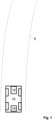
- Fig. 1 shows a vehicle 10 driving on a road 5.
- the vehicle 10 is driving along the road, primarily in an upper direction with regard to fig. 1 .
- the vehicle 10 has an environmental sensor 12, in the present case being a radar sensor.
- the radar sensor is adapted in order to sense the road 5, so that the path ahead of the vehicle 10 can be determined.
- the vehicle 10 has a control module 14 being configured to perform a method as disclosed herein.
- the control module 14 gets input data from the environmental sensor 12 and calculates a curvature of a curve ahead of the vehicle 10. It also determines a current speed of the vehicle 10 by known means, such as wheel sensors. With the curvature and the speed, an expected lateral acceleration of the vehicle 10 when driving the curve ahead of the vehicle is calculated. This expected lateral acceleration is then compared with three thresholds.
- a warning message is given to a driver of the vehicle 10 so that he reduces the speed of the vehicle 10.
- the second threshold is higher than the first threshold.
- a brake system of the vehicle 10 is activated in order to actively reduce the speed of the vehicle 10.
- the third threshold is higher than the second threshold.
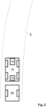
- Fig. 2 shows a vehicle 10, to which a trailer 20 is attached. It also drives on a road 5.
- the mechanisms already explained with regard to fig. 1 can be applied. However, the thresholds are lowered, so that the vehicle 10 enters the curve 5 with a lower expected lateral acceleration. This takes into account the fact that with the trailer 20, an understeer situation or an oversteer situation occurs at even lower speeds.
- inventive method can be performed in the given order. However, they can also be performed in another order, as long as this is technically reasonable.
- the inventive method can, in an embodiment, for example with a certain combination of steps, be performed in such a way that no further steps are performed. However, also other steps may be performed, including steps that are not mentioned.
Landscapes
- Engineering & Computer Science (AREA)
- Transportation (AREA)
- Mechanical Engineering (AREA)
- Automation & Control Theory (AREA)
- Chemical & Material Sciences (AREA)
- Combustion & Propulsion (AREA)
- Human Computer Interaction (AREA)
- Physics & Mathematics (AREA)
- Mathematical Physics (AREA)
- Regulating Braking Force (AREA)
Abstract
Description
- The invention relates to a method for increasing corner stability of a vehicle and to a corresponding control module.
- Vehicles typically drive on roads, which can comprise curves. In a curve, a vehicle is subject to a lateral acceleration, which may lead to understeering or oversteering. It is known that electronic stability control systems can be used in vehicles in order to reduce understeering or oversteering by selectively applying a brake force to one wheel of an axis.
- It is an object of the invention to provide for a method and a corresponding control apparatus that allows reducing the situations in which an electronic stability control has to influence the driving of the vehicle. This is achieved by a method and by a corresponding control module according to the respective main claims. Preferred embodiments may, for example, be derived from the respective dependent claims.
- The invention relates to a method for increasing corner stability of a vehicle. The method comprises the following steps:
- recognizing a course ahead of a road on which the vehicle is driving,
- determining a speed of the vehicle,
- determining an expected lateral acceleration based on the course ahead and the speed, and
- if the expected lateral acceleration exceeds a first threshold, activating a reaction.
- This allows for proactively determining if a lateral acceleration will be so high that problems with the stability of the vehicle are to be expected, and to proactively activate a reaction, wherein the reaction may, for example, reduce the risk that a problem with the stability will occur. This can reduce the numbers of activation of electronic stability control and a corresponding selective braking of one wheel of an axis.
- Corner stability is especially regarded as the stability of a vehicle when driving through a curve of a road. The corner stability may especially be regarded as an omission of understeering or oversteering situations. The course ahead of a road may especially comprise the course of the road in front of the vehicle, as, for example, it is seen on a map or from a bird's perspective. The road may be recognized, for example, by using navigation, for example satellite navigation. The road may also be recognized by using environmental sensors, for example as described further below. The speed may be determined by means like wheel sensors or satellite navigation. The speed may especially be the absolute speed over ground. The lateral acceleration may especially be calculated by using a formula, which may, for example, comprise a detected curvature or a detected radius of a curve and the speed. The first threshold may especially be set such that if the expected lateral acceleration exceeds this first threshold, a significant understeer or oversteer condition is to be expected.
- The course ahead may especially be recognized by one or more environmental sensors, for example radar, lidar and/or one or more cameras. However, also other means can be used. For example, the course ahead may be recognized by an electronic map. Also, a combination of the mentioned means or other means can be used.
- A reaction may be a warning issued to a driver of the vehicle. The warning may especially be an acoustic warning and/or an optical warning. For example, a light may be activated in order to issue the warning. Especially, the warning can advise the driver to reduce speed.
- Especially, it may be implemented that if an amount of the expected lateral acceleration exceeds a second threshold, a reaction may be reduction of engine torque. This second threshold may especially be higher than the first threshold. A reduction of engine torque may especially lead to a reduction in acceleration or to a reduction in the speed of the vehicle. This may lead to the vehicle entering the curve with less speed, and thus with less lateral acceleration.
- Especially, it may be implemented, that if an amount of the expected lateral acceleration exceeds a third threshold, a reaction may be a brake actuation. This may actively reduce the speed of the vehicle in order to reduce the lateral acceleration actually seen in the curve. Especially, the third threshold may be higher than the first threshold and/or the second threshold.
- The determining of a lateral acceleration to be expected may especially be dependent on whether a trailer is attached to the vehicle. Especially, it may be included in a calculation if a trailer may reduce effectiveness of brake action or may usually make a driver to reduce speed on his own.
- Especially, it may be implemented that one or more thresholds, especially the first threshold, the second threshold and/or the third threshold, may be dependent on whether a trailer is attached to the vehicle. Especially, the thresholds may be lower if a trailer is attached to the vehicle. This may ensure that a reaction to reduce lateral acceleration is initiated earlier compared with a situation in which no trailer is attached to the vehicle. A trailer may typically lead to an increased effect of understeer or oversteer, and thus a situation of instability may also be present at speeds lower compared with a situation in which no trailer is attached to the vehicle.
- Especially, the method may be applied in addition to corner stability control based on one-side brake actuation. Such a corner stability control may especially be a known electronic stability control. Such systems typically activate the brake of one wheel of an axis separately without activating the brake of the other wheel of this axis. Especially, such a corner stability control may activate a brake at a rear wheel on the inner side of a curve in case of an understeering. Especially, a corner stability control may activate a brake at a front wheel at an outer side of a curve in case of an oversteering. This may be used while driving through a curve in addition to the method aspects disclosed herein.
- The invention relates further to an electronic control module being configured to perform a method as disclosed herein. An electronic control module may especially be embodied as a processor or microcontroller together with a suitable storage medium storing instruction codes. It may also be implemented as application specific integrated circuit. The invention relates further to a non-transitory computer-readable storage medium comprising program code that makes a processor to perform a method as disclosed herein. With regard to the method, all disclosed embodiments and variations may be applied.
- Especially, the aspects disclosed herein relate to a potential instability scenario of a vehicle and to informing a driver in case of driver mode using sensorics. It is known that cornering stability may be maintained by electronic stability control that may react to an oversteer scenario or to an understeer scenario, especially by comparing steering wheel angle sensor and vehicle's inertial measurement unit. If a yaw rate of a vehicle is less or more than a driver's demand, it is detected as instable scenario and brakes are applied accordingly to bring the vehicle to stability. However, the known approach is only a reactive approach to instability caused already. This may have some intervention during the drive and might lead to panic of a driver.
- In a proposed method, a road curvature ahead is sensed and estimated, for example using radar. Knowing the road's curvature and vehicle's velocity, lateral acceleration may be computed and may be compared with vehicle's threshold lateral acceleration safe for cornering. If it is higher than the threshold, the following actions could be taken:
- suggest safe velocity with warning to driver via HMI (Human Machine Interface),
- reduce engine torque as second level,
- apply brake as third level.
- This method is a proactive safety to a potential instability instead of reacting to an instability. This especially has the advantages that it is a proactive warning to a potential instability, that enhanced (double layer) safety (proactive stability control and reactive stability control) is possible, and that one could take a trailer into consideration and suggest safety velocity to avoid instability.
- The invention will now be further described with respect to the accompanying drawings.
-
Fig. 1 : shows a vehicle on a road, and -
fig. 2 : shows a vehicle with a trailer on a road. -
Fig. 1 shows avehicle 10 driving on aroad 5. Thevehicle 10 is driving along the road, primarily in an upper direction with regard tofig. 1 . Thevehicle 10 has anenvironmental sensor 12, in the present case being a radar sensor. The radar sensor is adapted in order to sense theroad 5, so that the path ahead of thevehicle 10 can be determined. - The
vehicle 10 has acontrol module 14 being configured to perform a method as disclosed herein. Thecontrol module 14 gets input data from theenvironmental sensor 12 and calculates a curvature of a curve ahead of thevehicle 10. It also determines a current speed of thevehicle 10 by known means, such as wheel sensors. With the curvature and the speed, an expected lateral acceleration of thevehicle 10 when driving the curve ahead of the vehicle is calculated. This expected lateral acceleration is then compared with three thresholds. - Should the expected lateral acceleration exceed a first threshold, a warning message is given to a driver of the
vehicle 10 so that he reduces the speed of thevehicle 10. - Should the expected lateral acceleration exceed a second threshold, an engine torque of an engine driving the
vehicle 10 is reduced. The second threshold is higher than the first threshold. - Should the expected lateral acceleration exceed a third threshold, a brake system of the
vehicle 10 is activated in order to actively reduce the speed of thevehicle 10. The third threshold is higher than the second threshold. - Should the lateral acceleration actually experienced in the curve, despite these measures, be such that an oversteer or an understeer situation occurs, classical means of reducing such an oversteer or understeer may be applied, especially braking one wheel of an axis while not braking the other wheel of that axis.
-
Fig. 2 shows avehicle 10, to which atrailer 20 is attached. It also drives on aroad 5. In principle, the mechanisms already explained with regard tofig. 1 can be applied. However, the thresholds are lowered, so that thevehicle 10 enters thecurve 5 with a lower expected lateral acceleration. This takes into account the fact that with thetrailer 20, an understeer situation or an oversteer situation occurs at even lower speeds. - Mentioned steps of the inventive method can be performed in the given order. However, they can also be performed in another order, as long as this is technically reasonable. The inventive method can, in an embodiment, for example with a certain combination of steps, be performed in such a way that no further steps are performed. However, also other steps may be performed, including steps that are not mentioned.
- It is to be noted that features may be described in combination in the claims and in the description, for example in order to provide for better understandability, despite the fact that these features may be used or implemented independent from each other. The person skilled in the art will note that such features can be combined with other features or feature combinations independent from each other.
- References in dependent claims may indicate preferred combinations of the respective features, but do not exclude other feature combinations.
-
- 5
- road
- 10
- vehicle
- 12
- environmental sensor
- 14
- control module
- 20
- trailer
Claims (10)
- A method for increasing corner stability of a vehicle (10), the method comprising the following steps:- recognizing a course ahead of a road (5) on which the vehicle (10) is driving,- determining a speed of the vehicle (10),- determining a lateral acceleration to be expected based on the course ahead and the speed, and- if the expected lateral acceleration exceeds a first threshold, activating a reaction.
- Method according to claim 1,- wherein the course ahead is recognized by one or more environmental sensors (12), radar, LIDAR, and/or camera.
- Method according to one of the preceding claims,- wherein the course ahead is recognized by an electronic map.
- Method according to one of the preceding claims,- wherein a reaction is a warning issued to a driver of the vehicle (10).
- Method according to one of the preceding claims,- wherein, if an amount of the expected lateral acceleration exceeds a second threshold, a reaction is a reduction of engine torque.
- Method according to one of the preceding claims,- wherein, if an amount of the expected lateral acceleration exceeds a third threshold, a reaction is a brake actuation.
- Method according to one of the preceding claims,- wherein the determining of a lateral acceleration to be expected is dependent on whether a trailer (20) is attached to the vehicle (10).
- Method according to one of the preceding claims,- wherein one or more thresholds are dependent on whether a trailer (20) is attached to the vehicle (10).
- Method according to one of the preceding claims,- wherein the method is applied in addition to corner stability control based on one-side brake actuation.
- Electronic control module (14), being configured to perform a method according to one of the preceding claims.
Priority Applications (1)
| Application Number | Priority Date | Filing Date | Title |
|---|---|---|---|
| EP23187037.9A EP4494911B1 (en) | 2023-07-21 | 2023-07-21 | A method for increasing corner stability of a vehicle and electronic control module |
Applications Claiming Priority (1)
| Application Number | Priority Date | Filing Date | Title |
|---|---|---|---|
| EP23187037.9A EP4494911B1 (en) | 2023-07-21 | 2023-07-21 | A method for increasing corner stability of a vehicle and electronic control module |
Publications (2)
| Publication Number | Publication Date |
|---|---|
| EP4494911A1 true EP4494911A1 (en) | 2025-01-22 |
| EP4494911B1 EP4494911B1 (en) | 2026-04-01 |
Family
ID=87429503
Family Applications (1)
| Application Number | Title | Priority Date | Filing Date |
|---|---|---|---|
| EP23187037.9A Active EP4494911B1 (en) | 2023-07-21 | 2023-07-21 | A method for increasing corner stability of a vehicle and electronic control module |
Country Status (1)
| Country | Link |
|---|---|
| EP (1) | EP4494911B1 (en) |
Citations (5)
| Publication number | Priority date | Publication date | Assignee | Title |
|---|---|---|---|---|
| US20020128764A1 (en) * | 2000-04-18 | 2002-09-12 | Falk Hecker | Method and device for estimating a transverse acceleration at an axle of a semitrailer or a trailer of a vehicle combination |
| US20120109471A1 (en) * | 2010-10-27 | 2012-05-03 | Robert Bosch Gmbh | Trailer sway mitigation using torque vectoring |
| US20150197225A1 (en) * | 2012-08-24 | 2015-07-16 | Continental Teves Ag & Co. Ohg | Method and system for promoting a uniform driving style |
| WO2015178840A1 (en) * | 2014-05-21 | 2015-11-26 | Scania Cv Ab | Method and system for the adaptation of the driving of a vehicle on a roadway in association with taking a curve |
| US20220203999A1 (en) * | 2020-12-28 | 2022-06-30 | GM Global Technology Operations LLC | System and method for evaluating vehicle-trailer combination for trailer sway potential using active yaw maneuver |
Family Cites Families (1)
| Publication number | Priority date | Publication date | Assignee | Title |
|---|---|---|---|---|
| CN116252810A (en) * | 2023-05-09 | 2023-06-13 | 天津所托瑞安汽车科技有限公司 | Vehicle curve speed early warning method, device, terminal and storage medium |
-
2023
- 2023-07-21 EP EP23187037.9A patent/EP4494911B1/en active Active
Patent Citations (5)
| Publication number | Priority date | Publication date | Assignee | Title |
|---|---|---|---|---|
| US20020128764A1 (en) * | 2000-04-18 | 2002-09-12 | Falk Hecker | Method and device for estimating a transverse acceleration at an axle of a semitrailer or a trailer of a vehicle combination |
| US20120109471A1 (en) * | 2010-10-27 | 2012-05-03 | Robert Bosch Gmbh | Trailer sway mitigation using torque vectoring |
| US20150197225A1 (en) * | 2012-08-24 | 2015-07-16 | Continental Teves Ag & Co. Ohg | Method and system for promoting a uniform driving style |
| WO2015178840A1 (en) * | 2014-05-21 | 2015-11-26 | Scania Cv Ab | Method and system for the adaptation of the driving of a vehicle on a roadway in association with taking a curve |
| US20220203999A1 (en) * | 2020-12-28 | 2022-06-30 | GM Global Technology Operations LLC | System and method for evaluating vehicle-trailer combination for trailer sway potential using active yaw maneuver |
Also Published As
| Publication number | Publication date |
|---|---|
| EP4494911B1 (en) | 2026-04-01 |
Similar Documents
| Publication | Publication Date | Title |
|---|---|---|
| US11332107B2 (en) | System and method for operating redundancy braking in case of breakdown of main brake for autonomous vehicle | |
| US8086406B2 (en) | Safety system for a means of transportation and a method relating to the same | |
| US7698032B2 (en) | Automotive lane deviation prevention apparatus | |
| US8386124B2 (en) | Method and device for stabilizing a vehicle after a collision | |
| EP3674154B1 (en) | Method and apparatus for controlling travel of driving-assisted vehicle | |
| US9840242B2 (en) | Method for regulating driving stability | |
| US8296033B2 (en) | Curve-related accident mitigation | |
| US20180186372A1 (en) | Lane departure prevention apparatus | |
| US20040158377A1 (en) | Vehicle dynamics control apparatus | |
| CN103732459B (en) | Vehicle Turning Efficiency Device | |
| CN110040138B (en) | Vehicle parallel auxiliary driving method and system | |
| US20150002284A1 (en) | Driving assist controller for vehicle | |
| CN111942352A (en) | Adaptive AEB System Considering Steering Path and Its Control Method | |
| US9393959B2 (en) | Method and control unit for operating a dynamics control system of a vehicle as well as a control system for dynamics control of a vehicle using surroundings sensor data | |
| US20140379244A1 (en) | Avoidance maneuver assistant for motor vehicles | |
| CN114643991A (en) | Chassis domain control method under high-speed working condition and related device | |
| US8600639B2 (en) | Yaw rate control with simultaneous maximum deceleration | |
| CN115230685A (en) | Vehicle collision protection control method and advanced driving assistance system | |
| US20250083656A1 (en) | Braking control device | |
| JP7733553B2 (en) | Vehicle behavior control device | |
| KR102562411B1 (en) | Method for assisting a driver of an ego-vehicle when driving through a curve lying ahead | |
| US20250256703A1 (en) | Method and apparatus for activating esc of intelligent driving vehicle | |
| CN119053498A (en) | Method for setting a target distance between a motor vehicle and a preceding vehicle, computer program, controller and motor vehicle | |
| US10864919B2 (en) | Alarm apparatus for a vehicle with driving control | |
| EP4494911B1 (en) | A method for increasing corner stability of a vehicle and electronic control module |
Legal Events
| Date | Code | Title | Description |
|---|---|---|---|
| PUAI | Public reference made under article 153(3) epc to a published international application that has entered the european phase |
Free format text: ORIGINAL CODE: 0009012 |
|
| STAA | Information on the status of an ep patent application or granted ep patent |
Free format text: STATUS: THE APPLICATION HAS BEEN PUBLISHED |
|
| AK | Designated contracting states |
Kind code of ref document: A1 Designated state(s): AL AT BE BG CH CY CZ DE DK EE ES FI FR GB GR HR HU IE IS IT LI LT LU LV MC ME MK MT NL NO PL PT RO RS SE SI SK SM TR |
|
| STAA | Information on the status of an ep patent application or granted ep patent |
Free format text: STATUS: REQUEST FOR EXAMINATION WAS MADE |
|
| 17P | Request for examination filed |
Effective date: 20250722 |
|
| RAP3 | Party data changed (applicant data changed or rights of an application transferred) |
Owner name: AUMOVIO GERMANY GMBH |
|
| REG | Reference to a national code |
Ref country code: DE Ref legal event code: R079 Free format text: PREVIOUS MAIN CLASS: B60K0031000000 Ipc: B60K0031120000 Ref document number: 602023014353 Country of ref document: DE |
|
| GRAP | Despatch of communication of intention to grant a patent |
Free format text: ORIGINAL CODE: EPIDOSNIGR1 |
|
| STAA | Information on the status of an ep patent application or granted ep patent |
Free format text: STATUS: GRANT OF PATENT IS INTENDED |
|
| RIC1 | Information provided on ipc code assigned before grant |
Ipc: B60K 31/12 20060101AFI20251126BHEP Ipc: B60W 30/02 20120101ALI20251126BHEP Ipc: B60W 30/18 20120101ALI20251126BHEP Ipc: B60W 40/109 20120101ALI20251126BHEP Ipc: B60W 50/00 20060101ALI20251126BHEP Ipc: B60W 50/14 20200101ALI20251126BHEP Ipc: B60K 31/00 20060101ALI20251126BHEP |
|
| INTG | Intention to grant announced |
Effective date: 20251216 |
|
| GRAS | Grant fee paid |
Free format text: ORIGINAL CODE: EPIDOSNIGR3 |
|
| GRAA | (expected) grant |
Free format text: ORIGINAL CODE: 0009210 |
|
| STAA | Information on the status of an ep patent application or granted ep patent |
Free format text: STATUS: THE PATENT HAS BEEN GRANTED |
|
| AK | Designated contracting states |
Kind code of ref document: B1 Designated state(s): AL AT BE BG CH CY CZ DE DK EE ES FI FR GB GR HR HU IE IS IT LI LT LU LV MC ME MK MT NL NO PL PT RO RS SE SI SK SM TR |
|
| REG | Reference to a national code |
Ref country code: CH Ref legal event code: F10 Free format text: ST27 STATUS EVENT CODE: U-0-0-F10-F00 (AS PROVIDED BY THE NATIONAL OFFICE) Effective date: 20260401 Ref country code: GB Ref legal event code: FG4D |
|
| REG | Reference to a national code |
Ref country code: IE Ref legal event code: FG4D |
|
| REG | Reference to a national code |
Ref country code: DE Ref legal event code: R096 Ref document number: 602023014353 Country of ref document: DE |