EP4494897A1 - Wheel hub of an agricultural or work vehicle and hydraulic oil accumulation system including the wheel hub - Google Patents
Wheel hub of an agricultural or work vehicle and hydraulic oil accumulation system including the wheel hub Download PDFInfo
- Publication number
- EP4494897A1 EP4494897A1 EP24189641.4A EP24189641A EP4494897A1 EP 4494897 A1 EP4494897 A1 EP 4494897A1 EP 24189641 A EP24189641 A EP 24189641A EP 4494897 A1 EP4494897 A1 EP 4494897A1
- Authority
- EP
- European Patent Office
- Prior art keywords
- hydraulic
- oil
- hub
- hydraulic oil
- chamber
- Prior art date
- Legal status (The legal status is an assumption and is not a legal conclusion. Google has not performed a legal analysis and makes no representation as to the accuracy of the status listed.)
- Pending
Links
Images



Classifications
-
- B—PERFORMING OPERATIONS; TRANSPORTING
- B60—VEHICLES IN GENERAL
- B60B—VEHICLE WHEELS; CASTORS; AXLES FOR WHEELS OR CASTORS; INCREASING WHEEL ADHESION
- B60B27/00—Hubs
- B60B27/0047—Hubs characterised by functional integration of other elements
-
- B—PERFORMING OPERATIONS; TRANSPORTING
- B60—VEHICLES IN GENERAL
- B60B—VEHICLE WHEELS; CASTORS; AXLES FOR WHEELS OR CASTORS; INCREASING WHEEL ADHESION
- B60B35/00—Axle units; Parts thereof ; Arrangements for lubrication of axles
- B60B35/12—Torque-transmitting axles
-
- B—PERFORMING OPERATIONS; TRANSPORTING
- B60—VEHICLES IN GENERAL
- B60B—VEHICLE WHEELS; CASTORS; AXLES FOR WHEELS OR CASTORS; INCREASING WHEEL ADHESION
- B60B35/00—Axle units; Parts thereof ; Arrangements for lubrication of axles
- B60B35/12—Torque-transmitting axles
- B60B35/16—Axle housings
-
- B—PERFORMING OPERATIONS; TRANSPORTING
- B60—VEHICLES IN GENERAL
- B60B—VEHICLE WHEELS; CASTORS; AXLES FOR WHEELS OR CASTORS; INCREASING WHEEL ADHESION
- B60B27/00—Hubs
- B60B27/0073—Hubs characterised by sealing means
-
- B—PERFORMING OPERATIONS; TRANSPORTING
- B60—VEHICLES IN GENERAL
- B60B—VEHICLE WHEELS; CASTORS; AXLES FOR WHEELS OR CASTORS; INCREASING WHEEL ADHESION
- B60B2900/00—Purpose of invention
- B60B2900/50—Improvement of
- B60B2900/511—Sealing
-
- B—PERFORMING OPERATIONS; TRANSPORTING
- B60—VEHICLES IN GENERAL
- B60B—VEHICLE WHEELS; CASTORS; AXLES FOR WHEELS OR CASTORS; INCREASING WHEEL ADHESION
- B60B2900/00—Purpose of invention
- B60B2900/50—Improvement of
- B60B2900/561—Lubrication
Definitions
- the present invention relates to the field of wheel hubs of agricultural and work vehicles and the systems of accumulating hydraulic oil of an agricultural or work vehicle.
- Agricultural vehicles or work vehicles are well known for moving materials and performing specific heavy duty tasks. They are usually equipped with a transmission.
- a prime mover E generally an internal combustion engine, drives a variable displacement hydraulic pump HP in rotation, which feeds a hydraulic motor HM operatively connected to the hydraulic pump, defining a so-called hydrostat HY, wherein a forward hydraulic line F and a return hydraulic line R interconnect the hydraulic pump with the hydraulic motor.
- Agricultural or work vehicles also include a circuit for the implementation of "hydraulic services", i.e. hydraulic users, such as articulated arms, lifters, etc.
- hydraulic services i.e. hydraulic users, such as articulated arms, lifters, etc.
- At least one additional hydraulic pump separate from the one of the hydrostat is provided to feed the hydraulic services.
- the market request is to enhance the hydraulic capacity and the flow rate of the hydraulic pump, but also the maximum volume of oil that can be withdrawn and sent to the various hydraulic services.
- the flow of oil to the hydraulic users can be increased by installing larger hydraulic pumps, however to increase the amount of oil available, it is necessary to increase the size of the tank where the oil is collected.
- the hydraulic oil is collected in the tractor main body or transmission body. Regardless of the quantity of oil used to feed the various hydraulic services, it is always necessary to guarantee a minimum oil level in the transmission to safeguard the lubrication of the transmission itself, but at the same time, this oil level cannot exceed a predetermined limit recommended to contain the transmission power losses caused by the sloshing effect of the gears drowned in the oil.
- Another possibility to increase the available oil capacity is to adopt a secondary/auxiliary tank but, in this case, it is necessary to evaluate the feasibility considering all the other devices that must be housed on-board the vehicle.
- the object of the present invention is to propose a way to store hydraulic oil without installing further tanks.
- the basic idea of the present invention is to exploit a so-called intermediate chamber in an intermediate part of the wheel hub of an agricultural or work vehicle to realize a hydraulic oil tank.
- the hubs of work vehicles comprise a housing in which a portion of the transmission is housed in an oil bath.
- An axle comprises a pair of opposing bells and therefore, at least one gasket is provided for each of the two bells so as to define a central portion of the axle in which a bevel gear and/or a differential can be arranged lubricated in an oil bath.
- the bearing is grease lubricated which is held in place by a pair of seals to define a grease lubricated chamber.
- a first central area of the axle is defined, which confines a closed chamber to keep the axle differential in an oil bath and a third chamber, at the end of each hub, which confines the grease.
- an intermediate chamber is identified between the central area of the axle and the end area of the hub, in which a first circa radial opening is made, which allows the introduction or drawing off of hydraulic oil.
- a second opening is arranged to put the intermediate chamber in communication with the external environment by means of an aeration valve.
- an unused chamber, inside a wheel hub is used as an auxiliary hydraulic tank of the vehicle transmission and/or of the hydraulic services.
- the wheel hub H object of the present invention of an agricultural or work vehicle VEH is shown, exemplified in Fig. 4 .
- the wheel hub comprises a fixed housing BL, defining an axis of development X.
- a spindle SH is arranged inside the housing and coaxially with it, which faces the outside of the housing by means of a flange FL integral with the spindle.
- the bell is tapered towards the free end FE from which the spindle SH protrudes with the relative flange FL necessary for coupling a vehicular wheel W.
- the development axis X can also be an axis of rotation for the spindle and/or for at least one axial section of the bell.
- the flange comprises mechanical connection means SK, for example pins or threaded holes, for fixing the rim of a wheel in a per se known way.
- the spindle is rotatably associated with the bell by at least one pair of bearings B1, B2.
- the external bearing B2 is arranged proximal to the free end FE of the hub H, while the internal bearing B1 is arranged proximal to the portion of the bell which widens to be connected to the central body CB of the vehicle propulsion system.
- the external bearing is confined, in the axial direction, by an intermediate seal G2 and an external seal G3.
- the "external" designation indicates the fact that the gasket G3 faces the external environment, while the intermediate gasket G2, or the internal gasket G1 described below, borders on the intermediate chamber S2, which is completely internal to the hub, as better specified below.
- the external bearing B2 is arranged lubricated with grease; therefore, the gasket G2 and G3 are sealing for the grease contained in the end chamber S3.
- the internal bearing B1 supports the spindle SH proximal to the base of the bell which widens to be connected to the central body CB of the vehicle propulsion system.
- a gasket G1 separates the intermediate chamber S2 from a central chamber S1 of the axle, in which the internal bearing B1 is housed.
- the central chamber S1 is in an oil bath, therefore, the gasket G1 is oiltight.
- the central chamber S1 contains the hydraulic oil of the differential group DF shown schematically in figure 1 . This chamber is completely distinct and separate from the intermediate chamber S2 in which the hydraulic oil of the hydraulic transmission is collected as in an auxiliary tank.
- the bell is provided with a first opening HC, approximately radial, in correspondence with the intermediate chamber S2.
- the HC opening is associated with a hydraulic connection, indicated, for convenience, also HC.
- AHC aeration valve
- the air valve is configured to allow air to enter and leave the intermediate chamber while retaining the oil.
- the aeration valve allows the oil to flow towards the main tank housed in the central body CB, allowing air to enter the intermediate chamber from the outside.
- the first hydraulic fitting HC is arranged to be connected, by means of an external pipe P1, made for example of rubber, to the central body CB of the propulsion system.
- the first opening HC is arranged in a point such as to allow the natural outflow of the hydraulic oil from the hub towards the central body CB of the propulsion system due to the gravity force.
- the previously unused intermediate chamber S2 is exploited to create an auxiliary hydraulic oil tank.
- the intermediate chamber S2 fills and empties and the air valve AHC allows the inflow and outflow of oil according to the flow rate of the hydraulic pump which draws oil from the main tank.
- a filter can be associated with the air valve to prevent the introduction of dust into chamber S2.
- the intermediate chamber is equipped with a further opening RHC to which a second hydraulic connector is associated, referred to as the opening RHC for convenience.
- Both the first and second hydraulic connectors HC and RHC are hydraulically connected with the main tank respectively in an upper part and in a lower part of the main tank CB, in operative conditions, by means of respective pipes P1 and P2.
- the present invention does not require any particular expedients, since the intermediate chamber S2 is at ambient pressure. It is only necessary to have a gasket G2 suitable for coming into contact with the hydraulic oil intended to be collected inside the intermediate chamber S2.
- the inflow of hydraulic oil from the hub to the main tank is controlled by a solenoid valve V, while the outflow is controlled by a hydraulic return pump RP driven in rotation by a relative motor M, which can be electric or hydraulic, as shown in figure 6 .
- the control logic in any case, is based on a pair of level sensors HLS and LS associated respectively with the central body CB of the transmission and with the wheel hub H.
- the first sensor HLS is a sensor capable of detecting a minimum and a maximum level of the hydraulic oil contained in the main tank housed in the central body of the hydraulic transmission.
- the second sensor LS is only able to detect a maximum oil level inside the intermediate chamber S2 of the hub.
- Fig. 6 also shows a main hydraulic pump MP arranged to feed at least one hydraulic user YUS, such as for example a hydraulic lift, an articulated arm, a flattening blade, etc..
- a hydraulic pump MP arranged to feed at least one hydraulic user YUS, such as for example a hydraulic lift, an articulated arm, a flattening blade, etc.
- the present invention also relates to an agricultural or work vehicle comprising a wheel hub comprising a bell arranged to support a spindle and in which an intermediate chamber is formed between the bell and the spindle operatively connected to a main tank of hydraulic oil by means of at least one radial opening in the bell and more particularly by means of an external pipe P1, P2 arranged to put the intermediate chamber in communication with the main tank.
- the main hydraulic oil tank is contained in the vehicle transmission housing.
Landscapes
- Engineering & Computer Science (AREA)
- Mechanical Engineering (AREA)
- General Details Of Gearings (AREA)
Abstract
Description
- The present invention relates to the field of wheel hubs of agricultural and work vehicles and the systems of accumulating hydraulic oil of an agricultural or work vehicle.
- Agricultural vehicles or work vehicles are well known for moving materials and performing specific heavy duty tasks. They are usually equipped with a transmission. With reference to
Figure 1 , a prime mover E, generally an internal combustion engine, drives a variable displacement hydraulic pump HP in rotation, which feeds a hydraulic motor HM operatively connected to the hydraulic pump, defining a so-called hydrostat HY, wherein a forward hydraulic line F and a return hydraulic line R interconnect the hydraulic pump with the hydraulic motor. - Agricultural or work vehicles also include a circuit for the implementation of "hydraulic services", i.e. hydraulic users, such as articulated arms, lifters, etc.
- Generally, at least one additional hydraulic pump separate from the one of the hydrostat is provided to feed the hydraulic services.
- The market request is to enhance the hydraulic capacity and the flow rate of the hydraulic pump, but also the maximum volume of oil that can be withdrawn and sent to the various hydraulic services.
- The flow of oil to the hydraulic users can be increased by installing larger hydraulic pumps, however to increase the amount of oil available, it is necessary to increase the size of the tank where the oil is collected.
- Generally, the hydraulic oil is collected in the tractor main body or transmission body. Regardless of the quantity of oil used to feed the various hydraulic services, it is always necessary to guarantee a minimum oil level in the transmission to safeguard the lubrication of the transmission itself, but at the same time, this oil level cannot exceed a predetermined limit recommended to contain the transmission power losses caused by the sloshing effect of the gears drowned in the oil.
- Another possibility to increase the available oil capacity is to adopt a secondary/auxiliary tank but, in this case, it is necessary to evaluate the feasibility considering all the other devices that must be housed on-board the vehicle.
- Unless specifically excluded in the detailed description that follows, what is described in this chapter is to be considered as an integral part of the detailed description.
- The object of the present invention is to propose a way to store hydraulic oil without installing further tanks.
- The basic idea of the present invention is to exploit a so-called intermediate chamber in an intermediate part of the wheel hub of an agricultural or work vehicle to realize a hydraulic oil tank.
- More specifically, the hubs of work vehicles comprise a housing in which a portion of the transmission is housed in an oil bath. An axle comprises a pair of opposing bells and therefore, at least one gasket is provided for each of the two bells so as to define a central portion of the axle in which a bevel gear and/or a differential can be arranged lubricated in an oil bath.
- At the free end of the bell there is a spindle support bearing. The bearing is grease lubricated which is held in place by a pair of seals to define a grease lubricated chamber.
- Therefore, a first central area of the axle is defined, which confines a closed chamber to keep the axle differential in an oil bath and a third chamber, at the end of each hub, which confines the grease.
- For each hub, an intermediate chamber is identified between the central area of the axle and the end area of the hub, in which a first circa radial opening is made, which allows the introduction or drawing off of hydraulic oil. A second opening is arranged to put the intermediate chamber in communication with the external environment by means of an aeration valve.
- In other words, thanks to the present invention, an unused chamber, inside a wheel hub, is used as an auxiliary hydraulic tank of the vehicle transmission and/or of the hydraulic services.
- The dependent claims describe preferred variants of the invention, forming an integral part of the present description.
- Further objects and advantages of the present invention will become clear from the detailed description that follows of an embodiment of the same (and of its variants) and from the annexed drawings given for purely explanatory and non-limiting purposes, in which:
-
Fig. 1 shows a diagram of the hydraulic transmission of an agricultural or work vehicle; -
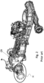
Fig. 2 shows an overall view of an example of propulsion system of an agricultural or work vehicle, according to the prior art; -
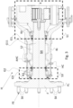
Fig. 3 shows a wheel hub according to an axial section of the propulsion system ofFig. 1 , but modified according to the present invention; -
Fig. 4 shows a working or agricultural vehicle implementing the present invention; -
Fig. 5 shows the overall view ofFig. 2 , modified according to a variant of the present invention; -
Fig. 6 schematically shows the transmission offigure 1 modified according to the present invention e -
Fig. 7 shows an exemplary flow diagram of a control method of the lubrication system object of the present invention. - The same reference numbers and letters in the figures identify the same elements or components or functions.
- It should also be noted that the terms "first", "second", "third", "superior", "inferior" and the like may be used herein to distinguish various elements. These terms do not imply a spatial, sequential, or hierarchical order for the modified items unless specifically indicated or inferred from the text.
- The elements and characteristics illustrated in the various preferred embodiments, including the drawings, can be combined with each other without however departing from the scope of protection of the present application as described below.
- With reference to
Fig. 3 , the wheel hub H object of the present invention of an agricultural or work vehicle VEH is shown, exemplified inFig. 4 . The wheel hub comprises a fixed housing BL, defining an axis of development X. A spindle SH is arranged inside the housing and coaxially with it, which faces the outside of the housing by means of a flange FL integral with the spindle. The bell is tapered towards the free end FE from which the spindle SH protrudes with the relative flange FL necessary for coupling a vehicular wheel W. - The development axis X can also be an axis of rotation for the spindle and/or for at least one axial section of the bell.
- The flange comprises mechanical connection means SK, for example pins or threaded holes, for fixing the rim of a wheel in a per se known way.
- The spindle is rotatably associated with the bell by at least one pair of bearings B1, B2.
- The external bearing B2 is arranged proximal to the free end FE of the hub H, while the internal bearing B1 is arranged proximal to the portion of the bell which widens to be connected to the central body CB of the vehicle propulsion system.
- According to the development axis X, the external bearing is confined, in the axial direction, by an intermediate seal G2 and an external seal G3. It is clear that the "external" designation indicates the fact that the gasket G3 faces the external environment, while the intermediate gasket G2, or the internal gasket G1 described below, borders on the intermediate chamber S2, which is completely internal to the hub, as better specified below.
- In the end chamber S3 defined by the pair of gaskets G2 and G3, the external bearing B2 is arranged lubricated with grease; therefore, the gasket G2 and G3 are sealing for the grease contained in the end chamber S3.
- The internal bearing B1 supports the spindle SH proximal to the base of the bell which widens to be connected to the central body CB of the vehicle propulsion system.
- A gasket G1 separates the intermediate chamber S2 from a central chamber S1 of the axle, in which the internal bearing B1 is housed. The central chamber S1 is in an oil bath, therefore, the gasket G1 is oiltight. The central chamber S1 contains the hydraulic oil of the differential group DF shown schematically in
figure 1 . This chamber is completely distinct and separate from the intermediate chamber S2 in which the hydraulic oil of the hydraulic transmission is collected as in an auxiliary tank. - According to the present invention, the bell is provided with a first opening HC, approximately radial, in correspondence with the intermediate chamber S2. The HC opening is associated with a hydraulic connection, indicated, for convenience, also HC.
- In another point of the bell there is a second opening AHC, for example radially, to which an aeration valve is associated, also indicated, for convenience, AHC.
- The air valve is configured to allow air to enter and leave the intermediate chamber while retaining the oil. Advantageously, the aeration valve allows the oil to flow towards the main tank housed in the central body CB, allowing air to enter the intermediate chamber from the outside.
- The first hydraulic fitting HC is arranged to be connected, by means of an external pipe P1, made for example of rubber, to the central body CB of the propulsion system.
- Preferably, the first opening HC is arranged in a point such as to allow the natural outflow of the hydraulic oil from the hub towards the central body CB of the propulsion system due to the gravity force.
- Advantageously, thanks to the present invention the previously unused intermediate chamber S2 is exploited to create an auxiliary hydraulic oil tank.
- The intermediate chamber S2 fills and empties and the air valve AHC allows the inflow and outflow of oil according to the flow rate of the hydraulic pump which draws oil from the main tank.
- A filter can be associated with the air valve to prevent the introduction of dust into chamber S2.
- According to another preferred variant of the invention, the intermediate chamber is equipped with a further opening RHC to which a second hydraulic connector is associated, referred to as the opening RHC for convenience. Both the first and second hydraulic connectors HC and RHC are hydraulically connected with the main tank respectively in an upper part and in a lower part of the main tank CB, in operative conditions, by means of respective pipes P1 and P2.
- It is worth pointing out that the present invention does not require any particular expedients, since the intermediate chamber S2 is at ambient pressure. It is only necessary to have a gasket G2 suitable for coming into contact with the hydraulic oil intended to be collected inside the intermediate chamber S2.
- Preferably, the inflow of hydraulic oil from the hub to the main tank is controlled by a solenoid valve V, while the outflow is controlled by a hydraulic return pump RP driven in rotation by a relative motor M, which can be electric or hydraulic, as shown in
figure 6 . - A logic for controlling the operation of the solenoid valve and the hydraulic return pump, hereinafter referred to as the "return pump", is shown in
figure 7 . - However, it is worth highlighting that the same logic of
figure 7 can be applied using a single hydraulic connection and a bidirectional pump arranged to control both the inflow and outflow of hydraulic oil. Therefore, instead of controlling the opening of the solenoid valve, the pump RP is controlled so as to allow the inflow of hydraulic oil, while the control of the pump remains unchanged in the event of an outflow of hydraulic oil. - The control logic, in any case, is based on a pair of level sensors HLS and LS associated respectively with the central body CB of the transmission and with the wheel hub H.
- The first sensor HLS is a sensor capable of detecting a minimum and a maximum level of the hydraulic oil contained in the main tank housed in the central body of the hydraulic transmission.
- The second sensor LS, on the other hand, is only able to detect a maximum oil level inside the intermediate chamber S2 of the hub.
-
Fig. 6 also shows a main hydraulic pump MP arranged to feed at least one hydraulic user YUS, such as for example a hydraulic lift, an articulated arm, a flattening blade, etc.. - With reference to
Fig. 7 , an example of hydraulic oil inflow/outflow control logic is now illustrated. - Step 1: START
- Step 2: activation of the main pump,
- Step 3: Checking if the oil level in the main body is above the minimum level, if not
- Step 4: opening of the solenoid valve and return to
Step 3, otherwise (YES), - Step 5: closing or maintaining closing of the solenoid valve V, and then
- Step 6: checking if the oil level in the main body is lower than the maximum level, if not (NO) Step 7: turn off or keep off the RP return pump and go back to
Step 3, otherwise (YES) - Step 8: checking if the oil level inside the intermediate chamber S2 has reached its maximum level, if not (NO) then Step 9: Activation or keeping active of the return pump RP and return to
step 3, otherwise (YES) - Step 10: turning off or keeping off the return pump and return to
step 1. - In summary, when the oil level inside the main tank drops below a first predetermined threshold, then hydraulic oil is recalled, inflow, from the intermediate chamber S2, vice versa when the oil level exceeds a second threshold higher than the first threshold, then, the excess oil is sent, outflow, to the intermediate chamber. In any case, the outflow is stopped if a predetermined maximum level relative to the intermediate chamber is reached.
- The present invention also relates to an agricultural or work vehicle comprising a wheel hub comprising a bell arranged to support a spindle and in which an intermediate chamber is formed between the bell and the spindle operatively connected to a main tank of hydraulic oil by means of at least one radial opening in the bell and more particularly by means of an external pipe P1, P2 arranged to put the intermediate chamber in communication with the main tank.
- More specifically, the main hydraulic oil tank is contained in the vehicle transmission housing.
- Variants of the non-limiting example described are possible, without however departing from the scope of protection of the present invention, including all equivalent embodiments for a person skilled in the art, to the contents of the claims.
- From the description given above, the person skilled in the art is capable of realizing the object of the invention without introducing further constructive details.
Claims (10)
- Wheel hub (H) of an agricultural or work vehicle comprising a fixed bell (BL) defining a development axis (X), inside which a spindle (SH) is coaxially associated in a rotatable manner, which faces the outside of the bell by means of a relative flange (FL) arranged for coupling to a vehicular propulsion wheel, a sealed intermediate chamber (S2) being defined inside the hub, and wherein the bell includes at least a first circa radial through opening (HC, RHC), equipped with a relative first hydraulic connector, arranged at said second chamber, for introducing or drawing off hydraulic oil and at least one second aeration through opening (AHC), circa radial.
- A hub according to claim 1, wherein said second aeration opening is provided with an aeration valve arranged to allow the passage of air, but not of oil.
- Hub according to claim 1, wherein the hub further comprises a third opening (RHC) and a related second hydraulic connector.
- Hub according to any one of claims 1 - 3, wherein between said bells and said spindle it comprises in succession- a first chamber (S1) for containing the hydraulic oil of a differential unit (DF), and in which a first bearing (B1) is housed in said first chamber for a rotating coupling of the spindle to the bell,- said intermediate chamber (S2), and- a third chamber (S3) in which a second bearing (B2) and a relative lubricating grease are housed.
- Hub according to claim 4, wherein said third chamber is disposed proximate to the free end (FE) of the hub when in operative conditions.
- Hub according to any one of the preceding claims, wherein said intermediate chamber (S2) is axially confined by a pair of hydraulic oil-tight seals (G1, G2).
- Vehicle axle comprising a pair of opposed hubs (H) associated so as to centrally define a chamber in an oil bath for housing a differential unit (DF), wherein each of said hubs is according to any one of claims 1 to 6.
- Agricultural or work vehicle (VEH) comprising a propulsion transmission housed in a main tank of hydraulic oil (CB) and a wheel hub (H) according to any of the claims from 1 to 6, wherein said first opening is operationally connected with its main tank through at least one hydraulic connection (P1, P2) and by means of control (V, RP) means for controlling inflow and outflow of hydraulic oil between the intermediate chamber (S2) and the main tank (CB) of hydraulic oil.
- Vehicle according to claim 8, wherein said hydraulic oil inflow and outflow control means comprise a solenoid valve (V) arranged on a first hydraulic connection (P1) and a return pump (RP) arranged on a second hydraulic connection (P2), both hydraulic connections being arranged to interconnect said intermediate chamber (S2) with said main tank by means of said first and second hydraulic connectors.
- A method of controlling the inflow and outflow of hydraulic oil between the intermediate chamber (S2) of a hub and a main hydraulic oil tank of an agricultural or work vehicle according to claim 9, the method comprising- controlling of the solenoid valve to allow the inflow of oil to the main tank when the oil level inside the main tank drops below a predetermined first threshold and vice versa- controlling of the return pump to transfer the hydraulic oil from the main tank to the intermediate chamber when the oil level inside the main tank exceeds a second threshold higher than the first threshold, and wherein the oil transfer process is stopped when a predetermined maximum level is reached inside the intermediate chamber.
Applications Claiming Priority (1)
| Application Number | Priority Date | Filing Date | Title |
|---|---|---|---|
| IT102023000015393A IT202300015393A1 (en) | 2023-07-21 | 2023-07-21 | WHEEL HUB OF AN AGRICULTURAL OR WORK VEHICLE AND HYDRAULIC OIL STORAGE SYSTEM INCLUDING THE WHEEL HUB |
Publications (1)
| Publication Number | Publication Date |
|---|---|
| EP4494897A1 true EP4494897A1 (en) | 2025-01-22 |
Family
ID=88146761
Family Applications (1)
| Application Number | Title | Priority Date | Filing Date |
|---|---|---|---|
| EP24189641.4A Pending EP4494897A1 (en) | 2023-07-21 | 2024-07-19 | Wheel hub of an agricultural or work vehicle and hydraulic oil accumulation system including the wheel hub |
Country Status (2)
| Country | Link |
|---|---|
| EP (1) | EP4494897A1 (en) |
| IT (1) | IT202300015393A1 (en) |
Citations (5)
| Publication number | Priority date | Publication date | Assignee | Title |
|---|---|---|---|---|
| US4784500A (en) * | 1987-06-25 | 1988-11-15 | Hayes Axle, Inc. | Hub lubrication system |
| WO2014155836A1 (en) * | 2013-03-29 | 2014-10-02 | 株式会社小松製作所 | Axle device for working vehicle, and working vehicle |
| US8882208B1 (en) * | 2012-03-23 | 2014-11-11 | Michael J. Lomsak | Lubrication system |
| EP3144161A1 (en) * | 2015-09-17 | 2017-03-22 | Dana Heavy Vehicle Systems Group, LLC | Wheel end assembly for a tire inflation system |
| EP3985272A1 (en) * | 2020-10-14 | 2022-04-20 | CNH Industrial Italia S.p.A. | Wheel hub for an agricultural or work vehicle |
-
2023
- 2023-07-21 IT IT102023000015393A patent/IT202300015393A1/en unknown
-
2024
- 2024-07-19 EP EP24189641.4A patent/EP4494897A1/en active Pending
Patent Citations (5)
| Publication number | Priority date | Publication date | Assignee | Title |
|---|---|---|---|---|
| US4784500A (en) * | 1987-06-25 | 1988-11-15 | Hayes Axle, Inc. | Hub lubrication system |
| US8882208B1 (en) * | 2012-03-23 | 2014-11-11 | Michael J. Lomsak | Lubrication system |
| WO2014155836A1 (en) * | 2013-03-29 | 2014-10-02 | 株式会社小松製作所 | Axle device for working vehicle, and working vehicle |
| EP3144161A1 (en) * | 2015-09-17 | 2017-03-22 | Dana Heavy Vehicle Systems Group, LLC | Wheel end assembly for a tire inflation system |
| EP3985272A1 (en) * | 2020-10-14 | 2022-04-20 | CNH Industrial Italia S.p.A. | Wheel hub for an agricultural or work vehicle |
Also Published As
| Publication number | Publication date |
|---|---|
| IT202300015393A1 (en) | 2025-01-21 |
Similar Documents
| Publication | Publication Date | Title |
|---|---|---|
| US5709135A (en) | Clam-shell shaped differential housing and lubrication system therefor | |
| EP2278191B1 (en) | Gear transmission system having a lubrication pump and a lubrication reservoir | |
| EP3330574B1 (en) | Axle assembly | |
| US6299561B1 (en) | Device for controlling level of gear lubricant as a function of speed | |
| US5855116A (en) | Combination valve including improved neutral valve for use in a hydrostatic transmission | |
| US6192682B1 (en) | Charge pump and auxiliary pump for hydrostatic transmissions and integrated hydrostatic transaxles | |
| US20110146820A1 (en) | Transmission hydraulic control system having an accumulator bypass valve assembly | |
| EP2904292B1 (en) | External lube system for a transmission | |
| US10066723B2 (en) | Driveline disconnect with modular rear driveline module (RDM) with integrated coupling and differential control | |
| AU2004203071B2 (en) | Hydraulic drive system and improved filter sub-system therefor | |
| US9593762B2 (en) | Drive axle with pump managed oil flow | |
| EP4494897A1 (en) | Wheel hub of an agricultural or work vehicle and hydraulic oil accumulation system including the wheel hub | |
| US4823637A (en) | Automatic transaxle for automotive vehicle | |
| US20070022749A1 (en) | Hydraulic drive system and improved filter sub-system therefor | |
| US12385564B2 (en) | Hydraulic arrangement | |
| CN103453051B (en) | Lock-up clutch valve control system | |
| US11473574B2 (en) | Positive displacement pump including an unloading device | |
| US11512720B2 (en) | Valve assemblies to supply fluid pressure to components in multiple transmission operating modes | |
| US10808832B1 (en) | Axle assembly with fluid storage tank | |
| CN1978950B (en) | Lubricating oil line for automatic transmission | |
| EP4034406B1 (en) | Vehicle wheel end arrangement | |
| CN222315879U (en) | Transfer case and integrated oil circuit thereof | |
| US20050016166A1 (en) | Hydraulic drive system and improved filter sub-system therefor | |
| JP2974894B2 (en) | Tractor power transmission device | |
| JP2001082404A (en) | Hydraulic drive for work machines |
Legal Events
| Date | Code | Title | Description |
|---|---|---|---|
| PUAI | Public reference made under article 153(3) epc to a published international application that has entered the european phase |
Free format text: ORIGINAL CODE: 0009012 |
|
| STAA | Information on the status of an ep patent application or granted ep patent |
Free format text: STATUS: THE APPLICATION HAS BEEN PUBLISHED |
|
| AK | Designated contracting states |
Kind code of ref document: A1 Designated state(s): AL AT BE BG CH CY CZ DE DK EE ES FI FR GB GR HR HU IE IS IT LI LT LU LV MC ME MK MT NL NO PL PT RO RS SE SI SK SM TR |
|
| STAA | Information on the status of an ep patent application or granted ep patent |
Free format text: STATUS: REQUEST FOR EXAMINATION WAS MADE |
|
| 17P | Request for examination filed |
Effective date: 20250722 |
|
| GRAP | Despatch of communication of intention to grant a patent |
Free format text: ORIGINAL CODE: EPIDOSNIGR1 |
|
| STAA | Information on the status of an ep patent application or granted ep patent |
Free format text: STATUS: GRANT OF PATENT IS INTENDED |
|
| INTG | Intention to grant announced |
Effective date: 20260119 |
|
| GRAS | Grant fee paid |
Free format text: ORIGINAL CODE: EPIDOSNIGR3 |
|
| GRAA | (expected) grant |
Free format text: ORIGINAL CODE: 0009210 |
|
| STAA | Information on the status of an ep patent application or granted ep patent |
Free format text: STATUS: THE PATENT HAS BEEN GRANTED |