EP4494855A1 - Composite lamination system and methods - Google Patents
Composite lamination system and methods Download PDFInfo
- Publication number
- EP4494855A1 EP4494855A1 EP24184202.0A EP24184202A EP4494855A1 EP 4494855 A1 EP4494855 A1 EP 4494855A1 EP 24184202 A EP24184202 A EP 24184202A EP 4494855 A1 EP4494855 A1 EP 4494855A1
- Authority
- EP
- European Patent Office
- Prior art keywords
- placement head
- fiber placement
- automated fiber
- substrate
- mandrel
- Prior art date
- Legal status (The legal status is an assumption and is not a legal conclusion. Google has not performed a legal analysis and makes no representation as to the accuracy of the status listed.)
- Pending
Links
Images




Classifications
-
- B—PERFORMING OPERATIONS; TRANSPORTING
- B32—LAYERED PRODUCTS
- B32B—LAYERED PRODUCTS, i.e. PRODUCTS BUILT-UP OF STRATA OF FLAT OR NON-FLAT, e.g. CELLULAR OR HONEYCOMB, FORM
- B32B41/00—Arrangements for controlling or monitoring lamination processes; Safety arrangements
-
- G—PHYSICS
- G01—MEASURING; TESTING
- G01B—MEASURING LENGTH, THICKNESS OR SIMILAR LINEAR DIMENSIONS; MEASURING ANGLES; MEASURING AREAS; MEASURING IRREGULARITIES OF SURFACES OR CONTOURS
- G01B11/00—Measuring arrangements characterised by the use of optical techniques
- G01B11/24—Measuring arrangements characterised by the use of optical techniques for measuring contours or curvatures
- G01B11/245—Measuring arrangements characterised by the use of optical techniques for measuring contours or curvatures using a plurality of fixed, simultaneously operating transducers
-
- B—PERFORMING OPERATIONS; TRANSPORTING
- B29—WORKING OF PLASTICS; WORKING OF SUBSTANCES IN A PLASTIC STATE IN GENERAL
- B29C—SHAPING OR JOINING OF PLASTICS; SHAPING OF MATERIAL IN A PLASTIC STATE, NOT OTHERWISE PROVIDED FOR; AFTER-TREATMENT OF THE SHAPED PRODUCTS, e.g. REPAIRING
- B29C70/00—Shaping composites, i.e. plastics material comprising reinforcements, fillers or preformed parts, e.g. inserts
- B29C70/04—Shaping composites, i.e. plastics material comprising reinforcements, fillers or preformed parts, e.g. inserts comprising reinforcements only, e.g. self-reinforcing plastics
- B29C70/28—Shaping operations therefor
- B29C70/30—Shaping by lay-up, i.e. applying fibres, tape or broadsheet on a mould, former or core; Shaping by spray-up, i.e. spraying of fibres on a mould, former or core
-
- B—PERFORMING OPERATIONS; TRANSPORTING
- B29—WORKING OF PLASTICS; WORKING OF SUBSTANCES IN A PLASTIC STATE IN GENERAL
- B29C—SHAPING OR JOINING OF PLASTICS; SHAPING OF MATERIAL IN A PLASTIC STATE, NOT OTHERWISE PROVIDED FOR; AFTER-TREATMENT OF THE SHAPED PRODUCTS, e.g. REPAIRING
- B29C70/00—Shaping composites, i.e. plastics material comprising reinforcements, fillers or preformed parts, e.g. inserts
- B29C70/04—Shaping composites, i.e. plastics material comprising reinforcements, fillers or preformed parts, e.g. inserts comprising reinforcements only, e.g. self-reinforcing plastics
- B29C70/28—Shaping operations therefor
- B29C70/30—Shaping by lay-up, i.e. applying fibres, tape or broadsheet on a mould, former or core; Shaping by spray-up, i.e. spraying of fibres on a mould, former or core
- B29C70/38—Automated lay-up, e.g. using robots, laying filaments according to predetermined patterns
-
- B—PERFORMING OPERATIONS; TRANSPORTING
- B29—WORKING OF PLASTICS; WORKING OF SUBSTANCES IN A PLASTIC STATE IN GENERAL
- B29C—SHAPING OR JOINING OF PLASTICS; SHAPING OF MATERIAL IN A PLASTIC STATE, NOT OTHERWISE PROVIDED FOR; AFTER-TREATMENT OF THE SHAPED PRODUCTS, e.g. REPAIRING
- B29C70/00—Shaping composites, i.e. plastics material comprising reinforcements, fillers or preformed parts, e.g. inserts
- B29C70/04—Shaping composites, i.e. plastics material comprising reinforcements, fillers or preformed parts, e.g. inserts comprising reinforcements only, e.g. self-reinforcing plastics
- B29C70/28—Shaping operations therefor
- B29C70/30—Shaping by lay-up, i.e. applying fibres, tape or broadsheet on a mould, former or core; Shaping by spray-up, i.e. spraying of fibres on a mould, former or core
- B29C70/38—Automated lay-up, e.g. using robots, laying filaments according to predetermined patterns
- B29C70/382—Automated fiber placement [AFP]
-
- B—PERFORMING OPERATIONS; TRANSPORTING
- B29—WORKING OF PLASTICS; WORKING OF SUBSTANCES IN A PLASTIC STATE IN GENERAL
- B29C—SHAPING OR JOINING OF PLASTICS; SHAPING OF MATERIAL IN A PLASTIC STATE, NOT OTHERWISE PROVIDED FOR; AFTER-TREATMENT OF THE SHAPED PRODUCTS, e.g. REPAIRING
- B29C70/00—Shaping composites, i.e. plastics material comprising reinforcements, fillers or preformed parts, e.g. inserts
- B29C70/04—Shaping composites, i.e. plastics material comprising reinforcements, fillers or preformed parts, e.g. inserts comprising reinforcements only, e.g. self-reinforcing plastics
- B29C70/28—Shaping operations therefor
- B29C70/54—Component parts, details or accessories; Auxiliary operations, e.g. feeding or storage of prepregs or SMC after impregnation or during ageing
-
- G—PHYSICS
- G01—MEASURING; TESTING
- G01B—MEASURING LENGTH, THICKNESS OR SIMILAR LINEAR DIMENSIONS; MEASURING ANGLES; MEASURING AREAS; MEASURING IRREGULARITIES OF SURFACES OR CONTOURS
- G01B11/00—Measuring arrangements characterised by the use of optical techniques
- G01B11/002—Measuring arrangements characterised by the use of optical techniques for measuring two or more coordinates
-
- G—PHYSICS
- G01—MEASURING; TESTING
- G01S—RADIO DIRECTION-FINDING; RADIO NAVIGATION; DETERMINING DISTANCE OR VELOCITY BY USE OF RADIO WAVES; LOCATING OR PRESENCE-DETECTING BY USE OF THE REFLECTION OR RERADIATION OF RADIO WAVES; ANALOGOUS ARRANGEMENTS USING OTHER WAVES
- G01S17/00—Systems using the reflection or reradiation of electromagnetic waves other than radio waves, e.g. lidar systems
- G01S17/02—Systems using the reflection of electromagnetic waves other than radio waves
- G01S17/06—Systems determining position data of a target
- G01S17/42—Simultaneous measurement of distance and other co-ordinates
-
- G—PHYSICS
- G01—MEASURING; TESTING
- G01S—RADIO DIRECTION-FINDING; RADIO NAVIGATION; DETERMINING DISTANCE OR VELOCITY BY USE OF RADIO WAVES; LOCATING OR PRESENCE-DETECTING BY USE OF THE REFLECTION OR RERADIATION OF RADIO WAVES; ANALOGOUS ARRANGEMENTS USING OTHER WAVES
- G01S17/00—Systems using the reflection or reradiation of electromagnetic waves other than radio waves, e.g. lidar systems
- G01S17/66—Tracking systems using electromagnetic waves other than radio waves
-
- G—PHYSICS
- G01—MEASURING; TESTING
- G01S—RADIO DIRECTION-FINDING; RADIO NAVIGATION; DETERMINING DISTANCE OR VELOCITY BY USE OF RADIO WAVES; LOCATING OR PRESENCE-DETECTING BY USE OF THE REFLECTION OR RERADIATION OF RADIO WAVES; ANALOGOUS ARRANGEMENTS USING OTHER WAVES
- G01S17/00—Systems using the reflection or reradiation of electromagnetic waves other than radio waves, e.g. lidar systems
- G01S17/86—Combinations of lidar systems with systems other than lidar, radar or sonar, e.g. with direction finders
-
- G—PHYSICS
- G01—MEASURING; TESTING
- G01S—RADIO DIRECTION-FINDING; RADIO NAVIGATION; DETERMINING DISTANCE OR VELOCITY BY USE OF RADIO WAVES; LOCATING OR PRESENCE-DETECTING BY USE OF THE REFLECTION OR RERADIATION OF RADIO WAVES; ANALOGOUS ARRANGEMENTS USING OTHER WAVES
- G01S17/00—Systems using the reflection or reradiation of electromagnetic waves other than radio waves, e.g. lidar systems
- G01S17/88—Lidar systems specially adapted for specific applications
-
- G—PHYSICS
- G05—CONTROLLING; REGULATING
- G05B—CONTROL OR REGULATING SYSTEMS IN GENERAL; FUNCTIONAL ELEMENTS OF SUCH SYSTEMS; MONITORING OR TESTING ARRANGEMENTS FOR SUCH SYSTEMS OR ELEMENTS
- G05B19/00—Program-control systems
- G05B19/02—Program-control systems electric
- G05B19/18—Numerical control [NC], i.e. automatically operating machines, in particular machine tools, e.g. in a manufacturing environment, so as to execute positioning, movement or co-ordinated operations by means of program data in numerical form
- G05B19/401—Numerical control [NC], i.e. automatically operating machines, in particular machine tools, e.g. in a manufacturing environment, so as to execute positioning, movement or co-ordinated operations by means of program data in numerical form characterised by control arrangements for measuring, e.g. calibration and initialisation, measuring workpiece for machining purposes
-
- B—PERFORMING OPERATIONS; TRANSPORTING
- B29—WORKING OF PLASTICS; WORKING OF SUBSTANCES IN A PLASTIC STATE IN GENERAL
- B29L—INDEXING SCHEME ASSOCIATED WITH SUBCLASS B29C, RELATING TO PARTICULAR ARTICLES
- B29L2031/00—Other particular articles
- B29L2031/30—Vehicles, e.g. ships or aircraft, or body parts thereof
- B29L2031/3076—Aircrafts
-
- B—PERFORMING OPERATIONS; TRANSPORTING
- B32—LAYERED PRODUCTS
- B32B—LAYERED PRODUCTS, i.e. PRODUCTS BUILT-UP OF STRATA OF FLAT OR NON-FLAT, e.g. CELLULAR OR HONEYCOMB, FORM
- B32B41/00—Arrangements for controlling or monitoring lamination processes; Safety arrangements
- B32B2041/06—Starting the lamination machine or method
Definitions
- the present disclosure relates generally to manufacturing and more specifically to composite lamination.
- layers of composite material are typically laid up on a mandrel or other.
- the layers may be laid up in the form of tape, tows, or other suitable forms.
- resin may be infused or pre-impregnated into the fiber layers.
- Composite materials with resin pre-impregnated are commonly referred to as prepreg.
- the different layers of prepreg may be laid up in different orientations and different numbers of layers may be used depending on the thickness of the composite structure being manufactured. These layers may be laid up using automated lamination equipment such as a tape laminating machine or a fiber placement system.
- Composite lamination involves some variations.
- the variations can compound in the layers of composite material.
- Laps, gaps, or other inconsistencies can result in the composite part due to variations.
- An example of the present disclosure provides a system for indexing an automated fiber placement head to a surface of a substrate.
- the system comprises a first measurement system comprising a first plurality of sensors configured to scan the surface of the substrate, a second measurement system comprising a second plurality of sensors configured to locate the automated fiber placement head, and a data management device configured to generate a full resolution transformation using measurements from the first measurement system and determine a position of the automated fiber placement head using data from the second measurement system.
- the first plurality of sensors may comprise one or more of an array of light detection and ranging (LIDAR) devices, an array of special phase imaging sensors, an array of time-of-flight sensors, an array of stereoscopic cameras, an array of light field cameras, or an array of high resolution cameras.
- LIDAR light detection and ranging
- the second plurality of sensors may comprise one or more of an array of light detection and ranging (LIDAR) devices, an array of special phase imaging sensors, an array of time-of-flight sensors, an array of stereoscopic cameras, an array of light field cameras, or an array of high resolution cameras.
- LIDAR light detection and ranging
- the system may further comprise a tracking target connected to the automated fiber placement head, the second plurality of sensors configured to track locations of the tracking target.
- the substrate may be a composite layer on a mandrel, wherein the data management device may be configured to determine thicknesses of the composite layer using measurements from the first plurality of sensors.
- the substrate may be a composite layer on a mandrel, wherein the data management device may be configured to form a model of the composite layer near real-time to generation of (i.e., generating) measurements by the first measurement system.
- an accuracy of the model of the composite layer is within about 127 ⁇ m (0.005 inches) to the composite layer.
- the substrate may be a mandrel
- the data management device may be further configured to index the automated fiber placement head to the mandrel using the full resolution transformation and the position of the automated fiber placement head.
- the first measurement system may be configured to perform both indexing and real time monitoring.
- the second measurement system may be configured to perform real time monitoring.
- Another example of the present disclosure provides a method of performing composite lamination.
- An initial mandrel scan of a substrate within a manufacturing environment is performed using a first measurement system.
- a position, preferably an initial position, of an automated fiber placement head within the manufacturing environment is determined using a second measurement system.
- a full resolution transformation is generated using results from the initial mandrel scan.
- Layup on the substrate is begun by the automated fiber placement head based on the full resolution transformation and the position, preferably the initial position.
- Performing the initial mandrel scan may comprise scanning a composite layer present on a mandrel.
- the method may comprise monitoring the position, preferably the initial position, of the automated fiber placement head during the layup using a second measurement system.
- the method further comprises adjusting the position, preferably the initial position, of the automated fiber placement head during the layup based on the monitoring by the second measurement system.
- the method may further comprise scanning composite material laid down by the automated fiber placement head by the first measurement system while the automated fiber placement head performs the layup.
- the method further comprises modifying a future layup plan based on the scan of the composite material laid down by the automated fiber placement head.
- Performing the initial mandrel scan may comprise scanning the substrate using at least one of an array of light detection and ranging (LIDAR) devices, an array of special phase imaging sensors, an array of time-of-flight sensors, an array of stereoscopic cameras, an array of light field cameras, or an array of high resolution cameras.
- LIDAR light detection and ranging
- the first measurement system may be accurate to less than or equal to about 127 ⁇ m (0.005 inches), wherein the initial mandrel scan may be performed with a frame rate with an accuracy of about 254 ⁇ m (0.010 inches).
- Another example of the present disclosure provides a method of performing composite lamination.
- a surface of a substrate is scanned to generate first measurements, and/or preferably an initial mandrel scan, using a first plurality of sensors.
- An automated fiber placement head is located using a second plurality of sensors.
- the automated fiber placement head is indexed to the substrate based on the first measurements, and/or preferably the initial mandrel scan.
- Composite material is laid up on the surface of the substrate using the automated fiber placement head after indexing the automated fiber placement head.
- the method may further comprise computing a full resolution transformation for moving the automated fiber placement head to provide substantial design conformity between the first measurements, and/or preferably the initial mandrel scan, and a layup plan for the automated fiber placement head, and moving the automated fiber placement head according to the full resolution transformation.
- the method further comprises utilizing the first measurements, and/or preferably the initial mandrel scan, to modify a first layup plan for the automated fiber placement head, the first layup plan having a first tool path for laying down composite material on the substrate.
- the substrate may be a mandrel, wherein scanning the surface of the substrate may comprise scanning a layup surface of the mandrel.
- the substrate may be a composite layer on a mandrel, wherein scanning the surface of the substrate comprises scanning the composite layer, and further comprising (determining) thicknesses of the composite layer using measurements from the first plurality of sensors.
- the first plurality of sensors may be accurate to less than or equal to about 127 ⁇ m (0.005 inches), wherein the scanning may be performed with a frame rate with an accuracy of about 254 ⁇ m (0.010 inches).
- the illustrative examples recognize and take into account several considerations. For example, the illustrative examples recognize and take into account that currently probing is performed on a mandrel prior to laying up composite material. The illustrative examples recognize and take into account that probing can take more than an hour on large parts. The illustrative examples recognize and take into account that probing only provides data at probe points. Probe points have spacing between each point. In some examples, the distance between probe points is between four and eight feet. In some examples, there can be up to fifty probe points for a large tool. Currently linear interpolations (transforms) occur between the probe points.
- the illustrative examples recognize and take into account that increasing accuracy of composite material layup will reduce defects.
- the illustrative examples provide a system and methods that will reduce or eliminate linear interpolation of the mandrel.
- the illustrative examples increase the accuracy of composite layup by increasing the accuracy of measurements of the mandrel.
- the illustrative examples provide accuracy to at least about 254 ⁇ m (0.010").
- the illustrative examples provide accuracy of a value sufficient to reduce or prevent gaps and laps in composite material laid up on the radii of the mandrel.
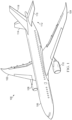
- Aircraft 100 has wing 102 and wing 104 attached to body 106. Aircraft 100 includes engine 108 attached to wing 102 and engine 110 attached to wing 104.
- Body 106 has tail section 112. Horizontal stabilizer 114, horizontal stabilizer 116, and vertical stabilizer 118 are attached to tail section 112 of body 106.
- Aircraft 100 is an example of an aircraft that can have composite parts laid up using the illustrative examples. Aircraft 100 is an example of an aircraft with a spar, a stiffener, or other composite part laid up using a method of the illustrative examples. Aircraft 100 is an example of an aircraft with a spar, a stiffener, or other composite part laid up using a system of the illustrative examples.
- System 202 in manufacturing environment 200 can be used to layup a composite part of aircraft 100 of Figure 1 .
- System 202 can be used for indexing 258 automated fiber placement head 230 to surface 234 of substrate 232.
- System 202 comprises first measurement system 204, second measurement system 206, and data management device 207.
- First measurement system 204 comprises first plurality of sensors 210 configured to scan surface 234 of substrate 232.
- first measurement system 204 can be referred to as first metrology system 208.
- Second measurement system 206 system comprises second plurality of sensors 214 configured to locate automated fiber placement head 230.
- second measurement system 206 can be referred to as second metrology system 212.
- Data management device 207 is configured to generate full resolution transformation 276 using measurements 246 from first measurement system 204 and determine position 250 of automated fiber placement head 230 using data from second measurement system 206.
- full resolution transformation 276 has sufficient measurements 246 provided by first measurement system 204 so that interpolation is not performed.
- first plurality of sensors 210 is accurate to less than or equal to about 127 ⁇ m (0.005 inches).
- scanning of substrate 232 is performed with a frame rate with an accuracy of about 254 ⁇ m (0.010 inches).
- first plurality of sensors 210 comprises one or more of array of light detection and ranging (LIDAR) devices 218, array of special phase imaging sensors 220, array of time-of-flight sensors 222, array of stereoscopic cameras 224, array of light field cameras 226, or array of high resolution cameras 228.
- second plurality of sensors comprises one or more of array of light detection and ranging (LIDAR) devices 218, array of special phase imaging sensors 220, array of time-of-flight sensors 222, array of stereoscopic cameras 224, array of light field cameras 226, or array of high resolution cameras 228.
- Substrate 232 can take the form of either mandrel 236 with layup surface 238 or composite layer 240 positioned on mandrel 236.
- first measurement system 204 scans surface 242 of composite layer 240.
- first measurement system 204 scans layup surface 238 of mandrel 236.
- composite layer 240 is a partial ply and both surface 242 and exposed portions of layup surface 238 are scanned by first measurement system 204.
- First measurement system 204 performs initial mandrel scan 256 on substrate 232. After performing initial mandrel scan 256, full resolution transformation 276 is performed using measurements 246 from initial mandrel scan 256.
- Indexing 258 automated fiber placement head 230 to substrate 232 is performed using time 260 considerably less than conventional processes due to initial mandrel scan 256 taking less time than physically probing mandrel 236. Time 260 for indexing 258 can be considerably less than indexing using probing.
- second measurement system 206 directly tracks automated fiber placement head 230 in manufacturing environment 200.
- tracking target 252 is connected to the automated fiber placement head 230.
- second plurality of sensors 214 is configured to track locations of tracking target 252.
- tracking target 252 can be a reflector.
- substrate 232 is a composite layer 240 on a mandrel 236, and data management device 207 is configured to determine thicknesses 241 of composite layer 240 using measurements 246 from the first plurality of sensors 210. In these illustrative examples, thicknesses 241 of composite layer 240 can be used to modify first layup plan 264.
- First layup plan 264 comprises first tool path 266 and compactions 268.
- at least one of first tool path 266 and compactions 268 can be modified based on thicknesses 241 of composite layer 240.
- first layup plan 264 build-up of inconsistencies in a composite part can be reduced or prevented.
- additional inconsistencies in a composite part can be reduced.
- substrate 232 is composite layer 240 on mandrel 236, and data management device 207 is configured to form model 278 of composite layer 240 near real-time to generation of measurements 246 by first measurement system 204.
- model 278 can be used in real time monitoring 262.
- accuracy 280 of model 278 of composite layer 240 is within about 127 ⁇ m (0.005 inches) to composite layer 240.
- future layup plan 270 is modified based on model 278.
- substrate 232 is mandrel 236, and data management device 207 is further configured to index automated fiber placement head 230 to mandrel 236 using the full resolution transformation 276 and position 250 of automated fiber placement head 230.
- data 248 from second measurement system 206 has higher accuracy than the accuracy of machine controller 254.
- first measurement system 204 is configured to perform both indexing 258 and real time monitoring 262.
- measurements 246 can be taken of composite material 244 laid down by automated fiber placement head 230 as composite material 244 on substrate 232.
- composite material 244 can be used to modify future layup plan 270.
- Future layup plan 270 comprises second tool path 272 and compactions 274.
- at least one of second tool path 272 and compactions 274 can be modified based on the layup of composite material 244.
- future layup plan 270 build-up of inconsistencies in a composite part can be reduced or prevented.
- future layup plan 270 additional inconsistencies in a composite part can be reduced.
- second measurement system 206 is configured to perform real time monitoring 262.
- Real time monitoring 262 of automated fiber placement head 230 can continually track position 250 of automated fiber placement head 230.
- Real time monitoring 262 of automated fiber placement head 230 can have a higher accuracy than tracking by machine controller 254 of automated fiber placement head 230.
- system 202 can be described as comprising plurality of sensors 216 configured to perform initial mandrel scan 256 and locate automated fiber placement head 230.
- first plurality of sensors 210 and second plurality of sensors 214 are sensors within sensors 216.
- manufacturing environment 200 in Figure 2 is not meant to imply physical or architectural limitations to the manner in which an illustrative example may be implemented.
- Other components in addition to or in place of the ones illustrated may be used. Some components may be unnecessary.
- the blocks are presented to illustrate some functional components. One or more of these blocks may be combined, divided, or combined and divided into different blocks when implemented in an illustrative example.
- multiple sequential layers of composite material can be laid down on mandrel 236.
- additional layup plans are present for laying up the additional composite material layers on mandrel 236.
- Manufacturing environment 300 is a physical implementation of manufacturing environment 200 of Figure 2 . Portions of aircraft 100 can be manufactured in manufacturing environment 300.
- Automated fiber placement head 302 is present in manufacturing environment 300. Automated fiber placement head 302 is configured to lay down composite material on a substrate, such as substrate 304.
- substrate 304 takes the form of mandrel 306.
- First measurement system 308 and second measurement system 310 are present in manufacturing environment 300.
- First measurement system 308 and second measurement system 310 can be used to increase accuracy of composite material layup on substrate 304.
- First measurement system 308 can be used for indexing automated fiber placement head 302 to mandrel 306.
- First measurement system 308 can be used for real time monitoring of the composite material laid up on mandrel 306.
- Second measurement system 310 is configured to determine a position of automated fiber placement head 302. Second measurement system 310 can be used for indexing automated fiber placement head 302 to mandrel 306 prior to laying down composite material. In some illustrative examples, second measurement system 310 can be used for real time monitoring of automated fiber placement head 302.
- First measurement system 308 comprises first plurality of sensors 312 configured to scan the surface of substrate 304.
- First plurality of sensors 312 comprises one or more of an array of light detection and ranging (LIDAR) devices, an array of special phase imaging sensors, an array of time-of-flight sensors, an array of stereoscopic cameras, an array of light field cameras, or an array of high resolution cameras.
- Second measurement system 310 comprises second plurality of sensors 314 configured to locate automated fiber placement head 302.
- Second plurality of sensors 314 comprises one or more of an array of light detection and ranging (LIDAR) devices, an array of special phase imaging sensors, an array of time-of-flight sensors, an array of stereoscopic cameras, an array of light field cameras, or an array of high resolution cameras.
- LIDAR light detection and ranging
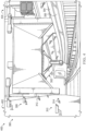
- first plurality of sensors 312 of first measurement system 308 and second plurality of sensors 314 of second measurement system 310 are depicted from a longitudinal direction of mandrel 306.
- first plurality of sensors 312 and second plurality of sensors 314 are distributed along a length of substrate 304.
- first plurality of sensors 312 and second plurality of sensors 314 are distributed along a length of substrate 304.
- the entirety of substrate 304 can be scanned.
- the accuracy of indexing is greater than probing as discrete locations and performing interpolations.
- automated fiber placement head 302 can be located at any processing location within manufacturing environment 300.
- second plurality of sensors 314 can be used for initial indexing as well as real time monitoring of automated fiber placement head 302 along the length of substrate 304.
- first plurality of sensors 312 and second plurality of sensors 314 are distributed on two sides of substrate 304.
- first plurality of sensors 312 and second plurality of sensors 314 are distributed on side wall 402 and side wall 404.
- substrate 304 is positioned between side wall 402 and side wall 404 and automated fiber placement head 302 moves in between side wall 402 and side wall 404 to layup composite material on substrate 304.
- first plurality of sensors 312 and second plurality of sensors 314 are depicted as mounted directly to side wall 402 and side wall 404, first plurality of sensors 312 and second plurality of sensors 314 can be mounted in other ways. In some illustrative examples, at least one sensor of at least one of first plurality of sensors 312 and second plurality of sensors 314 can be mounted to a stand between side wall 402 and side wall 404.
- Method 500 can be used to layup a composite part of aircraft 100 of
- Method 500 can be implemented using system 202 in manufacturing environment 200 of Figure 2 .
- Method 500 can be implemented using first measurement system 308 and second measurement system 310 in manufacturing environment 300 of Figures 3 and 4 .
- Method 500 performs an initial mandrel scan of a substrate within a manufacturing environment using a first measurement system (operation 502 ).
- Method 500 determines a position of an automated fiber placement head within the manufacturing environment using a second measurement system (operation 504).
- Method 500 generates a full resolution transformation using results from the initial mandrel scan (operation 506 ).
- Method 500 begins a layup on the substrate by the automated fiber placement head based on the full resolution transformation and the position (operation 508 ). Afterwards, method 500 terminates.
- method 500 comprises moving the mandrel into the manufacturing environment having the automated fiber placement head (operation 510 ).
- performing the initial mandrel scan comprises scanning a surface of the mandrel.
- performing the initial mandrel scan comprises scanning a composite layer present on a mandrel (operation 512 ). In some illustrative examples, performing the initial mandrel scan comprises determining a thickness of the composite layer present on the mandrel.
- method 500 monitors the position of the automated fiber placement head during the layup using a second measurement system (operation 514 ). In some illustrative examples, method 500 adjusts the position of the automated fiber placement head during the layup based on the monitoring by the second measurement system (operation 516 ).
- method 500 scans composite material laid down by the automated fiber placement head by the first measurement system while the automated fiber placement head performs the layup (operation 518 ).
- the composite material can be inspected for any inconsistencies.
- future separate indexing steps can be reduced or eliminated.
- by scanning the composite material laid down by the automated fiber placement head during the layup data for the substrate surface comprising the composite material is obtained during processing to reduce downtime.
- method 500 modifies a future layup plan based on the scan of the composite material laid down by the automated fiber placement head (operation 520 ).
- a future layup plan can be a plan to lay down a subsequent composite material.
- a future tool path to lay down the subsequent composite material may be modified to take into account the physical layup of the composite material.
- stack up of inconsistencies in a thickness of a composite layup can be reduced by taking into account the location and dimensions of the as-laid composite material.
- performing the initial mandrel scan comprises scanning the substrate using at least one of an array of light detection and ranging (LIDAR) devices, an array of special phase imaging sensors, an array of time-of-flight sensors, an array of stereoscopic cameras, an array of light field cameras, or an array of high resolution cameras (operation 522 ).
- the first measurement system is accurate to less than or equal to about 127 ⁇ m (0.005 inches), and wherein the initial mandrel scan is performed with a frame rate with an accuracy of about 254 ⁇ m (0.010 inches) (operation 524) .
- Method 600 can be used to layup a composite part of aircraft 100 of Figure 1 .
- Method 600 can be implemented using system 202 in manufacturing environment 200 of Figure 2 .
- Method 600 can be implemented using first measurement system 308 and second measurement system 310 in manufacturing environment 300 of Figures 3 and 4 .
- Method 600 scans a surface of a substrate to generate first measurements using a first plurality of sensors (operation 602 ).
- Method 600 locates an automated fiber placement head using a second plurality of sensors (operation 604 ).
- Method 600 indexes the automated fiber placement head to the substrate based on the first measurements (operation 606 ).
- Method 600 lays up composite material on the surface of the substrate using the automated fiber placement head after indexing the automated fiber placement head (operation 608 ). Afterwards, method 600 terminates.
- method 600 computes a full resolution transformation for moving the automated fiber placement head to provide substantial design conformity between the first measurements and a layup plan for the automated fiber placement head (operation 610 ). In some illustrative examples, method 600 moves the automated fiber placement head according to the full resolution transformation (operation 612 ). In some illustrative examples, method 600 comprises utilizing the first measurements to modify a first layup plan for the automated fiber placement head, the first layup plan having a first tool path for laying down composite material on the substrate (operation 614 ).
- the substrate is a mandrel, and wherein scanning the surface of the substrate comprises scanning a layup surface of the mandrel (operation 616 ).
- the substrate is a composite layer on a mandrel, wherein scanning the surface of the substrate comprises scanning the composite layer, and further comprising: determining thicknesses of the composite layer using measurements from the first plurality of sensors (operation 618 ).
- the first plurality of sensors is accurate to less than or equal to about 127 ⁇ m (0.005 inches), and wherein the scanning is performed with a frame rate with an accuracy of about 254 ⁇ m (0.010 inches) (operation 620 ).
- scanning using the first plurality of sensors can be used to increase the quality of a resulting composite part.
- the first plurality of sensors can be used to reduce inconsistencies in the resulting composite part.
- the phrase "at least one of,” when used with a list of items, means different combinations of one or more of the listed items may be used and only one of each item in the list may be needed.
- “at least one of item A, item B, or item C” may include, without limitation, item A, item A and item B, or item B. This example also may include item A, item B, and item C or item B and item C. Of course, any combinations of these items may be present.
- "at least one of” may be, for example, without limitation, two of item A; one of item B; and ten of item C; four of item B and seven of item C; or other suitable combinations.
- the item may be a particular object, thing, or a category. In other words, at least one of means any combination items and number of items may be used from the list but not all of the items in the list are required.
- each block in the flowcharts or block diagrams may represent at least one of a module, a segment, a function, or a portion of an operation or step.
- the function or functions noted in the blocks may occur out of the order noted in the figures.
- two blocks shown in succession may be executed substantially concurrently, or the blocks may sometimes be performed in the reverse order, depending upon the functionality involved.
- other blocks may be added in addition to the illustrated blocks in a flowchart or block diagram. Some blocks may be optional.
- operation 510 through operation 524 may be optional.
- operation 610 through operation 620 may be optional.
- aircraft manufacturing and service method 700 may be described in the context of aircraft manufacturing and service method 700 as shown in Figure 7 and aircraft 800 as shown in Figure 8 .
- Figure 7 an illustration of an aircraft manufacturing and service method in a form of a block diagram is depicted in accordance with an illustrative example.
- aircraft manufacturing and service method 700 may include specification and design 702 of aircraft 800 in Figure 8 and material procurement 704.
- aircraft 800 During production, component and subassembly manufacturing 706 and system integration 708 of aircraft 800 takes place. Thereafter, aircraft 800 may go through certification and delivery 710 in order to be placed in service 712. While in service 712 by a customer, aircraft 800 is scheduled for routine maintenance and service 714, which may include modification, reconfiguration, refurbishment, or other maintenance and service.
- Each of the processes of aircraft manufacturing and service method 700 may be performed or carried out by a system integrator, a third party, and/or an operator.
- the operator may be a customer.
- a system integrator may include, without limitation, any number of aircraft manufacturers and major-system subcontractors
- a third party may include, without limitation, any number of vendors, subcontractors, and suppliers
- an operator may be an airline, a leasing company, a military entity, a service organization, and so on.
- aircraft 800 is produced by aircraft manufacturing and service method 700 of Figure 7 and may include airframe 802 with plurality of systems 804 and interior 806.
- systems 804 include one or more of propulsion system 808, electrical system 810, hydraulic system 812, and environmental system 814. Any number of other systems may be included.
- Apparatuses and methods embodied herein may be employed during at least one of the stages of aircraft manufacturing and service method 700.
- One or more illustrative examples may be manufactured or used during at least one of component and subassembly manufacturing 706, system integration 708, in service 712, or maintenance and service 714 of Figure 7 .
- the illustrative examples present a system and methods for composite lamination.
- the illustrative examples present better positioning of lamination head relative to contour or cornered parts during lamination and compaction.
- the illustrative examples can perform the following method Move Layup Mandrel (LM)- Perform LM and head Scan- Generate full resolution transform- Begin Layup- Adjust lamination head as needed to conform to part.
- LM Move Layup Mandrel
- the illustrative examples provide a more accurate and rapid way of constantly indexing the lamination equipment to the layup mandrel and as-is condition of the part.
- the illustrative examples enable high rate composite manufacturing.
- the illustrative examples reduce or eliminate probing, which is a time constraint.
- indexing operations For a linear flow fabrication line, multiple indexing operations will be utilized.
- the illustrative examples enable rapid indexing. In some illustrative examples, the indexing can be performed in approximately 15 minutes.
- the illustrative examples provide full mesh resolution and eliminates the need for linear interpretations between probe points.
- the illustrative examples can continuously monitor in case of any changes during the build (collisions, movement, etc.). Varying levels of compaction for contoured parts affects the nominal surface definition. Continuously monitoring can monitor for nominal surface definition due to the varying levels of compaction.
- the illustrative examples can also monitor relative to the part itself (as is conditions) as opposed to the tool.
- the system can be used to measure and monitor the automated fiber placement head location at all times, which improves accuracy of the head.
- the illustrative examples can provide accurate machine-to-tool information and can compensate for any machine drifts or changes.
- the illustrative examples can mitigate costs by not using probe heads, and time savings over a high rate program.
- the illustrative examples can compact whenever needed for as long as needed.
- the illustrative examples can take re-scans if needed without impacting flow.
- the illustrative examples enable rapid indexing at the beginning of the process.
- the illustrative examples provide measurements that can compensate for part thickness.
- the illustrative examples account for surface quality and part build-up.
- the illustrative examples compensate for variation seen in composite lamination.
- the illustrative examples can reduce or eliminate laps/gaps that could otherwise develop towards the end of the build.
- the illustrative examples provide improvements to quality and process control for composite manufacturing.
- the illustrative examples enable use of compactions without impacting surface quality.
- the illustrative examples take into account that compactions on thick parts are very sensitive to time.
Landscapes
- Engineering & Computer Science (AREA)
- Physics & Mathematics (AREA)
- General Physics & Mathematics (AREA)
- Electromagnetism (AREA)
- Composite Materials (AREA)
- Mechanical Engineering (AREA)
- Chemical & Material Sciences (AREA)
- Radar, Positioning & Navigation (AREA)
- Remote Sensing (AREA)
- Computer Networks & Wireless Communication (AREA)
- Robotics (AREA)
- Human Computer Interaction (AREA)
- Manufacturing & Machinery (AREA)
- Automation & Control Theory (AREA)
- Moulding By Coating Moulds (AREA)
- Length Measuring Devices By Optical Means (AREA)
Abstract
Description
- The present disclosure relates generally to manufacturing and more specifically to composite lamination.
- In manufacturing composite structures, layers of composite material are typically laid up on a mandrel or other. The layers may be laid up in the form of tape, tows, or other suitable forms. In some cases, resin may be infused or pre-impregnated into the fiber layers. Composite materials with resin pre-impregnated are commonly referred to as prepreg.
- The different layers of prepreg may be laid up in different orientations and different numbers of layers may be used depending on the thickness of the composite structure being manufactured. These layers may be laid up using automated lamination equipment such as a tape laminating machine or a fiber placement system.
- Composite lamination involves some variations. The variations can compound in the layers of composite material. Laps, gaps, or other inconsistencies can result in the composite part due to variations.
- Therefore, it would be desirable to have a method and apparatus that takes into account at least some of the issues discussed above, as well as other possible issues.
- An example of the present disclosure, according to a first aspect, provides a system for indexing an automated fiber placement head to a surface of a substrate. The system comprises a first measurement system comprising a first plurality of sensors configured to scan the surface of the substrate, a second measurement system comprising a second plurality of sensors configured to locate the automated fiber placement head, and a data management device configured to generate a full resolution transformation using measurements from the first measurement system and determine a position of the automated fiber placement head using data from the second measurement system.
- The first plurality of sensors may comprise one or more of an array of light detection and ranging (LIDAR) devices, an array of special phase imaging sensors, an array of time-of-flight sensors, an array of stereoscopic cameras, an array of light field cameras, or an array of high resolution cameras.
- The second plurality of sensors may comprise one or more of an array of light detection and ranging (LIDAR) devices, an array of special phase imaging sensors, an array of time-of-flight sensors, an array of stereoscopic cameras, an array of light field cameras, or an array of high resolution cameras.
- The system may further comprise a tracking target connected to the automated fiber placement head, the second plurality of sensors configured to track locations of the tracking target.
- The substrate may be a composite layer on a mandrel, wherein the data management device may be configured to determine thicknesses of the composite layer using measurements from the first plurality of sensors.
- The substrate may be a composite layer on a mandrel, wherein the data management device may be configured to form a model of the composite layer near real-time to generation of (i.e., generating) measurements by the first measurement system. Preferably, an accuracy of the model of the composite layer is within about 127 µm (0.005 inches) to the composite layer.
- The substrate may be a mandrel, wherein the data management device may be further configured to index the automated fiber placement head to the mandrel using the full resolution transformation and the position of the automated fiber placement head.
- The first measurement system may be configured to perform both indexing and real time monitoring.
- The second measurement system may be configured to perform real time monitoring.
- Another example of the present disclosure, according to a second aspect, provides a method of performing composite lamination. An initial mandrel scan of a substrate within a manufacturing environment is performed using a first measurement system. A position, preferably an initial position, of an automated fiber placement head within the manufacturing environment is determined using a second measurement system. A full resolution transformation is generated using results from the initial mandrel scan. Layup on the substrate is begun by the automated fiber placement head based on the full resolution transformation and the position, preferably the initial position.
- Performing the initial mandrel scan may comprise scanning a composite layer present on a mandrel.
- The method may comprise monitoring the position, preferably the initial position, of the automated fiber placement head during the layup using a second measurement system. Preferably, the method further comprises adjusting the position, preferably the initial position, of the automated fiber placement head during the layup based on the monitoring by the second measurement system.
- The method may further comprise scanning composite material laid down by the automated fiber placement head by the first measurement system while the automated fiber placement head performs the layup. Preferably, the method further comprises modifying a future layup plan based on the scan of the composite material laid down by the automated fiber placement head.
- Performing the initial mandrel scan may comprise scanning the substrate using at least one of an array of light detection and ranging (LIDAR) devices, an array of special phase imaging sensors, an array of time-of-flight sensors, an array of stereoscopic cameras, an array of light field cameras, or an array of high resolution cameras.
- The first measurement system may be accurate to less than or equal to about 127 µm (0.005 inches), wherein the initial mandrel scan may be performed with a frame rate with an accuracy of about 254 µm (0.010 inches).
- Another example of the present disclosure, according to a third aspect, provides a method of performing composite lamination. A surface of a substrate is scanned to generate first measurements, and/or preferably an initial mandrel scan, using a first plurality of sensors. An automated fiber placement head is located using a second plurality of sensors. The automated fiber placement head is indexed to the substrate based on the first measurements, and/or preferably the initial mandrel scan. Composite material is laid up on the surface of the substrate using the automated fiber placement head after indexing the automated fiber placement head.
- The method may further comprise computing a full resolution transformation for moving the automated fiber placement head to provide substantial design conformity between the first measurements, and/or preferably the initial mandrel scan, and a layup plan for the automated fiber placement head, and moving the automated fiber placement head according to the full resolution transformation.
- Preferably, the method further comprises utilizing the first measurements, and/or preferably the initial mandrel scan, to modify a first layup plan for the automated fiber placement head, the first layup plan having a first tool path for laying down composite material on the substrate.
- The substrate may be a mandrel, wherein scanning the surface of the substrate may comprise scanning a layup surface of the mandrel.
- The substrate may be a composite layer on a mandrel, wherein scanning the surface of the substrate comprises scanning the composite layer, and further comprising (determining) thicknesses of the composite layer using measurements from the first plurality of sensors.
- The first plurality of sensors may be accurate to less than or equal to about 127 µm (0.005 inches), wherein the scanning may be performed with a frame rate with an accuracy of about 254 µm (0.010 inches).
- The features and functions can be achieved independently in various examples of the present disclosure or may be combined in yet other examples in which further details can be seen with reference to the following description and drawings.
- The novel features believed characteristic of the illustrative examples are set forth in the appended claims. The illustrative examples, however, as well as a preferred mode of use, further objectives and features thereof, will best be understood by reference to the following detailed description of an illustrative example of the present disclosure when read in conjunction with the accompanying drawings, wherein:
-
Figure 1 is an illustration of an aircraft in accordance with an illustrative example; -
Figure 2 is an illustration of a block diagram of a manufacturing environment in accordance with an illustrative example; -
Figure 3 is an illustration of an isometric view of a manufacturing environment in accordance with an illustrative example; -
Figure 4 is an illustration of a first measuring system and a second measuring system in a manufacturing environment in accordance with an illustrative example; -
Figure 5 is a flowchart of a method of performing composite lamination in accordance with an illustrative example; -
Figure 6 is a flowchart of a method of performing composite lamination in accordance with an illustrative example; -
Figure 7 is an illustration of an aircraft manufacturing and service method in a form of a block diagram in accordance with an illustrative example; and -
Figure 8 is an illustration of an aircraft in a form of a block diagram in which an illustrative example may be implemented. - The illustrative examples recognize and take into account several considerations. For example, the illustrative examples recognize and take into account that currently probing is performed on a mandrel prior to laying up composite material. The illustrative examples recognize and take into account that probing can take more than an hour on large parts. The illustrative examples recognize and take into account that probing only provides data at probe points. Probe points have spacing between each point. In some examples, the distance between probe points is between four and eight feet. In some examples, there can be up to fifty probe points for a large tool. Currently linear interpolations (transforms) occur between the probe points.
- The illustrative examples recognize and take into account that increasing accuracy of composite material layup will reduce defects. The illustrative examples provide a system and methods that will reduce or eliminate linear interpolation of the mandrel. The illustrative examples increase the accuracy of composite layup by increasing the accuracy of measurements of the mandrel. The illustrative examples provide accuracy to at least about 254 µm (0.010"). The illustrative examples provide accuracy of a value sufficient to reduce or prevent gaps and laps in composite material laid up on the radii of the mandrel.
- Turning now to
Figure 1 , an illustration of an aircraft is depicted in accordance with an illustrative example.Aircraft 100 haswing 102 andwing 104 attached tobody 106.Aircraft 100 includesengine 108 attached towing 102 andengine 110 attached towing 104. -
Body 106 hastail section 112.Horizontal stabilizer 114,horizontal stabilizer 116, andvertical stabilizer 118 are attached totail section 112 ofbody 106. -
Aircraft 100 is an example of an aircraft that can have composite parts laid up using the illustrative examples.Aircraft 100 is an example of an aircraft with a spar, a stiffener, or other composite part laid up using a method of the illustrative examples.Aircraft 100 is an example of an aircraft with a spar, a stiffener, or other composite part laid up using a system of the illustrative examples. - Turning now to
Figure 2 , an illustration of a block diagram of a manufacturing environment is depicted in accordance with an illustrative example.System 202 inmanufacturing environment 200 can be used to layup a composite part ofaircraft 100 ofFigure 1 . -
System 202 can be used for indexing 258 automatedfiber placement head 230 to surface 234 ofsubstrate 232.System 202 comprisesfirst measurement system 204,second measurement system 206, anddata management device 207.First measurement system 204 comprises first plurality ofsensors 210 configured to scansurface 234 ofsubstrate 232. In some illustrative examples,first measurement system 204 can be referred to asfirst metrology system 208. -
Second measurement system 206 system comprises second plurality ofsensors 214 configured to locate automatedfiber placement head 230. In some illustrative examples,second measurement system 206 can be referred to assecond metrology system 212.Data management device 207 is configured to generatefull resolution transformation 276 usingmeasurements 246 fromfirst measurement system 204 and determineposition 250 of automatedfiber placement head 230 using data fromsecond measurement system 206. - Unlike conventional probing,
full resolution transformation 276 hassufficient measurements 246 provided byfirst measurement system 204 so that interpolation is not performed. In some illustrative examples, first plurality ofsensors 210 is accurate to less than or equal to about 127 µm (0.005 inches). In some illustrative examples, scanning ofsubstrate 232 is performed with a frame rate with an accuracy of about 254 µm (0.010 inches). - In some illustrative examples, first plurality of
sensors 210 comprises one or more of array of light detection and ranging (LIDAR)devices 218, array of specialphase imaging sensors 220, array of time-of-flight sensors 222, array ofstereoscopic cameras 224, array oflight field cameras 226, or array ofhigh resolution cameras 228. In some illustrative examples, second plurality of sensors comprises one or more of array of light detection and ranging (LIDAR)devices 218, array of specialphase imaging sensors 220, array of time-of-flight sensors 222, array ofstereoscopic cameras 224, array oflight field cameras 226, or array ofhigh resolution cameras 228. -
Substrate 232 can take the form of eithermandrel 236 withlayup surface 238 orcomposite layer 240 positioned onmandrel 236. Whensubstrate 232 comprisescomposite layer 240,first measurement system 204 scans surface 242 ofcomposite layer 240. Whensubstrate 232 ismandrel 236,first measurement system 204scans layup surface 238 ofmandrel 236. In some illustrative examples,composite layer 240 is a partial ply and bothsurface 242 and exposed portions oflayup surface 238 are scanned byfirst measurement system 204. -
First measurement system 204 performs initial mandrel scan 256 onsubstrate 232. After performinginitial mandrel scan 256,full resolution transformation 276 is performed usingmeasurements 246 frominitial mandrel scan 256. - Indexing 258 automated
fiber placement head 230 tosubstrate 232 is performed usingtime 260 considerably less than conventional processes due to initial mandrel scan 256 taking less time than physically probingmandrel 236.Time 260 for indexing 258 can be considerably less than indexing using probing. - In some illustrative examples,
second measurement system 206 directly tracks automatedfiber placement head 230 inmanufacturing environment 200. In some illustrative examples, trackingtarget 252 is connected to the automatedfiber placement head 230. In these illustrative examples, second plurality ofsensors 214 is configured to track locations of trackingtarget 252. For example, trackingtarget 252 can be a reflector. - In some illustrative examples,
substrate 232 is acomposite layer 240 on amandrel 236, anddata management device 207 is configured to determinethicknesses 241 ofcomposite layer 240 usingmeasurements 246 from the first plurality ofsensors 210. In these illustrative examples,thicknesses 241 ofcomposite layer 240 can be used to modifyfirst layup plan 264. -
First layup plan 264 comprisesfirst tool path 266 andcompactions 268. In some illustrative examples, at least one offirst tool path 266 andcompactions 268 can be modified based onthicknesses 241 ofcomposite layer 240. By modifyingfirst layup plan 264, build-up of inconsistencies in a composite part can be reduced or prevented. By modifyingfirst layup plan 264, additional inconsistencies in a composite part can be reduced. - In some illustrative examples,
substrate 232 iscomposite layer 240 onmandrel 236, anddata management device 207 is configured to formmodel 278 ofcomposite layer 240 near real-time to generation ofmeasurements 246 byfirst measurement system 204. By formingmodel 278 near real-time to generation ofmeasurements 246,model 278 can be used in real time monitoring 262. In some illustrative examples,accuracy 280 ofmodel 278 ofcomposite layer 240 is within about 127 µm (0.005 inches) tocomposite layer 240. In some illustrative examples,future layup plan 270 is modified based onmodel 278. - In some illustrative examples,
substrate 232 ismandrel 236, anddata management device 207 is further configured to index automatedfiber placement head 230 to mandrel 236 using thefull resolution transformation 276 andposition 250 of automatedfiber placement head 230. In some illustrative examples,data 248 fromsecond measurement system 206 has higher accuracy than the accuracy ofmachine controller 254. - In some illustrative examples,
first measurement system 204 is configured to perform bothindexing 258 and real time monitoring 262. In real time monitoring 262,measurements 246 can be taken ofcomposite material 244 laid down by automatedfiber placement head 230 ascomposite material 244 onsubstrate 232. In some illustrative examples,composite material 244 can be used to modifyfuture layup plan 270. -
Future layup plan 270 comprisessecond tool path 272 andcompactions 274. In some illustrative examples, at least one ofsecond tool path 272 andcompactions 274 can be modified based on the layup ofcomposite material 244. By modifyingfuture layup plan 270, build-up of inconsistencies in a composite part can be reduced or prevented. By modifyingfuture layup plan 270, additional inconsistencies in a composite part can be reduced. - In some illustrative examples,
second measurement system 206 is configured to perform real time monitoring 262. Real time monitoring 262 of automatedfiber placement head 230 can continually trackposition 250 of automatedfiber placement head 230. Real time monitoring 262 of automatedfiber placement head 230 can have a higher accuracy than tracking bymachine controller 254 of automatedfiber placement head 230. - In some illustrative examples,
system 202 can be described as comprising plurality ofsensors 216 configured to performinitial mandrel scan 256 and locate automatedfiber placement head 230. In these illustrative examples, first plurality ofsensors 210 and second plurality ofsensors 214 are sensors withinsensors 216. - The illustration of
manufacturing environment 200 inFigure 2 is not meant to imply physical or architectural limitations to the manner in which an illustrative example may be implemented. Other components in addition to or in place of the ones illustrated may be used. Some components may be unnecessary. Also, the blocks are presented to illustrate some functional components. One or more of these blocks may be combined, divided, or combined and divided into different blocks when implemented in an illustrative example. - In some illustrative examples, multiple sequential layers of composite material can be laid down on
mandrel 236. In some illustrative examples, additional layup plans are present for laying up the additional composite material layers onmandrel 236. - Turning now to
Figure 3 , an illustration of an isometric view of a manufacturing environment is depicted in accordance with an illustrative example.Manufacturing environment 300 is a physical implementation ofmanufacturing environment 200 ofFigure 2 . Portions ofaircraft 100 can be manufactured inmanufacturing environment 300. - Automated
fiber placement head 302 is present inmanufacturing environment 300. Automatedfiber placement head 302 is configured to lay down composite material on a substrate, such assubstrate 304. In this illustrative example,substrate 304 takes the form ofmandrel 306. -
First measurement system 308 andsecond measurement system 310 are present inmanufacturing environment 300.First measurement system 308 andsecond measurement system 310 can be used to increase accuracy of composite material layup onsubstrate 304.First measurement system 308 can be used for indexing automatedfiber placement head 302 tomandrel 306.First measurement system 308 can be used for real time monitoring of the composite material laid up onmandrel 306. -
Second measurement system 310 is configured to determine a position of automatedfiber placement head 302.Second measurement system 310 can be used for indexing automatedfiber placement head 302 tomandrel 306 prior to laying down composite material. In some illustrative examples,second measurement system 310 can be used for real time monitoring of automatedfiber placement head 302. -
First measurement system 308 comprises first plurality ofsensors 312 configured to scan the surface ofsubstrate 304. First plurality ofsensors 312 comprises one or more of an array of light detection and ranging (LIDAR) devices, an array of special phase imaging sensors, an array of time-of-flight sensors, an array of stereoscopic cameras, an array of light field cameras, or an array of high resolution cameras.Second measurement system 310 comprises second plurality ofsensors 314 configured to locate automatedfiber placement head 302. Second plurality ofsensors 314 comprises one or more of an array of light detection and ranging (LIDAR) devices, an array of special phase imaging sensors, an array of time-of-flight sensors, an array of stereoscopic cameras, an array of light field cameras, or an array of high resolution cameras. - Turning now to
Figure 4 , an illustration of a first measuring system and a second measuring system in a manufacturing environment is depicted in accordance with an illustrative example. Inview 400, first plurality ofsensors 312 offirst measurement system 308 and second plurality ofsensors 314 ofsecond measurement system 310 are depicted from a longitudinal direction ofmandrel 306. As can be seen inview 400, first plurality ofsensors 312 and second plurality ofsensors 314 are distributed along a length ofsubstrate 304. By distributing first plurality ofsensors 312 along a length ofsubstrate 304, the entirety ofsubstrate 304 can be scanned. By distributing first plurality ofsensors 312 along the length ofsubstrate 304, the accuracy of indexing is greater than probing as discrete locations and performing interpolations. - By distributing second plurality of
sensors 314 along the length ofsubstrate 304, automatedfiber placement head 302 can be located at any processing location within manufacturingenvironment 300. By distributing second plurality ofsensors 314 along the length ofsubstrate 304, second plurality ofsensors 314 can be used for initial indexing as well as real time monitoring of automatedfiber placement head 302 along the length ofsubstrate 304. - As can be seen in
view 400, first plurality ofsensors 312 and second plurality ofsensors 314 are distributed on two sides ofsubstrate 304. Inview 400, first plurality ofsensors 312 and second plurality ofsensors 314 are distributed onside wall 402 andside wall 404. As depicted,substrate 304 is positioned betweenside wall 402 andside wall 404 and automatedfiber placement head 302 moves in betweenside wall 402 andside wall 404 to layup composite material onsubstrate 304. - Although first plurality of
sensors 312 and second plurality ofsensors 314 are depicted as mounted directly toside wall 402 andside wall 404, first plurality ofsensors 312 and second plurality ofsensors 314 can be mounted in other ways. In some illustrative examples, at least one sensor of at least one of first plurality ofsensors 312 and second plurality ofsensors 314 can be mounted to a stand betweenside wall 402 andside wall 404. - Turning now to
Figure 5 , a flowchart of a method of performing composite lamination is depicted in accordance with an illustrative example.Method 500 can be used to layup a composite part ofaircraft 100 of -
Figure 1 .Method 500 can be implemented usingsystem 202 inmanufacturing environment 200 ofFigure 2 .Method 500 can be implemented usingfirst measurement system 308 andsecond measurement system 310 inmanufacturing environment 300 ofFigures 3 and4 . -
Method 500 performs an initial mandrel scan of a substrate within a manufacturing environment using a first measurement system (operation 502).Method 500 determines a position of an automated fiber placement head within the manufacturing environment using a second measurement system (operation 504).Method 500 generates a full resolution transformation using results from the initial mandrel scan (operation 506).Method 500 begins a layup on the substrate by the automated fiber placement head based on the full resolution transformation and the position (operation 508). Afterwards,method 500 terminates. - In some illustrative examples,
method 500 comprises moving the mandrel into the manufacturing environment having the automated fiber placement head (operation 510). In some illustrative examples, performing the initial mandrel scan comprises scanning a surface of the mandrel. - In some illustrative examples, performing the initial mandrel scan comprises scanning a composite layer present on a mandrel (operation 512). In some illustrative examples, performing the initial mandrel scan comprises determining a thickness of the composite layer present on the mandrel.
- In some illustrative examples,
method 500 monitors the position of the automated fiber placement head during the layup using a second measurement system (operation 514). In some illustrative examples,method 500 adjusts the position of the automated fiber placement head during the layup based on the monitoring by the second measurement system (operation 516). - In some illustrative examples,
method 500 scans composite material laid down by the automated fiber placement head by the first measurement system while the automated fiber placement head performs the layup (operation 518). In some illustrative examples, by scanning the composite material laid down by the automated fiber placement head during the layup, the composite material can be inspected for any inconsistencies. In some illustrative examples, by scanning the composite material laid down by the automated fiber placement head during the layup, future separate indexing steps can be reduced or eliminated. In some illustrative examples, by scanning the composite material laid down by the automated fiber placement head during the layup, data for the substrate surface comprising the composite material is obtained during processing to reduce downtime. - In some illustrative examples,
method 500 modifies a future layup plan based on the scan of the composite material laid down by the automated fiber placement head (operation 520). For example, a future layup plan can be a plan to lay down a subsequent composite material. A future tool path to lay down the subsequent composite material may be modified to take into account the physical layup of the composite material. In these illustrative examples, stack up of inconsistencies in a thickness of a composite layup can be reduced by taking into account the location and dimensions of the as-laid composite material. - In some illustrative examples, performing the initial mandrel scan comprises scanning the substrate using at least one of an array of light detection and ranging (LIDAR) devices, an array of special phase imaging sensors, an array of time-of-flight sensors, an array of stereoscopic cameras, an array of light field cameras, or an array of high resolution cameras (operation 522). In some illustrative examples, the first measurement system is accurate to less than or equal to about 127 µm (0.005 inches), and wherein the initial mandrel scan is performed with a frame rate with an accuracy of about 254 µm (0.010 inches) (operation 524) .
- Turning now to
Figure 6 , a flowchart of a method of performing composite lamination is depicted in accordance with an illustrative example.Method 600 can be used to layup a composite part ofaircraft 100 ofFigure 1 .Method 600 can be implemented usingsystem 202 inmanufacturing environment 200 ofFigure 2 .Method 600 can be implemented usingfirst measurement system 308 andsecond measurement system 310 inmanufacturing environment 300 ofFigures 3 and4 . -
Method 600 scans a surface of a substrate to generate first measurements using a first plurality of sensors (operation 602).Method 600 locates an automated fiber placement head using a second plurality of sensors (operation 604).Method 600 indexes the automated fiber placement head to the substrate based on the first measurements (operation 606).Method 600 lays up composite material on the surface of the substrate using the automated fiber placement head after indexing the automated fiber placement head (operation 608). Afterwards,method 600 terminates. - In some illustrative examples,
method 600 computes a full resolution transformation for moving the automated fiber placement head to provide substantial design conformity between the first measurements and a layup plan for the automated fiber placement head (operation 610). In some illustrative examples,method 600 moves the automated fiber placement head according to the full resolution transformation (operation 612). In some illustrative examples,method 600 comprises utilizing the first measurements to modify a first layup plan for the automated fiber placement head, the first layup plan having a first tool path for laying down composite material on the substrate (operation 614). - In some illustrative examples, the substrate is a mandrel, and wherein scanning the surface of the substrate comprises scanning a layup surface of the mandrel (operation 616). In some illustrative examples, the substrate is a composite layer on a mandrel, wherein scanning the surface of the substrate comprises scanning the composite layer, and further comprising: determining thicknesses of the composite layer using measurements from the first plurality of sensors (operation 618).
- In some illustrative examples, the first plurality of sensors is accurate to less than or equal to about 127 µm (0.005 inches), and wherein the scanning is performed with a frame rate with an accuracy of about 254 µm (0.010 inches) (operation 620). By having a desired accuracy, scanning using the first plurality of sensors can be used to increase the quality of a resulting composite part. By having a desired accuracy, the first plurality of sensors can be used to reduce inconsistencies in the resulting composite part.
- As used herein, the phrase "at least one of," when used with a list of items, means different combinations of one or more of the listed items may be used and only one of each item in the list may be needed. For example, "at least one of item A, item B, or item C" may include, without limitation, item A, item A and item B, or item B. This example also may include item A, item B, and item C or item B and item C. Of course, any combinations of these items may be present. In other examples, "at least one of" may be, for example, without limitation, two of item A; one of item B; and ten of item C; four of item B and seven of item C; or other suitable combinations. The item may be a particular object, thing, or a category. In other words, at least one of means any combination items and number of items may be used from the list but not all of the items in the list are required.
- As used herein, "a number of," when used with reference to items means one or more items.
- The flowcharts and block diagrams in the different depicted examples illustrate the architecture, functionality, and operation of some possible implementations of apparatuses and methods in an illustrative example. In this regard, each block in the flowcharts or block diagrams may represent at least one of a module, a segment, a function, or a portion of an operation or step.
- In some alternative implementations of an illustrative example, the function or functions noted in the blocks may occur out of the order noted in the figures. For example, in some cases, two blocks shown in succession may be executed substantially concurrently, or the blocks may sometimes be performed in the reverse order, depending upon the functionality involved. Also, other blocks may be added in addition to the illustrated blocks in a flowchart or block diagram. Some blocks may be optional. For example,
operation 510 throughoperation 524 may be optional. As another example,operation 610 throughoperation 620 may be optional. - Illustrative examples of the present disclosure may be described in the context of aircraft manufacturing and
service method 700 as shown inFigure 7 andaircraft 800 as shown inFigure 8 . Turning first toFigure 7 , an illustration of an aircraft manufacturing and service method in a form of a block diagram is depicted in accordance with an illustrative example. During pre-production, aircraft manufacturing andservice method 700 may include specification anddesign 702 ofaircraft 800 inFigure 8 andmaterial procurement 704. - During production, component and
subassembly manufacturing 706 andsystem integration 708 ofaircraft 800 takes place. Thereafter,aircraft 800 may go through certification anddelivery 710 in order to be placed inservice 712. While inservice 712 by a customer,aircraft 800 is scheduled for routine maintenance andservice 714, which may include modification, reconfiguration, refurbishment, or other maintenance and service. - Each of the processes of aircraft manufacturing and
service method 700 may be performed or carried out by a system integrator, a third party, and/or an operator. In these examples, the operator may be a customer. For the purposes of this description, a system integrator may include, without limitation, any number of aircraft manufacturers and major-system subcontractors; a third party may include, without limitation, any number of vendors, subcontractors, and suppliers; and an operator may be an airline, a leasing company, a military entity, a service organization, and so on. - With reference now to
Figure 8 , an illustration of an aircraft in a form of a block diagram is depicted in which an illustrative example may be implemented. In this example,aircraft 800 is produced by aircraft manufacturing andservice method 700 ofFigure 7 and may includeairframe 802 with plurality ofsystems 804 and interior 806. Examples ofsystems 804 include one or more ofpropulsion system 808,electrical system 810,hydraulic system 812, andenvironmental system 814. Any number of other systems may be included. - Apparatuses and methods embodied herein may be employed during at least one of the stages of aircraft manufacturing and
service method 700. One or more illustrative examples may be manufactured or used during at least one of component andsubassembly manufacturing 706,system integration 708, inservice 712, or maintenance andservice 714 ofFigure 7 . - The illustrative examples present a system and methods for composite lamination. The illustrative examples present better positioning of lamination head relative to contour or cornered parts during lamination and compaction.
- The illustrative examples can perform the following method Move Layup Mandrel (LM)- Perform LM and head Scan- Generate full resolution transform- Begin Layup- Adjust lamination head as needed to conform to part. The illustrative examples provide a more accurate and rapid way of constantly indexing the lamination equipment to the layup mandrel and as-is condition of the part. The illustrative examples enable high rate composite manufacturing. The illustrative examples reduce or eliminate probing, which is a time constraint.
- For a linear flow fabrication line, multiple indexing operations will be utilized. The illustrative examples enable rapid indexing. In some illustrative examples, the indexing can be performed in approximately 15 minutes.
- The illustrative examples provide full mesh resolution and eliminates the need for linear interpretations between probe points. The illustrative examples can continuously monitor in case of any changes during the build (collisions, movement, etc.). Varying levels of compaction for contoured parts affects the nominal surface definition. Continuously monitoring can monitor for nominal surface definition due to the varying levels of compaction. The illustrative examples can also monitor relative to the part itself (as is conditions) as opposed to the tool.
- The system can be used to measure and monitor the automated fiber placement head location at all times, which improves accuracy of the head. The illustrative examples can provide accurate machine-to-tool information and can compensate for any machine drifts or changes. The illustrative examples can mitigate costs by not using probe heads, and time savings over a high rate program.
- The illustrative examples can compact whenever needed for as long as needed. The illustrative examples can take re-scans if needed without impacting flow. The illustrative examples enable rapid indexing at the beginning of the process.
- The illustrative examples provide measurements that can compensate for part thickness. The illustrative examples account for surface quality and part build-up. The illustrative examples compensate for variation seen in composite lamination. The illustrative examples can reduce or eliminate laps/gaps that could otherwise develop towards the end of the build.
- The illustrative examples provide improvements to quality and process control for composite manufacturing. The illustrative examples enable use of compactions without impacting surface quality. The illustrative examples take into account that compactions on thick parts are very sensitive to time.
- The description of the different illustrative examples has been presented for purposes of illustration and description, and is not intended to be exhaustive or limited to the examples in the form disclosed. Many modifications and variations will be apparent to those of ordinary skill in the art. Further, different illustrative examples may provide different features as compared to other illustrative examples. The example or examples selected are chosen and described in order to best explain the principles of the examples, the practical application, and to enable others of ordinary skill in the art to understand the disclosure for various examples with various modifications as are suited to the particular use contemplated.
Claims (15)
- A system (202) for indexing (258) an automated fiber placement head (230, 302) to a surface (234) of a substrate (232, 304), comprising:a first measurement system (204, 308) comprising a first plurality of sensors (210, 312) configured to scan the surface (234) of the substrate (232, 304);a second measurement system (206, 310) comprising a second plurality of sensors (214, 314) configured to locate the automated fiber placement head (230, 302); anda data management device (207) configured to generate a full resolution transformation (276) using measurements (246) from the first measurement system (204, 308) and determine a position (250) of the automated fiber placement head (230, 302) using data from the second measurement system (206, 310).
- The system (202) of claim 1, wherein the first plurality of sensors (210, 312) and/or the second plurality of sensors (214, 314) comprises one or more of: an array of light detection and ranging (LIDAR) devices (218), an array of special phase imaging sensors (220), an array of time-of-flight sensors (222), an array of stereoscopic cameras (224), an array of light field cameras (226), or an array of high resolution cameras (228) .
- The system (202) of claim 1 or 2, further comprising:
a tracking target (252) connected to the automated fiber placement head (230, 302), the second plurality of sensors (214, 314) configured to track locations of the tracking target (252). - The system (202) of any one of claims 1-3, wherein the substrate is a composite layer (240) on a mandrel (236), and wherein the data management device (207) is configured to:determine thicknesses of the composite layer (240) using measurements from the first plurality of sensors (210, 312); and/orform a model of the composite layer (240) near real-time to generating measurements (246) by the first measurement system (204, 308), preferably wherein an accuracy (280) of the model (278) of the composite layer (240) is within about 127 µm (0.005 inches) to the composite layer (240).
- The system (202) of any one of claims 1-4, wherein the substrate (232) is a mandrel (236), and wherein the data management device (207) is further configured to:
index the automated fiber placement head (230, 302) to the mandrel (236) using the full resolution transformation (276) and the position (250) of the automated fiber placement head (230, 302). - The system (202) of any one of claims 1-5, wherein:the first measurement system (204, 308) is configured to perform both indexing (258) and real time monitoring (262); and/orthe second measurement system (206, 310) is configured to perform real time monitoring (262).
- A method (500) of performing composite lamination comprising:performing an initial mandrel (236) scan of a substrate within a manufacturing environment using a first measurement system (204, 308);determining an initial position (250) of an automated fiber placement head (230, 302) within the manufacturing environment using a second measurement system (206, 310);generating a full resolution transformation (276) using results from the initial mandrel (236) scan; andbeginning layup on the substrate by the automated fiber placement head (230, 302) based on the full resolution transformation (276) and the initial position (250) .
- The method (500) of claim 7, wherein:
performing the initial mandrel (236) scan comprises scanning a composite layer (240) present on a mandrel (236) . - The method (500) of claim 7 or 8, further comprising:
monitoring the position (250) of the automated fiber placement head (230, 302) during the layup using a second measurement system (206, 310), and preferably further comprising:
adjusting the position (250) of the automated fiber placement head (230, 302) during the layup based on the monitoring by the second measurement system (206, 310). - The method (500) of any one of claims 7-9further comprising:
scanning composite material laid down by the automated fiber placement head (230, 302) by the first measurement system (204, 308) while the automated fiber placement head (230, 302) performs the layup, and preferably further comprising:
modifying a future layup plan based on the scan of the composite material laid down by the automated fiber placement head (230, 302). - The method (500) of any one of claims 7-10, wherein:performing the initial mandrel (236) scan comprises scanning the substrate using at least one of an array of light detection and ranging (LIDAR) devices (218), an array of special phase imaging sensors (220), an array of time-of-flight sensors (222), an array of stereoscopic cameras (224), an array of light field cameras (226), or an array of high resolution cameras (228); and/orthe first measurement system (204, 308) is accurate to less than or equal to about 127 µm (0.005 inches), and wherein the initial mandrel (236) scan is performed with a frame rate with an accuracy of about 254 µm (0.010 inches).
- A method (600) of performing composite lamination comprising:scanning a surface (234) of a substrate (232, 304) to generate initial mandrel scan (256) (246) using a first plurality of sensors (210, 312);locating an automated fiber placement head (230, 302) using a second plurality of sensors (214, 314);indexing (258) the automated fiber placement head (230, 302) to the substrate based on the initial mandrel scan (256) (246); andlaying up composite material on the surface (234) of the substrate (232, 304) using the automated fiber placement head (230, 302) after indexing (258) the automated fiber placement head (230, 302).
- The method (600) of claim 12, further comprising:computing a full resolution transformation (276) for moving the automated fiber placement head (230, 302) to provide substantial design conformity between the initial mandrel scan (256) (246) and a layup plan for the automated fiber placement head (230, 302), and moving the automated fiber placement head (230, 302) according to the full resolution transformation (276); and/orutilizing the initial mandrel scan (256) (246) to modify a first layup plan (264) for the automated fiber placement head (230, 302), the first layup plan (264) having a first tool path (266) for laying down composite material on the substrate.
- The method (600) of claim 12 or 13, wherein:the substrate is a mandrel (236), and wherein scanning the surface (234) of the substrate (232, 304) comprises scanning a layup surface of the mandrel (236); and/orthe substrate is a composite layer (240) on a mandrel (236), wherein scanning the surface (234) of the substrate (232, 304) comprises scanning the composite layer (240), and further comprising:
thicknesses of the composite layer (240) using measurements from the first plurality of sensors (210, 312) . - The method (600) of any one of claims 12-14, wherein the first plurality of sensors (210, 312) is accurate to less than or equal to about 127 µm (0.005 inches), and wherein the scanning is performed with a frame rate with an accuracy of about 254 µm (0.010 inches).
Applications Claiming Priority (1)
| Application Number | Priority Date | Filing Date | Title |
|---|---|---|---|
| US18/353,660 US12576630B2 (en) | 2023-07-17 | 2023-07-17 | Composite lamination system and methods |
Publications (1)
| Publication Number | Publication Date |
|---|---|
| EP4494855A1 true EP4494855A1 (en) | 2025-01-22 |
Family
ID=91670680
Family Applications (1)
| Application Number | Title | Priority Date | Filing Date |
|---|---|---|---|
| EP24184202.0A Pending EP4494855A1 (en) | 2023-07-17 | 2024-06-25 | Composite lamination system and methods |
Country Status (4)
| Country | Link |
|---|---|
| US (1) | US12576630B2 (en) |
| EP (1) | EP4494855A1 (en) |
| JP (1) | JP2025014110A (en) |
| CN (1) | CN119319690A (en) |
Citations (6)
| Publication number | Priority date | Publication date | Assignee | Title |
|---|---|---|---|---|
| US20120330453A1 (en) * | 2011-06-22 | 2012-12-27 | The Boeing Company | Automated ply layup system |
| US20170113422A1 (en) * | 2015-05-18 | 2017-04-27 | Flightware, Inc. | Systems and methods for automated composite layup quality assurance |
| US20220118624A1 (en) * | 2017-12-29 | 2022-04-21 | II John Tyson | Robot tracking device |
| US20220155754A1 (en) * | 2020-11-18 | 2022-05-19 | The Boeing Company | Dynamic Indexing for Moving Parts In a Fabrication Environment |
| EP4000895A1 (en) * | 2020-11-18 | 2022-05-25 | The Boeing Company | Indexing apparatus and method of indexing |
| US20230173748A1 (en) * | 2021-12-02 | 2023-06-08 | The Boeing Company | Multi-head automated fiber placement system and method |
Family Cites Families (6)
| Publication number | Priority date | Publication date | Assignee | Title |
|---|---|---|---|---|
| US6971175B2 (en) | 2003-05-05 | 2005-12-06 | Utica Enterprises, Inc. | Assembly line and method for vehicle body manufacturing |
| US7194326B2 (en) | 2004-02-06 | 2007-03-20 | The Boeing Company | Methods and systems for large-scale airframe assembly |
| US7555404B2 (en) * | 2007-08-09 | 2009-06-30 | The Boeing Company | Methods and systems for automated ply boundary and orientation inspection |
| US10732284B2 (en) | 2017-07-28 | 2020-08-04 | The Boeing Company | Live metrology of an object during manufacturing or other operations |
| US11568597B2 (en) | 2018-08-14 | 2023-01-31 | The Boeing Company | Automated supervision and inspection of assembly process |
| US12042939B2 (en) | 2020-12-18 | 2024-07-23 | The Boeing Company | End effector compensation of a robotic system |
-
2023
- 2023-07-17 US US18/353,660 patent/US12576630B2/en active Active
-
2024
- 2024-06-25 EP EP24184202.0A patent/EP4494855A1/en active Pending
- 2024-06-28 CN CN202410856656.7A patent/CN119319690A/en active Pending
- 2024-07-03 JP JP2024107643A patent/JP2025014110A/en active Pending
Patent Citations (6)
| Publication number | Priority date | Publication date | Assignee | Title |
|---|---|---|---|---|
| US20120330453A1 (en) * | 2011-06-22 | 2012-12-27 | The Boeing Company | Automated ply layup system |
| US20170113422A1 (en) * | 2015-05-18 | 2017-04-27 | Flightware, Inc. | Systems and methods for automated composite layup quality assurance |
| US20220118624A1 (en) * | 2017-12-29 | 2022-04-21 | II John Tyson | Robot tracking device |
| US20220155754A1 (en) * | 2020-11-18 | 2022-05-19 | The Boeing Company | Dynamic Indexing for Moving Parts In a Fabrication Environment |
| EP4000895A1 (en) * | 2020-11-18 | 2022-05-25 | The Boeing Company | Indexing apparatus and method of indexing |
| US20230173748A1 (en) * | 2021-12-02 | 2023-06-08 | The Boeing Company | Multi-head automated fiber placement system and method |
Also Published As
| Publication number | Publication date |
|---|---|
| US20250026122A1 (en) | 2025-01-23 |
| US12576630B2 (en) | 2026-03-17 |
| CN119319690A (en) | 2025-01-17 |
| JP2025014110A (en) | 2025-01-29 |
Similar Documents
| Publication | Publication Date | Title |
|---|---|---|
| US9694546B2 (en) | Automated fiber placement compensation | |
| JP5473914B2 (en) | Method and apparatus for automatic inspection of ply boundaries and directions | |
| CA2765088C (en) | User-facilitated material removal in composite structures | |
| US8568545B2 (en) | Automated material removal in composite structures | |
| US9993971B2 (en) | Fitting doublers using gap mapping | |
| EP3666508B1 (en) | Predictive surface adjustment for joint assembly | |
| EP4166309B1 (en) | Printed fiducial system for accurate pick and place | |
| US12576630B2 (en) | Composite lamination system and methods | |
| JP7822749B2 (en) | Dynamic mapping for moving parts within a manufacturing environment | |
| US11911977B2 (en) | Machine configured to form a composite structure | |
| CN110722812B (en) | Method and system for tuning a tow placement system | |
| CN112762849A (en) | Scanning device and scanning method | |
| AU2019203937B2 (en) | Method and system for tuning a tow placement system | |
| EP3597413B1 (en) | Method and system for tuning a tow placement system | |
| US20250139784A1 (en) | Method and System for Ply Boundary Detection | |
| NL2021423B1 (en) | Method and system for tuning a tow placement system | |
| EP4000888A1 (en) | Continuously moving line for making composite laminate parts | |
| JP2025021453A (en) | Method and system for manufacturing laminates for composite components - Patents.com | |
| Palmateer | Optical Layup Template |
Legal Events
| Date | Code | Title | Description |
|---|---|---|---|
| PUAI | Public reference made under article 153(3) epc to a published international application that has entered the european phase |
Free format text: ORIGINAL CODE: 0009012 |
|
| STAA | Information on the status of an ep patent application or granted ep patent |
Free format text: STATUS: THE APPLICATION HAS BEEN PUBLISHED |
|
| AK | Designated contracting states |
Kind code of ref document: A1 Designated state(s): AL AT BE BG CH CY CZ DE DK EE ES FI FR GB GR HR HU IE IS IT LI LT LU LV MC ME MK MT NL NO PL PT RO RS SE SI SK SM TR |
|
| STAA | Information on the status of an ep patent application or granted ep patent |
Free format text: STATUS: REQUEST FOR EXAMINATION WAS MADE |
|
| 17P | Request for examination filed |
Effective date: 20250712 |
|
| REG | Reference to a national code |
Ref country code: DE Ref legal event code: R079 Free format text: PREVIOUS MAIN CLASS: B29C0070300000 Ipc: G01S0017420000 |
|
| GRAP | Despatch of communication of intention to grant a patent |
Free format text: ORIGINAL CODE: EPIDOSNIGR1 |
|
| STAA | Information on the status of an ep patent application or granted ep patent |
Free format text: STATUS: GRANT OF PATENT IS INTENDED |
|
| RIC1 | Information provided on ipc code assigned before grant |
Ipc: G01S 17/42 20060101AFI20251107BHEP Ipc: G01S 17/86 20200101ALI20251107BHEP Ipc: G01S 17/88 20060101ALI20251107BHEP Ipc: B29C 70/30 20060101ALI20251107BHEP Ipc: B29C 70/38 20060101ALI20251107BHEP Ipc: B29C 70/54 20060101ALI20251107BHEP Ipc: G01B 11/00 20060101ALI20251107BHEP Ipc: G01B 11/245 20060101ALI20251107BHEP Ipc: G01S 17/66 20060101ALI20251107BHEP Ipc: G05B 19/401 20060101ALI20251107BHEP |
|
| INTG | Intention to grant announced |
Effective date: 20251208 |
|
| P01 | Opt-out of the competence of the unified patent court (upc) registered |
Free format text: CASE NUMBER: UPC_APP_0017520_4494855/2025 Effective date: 20251212 |
|
| GRAJ | Information related to disapproval of communication of intention to grant by the applicant or resumption of examination proceedings by the epo deleted |
Free format text: ORIGINAL CODE: EPIDOSDIGR1 |
|
| STAA | Information on the status of an ep patent application or granted ep patent |
Free format text: STATUS: REQUEST FOR EXAMINATION WAS MADE |
|
| GRAP | Despatch of communication of intention to grant a patent |
Free format text: ORIGINAL CODE: EPIDOSNIGR1 |
|
| STAA | Information on the status of an ep patent application or granted ep patent |
Free format text: STATUS: GRANT OF PATENT IS INTENDED |
|
| INTC | Intention to grant announced (deleted) |