EP4494852A1 - Method and system for joining thermoplastic composite components - Google Patents
Method and system for joining thermoplastic composite components Download PDFInfo
- Publication number
- EP4494852A1 EP4494852A1 EP24189798.2A EP24189798A EP4494852A1 EP 4494852 A1 EP4494852 A1 EP 4494852A1 EP 24189798 A EP24189798 A EP 24189798A EP 4494852 A1 EP4494852 A1 EP 4494852A1
- Authority
- EP
- European Patent Office
- Prior art keywords
- region
- thermoplastic composite
- component
- interface layer
- composite component
- Prior art date
- Legal status (The legal status is an assumption and is not a legal conclusion. Google has not performed a legal analysis and makes no representation as to the accuracy of the status listed.)
- Pending
Links
Images



Classifications
-
- B—PERFORMING OPERATIONS; TRANSPORTING
- B29—WORKING OF PLASTICS; WORKING OF SUBSTANCES IN A PLASTIC STATE IN GENERAL
- B29C—SHAPING OR JOINING OF PLASTICS; SHAPING OF MATERIAL IN A PLASTIC STATE, NOT OTHERWISE PROVIDED FOR; AFTER-TREATMENT OF THE SHAPED PRODUCTS, e.g. REPAIRING
- B29C66/00—General aspects of processes or apparatus for joining preformed parts
- B29C66/01—General aspects dealing with the joint area or with the area to be joined
- B29C66/05—Particular design of joint configurations
- B29C66/10—Particular design of joint configurations particular design of the joint cross-sections
- B29C66/11—Joint cross-sections comprising a single joint-segment, i.e. one of the parts to be joined comprising a single joint-segment in the joint cross-section
- B29C66/112—Single lapped joints
-
- B—PERFORMING OPERATIONS; TRANSPORTING
- B29—WORKING OF PLASTICS; WORKING OF SUBSTANCES IN A PLASTIC STATE IN GENERAL
- B29C—SHAPING OR JOINING OF PLASTICS; SHAPING OF MATERIAL IN A PLASTIC STATE, NOT OTHERWISE PROVIDED FOR; AFTER-TREATMENT OF THE SHAPED PRODUCTS, e.g. REPAIRING
- B29C65/00—Joining or sealing of preformed parts, e.g. welding of plastics materials; Apparatus therefor
- B29C65/02—Joining or sealing of preformed parts, e.g. welding of plastics materials; Apparatus therefor by heating, with or without pressure
- B29C65/14—Joining or sealing of preformed parts, e.g. welding of plastics materials; Apparatus therefor by heating, with or without pressure using wave energy, i.e. electromagnetic radiation, or particle radiation
- B29C65/1429—Joining or sealing of preformed parts, e.g. welding of plastics materials; Apparatus therefor by heating, with or without pressure using wave energy, i.e. electromagnetic radiation, or particle radiation characterised by the way of heating the interface
- B29C65/1445—Joining or sealing of preformed parts, e.g. welding of plastics materials; Apparatus therefor by heating, with or without pressure using wave energy, i.e. electromagnetic radiation, or particle radiation characterised by the way of heating the interface heating both sides of the joint
-
- B—PERFORMING OPERATIONS; TRANSPORTING
- B29—WORKING OF PLASTICS; WORKING OF SUBSTANCES IN A PLASTIC STATE IN GENERAL
- B29C—SHAPING OR JOINING OF PLASTICS; SHAPING OF MATERIAL IN A PLASTIC STATE, NOT OTHERWISE PROVIDED FOR; AFTER-TREATMENT OF THE SHAPED PRODUCTS, e.g. REPAIRING
- B29C65/00—Joining or sealing of preformed parts, e.g. welding of plastics materials; Apparatus therefor
- B29C65/02—Joining or sealing of preformed parts, e.g. welding of plastics materials; Apparatus therefor by heating, with or without pressure
- B29C65/34—Joining or sealing of preformed parts, e.g. welding of plastics materials; Apparatus therefor by heating, with or without pressure using heated elements which remain in the joint, e.g. "verlorenes Schweisselement"
- B29C65/3404—Joining or sealing of preformed parts, e.g. welding of plastics materials; Apparatus therefor by heating, with or without pressure using heated elements which remain in the joint, e.g. "verlorenes Schweisselement" characterised by the type of heated elements which remain in the joint
- B29C65/346—Joining or sealing of preformed parts, e.g. welding of plastics materials; Apparatus therefor by heating, with or without pressure using heated elements which remain in the joint, e.g. "verlorenes Schweisselement" characterised by the type of heated elements which remain in the joint being a coating or being printed, e.g. being applied as a paint or forming a printed circuit
-
- B—PERFORMING OPERATIONS; TRANSPORTING
- B29—WORKING OF PLASTICS; WORKING OF SUBSTANCES IN A PLASTIC STATE IN GENERAL
- B29C—SHAPING OR JOINING OF PLASTICS; SHAPING OF MATERIAL IN A PLASTIC STATE, NOT OTHERWISE PROVIDED FOR; AFTER-TREATMENT OF THE SHAPED PRODUCTS, e.g. REPAIRING
- B29C65/00—Joining or sealing of preformed parts, e.g. welding of plastics materials; Apparatus therefor
- B29C65/02—Joining or sealing of preformed parts, e.g. welding of plastics materials; Apparatus therefor by heating, with or without pressure
- B29C65/34—Joining or sealing of preformed parts, e.g. welding of plastics materials; Apparatus therefor by heating, with or without pressure using heated elements which remain in the joint, e.g. "verlorenes Schweisselement"
- B29C65/3472—Joining or sealing of preformed parts, e.g. welding of plastics materials; Apparatus therefor by heating, with or without pressure using heated elements which remain in the joint, e.g. "verlorenes Schweisselement" characterised by the composition of the heated elements which remain in the joint
- B29C65/3484—Joining or sealing of preformed parts, e.g. welding of plastics materials; Apparatus therefor by heating, with or without pressure using heated elements which remain in the joint, e.g. "verlorenes Schweisselement" characterised by the composition of the heated elements which remain in the joint being non-metallic
- B29C65/3488—Joining or sealing of preformed parts, e.g. welding of plastics materials; Apparatus therefor by heating, with or without pressure using heated elements which remain in the joint, e.g. "verlorenes Schweisselement" characterised by the composition of the heated elements which remain in the joint being non-metallic being an electrically conductive polymer
-
- B—PERFORMING OPERATIONS; TRANSPORTING
- B29—WORKING OF PLASTICS; WORKING OF SUBSTANCES IN A PLASTIC STATE IN GENERAL
- B29C—SHAPING OR JOINING OF PLASTICS; SHAPING OF MATERIAL IN A PLASTIC STATE, NOT OTHERWISE PROVIDED FOR; AFTER-TREATMENT OF THE SHAPED PRODUCTS, e.g. REPAIRING
- B29C65/00—Joining or sealing of preformed parts, e.g. welding of plastics materials; Apparatus therefor
- B29C65/02—Joining or sealing of preformed parts, e.g. welding of plastics materials; Apparatus therefor by heating, with or without pressure
- B29C65/34—Joining or sealing of preformed parts, e.g. welding of plastics materials; Apparatus therefor by heating, with or without pressure using heated elements which remain in the joint, e.g. "verlorenes Schweisselement"
- B29C65/36—Joining or sealing of preformed parts, e.g. welding of plastics materials; Apparatus therefor by heating, with or without pressure using heated elements which remain in the joint, e.g. "verlorenes Schweisselement" heated by induction
- B29C65/3604—Joining or sealing of preformed parts, e.g. welding of plastics materials; Apparatus therefor by heating, with or without pressure using heated elements which remain in the joint, e.g. "verlorenes Schweisselement" heated by induction characterised by the type of elements heated by induction which remain in the joint
- B29C65/3608—Joining or sealing of preformed parts, e.g. welding of plastics materials; Apparatus therefor by heating, with or without pressure using heated elements which remain in the joint, e.g. "verlorenes Schweisselement" heated by induction characterised by the type of elements heated by induction which remain in the joint comprising single particles, e.g. fillers or discontinuous fibre-reinforcements
- B29C65/3616—Joining or sealing of preformed parts, e.g. welding of plastics materials; Apparatus therefor by heating, with or without pressure using heated elements which remain in the joint, e.g. "verlorenes Schweisselement" heated by induction characterised by the type of elements heated by induction which remain in the joint comprising single particles, e.g. fillers or discontinuous fibre-reinforcements comprising discontinuous fibre-reinforcements
-
- B—PERFORMING OPERATIONS; TRANSPORTING
- B29—WORKING OF PLASTICS; WORKING OF SUBSTANCES IN A PLASTIC STATE IN GENERAL
- B29C—SHAPING OR JOINING OF PLASTICS; SHAPING OF MATERIAL IN A PLASTIC STATE, NOT OTHERWISE PROVIDED FOR; AFTER-TREATMENT OF THE SHAPED PRODUCTS, e.g. REPAIRING
- B29C65/00—Joining or sealing of preformed parts, e.g. welding of plastics materials; Apparatus therefor
- B29C65/02—Joining or sealing of preformed parts, e.g. welding of plastics materials; Apparatus therefor by heating, with or without pressure
- B29C65/34—Joining or sealing of preformed parts, e.g. welding of plastics materials; Apparatus therefor by heating, with or without pressure using heated elements which remain in the joint, e.g. "verlorenes Schweisselement"
- B29C65/36—Joining or sealing of preformed parts, e.g. welding of plastics materials; Apparatus therefor by heating, with or without pressure using heated elements which remain in the joint, e.g. "verlorenes Schweisselement" heated by induction
- B29C65/3604—Joining or sealing of preformed parts, e.g. welding of plastics materials; Apparatus therefor by heating, with or without pressure using heated elements which remain in the joint, e.g. "verlorenes Schweisselement" heated by induction characterised by the type of elements heated by induction which remain in the joint
- B29C65/364—Joining or sealing of preformed parts, e.g. welding of plastics materials; Apparatus therefor by heating, with or without pressure using heated elements which remain in the joint, e.g. "verlorenes Schweisselement" heated by induction characterised by the type of elements heated by induction which remain in the joint being a woven or non-woven fabric or being a mesh
-
- B—PERFORMING OPERATIONS; TRANSPORTING
- B29—WORKING OF PLASTICS; WORKING OF SUBSTANCES IN A PLASTIC STATE IN GENERAL
- B29C—SHAPING OR JOINING OF PLASTICS; SHAPING OF MATERIAL IN A PLASTIC STATE, NOT OTHERWISE PROVIDED FOR; AFTER-TREATMENT OF THE SHAPED PRODUCTS, e.g. REPAIRING
- B29C65/00—Joining or sealing of preformed parts, e.g. welding of plastics materials; Apparatus therefor
- B29C65/02—Joining or sealing of preformed parts, e.g. welding of plastics materials; Apparatus therefor by heating, with or without pressure
- B29C65/34—Joining or sealing of preformed parts, e.g. welding of plastics materials; Apparatus therefor by heating, with or without pressure using heated elements which remain in the joint, e.g. "verlorenes Schweisselement"
- B29C65/36—Joining or sealing of preformed parts, e.g. welding of plastics materials; Apparatus therefor by heating, with or without pressure using heated elements which remain in the joint, e.g. "verlorenes Schweisselement" heated by induction
- B29C65/3672—Joining or sealing of preformed parts, e.g. welding of plastics materials; Apparatus therefor by heating, with or without pressure using heated elements which remain in the joint, e.g. "verlorenes Schweisselement" heated by induction characterised by the composition of the elements heated by induction which remain in the joint
- B29C65/3676—Joining or sealing of preformed parts, e.g. welding of plastics materials; Apparatus therefor by heating, with or without pressure using heated elements which remain in the joint, e.g. "verlorenes Schweisselement" heated by induction characterised by the composition of the elements heated by induction which remain in the joint being metallic
-
- B—PERFORMING OPERATIONS; TRANSPORTING
- B29—WORKING OF PLASTICS; WORKING OF SUBSTANCES IN A PLASTIC STATE IN GENERAL
- B29C—SHAPING OR JOINING OF PLASTICS; SHAPING OF MATERIAL IN A PLASTIC STATE, NOT OTHERWISE PROVIDED FOR; AFTER-TREATMENT OF THE SHAPED PRODUCTS, e.g. REPAIRING
- B29C65/00—Joining or sealing of preformed parts, e.g. welding of plastics materials; Apparatus therefor
- B29C65/02—Joining or sealing of preformed parts, e.g. welding of plastics materials; Apparatus therefor by heating, with or without pressure
- B29C65/34—Joining or sealing of preformed parts, e.g. welding of plastics materials; Apparatus therefor by heating, with or without pressure using heated elements which remain in the joint, e.g. "verlorenes Schweisselement"
- B29C65/36—Joining or sealing of preformed parts, e.g. welding of plastics materials; Apparatus therefor by heating, with or without pressure using heated elements which remain in the joint, e.g. "verlorenes Schweisselement" heated by induction
- B29C65/3672—Joining or sealing of preformed parts, e.g. welding of plastics materials; Apparatus therefor by heating, with or without pressure using heated elements which remain in the joint, e.g. "verlorenes Schweisselement" heated by induction characterised by the composition of the elements heated by induction which remain in the joint
- B29C65/3684—Joining or sealing of preformed parts, e.g. welding of plastics materials; Apparatus therefor by heating, with or without pressure using heated elements which remain in the joint, e.g. "verlorenes Schweisselement" heated by induction characterised by the composition of the elements heated by induction which remain in the joint being non-metallic
-
- B—PERFORMING OPERATIONS; TRANSPORTING
- B29—WORKING OF PLASTICS; WORKING OF SUBSTANCES IN A PLASTIC STATE IN GENERAL
- B29C—SHAPING OR JOINING OF PLASTICS; SHAPING OF MATERIAL IN A PLASTIC STATE, NOT OTHERWISE PROVIDED FOR; AFTER-TREATMENT OF THE SHAPED PRODUCTS, e.g. REPAIRING
- B29C65/00—Joining or sealing of preformed parts, e.g. welding of plastics materials; Apparatus therefor
- B29C65/48—Joining or sealing of preformed parts, e.g. welding of plastics materials; Apparatus therefor using adhesives, i.e. using supplementary joining material; solvent bonding
- B29C65/4805—Joining or sealing of preformed parts, e.g. welding of plastics materials; Apparatus therefor using adhesives, i.e. using supplementary joining material; solvent bonding characterised by the type of adhesives
- B29C65/481—Non-reactive adhesives, e.g. physically hardening adhesives
- B29C65/4815—Hot melt adhesives, e.g. thermoplastic adhesives
-
- B—PERFORMING OPERATIONS; TRANSPORTING
- B29—WORKING OF PLASTICS; WORKING OF SUBSTANCES IN A PLASTIC STATE IN GENERAL
- B29C—SHAPING OR JOINING OF PLASTICS; SHAPING OF MATERIAL IN A PLASTIC STATE, NOT OTHERWISE PROVIDED FOR; AFTER-TREATMENT OF THE SHAPED PRODUCTS, e.g. REPAIRING
- B29C65/00—Joining or sealing of preformed parts, e.g. welding of plastics materials; Apparatus therefor
- B29C65/48—Joining or sealing of preformed parts, e.g. welding of plastics materials; Apparatus therefor using adhesives, i.e. using supplementary joining material; solvent bonding
- B29C65/50—Joining or sealing of preformed parts, e.g. welding of plastics materials; Apparatus therefor using adhesives, i.e. using supplementary joining material; solvent bonding using adhesive tape, e.g. thermoplastic tape; using threads or the like
- B29C65/5057—Joining or sealing of preformed parts, e.g. welding of plastics materials; Apparatus therefor using adhesives, i.e. using supplementary joining material; solvent bonding using adhesive tape, e.g. thermoplastic tape; using threads or the like positioned between the surfaces to be joined
-
- B—PERFORMING OPERATIONS; TRANSPORTING
- B29—WORKING OF PLASTICS; WORKING OF SUBSTANCES IN A PLASTIC STATE IN GENERAL
- B29C—SHAPING OR JOINING OF PLASTICS; SHAPING OF MATERIAL IN A PLASTIC STATE, NOT OTHERWISE PROVIDED FOR; AFTER-TREATMENT OF THE SHAPED PRODUCTS, e.g. REPAIRING
- B29C66/00—General aspects of processes or apparatus for joining preformed parts
- B29C66/01—General aspects dealing with the joint area or with the area to be joined
- B29C66/05—Particular design of joint configurations
- B29C66/10—Particular design of joint configurations particular design of the joint cross-sections
- B29C66/13—Single flanged joints; Fin-type joints; Single hem joints; Edge joints; Interpenetrating fingered joints; Other specific particular designs of joint cross-sections not provided for in groups B29C66/11 - B29C66/12
- B29C66/131—Single flanged joints, i.e. one of the parts to be joined being rigid and flanged in the joint area
-
- B—PERFORMING OPERATIONS; TRANSPORTING
- B29—WORKING OF PLASTICS; WORKING OF SUBSTANCES IN A PLASTIC STATE IN GENERAL
- B29C—SHAPING OR JOINING OF PLASTICS; SHAPING OF MATERIAL IN A PLASTIC STATE, NOT OTHERWISE PROVIDED FOR; AFTER-TREATMENT OF THE SHAPED PRODUCTS, e.g. REPAIRING
- B29C66/00—General aspects of processes or apparatus for joining preformed parts
- B29C66/01—General aspects dealing with the joint area or with the area to be joined
- B29C66/347—General aspects dealing with the joint area or with the area to be joined using particular temperature distributions or gradients; using particular heat distributions or gradients
- B29C66/3474—General aspects dealing with the joint area or with the area to be joined using particular temperature distributions or gradients; using particular heat distributions or gradients perpendicular to the plane of the joint
-
- B—PERFORMING OPERATIONS; TRANSPORTING
- B29—WORKING OF PLASTICS; WORKING OF SUBSTANCES IN A PLASTIC STATE IN GENERAL
- B29C—SHAPING OR JOINING OF PLASTICS; SHAPING OF MATERIAL IN A PLASTIC STATE, NOT OTHERWISE PROVIDED FOR; AFTER-TREATMENT OF THE SHAPED PRODUCTS, e.g. REPAIRING
- B29C66/00—General aspects of processes or apparatus for joining preformed parts
- B29C66/50—General aspects of joining tubular articles; General aspects of joining long products, i.e. bars or profiled elements; General aspects of joining single elements to tubular articles, hollow articles or bars; General aspects of joining several hollow-preforms to form hollow or tubular articles
- B29C66/51—Joining tubular articles, profiled elements or bars; Joining single elements to tubular articles, hollow articles or bars; Joining several hollow-preforms to form hollow or tubular articles
- B29C66/52—Joining tubular articles, bars or profiled elements
- B29C66/524—Joining profiled elements
-
- B—PERFORMING OPERATIONS; TRANSPORTING
- B29—WORKING OF PLASTICS; WORKING OF SUBSTANCES IN A PLASTIC STATE IN GENERAL
- B29C—SHAPING OR JOINING OF PLASTICS; SHAPING OF MATERIAL IN A PLASTIC STATE, NOT OTHERWISE PROVIDED FOR; AFTER-TREATMENT OF THE SHAPED PRODUCTS, e.g. REPAIRING
- B29C66/00—General aspects of processes or apparatus for joining preformed parts
- B29C66/50—General aspects of joining tubular articles; General aspects of joining long products, i.e. bars or profiled elements; General aspects of joining single elements to tubular articles, hollow articles or bars; General aspects of joining several hollow-preforms to form hollow or tubular articles
- B29C66/51—Joining tubular articles, profiled elements or bars; Joining single elements to tubular articles, hollow articles or bars; Joining several hollow-preforms to form hollow or tubular articles
- B29C66/53—Joining single elements to tubular articles, hollow articles or bars
- B29C66/532—Joining single elements to the wall of tubular articles, hollow articles or bars
-
- B—PERFORMING OPERATIONS; TRANSPORTING
- B29—WORKING OF PLASTICS; WORKING OF SUBSTANCES IN A PLASTIC STATE IN GENERAL
- B29C—SHAPING OR JOINING OF PLASTICS; SHAPING OF MATERIAL IN A PLASTIC STATE, NOT OTHERWISE PROVIDED FOR; AFTER-TREATMENT OF THE SHAPED PRODUCTS, e.g. REPAIRING
- B29C66/00—General aspects of processes or apparatus for joining preformed parts
- B29C66/70—General aspects of processes or apparatus for joining preformed parts characterised by the composition, physical properties or the structure of the material of the parts to be joined; Joining with non-plastics material
- B29C66/72—General aspects of processes or apparatus for joining preformed parts characterised by the composition, physical properties or the structure of the material of the parts to be joined; Joining with non-plastics material characterised by the structure of the material of the parts to be joined
- B29C66/721—Fibre-reinforced materials
-
- B—PERFORMING OPERATIONS; TRANSPORTING
- B29—WORKING OF PLASTICS; WORKING OF SUBSTANCES IN A PLASTIC STATE IN GENERAL
- B29C—SHAPING OR JOINING OF PLASTICS; SHAPING OF MATERIAL IN A PLASTIC STATE, NOT OTHERWISE PROVIDED FOR; AFTER-TREATMENT OF THE SHAPED PRODUCTS, e.g. REPAIRING
- B29C66/00—General aspects of processes or apparatus for joining preformed parts
- B29C66/70—General aspects of processes or apparatus for joining preformed parts characterised by the composition, physical properties or the structure of the material of the parts to be joined; Joining with non-plastics material
- B29C66/72—General aspects of processes or apparatus for joining preformed parts characterised by the composition, physical properties or the structure of the material of the parts to be joined; Joining with non-plastics material characterised by the structure of the material of the parts to be joined
- B29C66/723—General aspects of processes or apparatus for joining preformed parts characterised by the composition, physical properties or the structure of the material of the parts to be joined; Joining with non-plastics material characterised by the structure of the material of the parts to be joined being multi-layered
-
- B—PERFORMING OPERATIONS; TRANSPORTING
- B29—WORKING OF PLASTICS; WORKING OF SUBSTANCES IN A PLASTIC STATE IN GENERAL
- B29C—SHAPING OR JOINING OF PLASTICS; SHAPING OF MATERIAL IN A PLASTIC STATE, NOT OTHERWISE PROVIDED FOR; AFTER-TREATMENT OF THE SHAPED PRODUCTS, e.g. REPAIRING
- B29C66/00—General aspects of processes or apparatus for joining preformed parts
- B29C66/70—General aspects of processes or apparatus for joining preformed parts characterised by the composition, physical properties or the structure of the material of the parts to be joined; Joining with non-plastics material
- B29C66/73—General aspects of processes or apparatus for joining preformed parts characterised by the composition, physical properties or the structure of the material of the parts to be joined; Joining with non-plastics material characterised by the intensive physical properties of the material of the parts to be joined, by the optical properties of the material of the parts to be joined, by the extensive physical properties of the parts to be joined, by the state of the material of the parts to be joined or by the material of the parts to be joined being a thermoplastic or a thermoset
- B29C66/731—General aspects of processes or apparatus for joining preformed parts characterised by the composition, physical properties or the structure of the material of the parts to be joined; Joining with non-plastics material characterised by the intensive physical properties of the material of the parts to be joined, by the optical properties of the material of the parts to be joined, by the extensive physical properties of the parts to be joined, by the state of the material of the parts to be joined or by the material of the parts to be joined being a thermoplastic or a thermoset characterised by the intensive physical properties of the material of the parts to be joined
- B29C66/7311—Thermal properties
- B29C66/73113—Thermal conductivity
-
- B—PERFORMING OPERATIONS; TRANSPORTING
- B29—WORKING OF PLASTICS; WORKING OF SUBSTANCES IN A PLASTIC STATE IN GENERAL
- B29C—SHAPING OR JOINING OF PLASTICS; SHAPING OF MATERIAL IN A PLASTIC STATE, NOT OTHERWISE PROVIDED FOR; AFTER-TREATMENT OF THE SHAPED PRODUCTS, e.g. REPAIRING
- B29C66/00—General aspects of processes or apparatus for joining preformed parts
- B29C66/70—General aspects of processes or apparatus for joining preformed parts characterised by the composition, physical properties or the structure of the material of the parts to be joined; Joining with non-plastics material
- B29C66/73—General aspects of processes or apparatus for joining preformed parts characterised by the composition, physical properties or the structure of the material of the parts to be joined; Joining with non-plastics material characterised by the intensive physical properties of the material of the parts to be joined, by the optical properties of the material of the parts to be joined, by the extensive physical properties of the parts to be joined, by the state of the material of the parts to be joined or by the material of the parts to be joined being a thermoplastic or a thermoset
- B29C66/731—General aspects of processes or apparatus for joining preformed parts characterised by the composition, physical properties or the structure of the material of the parts to be joined; Joining with non-plastics material characterised by the intensive physical properties of the material of the parts to be joined, by the optical properties of the material of the parts to be joined, by the extensive physical properties of the parts to be joined, by the state of the material of the parts to be joined or by the material of the parts to be joined being a thermoplastic or a thermoset characterised by the intensive physical properties of the material of the parts to be joined
- B29C66/7314—Electrical and dielectric properties
- B29C66/73141—Electrical conductivity
-
- B—PERFORMING OPERATIONS; TRANSPORTING
- B29—WORKING OF PLASTICS; WORKING OF SUBSTANCES IN A PLASTIC STATE IN GENERAL
- B29C—SHAPING OR JOINING OF PLASTICS; SHAPING OF MATERIAL IN A PLASTIC STATE, NOT OTHERWISE PROVIDED FOR; AFTER-TREATMENT OF THE SHAPED PRODUCTS, e.g. REPAIRING
- B29C66/00—General aspects of processes or apparatus for joining preformed parts
- B29C66/70—General aspects of processes or apparatus for joining preformed parts characterised by the composition, physical properties or the structure of the material of the parts to be joined; Joining with non-plastics material
- B29C66/73—General aspects of processes or apparatus for joining preformed parts characterised by the composition, physical properties or the structure of the material of the parts to be joined; Joining with non-plastics material characterised by the intensive physical properties of the material of the parts to be joined, by the optical properties of the material of the parts to be joined, by the extensive physical properties of the parts to be joined, by the state of the material of the parts to be joined or by the material of the parts to be joined being a thermoplastic or a thermoset
- B29C66/739—General aspects of processes or apparatus for joining preformed parts characterised by the composition, physical properties or the structure of the material of the parts to be joined; Joining with non-plastics material characterised by the intensive physical properties of the material of the parts to be joined, by the optical properties of the material of the parts to be joined, by the extensive physical properties of the parts to be joined, by the state of the material of the parts to be joined or by the material of the parts to be joined being a thermoplastic or a thermoset characterised by the material of the parts to be joined being a thermoplastic or a thermoset
- B29C66/7392—General aspects of processes or apparatus for joining preformed parts characterised by the composition, physical properties or the structure of the material of the parts to be joined; Joining with non-plastics material characterised by the intensive physical properties of the material of the parts to be joined, by the optical properties of the material of the parts to be joined, by the extensive physical properties of the parts to be joined, by the state of the material of the parts to be joined or by the material of the parts to be joined being a thermoplastic or a thermoset characterised by the material of the parts to be joined being a thermoplastic or a thermoset characterised by the material of at least one of the parts being a thermoplastic
- B29C66/73921—General aspects of processes or apparatus for joining preformed parts characterised by the composition, physical properties or the structure of the material of the parts to be joined; Joining with non-plastics material characterised by the intensive physical properties of the material of the parts to be joined, by the optical properties of the material of the parts to be joined, by the extensive physical properties of the parts to be joined, by the state of the material of the parts to be joined or by the material of the parts to be joined being a thermoplastic or a thermoset characterised by the material of the parts to be joined being a thermoplastic or a thermoset characterised by the material of at least one of the parts being a thermoplastic characterised by the materials of both parts being thermoplastics
-
- B—PERFORMING OPERATIONS; TRANSPORTING
- B29—WORKING OF PLASTICS; WORKING OF SUBSTANCES IN A PLASTIC STATE IN GENERAL
- B29C—SHAPING OR JOINING OF PLASTICS; SHAPING OF MATERIAL IN A PLASTIC STATE, NOT OTHERWISE PROVIDED FOR; AFTER-TREATMENT OF THE SHAPED PRODUCTS, e.g. REPAIRING
- B29C66/00—General aspects of processes or apparatus for joining preformed parts
- B29C66/80—General aspects of machine operations or constructions and parts thereof
- B29C66/81—General aspects of the pressing elements, i.e. the elements applying pressure on the parts to be joined in the area to be joined, e.g. the welding jaws or clamps
- B29C66/814—General aspects of the pressing elements, i.e. the elements applying pressure on the parts to be joined in the area to be joined, e.g. the welding jaws or clamps characterised by the design of the pressing elements, e.g. of the welding jaws or clamps
- B29C66/8141—General aspects of the pressing elements, i.e. the elements applying pressure on the parts to be joined in the area to be joined, e.g. the welding jaws or clamps characterised by the design of the pressing elements, e.g. of the welding jaws or clamps characterised by the surface geometry of the part of the pressing elements, e.g. welding jaws or clamps, coming into contact with the parts to be joined
- B29C66/81411—General aspects of the pressing elements, i.e. the elements applying pressure on the parts to be joined in the area to be joined, e.g. the welding jaws or clamps characterised by the design of the pressing elements, e.g. of the welding jaws or clamps characterised by the surface geometry of the part of the pressing elements, e.g. welding jaws or clamps, coming into contact with the parts to be joined characterised by its cross-section, e.g. transversal or longitudinal, being non-flat
- B29C66/81421—General aspects of the pressing elements, i.e. the elements applying pressure on the parts to be joined in the area to be joined, e.g. the welding jaws or clamps characterised by the design of the pressing elements, e.g. of the welding jaws or clamps characterised by the surface geometry of the part of the pressing elements, e.g. welding jaws or clamps, coming into contact with the parts to be joined characterised by its cross-section, e.g. transversal or longitudinal, being non-flat being convex or concave
- B29C66/81422—General aspects of the pressing elements, i.e. the elements applying pressure on the parts to be joined in the area to be joined, e.g. the welding jaws or clamps characterised by the design of the pressing elements, e.g. of the welding jaws or clamps characterised by the surface geometry of the part of the pressing elements, e.g. welding jaws or clamps, coming into contact with the parts to be joined characterised by its cross-section, e.g. transversal or longitudinal, being non-flat being convex or concave being convex
-
- B—PERFORMING OPERATIONS; TRANSPORTING
- B29—WORKING OF PLASTICS; WORKING OF SUBSTANCES IN A PLASTIC STATE IN GENERAL
- B29C—SHAPING OR JOINING OF PLASTICS; SHAPING OF MATERIAL IN A PLASTIC STATE, NOT OTHERWISE PROVIDED FOR; AFTER-TREATMENT OF THE SHAPED PRODUCTS, e.g. REPAIRING
- B29C66/00—General aspects of processes or apparatus for joining preformed parts
- B29C66/80—General aspects of machine operations or constructions and parts thereof
- B29C66/83—General aspects of machine operations or constructions and parts thereof characterised by the movement of the joining or pressing tools
- B29C66/832—Reciprocating joining or pressing tools
- B29C66/8322—Joining or pressing tools reciprocating along one axis
-
- B—PERFORMING OPERATIONS; TRANSPORTING
- B29—WORKING OF PLASTICS; WORKING OF SUBSTANCES IN A PLASTIC STATE IN GENERAL
- B29C—SHAPING OR JOINING OF PLASTICS; SHAPING OF MATERIAL IN A PLASTIC STATE, NOT OTHERWISE PROVIDED FOR; AFTER-TREATMENT OF THE SHAPED PRODUCTS, e.g. REPAIRING
- B29C66/00—General aspects of processes or apparatus for joining preformed parts
- B29C66/90—Measuring or controlling the joining process
- B29C66/91—Measuring or controlling the joining process by measuring or controlling the temperature, the heat or the thermal flux
- B29C66/919—Measuring or controlling the joining process by measuring or controlling the temperature, the heat or the thermal flux characterised by specific temperature, heat or thermal flux values or ranges
- B29C66/9192—Measuring or controlling the joining process by measuring or controlling the temperature, the heat or the thermal flux characterised by specific temperature, heat or thermal flux values or ranges in explicit relation to another variable, e.g. temperature diagrams
- B29C66/91951—Measuring or controlling the joining process by measuring or controlling the temperature, the heat or the thermal flux characterised by specific temperature, heat or thermal flux values or ranges in explicit relation to another variable, e.g. temperature diagrams in explicit relation to time, e.g. temperature-time diagrams
-
- B—PERFORMING OPERATIONS; TRANSPORTING
- B29—WORKING OF PLASTICS; WORKING OF SUBSTANCES IN A PLASTIC STATE IN GENERAL
- B29C—SHAPING OR JOINING OF PLASTICS; SHAPING OF MATERIAL IN A PLASTIC STATE, NOT OTHERWISE PROVIDED FOR; AFTER-TREATMENT OF THE SHAPED PRODUCTS, e.g. REPAIRING
- B29C66/00—General aspects of processes or apparatus for joining preformed parts
- B29C66/90—Measuring or controlling the joining process
- B29C66/92—Measuring or controlling the joining process by measuring or controlling the pressure, the force, the mechanical power or the displacement of the joining tools
- B29C66/929—Measuring or controlling the joining process by measuring or controlling the pressure, the force, the mechanical power or the displacement of the joining tools characterized by specific pressure, force, mechanical power or displacement values or ranges
- B29C66/9292—Measuring or controlling the joining process by measuring or controlling the pressure, the force, the mechanical power or the displacement of the joining tools characterized by specific pressure, force, mechanical power or displacement values or ranges in explicit relation to another variable, e.g. pressure diagrams
- B29C66/92921—Measuring or controlling the joining process by measuring or controlling the pressure, the force, the mechanical power or the displacement of the joining tools characterized by specific pressure, force, mechanical power or displacement values or ranges in explicit relation to another variable, e.g. pressure diagrams in specific relation to time, e.g. pressure-time diagrams
-
- B—PERFORMING OPERATIONS; TRANSPORTING
- B29—WORKING OF PLASTICS; WORKING OF SUBSTANCES IN A PLASTIC STATE IN GENERAL
- B29C—SHAPING OR JOINING OF PLASTICS; SHAPING OF MATERIAL IN A PLASTIC STATE, NOT OTHERWISE PROVIDED FOR; AFTER-TREATMENT OF THE SHAPED PRODUCTS, e.g. REPAIRING
- B29C65/00—Joining or sealing of preformed parts, e.g. welding of plastics materials; Apparatus therefor
- B29C65/48—Joining or sealing of preformed parts, e.g. welding of plastics materials; Apparatus therefor using adhesives, i.e. using supplementary joining material; solvent bonding
- B29C65/50—Joining or sealing of preformed parts, e.g. welding of plastics materials; Apparatus therefor using adhesives, i.e. using supplementary joining material; solvent bonding using adhesive tape, e.g. thermoplastic tape; using threads or the like
- B29C65/5007—Joining or sealing of preformed parts, e.g. welding of plastics materials; Apparatus therefor using adhesives, i.e. using supplementary joining material; solvent bonding using adhesive tape, e.g. thermoplastic tape; using threads or the like characterised by the structure of said adhesive tape, threads or the like
- B29C65/5014—Joining or sealing of preformed parts, e.g. welding of plastics materials; Apparatus therefor using adhesives, i.e. using supplementary joining material; solvent bonding using adhesive tape, e.g. thermoplastic tape; using threads or the like characterised by the structure of said adhesive tape, threads or the like being fibre-reinforced
-
- B—PERFORMING OPERATIONS; TRANSPORTING
- B29—WORKING OF PLASTICS; WORKING OF SUBSTANCES IN A PLASTIC STATE IN GENERAL
- B29C—SHAPING OR JOINING OF PLASTICS; SHAPING OF MATERIAL IN A PLASTIC STATE, NOT OTHERWISE PROVIDED FOR; AFTER-TREATMENT OF THE SHAPED PRODUCTS, e.g. REPAIRING
- B29C65/00—Joining or sealing of preformed parts, e.g. welding of plastics materials; Apparatus therefor
- B29C65/48—Joining or sealing of preformed parts, e.g. welding of plastics materials; Apparatus therefor using adhesives, i.e. using supplementary joining material; solvent bonding
- B29C65/50—Joining or sealing of preformed parts, e.g. welding of plastics materials; Apparatus therefor using adhesives, i.e. using supplementary joining material; solvent bonding using adhesive tape, e.g. thermoplastic tape; using threads or the like
- B29C65/5007—Joining or sealing of preformed parts, e.g. welding of plastics materials; Apparatus therefor using adhesives, i.e. using supplementary joining material; solvent bonding using adhesive tape, e.g. thermoplastic tape; using threads or the like characterised by the structure of said adhesive tape, threads or the like
- B29C65/5021—Joining or sealing of preformed parts, e.g. welding of plastics materials; Apparatus therefor using adhesives, i.e. using supplementary joining material; solvent bonding using adhesive tape, e.g. thermoplastic tape; using threads or the like characterised by the structure of said adhesive tape, threads or the like being multi-layered
-
- B—PERFORMING OPERATIONS; TRANSPORTING
- B29—WORKING OF PLASTICS; WORKING OF SUBSTANCES IN A PLASTIC STATE IN GENERAL
- B29C—SHAPING OR JOINING OF PLASTICS; SHAPING OF MATERIAL IN A PLASTIC STATE, NOT OTHERWISE PROVIDED FOR; AFTER-TREATMENT OF THE SHAPED PRODUCTS, e.g. REPAIRING
- B29C65/00—Joining or sealing of preformed parts, e.g. welding of plastics materials; Apparatus therefor
- B29C65/48—Joining or sealing of preformed parts, e.g. welding of plastics materials; Apparatus therefor using adhesives, i.e. using supplementary joining material; solvent bonding
- B29C65/50—Joining or sealing of preformed parts, e.g. welding of plastics materials; Apparatus therefor using adhesives, i.e. using supplementary joining material; solvent bonding using adhesive tape, e.g. thermoplastic tape; using threads or the like
- B29C65/5007—Joining or sealing of preformed parts, e.g. welding of plastics materials; Apparatus therefor using adhesives, i.e. using supplementary joining material; solvent bonding using adhesive tape, e.g. thermoplastic tape; using threads or the like characterised by the structure of said adhesive tape, threads or the like
- B29C65/5028—Joining or sealing of preformed parts, e.g. welding of plastics materials; Apparatus therefor using adhesives, i.e. using supplementary joining material; solvent bonding using adhesive tape, e.g. thermoplastic tape; using threads or the like characterised by the structure of said adhesive tape, threads or the like being textile in woven or non-woven form
-
- B—PERFORMING OPERATIONS; TRANSPORTING
- B29—WORKING OF PLASTICS; WORKING OF SUBSTANCES IN A PLASTIC STATE IN GENERAL
- B29C—SHAPING OR JOINING OF PLASTICS; SHAPING OF MATERIAL IN A PLASTIC STATE, NOT OTHERWISE PROVIDED FOR; AFTER-TREATMENT OF THE SHAPED PRODUCTS, e.g. REPAIRING
- B29C65/00—Joining or sealing of preformed parts, e.g. welding of plastics materials; Apparatus therefor
- B29C65/48—Joining or sealing of preformed parts, e.g. welding of plastics materials; Apparatus therefor using adhesives, i.e. using supplementary joining material; solvent bonding
- B29C65/50—Joining or sealing of preformed parts, e.g. welding of plastics materials; Apparatus therefor using adhesives, i.e. using supplementary joining material; solvent bonding using adhesive tape, e.g. thermoplastic tape; using threads or the like
- B29C65/5064—Joining or sealing of preformed parts, e.g. welding of plastics materials; Apparatus therefor using adhesives, i.e. using supplementary joining material; solvent bonding using adhesive tape, e.g. thermoplastic tape; using threads or the like of particular form, e.g. being C-shaped, T-shaped
- B29C65/5071—Joining or sealing of preformed parts, e.g. welding of plastics materials; Apparatus therefor using adhesives, i.e. using supplementary joining material; solvent bonding using adhesive tape, e.g. thermoplastic tape; using threads or the like of particular form, e.g. being C-shaped, T-shaped and being composed by one single element
-
- B—PERFORMING OPERATIONS; TRANSPORTING
- B29—WORKING OF PLASTICS; WORKING OF SUBSTANCES IN A PLASTIC STATE IN GENERAL
- B29C—SHAPING OR JOINING OF PLASTICS; SHAPING OF MATERIAL IN A PLASTIC STATE, NOT OTHERWISE PROVIDED FOR; AFTER-TREATMENT OF THE SHAPED PRODUCTS, e.g. REPAIRING
- B29C65/00—Joining or sealing of preformed parts, e.g. welding of plastics materials; Apparatus therefor
- B29C65/48—Joining or sealing of preformed parts, e.g. welding of plastics materials; Apparatus therefor using adhesives, i.e. using supplementary joining material; solvent bonding
- B29C65/50—Joining or sealing of preformed parts, e.g. welding of plastics materials; Apparatus therefor using adhesives, i.e. using supplementary joining material; solvent bonding using adhesive tape, e.g. thermoplastic tape; using threads or the like
- B29C65/5064—Joining or sealing of preformed parts, e.g. welding of plastics materials; Apparatus therefor using adhesives, i.e. using supplementary joining material; solvent bonding using adhesive tape, e.g. thermoplastic tape; using threads or the like of particular form, e.g. being C-shaped, T-shaped
- B29C65/5078—Joining or sealing of preformed parts, e.g. welding of plastics materials; Apparatus therefor using adhesives, i.e. using supplementary joining material; solvent bonding using adhesive tape, e.g. thermoplastic tape; using threads or the like of particular form, e.g. being C-shaped, T-shaped and being composed by several elements
-
- B—PERFORMING OPERATIONS; TRANSPORTING
- B29—WORKING OF PLASTICS; WORKING OF SUBSTANCES IN A PLASTIC STATE IN GENERAL
- B29C—SHAPING OR JOINING OF PLASTICS; SHAPING OF MATERIAL IN A PLASTIC STATE, NOT OTHERWISE PROVIDED FOR; AFTER-TREATMENT OF THE SHAPED PRODUCTS, e.g. REPAIRING
- B29C66/00—General aspects of processes or apparatus for joining preformed parts
- B29C66/50—General aspects of joining tubular articles; General aspects of joining long products, i.e. bars or profiled elements; General aspects of joining single elements to tubular articles, hollow articles or bars; General aspects of joining several hollow-preforms to form hollow or tubular articles
- B29C66/51—Joining tubular articles, profiled elements or bars; Joining single elements to tubular articles, hollow articles or bars; Joining several hollow-preforms to form hollow or tubular articles
- B29C66/54—Joining several hollow-preforms, e.g. half-shells, to form hollow articles, e.g. for making balls, containers; Joining several hollow-preforms, e.g. half-cylinders, to form tubular articles
- B29C66/543—Joining several hollow-preforms, e.g. half-shells, to form hollow articles, e.g. for making balls, containers; Joining several hollow-preforms, e.g. half-cylinders, to form tubular articles joining more than two hollow-preforms to form said hollow articles
-
- B—PERFORMING OPERATIONS; TRANSPORTING
- B29—WORKING OF PLASTICS; WORKING OF SUBSTANCES IN A PLASTIC STATE IN GENERAL
- B29C—SHAPING OR JOINING OF PLASTICS; SHAPING OF MATERIAL IN A PLASTIC STATE, NOT OTHERWISE PROVIDED FOR; AFTER-TREATMENT OF THE SHAPED PRODUCTS, e.g. REPAIRING
- B29C66/00—General aspects of processes or apparatus for joining preformed parts
- B29C66/50—General aspects of joining tubular articles; General aspects of joining long products, i.e. bars or profiled elements; General aspects of joining single elements to tubular articles, hollow articles or bars; General aspects of joining several hollow-preforms to form hollow or tubular articles
- B29C66/63—Internally supporting the article during joining
- B29C66/636—Internally supporting the article during joining using a support which remains in the joined object
-
- B—PERFORMING OPERATIONS; TRANSPORTING
- B29—WORKING OF PLASTICS; WORKING OF SUBSTANCES IN A PLASTIC STATE IN GENERAL
- B29C—SHAPING OR JOINING OF PLASTICS; SHAPING OF MATERIAL IN A PLASTIC STATE, NOT OTHERWISE PROVIDED FOR; AFTER-TREATMENT OF THE SHAPED PRODUCTS, e.g. REPAIRING
- B29C66/00—General aspects of processes or apparatus for joining preformed parts
- B29C66/70—General aspects of processes or apparatus for joining preformed parts characterised by the composition, physical properties or the structure of the material of the parts to be joined; Joining with non-plastics material
- B29C66/71—General aspects of processes or apparatus for joining preformed parts characterised by the composition, physical properties or the structure of the material of the parts to be joined; Joining with non-plastics material characterised by the composition of the plastics material of the parts to be joined
-
- B—PERFORMING OPERATIONS; TRANSPORTING
- B29—WORKING OF PLASTICS; WORKING OF SUBSTANCES IN A PLASTIC STATE IN GENERAL
- B29C—SHAPING OR JOINING OF PLASTICS; SHAPING OF MATERIAL IN A PLASTIC STATE, NOT OTHERWISE PROVIDED FOR; AFTER-TREATMENT OF THE SHAPED PRODUCTS, e.g. REPAIRING
- B29C66/00—General aspects of processes or apparatus for joining preformed parts
- B29C66/70—General aspects of processes or apparatus for joining preformed parts characterised by the composition, physical properties or the structure of the material of the parts to be joined; Joining with non-plastics material
- B29C66/72—General aspects of processes or apparatus for joining preformed parts characterised by the composition, physical properties or the structure of the material of the parts to be joined; Joining with non-plastics material characterised by the structure of the material of the parts to be joined
- B29C66/721—Fibre-reinforced materials
- B29C66/7212—Fibre-reinforced materials characterised by the composition of the fibres
-
- B—PERFORMING OPERATIONS; TRANSPORTING
- B29—WORKING OF PLASTICS; WORKING OF SUBSTANCES IN A PLASTIC STATE IN GENERAL
- B29C—SHAPING OR JOINING OF PLASTICS; SHAPING OF MATERIAL IN A PLASTIC STATE, NOT OTHERWISE PROVIDED FOR; AFTER-TREATMENT OF THE SHAPED PRODUCTS, e.g. REPAIRING
- B29C66/00—General aspects of processes or apparatus for joining preformed parts
- B29C66/90—Measuring or controlling the joining process
- B29C66/91—Measuring or controlling the joining process by measuring or controlling the temperature, the heat or the thermal flux
- B29C66/912—Measuring or controlling the joining process by measuring or controlling the temperature, the heat or the thermal flux by measuring the temperature, the heat or the thermal flux
- B29C66/9121—Measuring or controlling the joining process by measuring or controlling the temperature, the heat or the thermal flux by measuring the temperature, the heat or the thermal flux by measuring the temperature
-
- B—PERFORMING OPERATIONS; TRANSPORTING
- B29—WORKING OF PLASTICS; WORKING OF SUBSTANCES IN A PLASTIC STATE IN GENERAL
- B29C—SHAPING OR JOINING OF PLASTICS; SHAPING OF MATERIAL IN A PLASTIC STATE, NOT OTHERWISE PROVIDED FOR; AFTER-TREATMENT OF THE SHAPED PRODUCTS, e.g. REPAIRING
- B29C66/00—General aspects of processes or apparatus for joining preformed parts
- B29C66/90—Measuring or controlling the joining process
- B29C66/92—Measuring or controlling the joining process by measuring or controlling the pressure, the force, the mechanical power or the displacement of the joining tools
- B29C66/922—Measuring or controlling the joining process by measuring or controlling the pressure, the force, the mechanical power or the displacement of the joining tools by measuring the pressure, the force, the mechanical power or the displacement of the joining tools
- B29C66/9221—Measuring or controlling the joining process by measuring or controlling the pressure, the force, the mechanical power or the displacement of the joining tools by measuring the pressure, the force, the mechanical power or the displacement of the joining tools by measuring the pressure, the force or the mechanical power
-
- B—PERFORMING OPERATIONS; TRANSPORTING
- B29—WORKING OF PLASTICS; WORKING OF SUBSTANCES IN A PLASTIC STATE IN GENERAL
- B29L—INDEXING SCHEME ASSOCIATED WITH SUBCLASS B29C, RELATING TO PARTICULAR ARTICLES
- B29L2031/00—Other particular articles
- B29L2031/30—Vehicles, e.g. ships or aircraft, or body parts thereof
- B29L2031/3076—Aircrafts
Definitions
- the present disclosure relates to methods and apparatus for joining thermoplastic composite components together in general, and to methods and apparatus for welding thermoplastic composite components in particular.
- thermoplastic composite components typically utilize force applied to opposite sides of the components being joined to create a weld path and material collapse therein. In many instances, it is not possible to apply opposing force to the components to be joined - a scenario sometimes referred to as a "blind weld". In these instances, controlling the weld pool can be difficult and the probability of component collapse and/or excessive component deformation is increased. What is needed is a method and/or system that can be used to facilitate blind welds.
- a method of blind welding thermoplastic composite components includes the following: providing a first thermoplastic composite (FTPC) component having a thickness that extends between an outer surface and an opposite FTPC bonding surface; providing a second thermoplastic composite (STPC) component having a STPC bonding surface; providing an interface layer comprising a thermoplastic material; disposing the interface layer between the FTPC bonding surface and the STPC bonding surface, such that the FTPC bonding surface is contiguous with the interface layer, and the STPC bonding surface is contiguous with the interface layer; applying a normal force to the outer surface of the first thermoplastic composite component without an application of an opposing second normal force to the second thermoplastic component; applying an electromagnetic field to at least portions of the first thermoplastic composite component, the second thermoplastic composite component, and the interface layer while the normal force is applied, and maintaining the application of the electromagnetic field until the at least portions of the first thermoplastic composite component, the second thermoplastic composite component, and the interface layer create a weld pool; and
- the interface layer may be a unitary body configured to occupy substantially all of a bond region between the first thermoplastic composite and the second thermoplastic composite.
- the interface layer may occupy substantially all of the bond region between the first thermoplastic composite and the second thermoplastic composite subsequent to the weld pool creation.
- thermoplastic material of the interface layer may be homogenous.
- the interface layer may include a fibrous material distributed in a matrix of said thermoplastic material.
- the interface layer may include an electrically conductive material.
- the interface layer may comprise a plurality of independent segments configured to collectively occupy substantially all of a bond region between the first thermoplastic composite and the second thermoplastic composite.
- the first thermoplastic composite component may include a first region contiguous with the bonding surface and a second region contiguous with the outer surface, and the first region may be configured to have a first response when subjected to the electromagnetic field, and the second region may be configured to have a second response when subjected to the electromagnetic field, and the first response may be different from the second response.
- the first thermoplastic composite component may include a first region contiguous with the bonding surface, a second region contiguous with the outer surface, and an isolation region disposed between the first region and the second region, and the isolation region may be configured to be more thermally insulative than the first region.
- the isolation region may be configured to be more thermally insulative than both the first region and the second region.
- the first region (FR) may be configured to reach an FR melting temperature in a period of time T1
- the second region (SR) may be configured to reach a SR melting temperature in a period of time T2
- T1 may be less than T2.
- a system for welding a first thermoplastic composite component to a second thermoplastic composite component is provided.
- the first thermoplastic composite (FTPC) component has a thickness that extends between an outer surface and an opposite FTPC bonding surface
- the second thermoplastic composite (STPC) component has a STPC bonding surface.
- An interface layer is disposed between the FTPC bonding surface and the STPC bonding surface.
- the system includes a force actuator, an electromagnetic inductor, and a system controller.
- the force actuator is configured to apply a normal force to the outer surface of the first thermoplastic composite component without an application of an opposing second normal force to the second thermoplastic component.
- the electromagnetic inductor is configured to selectively produce an electromagnetic field sufficiently to melt at least portions of the first thermoplastic composite component, the second thermoplastic composite component, and the interface layer.
- the system controller is in communication with the force actuator, the electromagnetic inductor, and a non-transitory memory storing instructions.
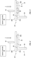
- FIG. 1 diagrammatically illustrates a first component panel 20, a second component panel 22, a stiffener component ("stiffener 24"), and an interface layer 26.
- the stiffener 24 is U-shaped and includes a web 28 extending between a first flange 30 and a second flange 32.
- the second component panel 22 is attached to the second flange 32 of the stiffener 24.
- the present disclosure will be described herein in the context of attaching (e.g., welding) the first component panel 20 to the first flange 30 of the stiffener 24.
- the interface layer 26 is disposed between the components to be joined; i.e., between the first component panel 20 and the first flange 30.
- the present disclosure is directed to a method and system for joining components that comprise one or more thermoplastic composite (TPC) materials.
- TPC thermoplastic composite
- Each of the components may comprise the same TPC material(s) or may comprise different TPC materials; e.g., a first component comprising a first TPC material, a second component comprising a second TPC material that is different from the first TPC material, and so on.
- a component may include a plurality layers of different TPC materials.
- thermoplastic materials that may be included within a TPC (e.g., as a matrix material or the like) include polyaryletherketone (PAEK), polyetheretherketone (PEEK), polyetherketoneketone (PEKK), polyetherimide (PEI), perfluoroalkopxy (PFA), polytetrafluoroethylene (PTFE), polyphenylene sulfide (PPS), and polyamide (PA - "nylon”), and variations thereof.
- PAEK polyaryletherketone
- PEEK polyetheretherketone
- PEKK polyetherketoneketone
- PEI polyetherimide
- PFA perfluoroalkopxy
- PTFE polytetrafluoroethylene
- PPS polyphenylene sulfide
- PA - "nylon" polyamide
- At least one of the components to be joined may be described as having a first region 34 contiguous with the bonding surface and a second region 36 contiguous with the outer surface (e.g., see FIG. 5 , showing a first component panel 20 having a first region 34 contiguous with the bonding surface 20A and a second region 36 contiguous with the outer surface 20B).
- the first and second regions 34, 36 may be configured to have different responses when subjected to the same or nearly the same amount of electromagnetic (EM) energy (e.g., an EM field).
- EM electromagnetic
- the first region 34 of the component may be described as having a first EM absorbing characteristic and the second region 36 of the component may be described as having a second EM absorbing characteristic, wherein the first region 34 may be configured to absorb EM energy faster than the second region 36 absorbs EM energy, or configured to absorb a greater amount of EM energy than the second region.
- first region 34 may be configured to absorb EM energy faster than the second region 36 absorbs EM energy, or configured to absorb a greater amount of EM energy than the second region.
- the first region 34 contiguous with the bonding surface 20A is configured to reach a melting temperature before the second region 36 contiguous with the outer surface 20B reaches its melting temperature when both are subjected to the same or nearly the same amount of EM energy; e.g., the first region 34 reaches its melting temperature in a period of time T1, and the second region 36 reaches its melting temperature in a period of time T2, and T1 is less than T2 (when both are subjected to the same or nearly the same amount of EM energy).
- the region of the component to be joined is configured to reach its melting temperature before the region of the component contiguous with the outer surface. It is our experience that the potential for surface deformation and/or component collapse increases as the component material approaches its melting temperature. Embodiments of the present disclosure facilitate the welding process and decrease the potential for surface deformation and/or component collapse.
- a component to be joined may include a first region 34 contiguous with the bonding surface 20A, a second region 36 contiguous with the outer surface 20B, and an isolation region 40 disposed between the first and second regions 34, 36.
- the component to be joined may have first and second regions 34, 36 that are configured to have substantially the same response when subjected to the same or nearly the same amount of EM energy (e.g., an EM field).
- the component to be joined may have first and second regions 34, 36 that are configured to have different responses when subjected to the same or nearly the same amount of EM energy (e.g., an EM field); i.e., as described above.
- the isolation region 40 may be configured to function as a thermally insulative region, or configured to function as an electrically insulative region, or both. In those embodiments wherein the isolation region 40 is configured to function as a thermally insulative region, the isolation region 40 is more thermally insulative than the first region 34, and may be more thermally insulative than both the first and second regions 34, 36. In those embodiments wherein the isolation region 40 is configured to function as an electrically insulative region, the isolation region 40 may be more electrically insulative than the first region 34, or the second region 36, or both.
- the interface layer 26 is typically configured to be present solely in the region between the components where the joining of the components is desired; i.e., the "bond region" (e.g., see dashed line 38 in FIG. 4 ).
- the interface layer 26 may be a single (i.e., unitary) body that is disposed throughout the bond region (e.g., see FIG. 2 ), or it may be a plurality of independent segments (e.g., strips) disposed within the bond region (e.g., see FIG. 3 ).
- the interface layer 26 (as a unitary body or collectively as a plurality of strips) may be configured to occupy all or substantially all of the bond region prior to the joining process.
- the interface layer 26 (as a unitary body or collectively as a plurality of strips) may be configured to occupy the all the bond region after the joining process.
- the interface layer 26 comprises at least one type of thermoplastic material.
- the interface layer 26 may have a homogenous configuration (e.g., the same thermoplastic material throughout), or it may include a fibrous material distributed within a thermoplastic material matrix (e.g., discontinuous fibers), or it may include a plurality of sublayers with different materials.
- a non-limiting example of an interface layer 26 with a plurality of sub-layers is one that includes a sub-layer comprising a mesh material, or a cloth material, or a screen material, or a layer of continuous fibers, or the like.
- the aforesaid fibrous material or sub-layer material may be electrically conductive, but is not required to be electrically conductive.
- Non-limiting examples of fiber material include ceramic, glass, metal, carbon, and the like.
- a non-limiting example of a screen material is one comprising a metallic material.
- the interface layer 26 does include an electrically conductive material (e.g., carbon fibers, carbon fiber mesh, metallic screen, and the like)
- the interaction of the EM field with the aforesaid electrically conductive material may expedite the production of a weld pool.
- the present disclosure utilizes an induction welding process that uses a source of electromagnetic (EM) energy (referred to hereinafter as an "inductor 42") to selectively subject the components to be joined to an EM field.
- EM electromagnetic
- the EM field interacting with the components 20, 26, 30 results in a thermal response within the components that elevates the temperature of the component portions to be joined.
- portions of the components melt to produce a "weld pool" of component material.
- the weld pool of material cools to a temperature below the melting temperature, the weld pool of material resolidifies and the components are joined; i.e., welded.
- the operating parameters of the inductor 42 may be controlled to produce an EM field that is appropriate for joining the particular thermoplastic composite components; i.e., different operating parameters may be used for different thermoplastic composite materials, component configurations, and the like.
- the inductor 42 may be configured to produce the requisite EM field throughout the bond region without relative movement between the components to be j oined and the inductor 42; i.e., the inductor 42 and components remain static.
- the present disclosure system may be configured to move the inductor 42 relative to the bond region to enable application of the EM field to all portions of the bond region, or the present disclosure system may be configured to move the components (and therefore the bond region) relative to the inductor 42 to enable application of the EM field to all portions of the bond region.
- the present disclosure is configured to apply a force to one of the components to be joined during the welding process.
- the present disclosure contemplates several different mechanisms (i.e., force actuators) for applying the force to the component (e.g., first component panel 20).
- force may be applied using a mechanical structure; e.g., a roller independent of the inductor 42.
- force may be applied using the inductor 42.
- the force may be applied as a point load (e.g., applied over a contact area relatively small in comparison to the area of bond region) or may be applied as a distributed load (e.g., applied uniformly over substantially all of the area of the bond region).
- the inductor 42 is diagrammatically shown as the force actuator, but the present disclosure is not limited thereto.
- prior art induction welding typically utilizes force applied to both sides of the components being joined to create a weld path and material collapse therein; e.g., a force applied to the outer surface 20B of the first component panel 20 and an opposing force applied to the side of the stiffener first flange 30 opposite the first flange bonding surface 30A.
- a blind weld there is often a greater chance of component collapse and/or excessive component deformation (e.g., resulting from excessive component melting) using prior art methods.
- the present disclosure is configured to produce the appropriate amount of thermal energy necessary to create a weld pool at the bond region, and less thermal energy in component regions adjacent to the bond region, as well as an application of force from one side of the components to be joined.
- the present disclosure is configured to use the inductor 42 to provide an EM field that produces the appropriate amount of thermal energy necessary to create a weld pool within a bond region (diagrammatically indicated by the dashed line 38) that includes a portion of the first component panel 20, the interface layer 26, and a portion of the first flange 30 of the stiffener 24.
- the air disposed in the separation gap 44 (between the first component panel 20 and the first flange 30) adjacent to the sides of the interface layer 26 is a poor conductor of thermal energy.
- the interface layer 26 is understood to act as a conduit of thermal energy with the first flange 30 of the stiffener 24.
- a region of the first flange 30 where bonding is desired i.e., aligned with the interface layer 26
- the interface layer 26 also facilitates intimate contact between the components 20, 26, 30.
- the present disclosure includes an application of force to the first component panel 20.
- the application of force to the first component panel 20 causes the melted interface layer 26 to collapse between the first component panel 20 and the first flange 30.
- the probability of intimate contact between the interface layer 26 and the first component panel 20 and between the interface layer 26 and the first flange 30 is increased. This aspect is particularly beneficial in those instances when component tolerances and/or surface irregularities may otherwise compromise the bonding process.
- a component to be joined includes a first region 34 and a second region 36 that are configured to have different responses when subjected to the same or nearly the same amount of EM energy (e.g., an EM field); e.g., a first region 34 contiguous with the bonding surface 20A that is configured to reach a melting temperature before a second region 36 contiguous with the outer surface 20B reaches its melting temperature when both are subjected to the same or nearly the same amount of EM energy.
- the creation of a weld pool in the bonding region may be facilitated by the faster melting first region 34.
- the relatively lesser response to the EM field by the second region 36 helps to prevent or mitigate the potential for deformation of the exposed outer surface 20B of the component 20.
- the combination of the interface layer 26 and the first region 34 of the first component panel 20 is understood to produce an improved bond between the components; e.g., the first component panel 20 and the first flange 30.
- a component to be joined (e.g., the first component panel 20 as shown in FIG. 6 ) includes a first region 34 (contiguous with the bonding surface 20A) and a second region 36 (contiguous with the outer surface 20B), separated from one another by an isolation region 40.
- the isolation region 40 may be configured to function as a thermally insulative region, or configured to function as an electrically insulative region, or both. In these embodiments, the creation of a weld pool in the bonding region may be facilitated by the isolation region 40.
- the isolation region 40 (configured to function as a thermally insulative region, or an electrically insulative region, or both) functions to separate the thermal responses of the first region 34 and the second region 36 to the EM field. In this manner, a greater thermal response in the first region 34 (e.g., faster melting than the second region 36) is separated from the thermal response in the second region 36.
- the isolated response to the EM field by the second region 36 may prevent or mitigate the potential for deformation of the exposed outer surface 20B of the component (e.g., first component panel 20).
- the isolation region 40 may be particularly beneficial in those instances wherein the first region 34 and the second region 36 are configured to have different responses when subjected to the same or nearly the same amount of EM energy (e.g., an EM field); e.g., the first region 34 configured to reach a melting temperature before the second region 36 when both are subjected to the same or nearly the same amount of EM energy.
- EM energy e.g., an EM field
- the present disclosure system may include the inductor 42 as detailed herein, a system controller 46, and sensors (e.g., pressure sensor, temperature sensor, and the like).
- the system may include a visual display device (not shown) configured to display information related to the bonding process as will be described herein.
- the system controller 46 is in communication with other components within the system, such as the inductor 42 and the sensors. In those embodiments that include a display device, the system controller 46 is also in communication with the display device. The system controller 46 may be in communication with these components to control and/or receive signals therefrom to perform the functions described herein.
- the system controller 46 may include any type of computing device, computational circuit, processor(s), CPU, computer, or the like capable of executing a series of instructions that are stored in memory.
- the instructions may include an operating system, and/or executable software modules such as program files, system data, buffers, drivers, utilities, and the like.
- the executable instructions may apply to any functionality described herein to enable the system to accomplish the same algorithmically and/or coordination of system components.
- the system controller 46 includes or is in communication with one or more memory devices.
- the present disclosure is not limited to any particular type of memory device, and the memory device may store instructions and/or data in a non-transitory manner. Examples of memory devices that may be used include read-only memory, random access memory, volatile memory, non-volatile memory, static memory, dynamic memory, flash memory, cache memory, and/or any device that stores digital information.
- the system controller may include, or may be in communication with, an input device that enables a user to enter data and/or instructions, and may include, or be in communication with, an output device configured, for example to display information (e.g., a visual display device as indicated above or a printer), or to transfer data, etc. Communications between the system controller 46 and other system components may be via a hardwire connection or via a wireless connection.
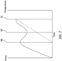
- FIG. 7 diagrammatically illustrates a graph of force (vertical axis) versus time (horizontal axis). Temperature is also indicated on a vertical axis.
- the graphed data indicates a welding process start point (e.g., at the graph origin). From the start of the welding process, the applied EM field causes an increase in temperature of at least portions of the first and second component and the interface layer 26. At the same time, the amount of force applied to the first component is increased.
- the graphed data further indicates a first inflection point 48 indicative of a starting point of plastic deformation associated with the welding process; e.g., plastic deformation of a portion of the first component panel 20, or a portion of the first flange 30 of the stiffener 24, or the interface layer 26, or some combination thereof.
- the graphed data further indicates a second inflection point 50 that indicates a minimum thickness of the interface layer 26 has been achieved.
- the interface layer 26 has melted and dispersed; e.g., the interface layer 26 is in intimate contact with the bonding surfaces of the first and second components; e.g., the bonding surfaces 20A, 30A of the first component panel 20 and the first flange 30 of the stiffener 24.
- the data curve portion between the first and second inflection points 48, 50 is representation of the interface layer 26 melting and dispersing between the first and second components as a result of the application of the EM field by the inductor 42 and the force applied to the first component panel 20.
- the graphed data indicates a third point inflection 52 point wherein the sensed force plateaus.
- the third inflection point 52 is indicative of the welding process being completed.
- the data represented in the graph may be used to control the welding process; e.g., the system may be configured to recognize the inflection points 48, 50, 52.
- the inductor 42 may be controlled to stop producing the EM field (or at least decreasing the EM field to a level wherein no further melting of the components occurs) and the components can be allowed to cool. In this manner, the welding process of a "blind weld" can be monitored to improve weld production and consistency.
- the graph shown in FIG. 7 is an example (e.g., a visual example) of how data can be used to monitor the welding process. The present disclosure does not require a visual implementation of process like that shown in FIG. 7 .
- any one of these structures may describe the operations as a sequential process, many of the operations can be performed in parallel or concurrently.
- the order of the operations may be rearranged.
- a process may correspond to a method, a function, a procedure, a subroutine, a subprogram, etc.
Landscapes
- Engineering & Computer Science (AREA)
- Mechanical Engineering (AREA)
- Physics & Mathematics (AREA)
- Thermal Sciences (AREA)
- Health & Medical Sciences (AREA)
- Electromagnetism (AREA)
- Toxicology (AREA)
- Textile Engineering (AREA)
- Lining Or Joining Of Plastics Or The Like (AREA)
Abstract
Description
- The present disclosure relates to methods and apparatus for joining thermoplastic composite components together in general, and to methods and apparatus for welding thermoplastic composite components in particular.
- Current techniques for welding thermoplastic composite components typically utilize force applied to opposite sides of the components being joined to create a weld path and material collapse therein. In many instances, it is not possible to apply opposing force to the components to be joined - a scenario sometimes referred to as a "blind weld". In these instances, controlling the weld pool can be difficult and the probability of component collapse and/or excessive component deformation is increased. What is needed is a method and/or system that can be used to facilitate blind welds.
- According to an aspect of the present disclosure, a method of blind welding thermoplastic composite components is provided that includes the following: providing a first thermoplastic composite (FTPC) component having a thickness that extends between an outer surface and an opposite FTPC bonding surface; providing a second thermoplastic composite (STPC) component having a STPC bonding surface; providing an interface layer comprising a thermoplastic material; disposing the interface layer between the FTPC bonding surface and the STPC bonding surface, such that the FTPC bonding surface is contiguous with the interface layer, and the STPC bonding surface is contiguous with the interface layer; applying a normal force to the outer surface of the first thermoplastic composite component without an application of an opposing second normal force to the second thermoplastic component; applying an electromagnetic field to at least portions of the first thermoplastic composite component, the second thermoplastic composite component, and the interface layer while the normal force is applied, and maintaining the application of the electromagnetic field until the at least portions of the first thermoplastic composite component, the second thermoplastic composite component, and the interface layer create a weld pool; and removing the application of the electromagnetic field after the weld pool is created.
- In any of the aspects or embodiments described above and herein, the interface layer may be a unitary body configured to occupy substantially all of a bond region between the first thermoplastic composite and the second thermoplastic composite.
- In any of the aspects or embodiments described above and herein, the interface layer may occupy substantially all of the bond region between the first thermoplastic composite and the second thermoplastic composite subsequent to the weld pool creation.
- In any of the aspects or embodiments described above and herein, the thermoplastic material of the interface layer may be homogenous.
- In any of the aspects or embodiments described above and herein, the interface layer may include a fibrous material distributed in a matrix of said thermoplastic material.
- In any of the aspects or embodiments described above and herein, the interface layer may include an electrically conductive material.
- In any of the aspects or embodiments described above and herein, the interface layer may comprise a plurality of independent segments configured to collectively occupy substantially all of a bond region between the first thermoplastic composite and the second thermoplastic composite.
- In any of the aspects or embodiments described above and herein, the first thermoplastic composite component may include a first region contiguous with the bonding surface and a second region contiguous with the outer surface, and the first region may be configured to have a first response when subjected to the electromagnetic field, and the second region may be configured to have a second response when subjected to the electromagnetic field, and the first response may be different from the second response.
- In any of the aspects or embodiments described above and herein, the first response may include reaching a melting temperature of the first region in a period of time T1, and the second response may include reaching a melting temperature of the second region in a period of time T2, and T1 may be less than T2.
- In any of the aspects or embodiments described above and herein, the first thermoplastic composite component may include a first region contiguous with the bonding surface, a second region contiguous with the outer surface, and an isolation region disposed between the first region and the second region, and the isolation region may be configured to be more thermally insulative than the first region.
- In any of the aspects or embodiments described above and herein, the isolation region may be configured to be more thermally insulative than both the first region and the second region.
- In any of the aspects or embodiments described above and herein, the first region (FR) may be configured to reach an FR melting temperature in a period of time T1, and the second region (SR) may be configured to reach a SR melting temperature in a period of time T2, and T1 may be less than T2.
- In any of the aspects or embodiments described above and herein, the first thermoplastic composite component may include a first region contiguous with the bonding surface, a second region contiguous with the outer surface, and an isolation region disposed between the first region and the second region, and the isolation region may be configured to be more electrically insulative than the first region, or the second region, or both.
- According to an aspect of the present disclosure a process of welding a first thermoplastic composite component to a second thermoplastic composite component is provided. The first thermoplastic composite (FTPC) component has a thickness that extends between an outer surface and an opposite FTPC bonding surface, and the second thermoplastic composite (STPC) component has a STPC bonding surface. An interface layer is disposed between the FTPC bonding surface and the STPC bonding surface. The method includes: applying a normal force to the outer surface of the first thermoplastic composite component without an application of an opposing second normal force to the second thermoplastic component; applying an electromagnetic field to at least portions of the first thermoplastic composite component, the second thermoplastic composite component, and the interface layer while the normal force is applied, the applied electromagnetic field configured to create a weld pool; determining a first inflection point of the applied normal force, a second inflection point of the applied normal force, wherein the applied normal force decreases between the first inflection point and the second inflection point, and a third inflection point whereafter the applied normal force becomes substantially constant; and removing the applied electromagnetic field to permit the weld pool to solidify upon determining the third inflection point.
- According to an aspect of the present disclosure, a system for welding a first thermoplastic composite component to a second thermoplastic composite component is provided. The first thermoplastic composite (FTPC) component has a thickness that extends between an outer surface and an opposite FTPC bonding surface, and the second thermoplastic composite (STPC) component has a STPC bonding surface. An interface layer is disposed between the FTPC bonding surface and the STPC bonding surface. The system includes a force actuator, an electromagnetic inductor, and a system controller. The force actuator is configured to apply a normal force to the outer surface of the first thermoplastic composite component without an application of an opposing second normal force to the second thermoplastic component. The electromagnetic inductor is configured to selectively produce an electromagnetic field sufficiently to melt at least portions of the first thermoplastic composite component, the second thermoplastic composite component, and the interface layer. The system controller is in communication with the force actuator, the electromagnetic inductor, and a non-transitory memory storing instructions. The instructions when executed cause the system controller to: control the force actuator to apply a normal force to the outer surface of the first thermoplastic composite component without an application of an opposing second normal force to the second thermoplastic component; control the electromagnetic inductor to apply an electromagnetic field to at least portions of the first thermoplastic composite component, the second thermoplastic composite component, and the interface layer while the normal force is applied, the applied electromagnetic field configured to create a weld pool; determine a first inflection point of the applied normal force, a second inflection point of the applied normal force, wherein the applied normal force decreases between the first inflection point and the second inflection point, and a third inflection point whereafter the applied normal force becomes substantially constant; and control the electromagnetic conductor to remove the applied electromagnetic field to permit the weld pool to solidify upon determining the third inflection point.
- The foregoing features and elements may be combined in various combinations without exclusivity, unless expressly indicated otherwise. For example, aspects and/or embodiments of the present disclosure may include any one or more of the individual features or elements disclosed above and/or below alone or in any combination thereof. These features and elements as well as the operation thereof will become more apparent in light of the following description and the accompanying drawings. It should be understood, however, the following description and drawings are intended to be exemplary in nature and non-limiting.
-
-
FIG. 1 is a diagrammatic view of thermoplastic components. -
FIG. 2 is a diagrammatic view of thermoplastic components to be joined, illustrating an embodiment of the present disclosure. -
FIG. 3 is a diagrammatic view of thermoplastic components to be joined, illustrating an embodiment of the present disclosure. -
FIG. 4 is a diagrammatic view of thermoplastic components to be joined, illustrating an embodiment of the present disclosure. -
FIG. 5 is a diagrammatic view of thermoplastic components to be joined, illustrating an embodiment of the present disclosure. -
FIG. 6 is a diagrammatic view of thermoplastic components to be joined, illustrating an embodiment of the present disclosure. -
FIG. 7 is a graph of force versus time, diagrammatically illustrating present disclosure welding process data. -
FIG. 1 diagrammatically illustrates afirst component panel 20, asecond component panel 22, a stiffener component ("stiffener 24"), and aninterface layer 26. Thestiffener 24 is U-shaped and includes aweb 28 extending between afirst flange 30 and asecond flange 32. Thesecond component panel 22 is attached to thesecond flange 32 of thestiffener 24. The present disclosure will be described herein in the context of attaching (e.g., welding) thefirst component panel 20 to thefirst flange 30 of thestiffener 24. Theinterface layer 26 is disposed between the components to be joined; i.e., between thefirst component panel 20 and thefirst flange 30. The respective surfaces of thefirst component panel 20 and thefirst flange 30 contiguous with theinterface layer 26 may be referred to herein as thebonding surfaces first component panel 20 includes anouter surface 20B opposite thebonding surface 20A and a thickness that extends therebetween. Thecomponents FIG. 1 are provided to illustrate an example of the present disclosure and the present disclosure is not limited to joining components like those shown inFIG. 1 .FIGS. 2-4 diagrammatically illustrate a portion of thefirst component panel 20 and the stiffenerfirst flange 30 where the two are to be joined together in various different embodiments. The present disclosure provides considerable utility in the production of aircraft components such as, but not limited to, fins, control surfaces, stabilizers, and the like. - The present disclosure is directed to a method and system for joining components that comprise one or more thermoplastic composite (TPC) materials. Each of the components may comprise the same TPC material(s) or may comprise different TPC materials; e.g., a first component comprising a first TPC material, a second component comprising a second TPC material that is different from the first TPC material, and so on. As will be detailed herein, in some embodiments, a component may include a plurality layers of different TPC materials. Non-limiting examples of thermoplastic materials that may be included within a TPC (e.g., as a matrix material or the like) include polyaryletherketone (PAEK), polyetheretherketone (PEEK), polyetherketoneketone (PEKK), polyetherimide (PEI), perfluoroalkopxy (PFA), polytetrafluoroethylene (PTFE), polyphenylene sulfide (PPS), and polyamide (PA - "nylon"), and variations thereof.
- In some embodiments, at least one of the components to be joined may be described as having a
first region 34 contiguous with the bonding surface and asecond region 36 contiguous with the outer surface (e.g., seeFIG. 5 , showing afirst component panel 20 having afirst region 34 contiguous with thebonding surface 20A and asecond region 36 contiguous with theouter surface 20B). The first andsecond regions first region 34 of the component may be described as having a first EM absorbing characteristic and thesecond region 36 of the component may be described as having a second EM absorbing characteristic, wherein thefirst region 34 may be configured to absorb EM energy faster than thesecond region 36 absorbs EM energy, or configured to absorb a greater amount of EM energy than the second region. For example and again referring toFIG. 5 , thefirst region 34 contiguous with thebonding surface 20A is configured to reach a melting temperature before thesecond region 36 contiguous with theouter surface 20B reaches its melting temperature when both are subjected to the same or nearly the same amount of EM energy; e.g., thefirst region 34 reaches its melting temperature in a period of time T1, and thesecond region 36 reaches its melting temperature in a period of time T2, and T1 is less than T2 (when both are subjected to the same or nearly the same amount of EM energy). In this manner, the region of the component to be joined is configured to reach its melting temperature before the region of the component contiguous with the outer surface. It is our experience that the potential for surface deformation and/or component collapse increases as the component material approaches its melting temperature. Embodiments of the present disclosure facilitate the welding process and decrease the potential for surface deformation and/or component collapse. - Referring to
FIG. 6 , in some embodiments a component to be joined (e.g., first component panel 20) may include afirst region 34 contiguous with thebonding surface 20A, asecond region 36 contiguous with theouter surface 20B, and anisolation region 40 disposed between the first andsecond regions second regions second regions isolation region 40 may be configured to function as a thermally insulative region, or configured to function as an electrically insulative region, or both. In those embodiments wherein theisolation region 40 is configured to function as a thermally insulative region, theisolation region 40 is more thermally insulative than thefirst region 34, and may be more thermally insulative than both the first andsecond regions isolation region 40 is configured to function as an electrically insulative region, theisolation region 40 may be more electrically insulative than thefirst region 34, or thesecond region 36, or both. - The
interface layer 26 is typically configured to be present solely in the region between the components where the joining of the components is desired; i.e., the "bond region" (e.g., see dashedline 38 inFIG. 4 ). Theinterface layer 26 may be a single (i.e., unitary) body that is disposed throughout the bond region (e.g., seeFIG. 2 ), or it may be a plurality of independent segments (e.g., strips) disposed within the bond region (e.g., seeFIG. 3 ). In some embodiments, the interface layer 26 (as a unitary body or collectively as a plurality of strips) may be configured to occupy all or substantially all of the bond region prior to the joining process. In some embodiments, the interface layer 26 (as a unitary body or collectively as a plurality of strips) may be configured to occupy the all the bond region after the joining process. Theinterface layer 26 comprises at least one type of thermoplastic material. Theinterface layer 26 may have a homogenous configuration (e.g., the same thermoplastic material throughout), or it may include a fibrous material distributed within a thermoplastic material matrix (e.g., discontinuous fibers), or it may include a plurality of sublayers with different materials. A non-limiting example of aninterface layer 26 with a plurality of sub-layers is one that includes a sub-layer comprising a mesh material, or a cloth material, or a screen material, or a layer of continuous fibers, or the like. The aforesaid fibrous material or sub-layer material may be electrically conductive, but is not required to be electrically conductive. Non-limiting examples of fiber material include ceramic, glass, metal, carbon, and the like. A non-limiting example of a screen material is one comprising a metallic material. In those embodiments wherein theinterface layer 26 does include an electrically conductive material (e.g., carbon fibers, carbon fiber mesh, metallic screen, and the like), the interaction of the EM field with the aforesaid electrically conductive material may expedite the production of a weld pool. - The present disclosure utilizes an induction welding process that uses a source of electromagnetic (EM) energy (referred to hereinafter as an "
inductor 42") to selectively subject the components to be joined to an EM field. The EM field interacting with thecomponents inductor 42 may be configured to produce the requisite EM field throughout the bond region without relative movement between the components to be j oined and theinductor 42; i.e., theinductor 42 and components remain static. In other embodiments, the present disclosure system may be configured to move theinductor 42 relative to the bond region to enable application of the EM field to all portions of the bond region, or the present disclosure system may be configured to move the components (and therefore the bond region) relative to theinductor 42 to enable application of the EM field to all portions of the bond region. - The present disclosure is configured to apply a force to one of the components to be joined during the welding process. The present disclosure contemplates several different mechanisms (i.e., force actuators) for applying the force to the component (e.g., first component panel 20). For example, in some embodiments force may be applied using a mechanical structure; e.g., a roller independent of the
inductor 42. As another example, force may be applied using theinductor 42. The force may be applied as a point load (e.g., applied over a contact area relatively small in comparison to the area of bond region) or may be applied as a distributed load (e.g., applied uniformly over substantially all of the area of the bond region). In the FIGURES, theinductor 42 is diagrammatically shown as the force actuator, but the present disclosure is not limited thereto. - As stated above, prior art induction welding typically utilizes force applied to both sides of the components being joined to create a weld path and material collapse therein; e.g., a force applied to the
outer surface 20B of thefirst component panel 20 and an opposing force applied to the side of the stiffenerfirst flange 30 opposite the firstflange bonding surface 30A. In those instances where it is not possible to apply force to both sides of the components to be joined (a "blind weld") there is often a greater chance of component collapse and/or excessive component deformation (e.g., resulting from excessive component melting) using prior art methods. - The present disclosure is configured to produce the appropriate amount of thermal energy necessary to create a weld pool at the bond region, and less thermal energy in component regions adjacent to the bond region, as well as an application of force from one side of the components to be joined. Using the components shown in
FIG. 4 as a specific example, the present disclosure is configured to use theinductor 42 to provide an EM field that produces the appropriate amount of thermal energy necessary to create a weld pool within a bond region (diagrammatically indicated by the dashed line 38) that includes a portion of thefirst component panel 20, theinterface layer 26, and a portion of thefirst flange 30 of thestiffener 24. The air disposed in the separation gap 44 (between thefirst component panel 20 and the first flange 30) adjacent to the sides of theinterface layer 26 is a poor conductor of thermal energy. Theinterface layer 26, in contrast, increases in temperature as a result of the EM field application. Hence, theinterface layer 26 is understood to act as a conduit of thermal energy with thefirst flange 30 of thestiffener 24. In this manner, a region of thefirst flange 30 where bonding is desired (i.e., aligned with the interface layer 26) is understood to reach the requisite melting temperature faster than adjacent regions of thefirst flange 30, thereby reducing the chance of component collapse and/or excessive component deformation. In addition to the beneficial thermal path associated with theinterface layer 26, theinterface layer 26 also facilitates intimate contact between thecomponents first component panel 20. During the bonding process, the application of force to thefirst component panel 20 causes the meltedinterface layer 26 to collapse between thefirst component panel 20 and thefirst flange 30. As a result, the probability of intimate contact between theinterface layer 26 and thefirst component panel 20 and between theinterface layer 26 and thefirst flange 30 is increased. This aspect is particularly beneficial in those instances when component tolerances and/or surface irregularities may otherwise compromise the bonding process. - As stated above, in some embodiments a component to be joined (e.g., the
first component panel 20 as shown inFIG. 5 ) includes afirst region 34 and asecond region 36 that are configured to have different responses when subjected to the same or nearly the same amount of EM energy (e.g., an EM field); e.g., afirst region 34 contiguous with thebonding surface 20A that is configured to reach a melting temperature before asecond region 36 contiguous with theouter surface 20B reaches its melting temperature when both are subjected to the same or nearly the same amount of EM energy. In these embodiments, the creation of a weld pool in the bonding region may be facilitated by the faster meltingfirst region 34. At the same time, the relatively lesser response to the EM field by thesecond region 36 helps to prevent or mitigate the potential for deformation of the exposedouter surface 20B of thecomponent 20. The combination of theinterface layer 26 and thefirst region 34 of thefirst component panel 20 is understood to produce an improved bond between the components; e.g., thefirst component panel 20 and thefirst flange 30. - As stated above, in some embodiments a component to be joined (e.g., the
first component panel 20 as shown inFIG. 6 ) includes a first region 34 (contiguous with thebonding surface 20A) and a second region 36 (contiguous with theouter surface 20B), separated from one another by anisolation region 40. Theisolation region 40 may be configured to function as a thermally insulative region, or configured to function as an electrically insulative region, or both. In these embodiments, the creation of a weld pool in the bonding region may be facilitated by theisolation region 40. The isolation region 40 (configured to function as a thermally insulative region, or an electrically insulative region, or both) functions to separate the thermal responses of thefirst region 34 and thesecond region 36 to the EM field. In this manner, a greater thermal response in the first region 34 (e.g., faster melting than the second region 36) is separated from the thermal response in thesecond region 36. The isolated response to the EM field by thesecond region 36 may prevent or mitigate the potential for deformation of the exposedouter surface 20B of the component (e.g., first component panel 20). Theisolation region 40 may be particularly beneficial in those instances wherein thefirst region 34 and thesecond region 36 are configured to have different responses when subjected to the same or nearly the same amount of EM energy (e.g., an EM field); e.g., thefirst region 34 configured to reach a melting temperature before thesecond region 36 when both are subjected to the same or nearly the same amount of EM energy. - According to an aspect of the present disclosure, a method of monitoring the welding process between the components (e.g.,
first component panel 20 and stiffener first flange 30) is provided. In these embodiments, the present disclosure system may include theinductor 42 as detailed herein, asystem controller 46, and sensors (e.g., pressure sensor, temperature sensor, and the like). In some embodiments, the system may include a visual display device (not shown) configured to display information related to the bonding process as will be described herein. - The
system controller 46 is in communication with other components within the system, such as theinductor 42 and the sensors. In those embodiments that include a display device, thesystem controller 46 is also in communication with the display device. Thesystem controller 46 may be in communication with these components to control and/or receive signals therefrom to perform the functions described herein. Thesystem controller 46 may include any type of computing device, computational circuit, processor(s), CPU, computer, or the like capable of executing a series of instructions that are stored in memory. The instructions may include an operating system, and/or executable software modules such as program files, system data, buffers, drivers, utilities, and the like. The executable instructions may apply to any functionality described herein to enable the system to accomplish the same algorithmically and/or coordination of system components. Thesystem controller 46 includes or is in communication with one or more memory devices. The present disclosure is not limited to any particular type of memory device, and the memory device may store instructions and/or data in a non-transitory manner. Examples of memory devices that may be used include read-only memory, random access memory, volatile memory, non-volatile memory, static memory, dynamic memory, flash memory, cache memory, and/or any device that stores digital information. The system controller may include, or may be in communication with, an input device that enables a user to enter data and/or instructions, and may include, or be in communication with, an output device configured, for example to display information (e.g., a visual display device as indicated above or a printer), or to transfer data, etc. Communications between thesystem controller 46 and other system components may be via a hardwire connection or via a wireless connection. -
FIG. 7 diagrammatically illustrates a graph of force (vertical axis) versus time (horizontal axis). Temperature is also indicated on a vertical axis. The graphed data indicates a welding process start point (e.g., at the graph origin). From the start of the welding process, the applied EM field causes an increase in temperature of at least portions of the first and second component and theinterface layer 26. At the same time, the amount of force applied to the first component is increased. The graphed data further indicates afirst inflection point 48 indicative of a starting point of plastic deformation associated with the welding process; e.g., plastic deformation of a portion of thefirst component panel 20, or a portion of thefirst flange 30 of thestiffener 24, or theinterface layer 26, or some combination thereof. The graphed data further indicates asecond inflection point 50 that indicates a minimum thickness of theinterface layer 26 has been achieved. At thesecond inflection point 50, theinterface layer 26 has melted and dispersed; e.g., theinterface layer 26 is in intimate contact with the bonding surfaces of the first and second components; e.g., the bonding surfaces 20A, 30A of thefirst component panel 20 and thefirst flange 30 of thestiffener 24. The data curve portion between the first andsecond inflection points interface layer 26 melting and dispersing between the first and second components as a result of the application of the EM field by theinductor 42 and the force applied to thefirst component panel 20. The graphed data indicates athird point inflection 52 point wherein the sensed force plateaus. Thethird inflection point 52 is indicative of the welding process being completed. In some present disclosure embodiments, the data represented in the graph may be used to control the welding process; e.g., the system may be configured to recognize theinflection points inductor 42 may be controlled to stop producing the EM field (or at least decreasing the EM field to a level wherein no further melting of the components occurs) and the components can be allowed to cool. In this manner, the welding process of a "blind weld" can be monitored to improve weld production and consistency. The graph shown inFIG. 7 is an example (e.g., a visual example) of how data can be used to monitor the welding process. The present disclosure does not require a visual implementation of process like that shown inFIG. 7 . - While the principles of the disclosure have been described above in connection with specific apparatuses and methods, it is to be clearly understood that this description is made only by way of example and not as limitation on the scope of the disclosure. Specific details are given in the above description to provide a thorough understanding of the embodiments. However, it is understood that the embodiments may be practiced without these specific details.
- It is noted that the embodiments may be described as a process which is depicted as a flowchart, a flow diagram, a block diagram, etc. Although any one of these structures may describe the operations as a sequential process, many of the operations can be performed in parallel or concurrently. In addition, the order of the operations may be rearranged. A process may correspond to a method, a function, a procedure, a subroutine, a subprogram, etc.
- The singular forms "a," "an," and "the" refer to one or more than one, unless the context clearly dictates otherwise. For example, the term "comprising a specimen" includes single or plural specimens and is considered equivalent to the phrase "comprising at least one specimen." The term "or" refers to a single element of stated alternative elements or a combination of two or more elements unless the context clearly indicates otherwise. As used herein, "comprises" means "includes." Thus, "comprising A or B," means "including A or B, or A and B," without excluding additional elements.
- It is noted that various connections are set forth between elements in the present description and drawings (the contents of which are included in this disclosure by way of reference). It is noted that these connections are general and, unless specified otherwise, may be direct or indirect and that this specification is not intended to be limiting in this respect. Any reference to attached, fixed, connected or the like may include permanent, removable, temporary, partial, full and/or any other possible attachment option.
- No element, component, or method step in the present disclosure is intended to be dedicated to the public regardless of whether the element, component, or method step is explicitly recited in the claim. As used herein, the terms "comprise", "comprising", or any other variation thereof, are intended to cover a non-exclusive inclusion, such that a process, method, article, or apparatus that comprises a list of elements does not include only those elements but may include other elements not expressly listed or inherent to such process, method, article, or apparatus.
- While various inventive aspects, concepts and features of the disclosures may be described and illustrated herein as embodied in combination in the exemplary embodiments, these various aspects, concepts, and features may be used in many alternative embodiments, either individually or in various combinations and sub-combinations thereof. Unless expressly excluded herein all such combinations and sub-combinations are intended to be within the scope of the present application. Still further, while various alternative embodiments as to the various aspects, concepts, and features of the disclosures--such as alternative materials, structures, configurations, methods, devices, and components, and so on--may be described herein, such descriptions are not intended to be a complete or exhaustive list of available alternative embodiments, whether presently known or later developed. Those skilled in the art may readily adopt one or more of the inventive aspects, concepts, or features into additional embodiments and uses within the scope of the present application even if such embodiments are not expressly disclosed herein. For example, in the exemplary embodiments described above within the Detailed Description portion of the present specification, elements may be described as individual units and shown as independent of one another to facilitate the description. In alternative embodiments, such elements may be configured as combined elements. It is further noted that various method or process steps for embodiments of the present disclosure are described herein. The description may present method and/or process steps as a particular sequence. However, to the extent that the method or process does not rely on the particular order of steps set forth herein, the method or process should not be limited to the particular sequence of steps described. As one of ordinary skill in the art would appreciate, other sequences of steps may be possible. Therefore, the particular order of the steps set forth in the description should not be construed as a limitation.
Claims (15)
- A method of blind welding thermoplastic composite components, comprising:providing a first thermoplastic composite (FTPC) component (20) having a thickness that extends between an outer surface (20B) and an opposite FTPC bonding surface (20A);providing a second thermoplastic composite (STPC) component (24) having a STPC bonding surface (30A);providing an interface layer (26) comprising a thermoplastic material;disposing the interface layer (26) between the FTPC bonding surface (20A) and the STPC bonding surface (30A), such that the FTPC bonding surface (20A) is contiguous with the interface layer (26), and the STPC bonding surface (30A) is contiguous with the interface layer (26);applying a normal force to the outer surface (20B) of the first thermoplastic composite component (20) without an application of an opposing second normal force to the second thermoplastic component (24);applying an electromagnetic field to at least portions of the first thermoplastic composite component (20), the second thermoplastic composite component (24), and the interface layer (26) while the normal force is applied, and maintaining the application of the electromagnetic field until the at least portions of the first thermoplastic composite component (20), the second thermoplastic composite component (24), and the interface layer (26) create a weld pool; andremoving the application of the electromagnetic field after the weld pool is created.
- The method of claim 1, wherein the interface layer (26) is a unitary body configured to occupy substantially all of a bond region (38) between the first thermoplastic composite component (20) and the second thermoplastic composite component (24).
- The method of claim 2, wherein the interface layer (26) occupies substantially all of the bond region (38) between the first thermoplastic composite component (20) and the second thermoplastic composite component (24) subsequent to the weld pool creation.
- The method of claim 1, 2 or 3, wherein the thermoplastic material of the interface layer (26) is homogenous.
- The method of any preceding claim, wherein the interface layer (26) includes a fibrous material distributed in a matrix of said thermoplastic material.
- The method of any preceding claim, wherein the interface layer (26) includes an electrically conductive material.
- The method of any preceding claim, wherein the interface layer (26) comprises a plurality of independent segments configured to collectively occupy substantially all of a bond region (38) between the first thermoplastic composite component (20) and the second thermoplastic composite component (24).
- A method of welding a first thermoplastic composite component (20) to a second thermoplastic composite component (24), wherein the first thermoplastic composite (FTPC) component (20) has a thickness that extends between an outer surface (20B) and an opposite FTPC bonding surface (20A), and the second thermoplastic composite (STPC) component (24) has a STPC bonding surface (30A), wherein an interface layer (26) is disposed between the FTPC bonding surface (20A) and the STPC bonding surface (30A), the method comprising:applying a normal force to the outer surface (20B) of the first thermoplastic composite component (20) without an application of an opposing second normal force to the second thermoplastic component (24);applying an electromagnetic field to at least portions of the first thermoplastic composite component (20), the second thermoplastic composite component (24), and the interface layer (26) while the normal force is applied, the applied electromagnetic field configured to create a weld pool;determining a first inflection point (48) of the applied normal force, a second inflection point (50) of the applied normal force, wherein the applied normal force decreases between the first inflection point (48) and the second inflection point (50), and a third inflection point (52) whereafter the applied normal force becomes substantially constant; andremoving the applied electromagnetic field to permit the weld pool to solidify upon determining the third inflection point (52).
- The method of any preceding claim, wherein the first thermoplastic composite component (20) includes a first region (34) contiguous with the bonding surface (20A) and a second region (36) contiguous with the outer surface (20B);
wherein the first region (34) is configured to have a first response when subjected to the electromagnetic field, and the second region (36) is configured to have a second response when subjected to the electromagnetic field, and the first response is different from the second response. - The method of claim 9, wherein the first response includes reaching a melting temperature of the first region (34) in a period of time T1, and the second response includes reaching a melting temperature of the second region (36) in a period of time T2, and T1 is less than T2.
- The method of any preceding claim, wherein the first thermoplastic composite component (20) includes a first region (34) contiguous with the bonding surface (20A), a second region (36) contiguous with the outer surface (20B), and an isolation region (40) disposed between the first region (34) and the second region (36);
wherein the isolation region (40) is configured to be more thermally insulative than the first region (34). - The method of claim 11, wherein the isolation region (40) is configured to be more thermally insulative than both the first region (34) and the second region (36).
- The method of claim 11 or 12, wherein the first region (FR) (34) is configured to reach an FR melting temperature in a period of time T1, and the second region (SR) (36) is configured to reach a SR melting temperature in a period of time T2, and T1 is less than T2.
- The method of any preceding claim, wherein the first thermoplastic composite component (20) includes a first region (34) contiguous with the bonding surface (20A), a second region (36) contiguous with the outer surface (20B), and an isolation region (40) disposed between the first region (34) and the second region (36);
wherein the isolation region (40) is configured to be more electrically insulative than the first region (34), or the second region (36), or both. - A system for welding a first thermoplastic composite component (20) to a second thermoplastic composite component (24), wherein the first thermoplastic composite (FTPC) component (20) has a thickness that extends between an outer surface (20B) and an opposite FTPC bonding surface (20A), and the second thermoplastic composite (STPC) component (24) has a STPC bonding surface (30A), wherein an interface layer (26) is disposed between the FTPC bonding surface (20A) and the STPC bonding surface (30A), the system comprising:a force actuator configured to apply a normal force to the outer surface (20B) of the first thermoplastic composite component (20) without an application of an opposing second normal force to the second thermoplastic component (24);an electromagnetic inductor (42) configured to selectively produce an electromagnetic field sufficiently to melt at least portions of the first thermoplastic composite component (20), the second thermoplastic composite component (24), and the interface layer (26); anda system controller (46) in communication with the force actuator, the electromagnetic inductor (42), and a non-transitory memory storing instructions, which instructions when executed cause the system controller (46) to:control the force actuator to apply a normal force to the outer surface (20B) of the first thermoplastic composite component (20) without an application of an opposing second normal force to the second thermoplastic component (24);control the electromagnetic inductor (42) to apply an electromagnetic field to at least portions of the first thermoplastic composite component (20), the second thermoplastic composite component (24), and the interface layer (26) while the normal force is applied, the applied electromagnetic field configured to create a weld pool;determine a first inflection point (48) of the applied normal force, a second inflection point (50) of the applied normal force, wherein the applied normal force decreases between the first inflection point (48) and the second inflection point (50), and a third inflection point (52) whereafter the applied normal force becomes substantially constant; andcontrol the electromagnetic conductor to remove the applied electromagnetic field to permit the weld pool to solidify upon determining the third inflection point (52).
Applications Claiming Priority (1)
| Application Number | Priority Date | Filing Date | Title |
|---|---|---|---|
| US18/224,974 US20250026083A1 (en) | 2023-07-21 | 2023-07-21 | Method and apparatus for joining thermoplastic composite components |
Publications (1)
| Publication Number | Publication Date |
|---|---|
| EP4494852A1 true EP4494852A1 (en) | 2025-01-22 |
Family
ID=91961886
Family Applications (1)
| Application Number | Title | Priority Date | Filing Date |
|---|---|---|---|
| EP24189798.2A Pending EP4494852A1 (en) | 2023-07-21 | 2024-07-19 | Method and system for joining thermoplastic composite components |
Country Status (2)
| Country | Link |
|---|---|
| US (1) | US20250026083A1 (en) |
| EP (1) | EP4494852A1 (en) |
Families Citing this family (1)
| Publication number | Priority date | Publication date | Assignee | Title |
|---|---|---|---|---|
| US12485624B2 (en) * | 2023-07-21 | 2025-12-02 | Rohr, Inc. | Method and apparatus for joining thermoplastic composite components |
Citations (3)
| Publication number | Priority date | Publication date | Assignee | Title |
|---|---|---|---|---|
| US3900360A (en) * | 1972-10-20 | 1975-08-19 | Heller William C Jun | Self-heating composite bonding means and method |
| US5444220A (en) * | 1991-10-18 | 1995-08-22 | The Boeing Company | Asymmetric induction work coil for thermoplastic welding |
| US20200214090A1 (en) * | 2016-08-18 | 2020-07-02 | University Of South Carolina | Printable Susceptor for Use in Induction Welding |
-
2023
- 2023-07-21 US US18/224,974 patent/US20250026083A1/en active Pending
-
2024
- 2024-07-19 EP EP24189798.2A patent/EP4494852A1/en active Pending
Patent Citations (3)
| Publication number | Priority date | Publication date | Assignee | Title |
|---|---|---|---|---|
| US3900360A (en) * | 1972-10-20 | 1975-08-19 | Heller William C Jun | Self-heating composite bonding means and method |
| US5444220A (en) * | 1991-10-18 | 1995-08-22 | The Boeing Company | Asymmetric induction work coil for thermoplastic welding |
| US20200214090A1 (en) * | 2016-08-18 | 2020-07-02 | University Of South Carolina | Printable Susceptor for Use in Induction Welding |
Also Published As
| Publication number | Publication date |
|---|---|
| US20250026083A1 (en) | 2025-01-23 |
Similar Documents
| Publication | Publication Date | Title |
|---|---|---|
| US20250026083A1 (en) | Method and apparatus for joining thermoplastic composite components | |
| US4421582A (en) | Self-heating article with deformable electrodes | |
| US5705796A (en) | Reinforced composites formed using induction thermoplastic welding | |
| EP4215349A1 (en) | Resistance repair of thermoplastic components | |
| CN105358281B (en) | The contact of electrochromic device | |
| EP3461620B1 (en) | Method for the resistance welding of fibre-composite components to give a fibre-composite structure, fibre-composite structure and fibre-composite component | |
| US7853165B2 (en) | Apparatus and method for a multi-tap series resistance heating element in a belt fuser | |
| JP2005536583A (en) | How to accelerate joint hardening | |
| US20160288241A1 (en) | Multi-stage resistance welding of sandwich-type metal sheets | |
| EP4494851A1 (en) | Method for joining thermoplastic composite components | |
| DE69308208T2 (en) | HEATING DEVICE FOR THERMOPLASTIC WELDING | |
| Choudhury et al. | Improving the mechanical performance of resistance-welded green composite joints using different heating elements | |
| CN112776379A (en) | Assembly and method for repairing thermoplastic composites | |
| US20190091939A1 (en) | Method for bonding composite materials together | |
| CA2946022A1 (en) | Method and apparatus for welding together a first object and a second object | |
| EP2662198B1 (en) | Method for creating an overlap by sheet welding | |
| CN110014660B (en) | Method for manufacturing a carrier component, carrier component and carrier having the carrier component | |
| US10160057B2 (en) | Method and device for the optimized resistance welding of metal sheets | |
| JP2001222175A (en) | Fixing device using induction heating | |
| US20240181720A1 (en) | Pressure Tool, Pressing Apparatus And Method For Welding Plastics Components | |
| Aparicio et al. | Comparison of shear strength and failure mechanisms of lap joint between REBCO tapes bonded by different joining techniques | |
| EP4509292A1 (en) | Method and apparatus for thermoplastic film welding | |
| EP4223493A1 (en) | Thermoplastic laminate induction welding system and method | |
| EP3331317A1 (en) | A method to join nano technology carbon allotrope heaters | |
| TWI855842B (en) | Heating structure for electric heating floor |
Legal Events
| Date | Code | Title | Description |
|---|---|---|---|
| PUAI | Public reference made under article 153(3) epc to a published international application that has entered the european phase |
Free format text: ORIGINAL CODE: 0009012 |
|
| STAA | Information on the status of an ep patent application or granted ep patent |
Free format text: STATUS: THE APPLICATION HAS BEEN PUBLISHED |
|
| AK | Designated contracting states |
Kind code of ref document: A1 Designated state(s): AL AT BE BG CH CY CZ DE DK EE ES FI FR GB GR HR HU IE IS IT LI LT LU LV MC ME MK MT NL NO PL PT RO RS SE SI SK SM TR |
|
| STAA | Information on the status of an ep patent application or granted ep patent |
Free format text: STATUS: REQUEST FOR EXAMINATION WAS MADE |
|
| 17P | Request for examination filed |
Effective date: 20250721 |
|
| GRAP | Despatch of communication of intention to grant a patent |
Free format text: ORIGINAL CODE: EPIDOSNIGR1 |
|
| STAA | Information on the status of an ep patent application or granted ep patent |
Free format text: STATUS: GRANT OF PATENT IS INTENDED |
|
| RIC1 | Information provided on ipc code assigned before grant |
Ipc: B29C 65/36 20060101AFI20251119BHEP Ipc: B29C 65/48 20060101ALI20251119BHEP Ipc: B29C 65/50 20060101ALI20251119BHEP Ipc: B29L 31/30 20060101ALN20251119BHEP |
|
| INTG | Intention to grant announced |
Effective date: 20251205 |
|
| GRAJ | Information related to disapproval of communication of intention to grant by the applicant or resumption of examination proceedings by the epo deleted |
Free format text: ORIGINAL CODE: EPIDOSDIGR1 |
|
| STAA | Information on the status of an ep patent application or granted ep patent |
Free format text: STATUS: REQUEST FOR EXAMINATION WAS MADE |
|
| INTC | Intention to grant announced (deleted) | ||
| GRAP | Despatch of communication of intention to grant a patent |
Free format text: ORIGINAL CODE: EPIDOSNIGR1 |
|
| STAA | Information on the status of an ep patent application or granted ep patent |
Free format text: STATUS: GRANT OF PATENT IS INTENDED |