EP4494820A1 - Workpiece clamping device - Google Patents
Workpiece clamping device Download PDFInfo
- Publication number
- EP4494820A1 EP4494820A1 EP23770561.1A EP23770561A EP4494820A1 EP 4494820 A1 EP4494820 A1 EP 4494820A1 EP 23770561 A EP23770561 A EP 23770561A EP 4494820 A1 EP4494820 A1 EP 4494820A1
- Authority
- EP
- European Patent Office
- Prior art keywords
- hole
- axis
- piston
- workpiece
- support rod
- Prior art date
- Legal status (The legal status is an assumption and is not a legal conclusion. Google has not performed a legal analysis and makes no representation as to the accuracy of the status listed.)
- Pending
Links
Images







Classifications
-
- B—PERFORMING OPERATIONS; TRANSPORTING
- B25—HAND TOOLS; PORTABLE POWER-DRIVEN TOOLS; MANIPULATORS
- B25J—MANIPULATORS; CHAMBERS PROVIDED WITH MANIPULATION DEVICES
- B25J15/00—Gripping heads and other end effectors
- B25J15/06—Gripping heads and other end effectors with vacuum or magnetic holding means
-
- B—PERFORMING OPERATIONS; TRANSPORTING
- B25—HAND TOOLS; PORTABLE POWER-DRIVEN TOOLS; MANIPULATORS
- B25B—TOOLS OR BENCH DEVICES NOT OTHERWISE PROVIDED FOR, FOR FASTENING, CONNECTING, DISENGAGING, OR HOLDING
- B25B11/00—Work holders not covered by any preceding group in the subclass, e.g. magnetic work holders, vacuum work holders
- B25B11/002—Magnetic work holders
-
- B—PERFORMING OPERATIONS; TRANSPORTING
- B25—HAND TOOLS; PORTABLE POWER-DRIVEN TOOLS; MANIPULATORS
- B25B—TOOLS OR BENCH DEVICES NOT OTHERWISE PROVIDED FOR, FOR FASTENING, CONNECTING, DISENGAGING, OR HOLDING
- B25B5/00—Clamps
- B25B5/06—Arrangements for positively actuating jaws
- B25B5/061—Arrangements for positively actuating jaws with fluid drive
-
- B—PERFORMING OPERATIONS; TRANSPORTING
- B25—HAND TOOLS; PORTABLE POWER-DRIVEN TOOLS; MANIPULATORS
- B25J—MANIPULATORS; CHAMBERS PROVIDED WITH MANIPULATION DEVICES
- B25J15/00—Gripping heads and other end effectors
- B25J15/06—Gripping heads and other end effectors with vacuum or magnetic holding means
- B25J15/0608—Gripping heads and other end effectors with vacuum or magnetic holding means with magnetic holding means
-
- B—PERFORMING OPERATIONS; TRANSPORTING
- B25—HAND TOOLS; PORTABLE POWER-DRIVEN TOOLS; MANIPULATORS
- B25J—MANIPULATORS; CHAMBERS PROVIDED WITH MANIPULATION DEVICES
- B25J17/00—Joints
- B25J17/02—Wrist joints
- B25J17/0258—Two-dimensional joints
- B25J17/0275—Universal joints, e.g. Hooke, Cardan, ball joints
-
- B—PERFORMING OPERATIONS; TRANSPORTING
- B25—HAND TOOLS; PORTABLE POWER-DRIVEN TOOLS; MANIPULATORS
- B25J—MANIPULATORS; CHAMBERS PROVIDED WITH MANIPULATION DEVICES
- B25J17/00—Joints
- B25J17/02—Wrist joints
- B25J17/0283—Three-dimensional joints
-
- B—PERFORMING OPERATIONS; TRANSPORTING
- B25—HAND TOOLS; PORTABLE POWER-DRIVEN TOOLS; MANIPULATORS
- B25J—MANIPULATORS; CHAMBERS PROVIDED WITH MANIPULATION DEVICES
- B25J18/00—Arms
- B25J18/02—Arms extensible
Definitions
- the present invention relates to a workpiece clamping device including a magnetic chuck that attracts a workpiece with a magnetic force.
- a magnetic chuck that includes an electromagnet in a casing and a magnetic chuck that includes a permanent magnet attached to a piston movable in a cylinder hole of a casing and moved together with the piston are conventionally known, for example, as described in Patent Literatures 1 and 2.
- the magnetic chuck described in Patent Literature 1 includes an electromagnet in a casing and has a workpiece attracting surface extending in a horizontal direction perpendicular to the vertical direction on a lower surface of the casing.
- a magnetic force is generated on the workpiece attracting surface, and thus the magnetic chuck can attract a workpiece with the workpiece attracting surface.
- the magnetic chuck can be moved vertically by a lift connected to the upper surface of the casing.
- the magnetic chuck described in Patent Literature 2 has a cylinder hole in the casing and includes a piston that can move vertically in the cylinder hole.
- a permanent magnet is attached to the lower portion of the piston, and the permanent magnet can move vertically in the cylinder hole together with the piston.
- the magnetic chuck has a workpiece attracting surface that extends in a horizontal direction perpendicular to the vertical direction at the lower end, and a robot arm that moves the magnetic chuck in the vertical direction is connected to the upper end.
- an upper surface of the workpiece may be tilted with respect to the workpiece attracting surface.
- a portion of the workpiece attracting surface touches the upper surface of the workpiece when the magnetic chuck moves down, and the workpiece attracting surface cannot be positioned along the upper surface of the workpiece.
- the magnetic chuck is unable to attract the workpiece with the workpiece attracting surface.
- the magnetic chuck moves downward while pivoting about the axis of the j oint, the workpiece attracting surface attracts the upper surface of the workpiece at a position shifted from a predetermined position.
- the shifting amount of the magnetic chuck having a permanent magnet movable within a frame is large, because the dimension in the vertical dimension is larger than the dimension in the horizontal direction.
- the technical object of the present invention is to provide a workpiece clamping device that can attract a workpiece, even when an upper surface of the workpiece is tilted with respect to the workpiece attracting surface, with the workpiece attracting surface positioned along a predetermined portion of the upper surface of the workpiece.
- a workpiece clamping device comprises a magnetic chuck including: a support rod that is reciprocable in a direction of a first axis and has a distal end and a proximal end at ends in a movement direction thereof, a pivot arm that has a first end and a second end at ends in a direction of a second axis and is pivotably connected to the distal end of the support rod at the first end through a first j oint, a chuck unit that includes a casing having a distal end and a proximal end at ends in a direction of a third axis and pivotably connected to the second end of the pivot arm at the proximal end of the casing through a second joint and that is configured to attract a workpiece with a magnetic force, wherein, in the chuck unit, the magnetic chuck has a workpiece attracting surface extending in a direction perpendicular to the third axis at the distal end of the casing, the
- the chuck unit has a cylinder hole extending in the direction of the third axis in the casing, a chuck piston movable in the cylinder hole, and a permanent magnet attached to the chuck piston to move with the chuck piston, and the permanent magnet is reciprocable in the direction of the third axis between an attracting position that is located adjacent to the distal end of the casing to which the permanent magnet is moved to attract a workpiece with the workpiece attracting surface and a non-attracting position that is located adj acent to the proximal end of the casing to which the permanent magnet is moved to end the attraction of the workpiece.
- the first joint includes a first ball member having the first central point and a first recess accommodating the first ball member in a slidable manner
- the second joint includes a second ball member having the second central point and a second recess accommodating the second ball member in a slidable manner.
- the first ball member is attached to the support rod and the first recess is open at the first end of the pivot arm
- the second ball member is attached to the proximal end of the chuck unit and the second recess is open at the second end of the pivot arm.
- the pivot arm has a first locking mechanism that enables and disables relative pivoting between the first ball member in the first recess and the first recess of the first joint and relative pivoting between the second ball member in the second recess and the second recess of the second joint.
- the first outer sliding-contact surface of the first through hole is in contact with a portion of the outer surface of the first ball member that is away from the first central point toward the first end in the direction of the second axis
- the first inner sliding-contact surface of the first hole is in contact with a portion of the outer surface of the first ball member that is away from the first central point toward the second end in the direction of the second axis
- the second outer sliding-contact surface of the second through hole is in contact with a portion of the outer surface of the second ball member that is away from the second central point toward the second end in the direction of the second axis
- the second inner sliding-contact surface of the second hole is in contact with a portion of the outer surface of the second ball member that is away from the second central point toward the first end in the direction of the second axis.
- the first inner sliding-contact surface of the first piston is a conical surface having an inner diameter gradually increasing toward the first end in the direction of the second axis
- the second inner sliding-contact surface of the second piston is a conical surface having an inner diameter gradually increasing toward the second end in the direction of the second axis.
- the workpiece clamping device comprises the magnetic chucks according to any one of claims 5 to 8 including a plurality of magnetic chucks, and a support supporting the support rods of the magnetic chucks in a reciprocable manner, wherein the support includes: an arm support member extending in a direction perpendicular to the first axis and having through holes in which the support rods of the magnetic chucks are individually inserted in a reciprocable manner; a plurality of connectors attached to the arm support member and having communication holes in which the support rods of the magnetic chucks are individually inserted; the plurality of connectors having a second locking mechanism configured to lock and unlock the support rod against and from the arm support member; stoppers attached to the corresponding support rods and, when the support rods are moved, the stoppers each come in contact with the first end of the connector to prevent the support rod from being detached from the through holes; and spring members each located between the connector and the support rod of the corresponding magnetic chucks and configured to urge the magnetic chucks toward the first end in
- the second locking mechanism of the connector includes: a third cylinder hole extending in the direction of the first axis in the communication hole of the connector; a brake pad having a pressing surface facing a side surface of the support rod in the third cylinder hole; a third piston movable in the third cylinder hole in the direction of the first axis and having a sloping surface located radially outward from the brake pad relative to the first axis in the third cylinder hole; a pressing member located between the brake pad and the sloping surface and configured to receive a pressing force applied in a radially inward direction by the sloping surface when the third piston moves; and a third pressure chamber that is a portion of the third cylinder hole defined by the third piston, wherein compressed air provided to the third pressure chamber of the third cylinder hole allows the third piston to reciprocate in the direction of the first axis, and when the compressed air provided to the third pressure chamber moves the third piston, the pressing member pushes the brake pad in the radially in
- the connector includes a connecting body having first and second ends at ends in the direction of the first axis, connected to the arm support member at the first end, and having the communication hole in it, the connecting body has a fixing member attached to the first end, the fixing member has an insertion hole extending therethrough in the direction of the first axis and is located in the through hole of the arm support member, the insertion hole is in communication with the communication hole of the connecting body, and the support rod is located in the insertion hole and the communication hole, and the fixing member in the through hole of the arm support member is detachably attached to the arm support member, allowing the connecting body to be detachably attached to the arm support member.
- the fixing member attached to the arm support member protrudes from a surface at the first end in the direction of the first axis of the arm support member
- the support rod has a proximal end portion protruding from an end in the direction of the first axis of the insertion hole
- the stopper is attached to the end portion
- the stopper has a cylindrical shape having a diameter larger than an inner diameter of the insertion hole of the fixing member and smaller than an inner diameter of the through hole of the arm support.
- the spring member is a compression spring located between the second end of the connecting body and the first end of the support rod.
- the present invention can provide a workpiece clamping device that can attract a workpiece, even when an upper surface of the workpiece is tilted with respect to the workpiece attracting surface, with the workpiece attracting surface positioned along a predetermined portion of the upper surface of the workpiece.
- a workpiece clamping device that includes multiple magnetic chucks and in which chuck units of the magnetic chucks each have a permanent magnet movable in the casing is used as an example.
- the workpiece clamping device may include one magnetic chuck.
- the magnetic chuck may have an electromagnet fixed in the casing.
- the magnetic chuck 5 has a support rod 6, which can reciprocate in the direction of the first axis L1 and has a distal end 6a and a proximal end 6b at ends in the movement direction, a pivot arm 20, which has a proximal end 20b (first end) and a distal end 20a (second end) at ends in a direction of a second axis L2 and is pivotably connected to the distal end 6a of the support rod 6 through a first joint 10 at the proximal end 20b, and a chuck unit 50, which has a casing 51 having a distal end 51a and a proximal end 51b at ends in a direction of a third axis L3 and is pivotably connected to the distal end 20a of the pivot arm 20 through a second joint 40 at the proximal end 51b of the casing 51.
- a support rod 6 which can reciprocate in the direction of the first axis L1 and has a distal end 6a and a prox
- the chuck unit 50 attracts a workpiece with a magnetic force.
- the magnetic chuck 5 includes the support rod 6, the first joint 10, the pivot arm 20, the second joint 40, and the chuck unit 50, in this order from the proximal end to the distal end in the direction of the first axis L1.
- Fig. 5 illustrates a state in which the support rod 6 is in a connector 75, which will be described later.
- the support rod 6 has an elongated cylindrical shape extending in the direction of the first axis L1.
- a stopper 3, which will be described later, is screwed to the proximal end 6b of the support rod 6, and a connecting nut 2 is screwed to the distal end 6a of the support rod 6.
- the first joint 10 includes a first ball member 11 and a first recess 12 that accommodates the first ball member 11 in a slidable manner.
- the first joint has a first central point S1 at the center, and the support rod 6 and the pivot arm 20 are connected to each other in a pivotable manner about the first central point S1.
- the first ball member 11 is spherical, and the first ball member 11 is screwed to the connecting nut 2 at the proximal end in the direction of the first axis L1.
- the first central point S1 is on the first axis L1.
- the first recess 12 is open at the proximal end 6a in the direction of extension (in the direction of the second axis L2) of the pivot arm 20.
- the first recess 12 is composed of a first through hole 22 of a first cover member 21 attached to the proximal end 20b of the pivot arm 20 and a first hole 24 of a first piston 23 provided in a proximal end portion of the pivot arm 20 and open toward the proximal end (one end) in the direction of the second axis L2.
- the first through hole 22 and the first hole 24 are in communication with each other in the direction of the second axis L2, and an inner space 26 defined by the first through hole 22 and the first hole 24 is the first recess 12 that accommodates the first ball member 11.
- the first cover member 21 has a plate-like shape in this embodiment, and the first cover member 21 is fixed to the proximal end 20b of the pivot arm 20 by bolts 25 or other fastening members at the outer peripheral portion.
- the first cover member 21 has the first through hole 22, which extends therethrough in the direction of the second axis L2, in the middle.
- the first through hole 22 has openings at ends in the direction of the second axis L2 of the first cover member 21, and its inner surface is a first outer sliding-contact surface 22a that extends annularly around the second axis L2 and is in sliding contact with a proximal end portion of the outer surface of the first ball member 11.
- the first outer sliding-contact surface 22a is in contact with a portion of the outer surface of the first ball member 11 that is away from the first central point S1 toward the proximal end in the direction of the second axis L2.
- the first hole 24 of the first piston 23 has a hemispherical shape recessed from the proximal end toward the distal end in the direction of the second axis L2, and the inner surface of the first hole 24 is a first inner sliding-contact surface 24a that is in sliding contact with a distal end portion of the outer surface of the first ball member 11.
- the first inner sliding-contact surface 24a is a conical surface having an inner diameter gradually increasing toward the proximal end and is in contact with a portion of the outer surface of the first ball member 11 that is away from the first central point S1 toward the distal end in the direction of the second axis L2.
- the first ball member 11 is supported in the first recess 12 in a pivotable manner as illustrated in Figs. 5 and 10 , and thus the support rod 6 and the pivot arm 20 are pivotable about the first central point S1 of the first ball member 11 with respect to each other.
- the first piston 23 will be described in detail later.
- the pivot arm 20 has a tubular shape extending in the direction of the second axis L2.
- the pivot arm 20 has an arm through hole 27 extending therethrough in the direction of the second axis L2 and has a first cylinder hole 28 and a second cylinder hole 29 in proximal and distal end portions of the pivot arm 20.
- the first and second cylinder holes 28, 29 have the same inner diameter and the same depth and have a diameter larger than the inner diameter of the arm through hole 27.
- the first piston 23 is movably located in the first cylinder hole 28, and the second piston 30 is movably located in the second cylinder hole 29.
- the depth of the first cylinder hole 28 is such that a gap 31 is formed between a top 23a at the distal end of the first piston 23 and the bottom surface of the first cylinder hole 28 when the first inner sliding-contact surface 24a of the first piston 23 is in contact with the outer surface of the first ball member 11.
- the first piston 23 is retracted in this gap 31 toward the distal end, the first ball member 11 can pivot relative to the first recess 12.
- the first piston 23 has a cylindrical shape and has an annular groove 23b extending in the circumferential direction on a distal end portion of the outer peripheral surface of the first piston 23.
- a sealing member 23c is in this groove 23b to seal between the outer peripheral surface of the first piston 23 and the inner peripheral surface of the first cylinder hole 28.
- the sealing member 23c is a lip seal, and a lip 23d of the sealing member 23c is tilted such that the outer diameter gradually increases toward the distal end of the first piston 23.
- the lip 23d prevents the compressed air from flowing from the distal end side to the proximal end side between the outer peripheral surface of the first piston 23 and the inner peripheral surface of the first cylinder hole 28.
- the first cylinder hole 28 has a first pressure chamber 28a, which is defined by the first piston 23, in a distal end portion.
- the first pressure chamber 28a is located between the top 23a of the first piston 23 and the bottom surface of the first cylinder hole 28 and is in communication with the arm through hole 27.
- the pivot arm 20 has a supply and exhaust port 20d in the middle in the direction of the second axis L2 through which compressed air can enter the arm through hole 27 from the outside.
- a second joint 40 which connects the distal end 20a of the pivot arm 20 and the proximal end 51b of the casing 51 of the chuck unit 50, has a configuration similar to that of the first joint 10 described above and includes a second ball member 41 and a second recess 42 that accommodates the second ball member 41 in a slidable manner.
- the second joint 40 has a second central point S2, and the pivot arm 20 and the chuck unit 50 are connected to each other in a pivotable manner about the second central point S2.
- the second ball member 41 is spherical, and the second ball member 41 is screwed to the casing 51 of the chuck unit 50 at the distal end in the direction of the third axis L3 (the direction of extension of the chuck unit 50).
- the second central point S2 is on the third axis L3.
- the second recess 42 has an opening at the distal end of the pivot arm 20.
- the second recess 42 is composed of a second through hole 33 of a second cover member 32 attached to the distal end of the pivot arm 20 and a second hole 34 provided in the distal end portion of the pivot arm 20 and open toward the distal end side in the direction of the second axis L2 of a second piston 30.
- the second through hole 33 and the second hole 34 are in communication with each other in the direction of the third axis L3, and an inner space 35 defined by the second through hole 33 and the second hole 34 is the second recess 42 that accommodates the second ball member 41.
- the second cover member 32 has a plate-like shape in this embodiment, and the second cover member 32 is fixed to the distal end 20a of the pivot arm 20 by bolts 25 or other fastening members at the outer peripheral portion.
- the second cover member 32 has the second through hole 33, which extends therethrough in the direction of the second axis L2, in the middle.
- the second through hole 33 has openings at ends in the direction of the second axis L2, and the inner surface of the second through hole 33 is a second outer sliding-contact surface 33a that extends annularly around the second axis L2 and is in sliding contact with a second end portion of the outer surface of the second ball member 41.
- the second outer sliding-contact surface 33a is in contact with a portion of the outer surface of the second ball member 41 that is away from the second central point S2 toward the distal end in the direction of the second axis L2.
- the second hole 34 of the second piston 30 has a hemispherical shape recessed from the distal end side to the proximal end side in this embodiment.
- the inner surface of the second hole 34 is a second inner sliding-contact surface 34a that is in sliding contact with a proximal end portion of the outer surface of the second ball member 41.
- the second inner sliding-contact surface 34a is a conical surface having an inner diameter gradually increasing toward the distal end and is in contact with a portion of the outer surface of the second ball member 41 that is away from the second central point S2 toward the proximal end in the direction of the second axis L2.
- the second ball member 41 is supported in the second recess 42 in a pivotable manner, and thus the pivot arm 20 and the chuck unit 50 illustrated in Fig. 5 are pivotable about the second central point S2 of the second ball member 41 with respect to each other.
- the depth of the second cylinder hole 29, which accommodates the second piston 30 in a movable manner is such that a gap 31 is formed between a top 30a at the proximal end of the second piston 30 and the bottom surface of the second cylinder hole 29 when the second inner sliding-contact surface 34a of the second piston 30 is in contact with the outer surface of the second ball member 41.
- the second piston 30 is retracted in this gap 31 toward the proximal end, the second ball member 41 can pivot relative to the second recess 42.
- the second piston 30 has a cylindrical shape and has an annular groove 30b extending in the circumferential direction on the outer peripheral surface of the second piston 30.
- a sealing member 30c is in this groove 30b to seal between the outer peripheral surface of the second piston 30 and the inner peripheral surface of the second cylinder hole 29.
- the sealing member 30c is a lip seal, and a lip 30d of the sealing member 30c is tilted such that the outer diameter gradually increases from the distal end side toward the proximal end side.
- the lip 30d prevents the compressed air from flowing from the proximal end side to the distal end side between the outer peripheral surface of the second piston 30 and the inner peripheral surface of the second cylinder hole 29.
- the second cylinder hole 29 has a second pressure chamber 29a, which is defined by the second piston 30, in a proximal end portion.
- the second pressure chamber 29a is located between the top 30a at the proximal end side of the second piston 30 and the bottom surface of the second cylinder hole 29 and is in communication with the arm through hole 27.
- the pivot arm 20 has a first locking mechanism 37 that enables and disables relative pivoting in the first joint 10 between the first ball member 11 in the first recess 12 and the first recess 12, and relative pivoting in the second joint 40 between the second ball member 41 in the second recess 42 and the second recess 42.
- the first locking mechanism 37 includes the first and second through holes 22, 33 in the respective first and second cover members 21, 32, the first and second cylinder holes 28, 29 in the respective proximal and distal end portions of the pivot arm 20, the first piston 23 movably located in the first cylinder hole 28, the second piston 30 movably located in the second cylinder hole 29, the first pressure chamber 28a in the first cylinder hole 28, and the second pressure chamber 29a in the second cylinder hole 29.
- the first locking mechanism 37 when compressed air is introduced into the arm through hole 27 from the supply and exhaust port 20d, the compressed air is provided to the first and second pressure chambers 28a, 29a of the respective first and second cylinder holes 28, 29 to move or push the first and second pistons 23, 30 toward the distal and proximal ends in the direction of the second axis L2.
- This allows the first ball member 11 to be held on the first outer sliding-contact surface 22a and the first inner sliding-contact surface 24a and the second ball member 41 to be held on the second outer sliding-contact surface 33a and the second inner sliding-contact surface 34a, disabling pivoting of the pivot arm 20 relative to the support rod 6 and the chuck unit 50 illustrated Fig. 5 .
- the chuck unit 50 includes a casing 51, a cylinder hole 52a extending in the direction of the third axis L3 in the casing 51, a chuck piston 57 movable in the cylinder hole 52a, and a permanent magnet 60 attached to the chuck piston 57 to move together with the chuck piston 57.
- the chuck unit 50 attracts the workpiece 110 with a magnetic force.
- the casing 51 has a cuboidal shape extending in the direction of the third axis L3 and includes a cylinder tube 52 having the cylinder hole 52a in it, a top cover 53 attached to the proximal end of the cylinder tube 52, a bottom cover 54 attached to the distal end of the cylinder tube 52.
- the cylinder hole 52a is divided by the chuck piston 57 into a first pressure chamber 52b located at the proximal end side in the direction of the third axis L3 and a second pressure chamber 52c located at the distal end side in the direction of the third axis L3.
- the side wall 52e of the cylinder tube 52 has a first port 52d through which air is supplied and exhausted at a distal end side, and the first port 52d is in communication with the second pressure chamber 52c.
- the side wall 52e of the cylinder tube 52 has a second port 52f through which air is supplied and exhausted at a proximal end side, and the second port 52f is in communication with the first pressure chamber 52b.
- a latch yoke 56 is in a proximal end portion of the cylinder hole 52a and closes the opening of the cylinder hole 52a at the proximal end.
- the chuck piston 57 includes a disc-shaped seal holder 58 located at the proximal end, a core yoke 59 attached to the middle of the distal end face of the seal holder 58, a permanent magnet 60 located circumferentially outwardly from the core yoke 59, a cover yoke 61 located circumferentially outwardly from the permanent magnet 60, and a ring plate 62 attached to the distal end of the permanent magnet 60.
- the seal holder 58 has an annular groove in the outer peripheral surface, and a piston seal 63 that is in sliding contact with the inner surface of the cylinder hole 52a is in the annular groove.
- the core yoke 59 has a cylindrical shape, and the core yoke 59 has a recess 59b open at the distal end.
- the cover yoke 61 has a hollow cylindrical shape and is attached to the outer periphery of the distal end surface of the seal holder 58.
- the cover yoke 61 has wear rings 65, 65 in two annular grooves located at the proximal end side. These wear rings 65, 65 guide and support the chuck piston 57 along the cylinder hole 52a.
- the bottom cover 54 has a disc-shape and closes the opening of the cylinder hole 52a at the distal end.
- the bottom cover 54 has a workpiece attracting surface 48a extending in a direction perpendicular to the third axis L3 at the distal end.
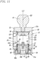
- the chuck piston 57 can be reciprocated in the direction of the third axis L3 by compressed air provided to and discharged from the first and second pressure chambers 52b, 52c of the cylinder hole 52a, and the permanent magnet 60 can be moved in the direction of the third axis L3 between an attracting position P1 (see Fig. 11 ) that is located adjacent to the distal end of the casing 51 to which the permanent magnet 60 is moved to attract a workpiece with the workpiece attracting surface 48a and a non-attracting position P2 (see Fig. 12 ) that is located adjacent to the proximal end of the casing 51 to which the permanent magnet 60 is moved to end the attraction of the workpiece 110.
- an attracting position P1 see Fig. 11
- P2 see Fig. 12
- the top cover 53 is fixed to the proximal end 51b of the casing 51 by bolts or other fasteners, and a distal end portion of the second ball member 41 is screwed to the middle of the top cover 53.
- the casing 51 of the chuck unit 50 has the cylinder hole 52a extending in the direction of the third axis L3 in which the permanent magnet 60 is moved between the attracting position P1 and the non-attracting position P2.
- the second ball member 41 protrudes from the proximal end of the casing 51.
- the chuck unit 50 has a vertically long cuboidal shape extending in the direction of the third axis L3.
- the support 70 includes the arm support member 71 having through holes 71a in which the support rods 6 of the magnetic chucks 5 are individually inserted in a reciprocable manner, a plurality of connectors 75 attached to the arm support member 71 and having communication holes 77 in which the support rods 6 of the magnetic chucks 5 are individually inserted, stoppers 3 attached to the corresponding support rods 6 and each configured to be brought into contact with the proximal end of the connector 75 when the support rod 6 is moved to prevent the support rod 6 from being detached from the through holes 71a, and compression coil springs 108 (spring members, compression springs) each located between the connector 75 and the support rod 6 of the respective magnet chucks 5 and configured to urge the magnetic chucks 5 toward the distal end in the direction of the first axis L1 relative to the arm support member 71.
- compression coil springs 108 spring members, compression springs
- the arm support member 71 has a plate-like shape, which extends in a direction perpendicular to the first axis L1 (horizontal direction) and has distal and proximal end surfaces at ends in the direction of the first axis L1, and multiple through holes 71a are provided in the arm support member 71 at equal intervals in the horizontal direction.
- a connecting support 71b protruding in the direction of the first axis L1 toward the proximal end is attached to the middle in the horizontal direction of the arm support member 71.
- a distal arm of a robot or a lift, for example, is connected to this connecting support 71b.
- the support rod 6 is inserted into each of the through holes 71a in the direction of the first axis L1.
- the connector 75 has a connecting body 76 extending in the direction of the first axis L1 and having a proximal end 76b (first end) and a distal end 76c (second end) at the ends.
- the connecting body 76 has the communication hole 77 extending therethrough in the direction of the first axis L1.
- a second locking mechanism 80 that can lock and unlock the support rod 6 against and from the arm support member 71 is provided in the communication hole 77 of the connecting body 76.
- the second locking mechanism 80 includes a proximal second locking mechanism 81 at the proximal end side of the communication hole 77 and a distal second locking mechanism 82 at the distal end side of the communication hole 77.
- the proximal second locking mechanism 81 includes a third cylinder hole 78 located at the proximal end side of the communication hole 77 in the connecting body 76 and extending in the direction of the first axis L1, a brake pad 83 having a pressing surface 83d facing the side surface of the support rod 6 in the third cylinder hole 78, a third piston 84 movable in the third cylinder hole 78 in the direction of the first axis L1 and having a sloping surface 84a located radially outward from the brake pad 83 relative to the first axis L1 in the third cylinder hole 78, and a pressing member 85 located between the brake pad 83 and the sloping surface 84a to receive a pressing force applied by the sloping surface 84a in a radially inward direction when the third piston 84 is moved, and a third pressure chamber 86 that is a portion of the third cylinder hole 78 defined by the third piston 84.
- the third cylinder hole 78 has a hollow cylindrical shape open at the proximal end of the connecting body 76, and the inner diameter of the third cylinder hole 78 is larger than that of the communication hole 77.
- the third cylinder hole 78 has an annular step 78a extending in a direction perpendicular to the direction of the first axis L1 at the distal end.
- the brake pad 83 having a hollow cylindrical shape is formed of an elastic member such as synthetic resin.
- the brake pad 83 includes separated multiple brake pieces 83a arranged at equal intervals in the circumferential direction.
- the brake pieces 83a each have a fan-like shape that extends radially outward from the first axis L1, and the brake piece 83a has an arc-shaped pressing surface 83d, which is a radially inner surface against which the side surface of the support rod 6 slides.
- the pressing surfaces 83d of the multiple brake pieces 83a that are arranged continuously in a circumferential direction form a portion of the through hole 83b that surrounds the outer peripheral surface of the support rod 6 and through which the support rod 6 is inserted.
- the pressing surface 83d has multiple annular grooves 83e, which open in the radially inward direction and surrounds the support rod 6, at intervals in the direction of the first axis L1.
- the brake piece 83a has a groove 83c that accommodates a portion of the pressing member 85 and extends in the direction of the first axis L1 in the outer surface.
- the third piston 84 has a cylindrical shape and has a through hole 84b extending therethrough in the direction of the first axis L1 in the middle.
- the support rod 6 is inserted in this through hole 84b in a movable manner in the direction of the first axis L1.
- the third piston 84 has a third hole 84c at the proximal end, and the third hole 84c is recessed to the middle of the third piston in the direction of the first axis L 1.
- the inner surface of the third hole 84c has a sloping surface 84a that extends annularly around the pressing member 85 and has an inner diameter gradually increasing toward the proximal end.
- the third piston 84 has an annular groove 84d extending in the circumferential direction in a distal end portion of the outer peripheral surface, and a sealing member 87 sealing between the outer peripheral surface of the third piston 84 and the inner peripheral surface of the third cylinder hole 78 is in the groove 84d. Furthermore, a sealing member 88 that seals between the inner surface of the through hole 84b and the side surface of the support rod 6 is in an annular groove extending in the circumferential direction in the inner surface of the through hole 84b of the third piston 84.
- the sealing members 87, 88 are lip seals, and lips 87a, 88a are tilted such that the outer diameter gradually increases toward the distal end in the direction of the first axis L1.
- the lips 87a, 88a prevent the compressed air from flowing from the distal end side to the proximal end side between the outer peripheral surface of the third piston 84 and the inner peripheral surface of the third cylinder hole 78 and between the inner surface of the through hole 84b and the side surface of the support rod 6.
- the pressing member 85 includes multiple metal balls 85a, and the balls 85a are in the corresponding grooves 83b of the brake pieces 83a.
- the balls 85a are supported by a ball support member 89.
- the ball support member 89 has a hollow cylindrical shape having a hole 89a open at the proximal end and has an annular flange 89b protruding radially outward from the proximal end of the ball support member 89.
- the flange 89b disposed on the proximal end of the connecting body 76 is fixed to the connecting body 76 by bolts 89c or other fasteners.
- the hole 89a is a hollow cylindrical hole extending in the direction of the first axis L1 toward the distal end, and the bottom surface of the hole 89a extends in a direction perpendicular to the direction of the first axis L1.
- the hole 89a has a through hole 89d, in which the support rod 6 is inserted, in the middle of the bottom surface.
- the hole 89a accommodates the brake pad 83 mounted on the support rod 6.
- the distal end of the brake pad 83 is in contact with the bottom surface of the hole 89a. This prevents the brake pad 83 from moving toward the distal end.
- the outer surface of the side wall 90 of the ball support member 89 has a sloping surface 90a having an outer diameter gradually increasing toward the proximal end.
- the sloping surface 90a extends substantially parallel to the sloping surface 84a of the third piston 84.
- the side wall 90 of the ball support member 89 has multiple apertures 90b for accommodating the balls 85a at equal intervals in the circumferential direction.
- the apertures 90b face the corresponding grooves 83c of the brake pieces 83a and extend radially through the side wall 90.
- the inner diameter of the apertures 90b is slightly larger than the diameter of the ball 85a, and the thickness of the side wall 90 (length of the aperture 90b) is smaller than the diameter of the ball 85a.
- the ball 85a can move radially in the aperture 90b, and ends of the ball 85a protrude from the ends of the aperture 90b.
- the radially inner end of the ball 85a is in contact with the inner surface of the groove 83c of the brake pad 83, and the radially outer end of the ball 85a is in contact with the sloping surface 84a of the third piston 84.
- the third pressure chamber 86 is a distal end portion of the third cylinder hole 78 and defined by the third piston 84.
- the third pressure chamber 86 is located between a top 84e at the distal end of the third piston 84 and the bottom surface of the third cylinder hole 78 and is in communication with the communication hole 77.
- the connecting body 76 has a supply and discharge port 92 in the middle in the direction of the first axis L1 through which compressed air is introduced from the outside into the communication hole 77.
- the distal second locking mechanism 82 has substantially the same configuration as the above-described proximal second locking mechanism 81. Thus, components different from those of the proximal second locking mechanism 81 are explained, and components having the same configurations as those of the proximal second locking mechanism 81 will not be described.
- the distal second locking mechanism 82 includes a fourth cylinder hole 79 located at the distal end side of the communication hole 77 in the connector 75, a brake pad 83 having a pressing surface 83d facing the side surface of the support rod 6 in the fourth cylinder hole 79, a fourth piston 94 movable in the fourth cylinder hole 79 and having a sloping surface 94a located radially outward from the brake pad 83 in the fourth cylinder hole 79, and a pressing member 85 located between the brake pad 83 and the sloping surface 94a to receive a pressing force applied by the sloping surface 94a in a radially inward direction when the fourth piston 94 is moved, and a fourth pressure chamber 95 that is a portion of the fourth cylinder hole 79 defined by the fourth piston 94.
- the fourth cylinder hole 79 has a hollow cylindrical shape open at the distal end of the connecting body 76, and the inner diameter of the fourth cylinder hole 79 is larger than that of the communication hole 77.
- the fourth cylinder hole 79 has an annular step 79a extending in a direction perpendicular to the direction of the first axis L 1 at the distal end.
- the brake pad 83 which is identical to the brake pad 83 of the proximal second locking mechanism 81, will not be explained.
- the fourth piston 94 has a through hole 94b extending therethrough in the middle and in which the support rod 6 is movable in the direction of the first axis L1.
- the fourth piston 94 has a fourth hole 94c at the distal end.
- the inner surface of the fourth hole 94c is a sloping surface 94a having an inner diameter gradually increasing toward the distal end.
- the fourth piston 94 has an annular groove 94d in a proximal end portion of the outer peripheral surface, and a sealing member 96 sealing between the outer peripheral surface of the fourth piston 94 and the inner peripheral surface of the fourth cylinder hole 79 is in the groove 94d. Furthermore, a sealing member 97 that seals between the inner surface of the through hole 94b and the side surface of the support rod 6 is in an annular groove in the inner surface of the through hole 94b of the fourth piston 94.
- the sealing members 96, 97 are lip seals, and lips 96a, 97a of the sealing members 96, 97 are tilted such that the outer diameter gradually increases from the distal end side toward the proximal end side.
- the lips 96a, 97a prevent the compressed air from flowing from the proximal end side to the distal end side between the outer peripheral surface of the fourth piston 94 and the inner peripheral surface of the fourth cylinder hole 79 and between the inner surface of the through hole 94b and the side surface of the support rod 6.
- the pressing member 85 includes multiple metal balls 85a, which are supported by the ball support member 89.
- the ball support member 89 has a cylindrical shape having the hole 89a open at the distal end.
- the flange 89b located at the distal end of the ball support member 89 is fixed to the distal end of the connecting body 76 by the bolts 89c or other fasteners.
- the support rod 6 is in the through hole 89d in the bottom surface of the hole 89a, and the hole 89a accommodates the brake pad 83 attached to the support rod 6.
- the proximal end of the brake pad 83 is in contact with the bottom surface of the hole 89a. This prevents the brake pad 83 from moving toward the distal end.
- the outer surface of the side wall 90 of the ball support member 89 has a sloping surface 90a that has an outer diameter gradually increasing toward the distal end.
- the sloping surface 90a extends parallel to the sloping surface 94a of the fourth piston.
- the side wall 90 of the ball support member 89 has multiple apertures 90b that accommodate the corresponding balls 85a.
- the radially inner end of the ball 85a in the aperture 90b is in contact with the inner surface of the groove 83c of the brake pad 83, and the radially outer end of the ball 85a is in contact with the sloping surface 94a of the fourth piston 94.
- the fourth pressure chamber 95 is a proximal end portion of the fourth cylinder hole 79 defined by the fourth piston 94.
- the fourth pressure chamber 95 is located between a top 94e at the proximal end of the fourth piston 94 and the bottom surface of the fourth cylinder hole 79 and is in communication with the communication hole 77.
- compressed air is supplied to or discharged from the third and fourth pressure chambers 86, 95 through the supply and exhaust port 92 and the communication hole 77 to start or end pushing of the third and fourth pistons 84, 94 against the pressing member 85.
- the balls 85a receive a pressing force in the radially inward direction from the sloping faces 84a, 94a. This pushes the brake pads 83, 83 in the radially inward direction, and the pressing surfaces 83d, 83d push the side surface of the support rod 6. This locks the support rod 6 against the arm support member 71 (the connecting body 76).
- a fixing member 100 which has an insertion hole 100a extending therethrough in the direction of the first axis L1 and is inserted in the through hole 71a of the arm support member 71, is attached to the proximal end of the connecting body 76.
- the fixing member 100 has a fixing body 101 that has a tubular shape extending in the direction of the first axis L1 and having a proximal end 101d and a distal end 101e, an annular flange 101a that protrudes radially outward from the distal end of the fixing body 101, and a tubular locking protrusion 101b protruding from the distal end of the fixing body 101.
- the flange 101a on the proximal end of the ball support member 89 is fixed to the ball support member 89 by screws 102 or other fasteners.
- the fixing member 100 is fixed to the connecting body 76 with the ball support member 89 therebetween.
- the locking protrusion 101b of the fixing member 100 is fitted in the hole 89a of the ball support member 89.
- the tip of the locking protrusion 101b is in contact with the proximal end of the brake pad 83.
- the brake pad 83 is sandwiched between the locking protrusion 101b and the bottom surface of the hole 89a of the ball support member 89 and thus cannot move toward ends in the direction of the first axis L1.
- the outer diameter of the fixing body 101 is smaller than the inner diameter of the through hole 71a of the arm support member 71, and the fixing body 101 has a male thread 101c on a proximal end portion of the side surface.
- the fixing body 101 When the fixing body 101 is in the through hole 71a of the arm support member 71 with the proximal end surface of the flange 101a being in contact with the distal end surface of the arm support member 71, the proximal end portion of the fixing body 101 protrudes from the through hole 71a.
- a mounting nut 103 is screwed to the male thread 101c of the protruding fixing body 101 to fix the fixing member 100 to the arm support member 71.
- the connecting body 76 is detachably fixed to the arm support member 71 with the fixing member 100 therebetween.
- a cover member 104 having an insertion hole 104a that extends therethrough in the direction of the first axis L1 is attached to the distal end 76c of the connecting body 76.
- the cover member 104 includes a tubular cover body 105 extending in the direction of the first axis L1 and an annular flange 105a protruding radially outward from the middle in the direction of the first axis L1 of the cover body 105.
- the flange 105a on the distal end of the ball support member 89 is fixed to the ball support member 89 by screws 102 or other fasteners.
- the cover member 104 is fixed to the connecting body 76 with the ball support member 89 therebetween.
- the proximal end of the cover body 105 is in contact with the distal end of the brake pad 83.
- the brake pad 83 is sandwiched between the cover body 105 and the bottom surface of the hole 89a of the ball support member 89 and thus cannot move toward ends in the direction of the first axis L 1.
- the support rod 6 has the stopper 3 attached to the proximal end 6b of the support rod 6 with its proximal end portion protruding from the proximal end of the insertion hole 100a of the fixing member 100.
- the stopper 3 has a cylindrical shape, and the diameter of the stopper 3 is larger than the inner diameter of the insertion hole 100a of the fixing member 100 and smaller than the inner diameter of the through hole 71a of the arm support member 71.
- the stopper 3 allows the stopper 3 to pass through the through hole 71a of the arm support member 71, and thus the stopper 3 can be inserted into and removed from the through hole 71a of the arm support member 71 with the stopper 3 attached to the support rod 6. Furthermore, the stopper 3 is larger than the inner diameter of the insertion hole 100a of the fixing member 100. When the support rod 6 is moved toward the distal end of the connector 75, the support rod 6 comes in contact with the proximal end 101d of the fixing body 101 of the fixing member 100, and thus the support rod 6 cannot detach from the connector 75.
- the connecting nut 2 screwed to the distal end of the support rod 6 has a larger diameter than the outer diameter of the support rod 6.
- the proximal end of the connecting nut 2 forms a spring seat 2b (stepped portion) that protrudes radially outward from the support rod 6.
- a compression coil spring (compression spring, spring member) 108 is located between the spring seat 2b and the cover member 104.
- the compression coil spring 108 has one end in contact with the distal end of the cover member 104 and the other end in contact with the spring seat 2b of the connecting nut 2 while having the support rod 6 in it.
- the compression coil spring 108 always urges the support rod 6 toward the distal end.
- the workpiece clamping device 1 includes the magnetic chucks 5 mounted on the arm support member 71.
- the magnetic chucks 5 are mounted on the arm support member 71 so that the support rods 6 are parallel to each other.
- the workpiece clamping device 1 attracts a workpiece 110 that has a surface (hereinafter, referred to as "upper surface”) at the proximal end in the direction of the first axis L1 (hereinafter, referred to as "vertical direction”) including a non-sloping surface, which extends in a direction perpendicular to the vertical direction (hereinafter, referred to as "left-right direction”), and sloping surfaces, which are tilted in different horizontal directions.
- upper surface a surface at the proximal end in the direction of the first axis L1
- vertical direction including a non-sloping surface, which extends in a direction perpendicular to the vertical direction (hereinafter, referred to as "left-right direction”), and sloping surfaces, which are tilted in different horizontal directions.
- the non-sloping surface and the sloping surfaces of the workpiece 110 are partly located at different high positions in the vertical direction.
- the workpiece 110 is a metal plate bent at multiple positions and has a first sloping surface 110a, a second sloping surface 110b, a non-sloping surface 110c, and a third sloping surface 110d, in this order from left to right.
- the first sloping surface 110a is an upward sloping surface that slopes upward from the left side to the right side.
- the second sloping surface 110b is a downward sloping surface that is located at the same height position as the first sloping surface 110a and slopes downward from the left side to the right side.
- the non-sloping surface 110c is located below the first and second sloping surfaces 110a, 110b and extends in the left-right direction.
- the third sloping surface 110d is a downward sloping surface that has a middle section in the left-right direction at the same height position as the non-sloping surface 110c and slopes downward at a smaller angle than the second sloping surface 110b.
- the workpiece clamping device 1 When the workpiece clamping device 1 is used to attract the workpiece 110 having such a configuration, the workpiece 110 is first placed under the workpiece clamping device 1. Then, as illustrated in Fig. 5 , the pivot arm 20 locked against the support rod 6 and the chuck unit 50 by the first locking mechanism 37 is unlocked, and the support rod 6 locked against the connecting body 76 by the second locking mechanism 80 is unlocked. Furthermore, the permanent magnet 60 of the chuck unit 50 is moved to the attracting position P1. This makes the support rod 6 movable in the vertical direction relative to the connecting body 76, and, when the entire magnetic chuck 5 is moved downward, the stopper 3 comes into contact with the proximal end 101d of the fixing member 100. This stops the magnetic chuck 5 from moving downward, and the entire magnetic chuck 5 is in a straight posture in the direction of the first axis L1.
- the combination of the downward movement of the magnetic chuck 5 and the pressing force of the compression coil spring 108 allows the pivot arm 20 to pivot in the left-right direction about the first central point S1 of the first j oint 10 and also allows the chuck unit 50 to pivot in the left-right direction about the second central point S2 of the second joint 40.
- the respective workpiece attracting surfaces 48a positioned along the first and second sloping surfaces 110a, 110b can come in contact with and attract the first and second sloping surfaces 110a, 110b without shifting from a predetermined position.
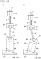
- the combination of the downward movement of the magnetic chuck 5 and the pressing force of the compression coil spring 108 allows the pivot arm 20 to pivot in the right direction about the first central point S1 of the first joint 10 and also allows the chuck unit 50 to pivot to the left side about the second central point S2 of the second joint 40.
- the workpiece attracting surface 48a positioned along the third sloping surface 110d can come in contact with and attract a workpiece without shifting from a predetermined position.
- the pivot arm 20 does not pivot about the first central point S1 of the first joint 10 and the second central point S2 of the second joint 40, and thus the magnetic chuck 5 is kept in a straight posture.
- the workpiece attracting surface 48a positioned along the non-sloping surface 110c can come in contact with and attract a workpiece without shifting from a predetermined position.
- the proximal end of the pivot arm 20 is pivotably connected to the distal end of the support rod 6 through the first joint 10, and the distal end of the pivot arm 20 is pivotably connected to the proximal end of the chuck unit 50 through the second joint 40.
- the chuck unit 50 is vertically long but may be horizontally long, i,e., may have a width larger than the length in the direction of the third axis L3.
Landscapes
- Engineering & Computer Science (AREA)
- Mechanical Engineering (AREA)
- Robotics (AREA)
- Manipulator (AREA)
- Jigs For Machine Tools (AREA)
Abstract
Description
- The present invention relates to a workpiece clamping device including a magnetic chuck that attracts a workpiece with a magnetic force.
- A magnetic chuck that includes an electromagnet in a casing and a magnetic chuck that includes a permanent magnet attached to a piston movable in a cylinder hole of a casing and moved together with the piston are conventionally known, for example, as described in
Patent Literatures - The magnetic chuck described in
Patent Literature 1 includes an electromagnet in a casing and has a workpiece attracting surface extending in a horizontal direction perpendicular to the vertical direction on a lower surface of the casing. When the electromagnet is activated, a magnetic force is generated on the workpiece attracting surface, and thus the magnetic chuck can attract a workpiece with the workpiece attracting surface. The magnetic chuck can be moved vertically by a lift connected to the upper surface of the casing. - The magnetic chuck described in
Patent Literature 2 has a cylinder hole in the casing and includes a piston that can move vertically in the cylinder hole. A permanent magnet is attached to the lower portion of the piston, and the permanent magnet can move vertically in the cylinder hole together with the piston. The magnetic chuck has a workpiece attracting surface that extends in a horizontal direction perpendicular to the vertical direction at the lower end, and a robot arm that moves the magnetic chuck in the vertical direction is connected to the upper end. - When these magnetic chucks attract a workpiece, an upper surface of the workpiece may be tilted with respect to the workpiece attracting surface. In such a case, a portion of the workpiece attracting surface touches the upper surface of the workpiece when the magnetic chuck moves down, and the workpiece attracting surface cannot be positioned along the upper surface of the workpiece. Thus, the magnetic chuck is unable to attract the workpiece with the workpiece attracting surface.
- To solve this problem, a joint described in
Patent Literature 3, i.e., a joint that enables the magnetic chuck to pivot about an axis perpendicular to the vertical direction, may be provided at an upper portion of each of the magnetic chucks described inPatent Literatures - However, when the magnetic chuck moves downward while pivoting about the axis of the j oint, the workpiece attracting surface attracts the upper surface of the workpiece at a position shifted from a predetermined position. The shifting amount of the magnetic chuck having a permanent magnet movable within a frame is large, because the dimension in the vertical dimension is larger than the dimension in the horizontal direction.
-
- PTL 1:
Japanese Unexamined Patent Application Publication No. 7-171784 - PTL 2:
Japanese Unexamined Patent Application Publication No. 2019-186324 - PTL 3:
Japanese Registered Utility Model No. 3087910 - In view of the above, the technical object of the present invention is to provide a workpiece clamping device that can attract a workpiece, even when an upper surface of the workpiece is tilted with respect to the workpiece attracting surface, with the workpiece attracting surface positioned along a predetermined portion of the upper surface of the workpiece.
- To solve the problem, a workpiece clamping device according to the present invention comprises a magnetic chuck including: a support rod that is reciprocable in a direction of a first axis and has a distal end and a proximal end at ends in a movement direction thereof, a pivot arm that has a first end and a second end at ends in a direction of a second axis and is pivotably connected to the distal end of the support rod at the first end through a first j oint, a chuck unit that includes a casing having a distal end and a proximal end at ends in a direction of a third axis and pivotably connected to the second end of the pivot arm at the proximal end of the casing through a second joint and that is configured to attract a workpiece with a magnetic force, wherein, in the chuck unit, the magnetic chuck has a workpiece attracting surface extending in a direction perpendicular to the third axis at the distal end of the casing, the first joint has a first central point, the support rod and the pivot arm are pivotable relative to each other about the first central point, the second joint has a second central point, and the pivot arm and the chuck unit are pivotable relative to each other about the second central point.
- In this case, preferably, the chuck unit has a cylinder hole extending in the direction of the third axis in the casing, a chuck piston movable in the cylinder hole, and a permanent magnet attached to the chuck piston to move with the chuck piston, and the permanent magnet is reciprocable in the direction of the third axis between an attracting position that is located adjacent to the distal end of the casing to which the permanent magnet is moved to attract a workpiece with the workpiece attracting surface and a non-attracting position that is located adj acent to the proximal end of the casing to which the permanent magnet is moved to end the attraction of the workpiece.
- Furthermore, preferably, the first joint includes a first ball member having the first central point and a first recess accommodating the first ball member in a slidable manner, and the second joint includes a second ball member having the second central point and a second recess accommodating the second ball member in a slidable manner. Furthermore, preferably, in the first j oint, the first ball member is attached to the support rod and the first recess is open at the first end of the pivot arm, and, in the second joint, the second ball member is attached to the proximal end of the chuck unit and the second recess is open at the second end of the pivot arm.
- Furthermore, preferably, the pivot arm has a first locking mechanism that enables and disables relative pivoting between the first ball member in the first recess and the first recess of the first joint and relative pivoting between the second ball member in the second recess and the second recess of the second joint.
- In this case, preferably, the pivot arm has a first cover member attached to the first end of the pivot arm and having a first through hole extending therethrough in the direction of the second axis and a second cover member attached to the second end of the pivot arm and having a second through hole extending therethrough in the direction of the second direction, the first locking mechanism includes: the first and second through holes in the first and second cover members; first and second cylinder holes in first and second end portions of the pivot arm; a first piston movable in the first cylinder hole and having a first hole open at the first end; a second piston movable in the second cylinder hole and having a second hole open at a second end; a first pressure chamber located in a second end portion of the first cylinder hole in the direction of the second axis and defined by the first piston; and a second pressure chamber located in a first end portion of the second cylinder hole in the direction of the second axis and defined by the second piston, the first through hole and the first hole are in communication with each other in the direction of the second axis, and an inner space defined by the first through hole and the first hole is the first recess accommodating the first ball member, an inner surface of the first through hole has a first outer sliding-contact surface that is in sliding contact with a portion of the outer surface of the first ball member that is adjacent to the first end in the direction of the second axis, an inner surface of the first hole has a first inner sliding-contact surface that is in sliding contact with a portion of the outer surface of the first ball member that is adjacent to the second end in the direction of the second axis, the second through hole and the second hole are in communication with each other in the direction of the second axis, and an inner space defined by the second through hole and the second hole is the second recess accommodating the second ball member, an inner surface of the second through hole has a second outer sliding-contact surface that is in sliding contact with a portion of the outer surface of the second ball member that is adjacent to the second end in the direction of the second axis, an inner surface of the second hole has a second inner sliding-contact surface that is in sliding contact with a portion of the outer surface of the second ball member that is adjacent to the second end in the direction of the second axis, the first and second pistons are reciprocated in the direction of the second axis by compressed air provided to and discharged from the first and second pressure chambers of the first and second cylinder holes, and when the first piston is moved toward the first end in the direction of the second axis and the second piston is moved toward the second end in the direction of the second axis by the compressed air provided to the first and second pressure chambers, the first ball member is held on the first outer sliding-contact surface and the first inner sliding-contact surface and the second ball member is held on the second outer sliding-contact surface and the second inner sliding-contact surface, allowing the pivot arm to be locked against the support rod and the chuck unit.
- Furthermore, preferably, the first outer sliding-contact surface of the first through hole is in contact with a portion of the outer surface of the first ball member that is away from the first central point toward the first end in the direction of the second axis, the first inner sliding-contact surface of the first hole is in contact with a portion of the outer surface of the first ball member that is away from the first central point toward the second end in the direction of the second axis, the second outer sliding-contact surface of the second through hole is in contact with a portion of the outer surface of the second ball member that is away from the second central point toward the second end in the direction of the second axis, and the second inner sliding-contact surface of the second hole is in contact with a portion of the outer surface of the second ball member that is away from the second central point toward the first end in the direction of the second axis. Furthermore, preferably, the first inner sliding-contact surface of the first piston is a conical surface having an inner diameter gradually increasing toward the first end in the direction of the second axis, and the second inner sliding-contact surface of the second piston is a conical surface having an inner diameter gradually increasing toward the second end in the direction of the second axis.
- The workpiece clamping device according to the present invention comprises the magnetic chucks according to any one of
claims 5 to 8 including a plurality of magnetic chucks, and a support supporting the support rods of the magnetic chucks in a reciprocable manner, wherein the support includes: an arm support member extending in a direction perpendicular to the first axis and having through holes in which the support rods of the magnetic chucks are individually inserted in a reciprocable manner; a plurality of connectors attached to the arm support member and having communication holes in which the support rods of the magnetic chucks are individually inserted; the plurality of connectors having a second locking mechanism configured to lock and unlock the support rod against and from the arm support member; stoppers attached to the corresponding support rods and, when the support rods are moved, the stoppers each come in contact with the first end of the connector to prevent the support rod from being detached from the through holes; and spring members each located between the connector and the support rod of the corresponding magnetic chucks and configured to urge the magnetic chucks toward the first end in the direction of the first axis against the arm support member, and the support rods of the magnetic chucks are positioned at intervals with the first axes being parallel to each other on the arm support member. - In this case, preferably, the second locking mechanism of the connector includes: a third cylinder hole extending in the direction of the first axis in the communication hole of the connector; a brake pad having a pressing surface facing a side surface of the support rod in the third cylinder hole; a third piston movable in the third cylinder hole in the direction of the first axis and having a sloping surface located radially outward from the brake pad relative to the first axis in the third cylinder hole; a pressing member located between the brake pad and the sloping surface and configured to receive a pressing force applied in a radially inward direction by the sloping surface when the third piston moves; and a third pressure chamber that is a portion of the third cylinder hole defined by the third piston, wherein compressed air provided to the third pressure chamber of the third cylinder hole allows the third piston to reciprocate in the direction of the first axis, and when the compressed air provided to the third pressure chamber moves the third piston, the pressing member pushes the brake pad in the radially inward direction upon reception of a pressing force applied in the radially inward direction by the sloping surface, and the pressing surface pushes a side surface of the support rod, locking the support rod against the arm support member.
- Furthermore, preferably, the connector includes a connecting body having first and second ends at ends in the direction of the first axis, connected to the arm support member at the first end, and having the communication hole in it, the connecting body has a fixing member attached to the first end, the fixing member has an insertion hole extending therethrough in the direction of the first axis and is located in the through hole of the arm support member, the insertion hole is in communication with the communication hole of the connecting body, and the support rod is located in the insertion hole and the communication hole, and the fixing member in the through hole of the arm support member is detachably attached to the arm support member, allowing the connecting body to be detachably attached to the arm support member.
- Furthermore, preferably, the fixing member attached to the arm support member protrudes from a surface at the first end in the direction of the first axis of the arm support member, the support rod has a proximal end portion protruding from an end in the direction of the first axis of the insertion hole, the stopper is attached to the end portion, and the stopper has a cylindrical shape having a diameter larger than an inner diameter of the insertion hole of the fixing member and smaller than an inner diameter of the through hole of the arm support.
- Furthermore, preferably, the spring member is a compression spring located between the second end of the connecting body and the first end of the support rod.
- As described above, the present invention can provide a workpiece clamping device that can attract a workpiece, even when an upper surface of the workpiece is tilted with respect to the workpiece attracting surface, with the workpiece attracting surface positioned along a predetermined portion of the upper surface of the workpiece.
-
- [
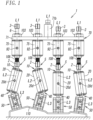
Fig. 1] Fig. 1 is a front view of a workpiece clamping device according to an embodiment of the present invention. - [
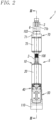
Fig. 2] Fig. 2 is a side view of the workpiece clamping device. - [
Fig. 3] Fig. 3 is a cross-sectional view of the workpiece clamping device viewed in a direction of III-III arrow inFig. 2 . - [
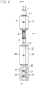
Fig. 4] Fig. 4 is a front view of a magnetic check in an extended state with a connector attached. - [
Fig. 5] Fig. 5 is a cross-sectional view of the magnetic check and the connector viewed in a direction of V-V arrow inFig. 4 . - [
Fig. 6] Fig. 6 is a front view of a pivot arm. - [
Fig. 7] Fig. 7 is a plan view of the pivot arm. - [
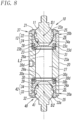
Fig. 8] Fig. 8 is a cross-sectional view of the pivot arm viewed in a direction of VIII-VIII arrow inFig. 6 . - [
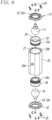
Fig. 9] Fig. 9 is an exploded perspective view of the pivot arm. - [
Fig. 10] Fig. 10 is a cross-sectional view of the pivot arm when first and second joints are in a pivotable state. - [
Fig. 11] Fig. 11 is a cross-sectional view of a chuck unit having a permanent magnet moved to an attracting position. - [
Fig. 12] Fig. 12 is a cross-sectional view of the chuck unit having the permanent magnet moved to a non-attracting position. - [
Fig. 13] Fig. 13 is a front view of the connector in which a support rod is inserted. - [
Fig. 14] Fig. 14 is a cross-sectional view of the support rod and the connector viewed in a direction of XIV-XIV inFig. 13 . - [
Fig. 15] Fig. 15 is a magnified cross-sectional view of the connector inFig. 14 . - [
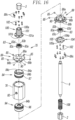
Fig. 16] Fig. 16 is an exploded perspective view of the support rod and the connector. - [
Fig. 17] Fig. 17 is a view illustrating how the chuck unit attracts a workpiece when an upper surface of the workpiece is tilted upward with respect to a workpiece attracting surface. - [
Fig. 18] Fig. 18 is a view illustrating how the chuck unit attracts a workpiece when an upper surface of the workpiece is tilted downward with respect to the workpiece attracting surface. - Hereinafter, a workpiece clamping device according to the present invention will be described. In this embodiment, a workpiece clamping device that includes multiple magnetic chucks and in which chuck units of the magnetic chucks each have a permanent magnet movable in the casing is used as an example. The workpiece clamping device may include one magnetic chuck. The magnetic chuck may have an electromagnet fixed in the casing.
-
Figs. 1 to 3 illustrate an embodiment of theworkpiece clamping device 1 according to the present invention. Theworkpiece clamping device 1 includes multiplemagnetic chucks 5 and asupport 70. Themagnetic chucks 5 are supported by thesupport 70 in a reciprocable manner. In this embodiment, fourmagnetic chucks 5 are provided for thesupport 70, and thesupport 70 is connected to, for example, a robot distal end arm or a lift, and the entireworkpiece clamping device 1 is movable in a direction perpendicular to anarm support member 71 of the support 70 (hereinafter, may be referred to as "a direction of thefirst axis L 1 "). - As illustrated in
Fig. 5 , themagnetic chuck 5 has asupport rod 6, which can reciprocate in the direction of the first axis L1 and has adistal end 6a and aproximal end 6b at ends in the movement direction, apivot arm 20, which has aproximal end 20b (first end) and adistal end 20a (second end) at ends in a direction of a second axis L2 and is pivotably connected to thedistal end 6a of thesupport rod 6 through a first joint 10 at theproximal end 20b, and achuck unit 50, which has acasing 51 having adistal end 51a and aproximal end 51b at ends in a direction of a third axis L3 and is pivotably connected to thedistal end 20a of thepivot arm 20 through a second joint 40 at theproximal end 51b of thecasing 51. Thechuck unit 50 attracts a workpiece with a magnetic force. In this embodiment, themagnetic chuck 5 includes thesupport rod 6, the first joint 10, thepivot arm 20, the second joint 40, and thechuck unit 50, in this order from the proximal end to the distal end in the direction of the first axis L1.Fig. 5 illustrates a state in which thesupport rod 6 is in aconnector 75, which will be described later. - In this embodiment, the
support rod 6 has an elongated cylindrical shape extending in the direction of the first axis L1. Astopper 3, which will be described later, is screwed to theproximal end 6b of thesupport rod 6, and a connectingnut 2 is screwed to thedistal end 6a of thesupport rod 6. - As illustrated in
Figs. 5 and8 to 10 , the first joint 10 includes afirst ball member 11 and afirst recess 12 that accommodates thefirst ball member 11 in a slidable manner. The first joint has a first central point S1 at the center, and thesupport rod 6 and thepivot arm 20 are connected to each other in a pivotable manner about the first central point S1. - In this embodiment, the
first ball member 11 is spherical, and thefirst ball member 11 is screwed to the connectingnut 2 at the proximal end in the direction of the first axis L1. The first central point S1 is on the first axis L1. - The
first recess 12 is open at theproximal end 6a in the direction of extension (in the direction of the second axis L2) of thepivot arm 20. In this embodiment, as illustrated inFigs. 8 and9 , thefirst recess 12 is composed of a first throughhole 22 of afirst cover member 21 attached to theproximal end 20b of thepivot arm 20 and afirst hole 24 of afirst piston 23 provided in a proximal end portion of thepivot arm 20 and open toward the proximal end (one end) in the direction of the second axis L2. The first throughhole 22 and thefirst hole 24 are in communication with each other in the direction of the second axis L2, and aninner space 26 defined by the first throughhole 22 and thefirst hole 24 is thefirst recess 12 that accommodates thefirst ball member 11. - The
first cover member 21 has a plate-like shape in this embodiment, and thefirst cover member 21 is fixed to theproximal end 20b of thepivot arm 20 bybolts 25 or other fastening members at the outer peripheral portion. Thefirst cover member 21 has the first throughhole 22, which extends therethrough in the direction of the second axis L2, in the middle. The first throughhole 22 has openings at ends in the direction of the second axis L2 of thefirst cover member 21, and its inner surface is a first outer sliding-contact surface 22a that extends annularly around the second axis L2 and is in sliding contact with a proximal end portion of the outer surface of thefirst ball member 11. The first outer sliding-contact surface 22a is in contact with a portion of the outer surface of thefirst ball member 11 that is away from the first central point S1 toward the proximal end in the direction of the second axis L2. - In this embodiment, the
first hole 24 of thefirst piston 23 has a hemispherical shape recessed from the proximal end toward the distal end in the direction of the second axis L2, and the inner surface of thefirst hole 24 is a first inner sliding-contact surface 24a that is in sliding contact with a distal end portion of the outer surface of thefirst ball member 11. The first inner sliding-contact surface 24a is a conical surface having an inner diameter gradually increasing toward the proximal end and is in contact with a portion of the outer surface of thefirst ball member 11 that is away from the first central point S1 toward the distal end in the direction of the second axis L2. - As described above, the
first ball member 11 is supported in thefirst recess 12 in a pivotable manner as illustrated inFigs. 5 and10 , and thus thesupport rod 6 and thepivot arm 20 are pivotable about the first central point S1 of thefirst ball member 11 with respect to each other. Thefirst piston 23 will be described in detail later. - In this embodiment, as illustrated in
Figs. 6 to 10 , thepivot arm 20 has a tubular shape extending in the direction of the second axis L2. Thepivot arm 20 has an arm throughhole 27 extending therethrough in the direction of the second axis L2 and has afirst cylinder hole 28 and asecond cylinder hole 29 in proximal and distal end portions of thepivot arm 20. The first and second cylinder holes 28, 29 have the same inner diameter and the same depth and have a diameter larger than the inner diameter of the arm throughhole 27. Thefirst piston 23 is movably located in thefirst cylinder hole 28, and thesecond piston 30 is movably located in thesecond cylinder hole 29. - The depth of the
first cylinder hole 28 is such that agap 31 is formed between a top 23a at the distal end of thefirst piston 23 and the bottom surface of thefirst cylinder hole 28 when the first inner sliding-contact surface 24a of thefirst piston 23 is in contact with the outer surface of thefirst ball member 11. When thefirst piston 23 is retracted in thisgap 31 toward the distal end, thefirst ball member 11 can pivot relative to thefirst recess 12. - In this embodiment, as illustrated in
Figs. 8 and10 , thefirst piston 23 has a cylindrical shape and has anannular groove 23b extending in the circumferential direction on a distal end portion of the outer peripheral surface of thefirst piston 23. A sealingmember 23c is in thisgroove 23b to seal between the outer peripheral surface of thefirst piston 23 and the inner peripheral surface of thefirst cylinder hole 28. The sealingmember 23c is a lip seal, and alip 23d of the sealingmember 23c is tilted such that the outer diameter gradually increases toward the distal end of thefirst piston 23. Thus, thelip 23d prevents the compressed air from flowing from the distal end side to the proximal end side between the outer peripheral surface of thefirst piston 23 and the inner peripheral surface of thefirst cylinder hole 28. - The
first cylinder hole 28 has afirst pressure chamber 28a, which is defined by thefirst piston 23, in a distal end portion. In this embodiment, thefirst pressure chamber 28a is located between the top 23a of thefirst piston 23 and the bottom surface of thefirst cylinder hole 28 and is in communication with the arm throughhole 27. Thepivot arm 20 has a supply andexhaust port 20d in the middle in the direction of the second axis L2 through which compressed air can enter the arm throughhole 27 from the outside. - As illustrated in
Figs. 5 , andFigs. 8 to 10 , in this embodiment, a second joint 40, which connects thedistal end 20a of thepivot arm 20 and theproximal end 51b of thecasing 51 of thechuck unit 50, has a configuration similar to that of the first joint 10 described above and includes asecond ball member 41 and asecond recess 42 that accommodates thesecond ball member 41 in a slidable manner. The second joint 40 has a second central point S2, and thepivot arm 20 and thechuck unit 50 are connected to each other in a pivotable manner about the second central point S2. - In this embodiment, the
second ball member 41 is spherical, and thesecond ball member 41 is screwed to thecasing 51 of thechuck unit 50 at the distal end in the direction of the third axis L3 (the direction of extension of the chuck unit 50). The second central point S2 is on the third axis L3. - The
second recess 42 has an opening at the distal end of thepivot arm 20. In this embodiment, thesecond recess 42 is composed of a second throughhole 33 of asecond cover member 32 attached to the distal end of thepivot arm 20 and asecond hole 34 provided in the distal end portion of thepivot arm 20 and open toward the distal end side in the direction of the second axis L2 of asecond piston 30. The second throughhole 33 and thesecond hole 34 are in communication with each other in the direction of the third axis L3, and aninner space 35 defined by the second throughhole 33 and thesecond hole 34 is thesecond recess 42 that accommodates thesecond ball member 41. - As illustrated in
Figs. 8 to 10 , thesecond cover member 32 has a plate-like shape in this embodiment, and thesecond cover member 32 is fixed to thedistal end 20a of thepivot arm 20 bybolts 25 or other fastening members at the outer peripheral portion. Thesecond cover member 32 has the second throughhole 33, which extends therethrough in the direction of the second axis L2, in the middle. The second throughhole 33 has openings at ends in the direction of the second axis L2, and the inner surface of the second throughhole 33 is a second outer sliding-contact surface 33a that extends annularly around the second axis L2 and is in sliding contact with a second end portion of the outer surface of thesecond ball member 41. The second outer sliding-contact surface 33a is in contact with a portion of the outer surface of thesecond ball member 41 that is away from the second central point S2 toward the distal end in the direction of the second axis L2. - The
second hole 34 of thesecond piston 30 has a hemispherical shape recessed from the distal end side to the proximal end side in this embodiment. The inner surface of thesecond hole 34 is a second inner sliding-contact surface 34a that is in sliding contact with a proximal end portion of the outer surface of thesecond ball member 41. The second inner sliding-contact surface 34a is a conical surface having an inner diameter gradually increasing toward the distal end and is in contact with a portion of the outer surface of thesecond ball member 41 that is away from the second central point S2 toward the proximal end in the direction of the second axis L2. - As described above, the
second ball member 41 is supported in thesecond recess 42 in a pivotable manner, and thus thepivot arm 20 and thechuck unit 50 illustrated inFig. 5 are pivotable about the second central point S2 of thesecond ball member 41 with respect to each other. - Furthermore, in this embodiment, the depth of the
second cylinder hole 29, which accommodates thesecond piston 30 in a movable manner, is such that agap 31 is formed between a top 30a at the proximal end of thesecond piston 30 and the bottom surface of thesecond cylinder hole 29 when the second inner sliding-contact surface 34a of thesecond piston 30 is in contact with the outer surface of thesecond ball member 41. When thesecond piston 30 is retracted in thisgap 31 toward the proximal end, thesecond ball member 41 can pivot relative to thesecond recess 42. - Furthermore, in this embodiment, the
second piston 30 has a cylindrical shape and has anannular groove 30b extending in the circumferential direction on the outer peripheral surface of thesecond piston 30. A sealingmember 30c is in thisgroove 30b to seal between the outer peripheral surface of thesecond piston 30 and the inner peripheral surface of thesecond cylinder hole 29. The sealingmember 30c is a lip seal, and alip 30d of the sealingmember 30c is tilted such that the outer diameter gradually increases from the distal end side toward the proximal end side. Thus, thelip 30d prevents the compressed air from flowing from the proximal end side to the distal end side between the outer peripheral surface of thesecond piston 30 and the inner peripheral surface of thesecond cylinder hole 29. - The
second cylinder hole 29 has asecond pressure chamber 29a, which is defined by thesecond piston 30, in a proximal end portion. In this embodiment, thesecond pressure chamber 29a is located between the top 30a at the proximal end side of thesecond piston 30 and the bottom surface of thesecond cylinder hole 29 and is in communication with the arm throughhole 27. - As illustrated in
Figs. 8 and10 , thepivot arm 20 has afirst locking mechanism 37 that enables and disables relative pivoting in the first joint 10 between thefirst ball member 11 in thefirst recess 12 and thefirst recess 12, and relative pivoting in the second joint 40 between thesecond ball member 41 in thesecond recess 42 and thesecond recess 42. - In this embodiment, the
first locking mechanism 37 includes the first and second throughholes second cover members pivot arm 20, thefirst piston 23 movably located in thefirst cylinder hole 28, thesecond piston 30 movably located in thesecond cylinder hole 29, thefirst pressure chamber 28a in thefirst cylinder hole 28, and thesecond pressure chamber 29a in thesecond cylinder hole 29. - In the
first locking mechanism 37, when compressed air is introduced into the arm throughhole 27 from the supply andexhaust port 20d, the compressed air is provided to the first andsecond pressure chambers second pistons first ball member 11 to be held on the first outer sliding-contact surface 22a and the first inner sliding-contact surface 24a and thesecond ball member 41 to be held on the second outer sliding-contact surface 33a and the second inner sliding-contact surface 34a, disabling pivoting of thepivot arm 20 relative to thesupport rod 6 and thechuck unit 50 illustratedFig. 5 . - When the compressed air in the
arm communication hole 27 is discharged through the supply andexhaust port 20d, the pressing force of the first andsecond pistons second ball members first ball member 11 is not held on the first outer sliding-contact surface 22a and the first inner sliding-contact surface 24a, and thesecond ball member 41 is not held on the second outer sliding-contact surface 33a and the second inner sliding-contact surface 34a, and thus thepivot arm 20 can pivot relative to thesupport rod 6 and thechuck unit 50 illustrated inFig. 5 , i.e., be in an unlocked state. - Next, the
chuck unit 50 is described. As illustrated inFigs. 5 ,11 , and12 , thechuck unit 50 includes acasing 51, acylinder hole 52a extending in the direction of the third axis L3 in thecasing 51, achuck piston 57 movable in thecylinder hole 52a, and apermanent magnet 60 attached to thechuck piston 57 to move together with thechuck piston 57. Thechuck unit 50 attracts theworkpiece 110 with a magnetic force. - In this embodiment, the
casing 51 has a cuboidal shape extending in the direction of the third axis L3 and includes acylinder tube 52 having thecylinder hole 52a in it, atop cover 53 attached to the proximal end of thecylinder tube 52, abottom cover 54 attached to the distal end of thecylinder tube 52. Thecylinder hole 52a is divided by thechuck piston 57 into afirst pressure chamber 52b located at the proximal end side in the direction of the third axis L3 and asecond pressure chamber 52c located at the distal end side in the direction of the third axis L3. - The
side wall 52e of thecylinder tube 52 has afirst port 52d through which air is supplied and exhausted at a distal end side, and thefirst port 52d is in communication with thesecond pressure chamber 52c. Theside wall 52e of thecylinder tube 52 has asecond port 52f through which air is supplied and exhausted at a proximal end side, and thesecond port 52f is in communication with thefirst pressure chamber 52b. Alatch yoke 56 is in a proximal end portion of thecylinder hole 52a and closes the opening of thecylinder hole 52a at the proximal end. - The
chuck piston 57 includes a disc-shapedseal holder 58 located at the proximal end, acore yoke 59 attached to the middle of the distal end face of theseal holder 58, apermanent magnet 60 located circumferentially outwardly from thecore yoke 59, acover yoke 61 located circumferentially outwardly from thepermanent magnet 60, and aring plate 62 attached to the distal end of thepermanent magnet 60. - The
seal holder 58 has an annular groove in the outer peripheral surface, and apiston seal 63 that is in sliding contact with the inner surface of thecylinder hole 52a is in the annular groove. Thecore yoke 59 has a cylindrical shape, and thecore yoke 59 has arecess 59b open at the distal end. - The
cover yoke 61 has a hollow cylindrical shape and is attached to the outer periphery of the distal end surface of theseal holder 58. Thecover yoke 61 has wear rings 65, 65 in two annular grooves located at the proximal end side. These wear rings 65, 65 guide and support thechuck piston 57 along thecylinder hole 52a. There is anannular space 66 between the inner peripheral surface of thecover yoke 61 and the outer peripheral surface of thecore yoke 59, and thepermanent magnet 60 is in thisspace 66. - The
bottom cover 54 has a disc-shape and closes the opening of thecylinder hole 52a at the distal end. Thebottom cover 54 has aworkpiece attracting surface 48a extending in a direction perpendicular to the third axis L3 at the distal end. - In the
chuck unit 50 having the above-describe configured, thechuck piston 57 can be reciprocated in the direction of the third axis L3 by compressed air provided to and discharged from the first andsecond pressure chambers cylinder hole 52a, and thepermanent magnet 60 can be moved in the direction of the third axis L3 between an attracting position P1 (seeFig. 11 ) that is located adjacent to the distal end of thecasing 51 to which thepermanent magnet 60 is moved to attract a workpiece with theworkpiece attracting surface 48a and a non-attracting position P2 (seeFig. 12 ) that is located adjacent to the proximal end of thecasing 51 to which thepermanent magnet 60 is moved to end the attraction of theworkpiece 110. - The
top cover 53 is fixed to theproximal end 51b of thecasing 51 by bolts or other fasteners, and a distal end portion of thesecond ball member 41 is screwed to the middle of thetop cover 53. - As above, the
casing 51 of thechuck unit 50 has thecylinder hole 52a extending in the direction of the third axis L3 in which thepermanent magnet 60 is moved between the attracting position P1 and the non-attracting position P2. Thesecond ball member 41 protrudes from the proximal end of thecasing 51. Thus, thechuck unit 50 has a vertically long cuboidal shape extending in the direction of the third axis L3. - Next, the
support 70 is described. As illustrated n inFigs. 1 and3 , thesupport 70 includes thearm support member 71 having throughholes 71a in which thesupport rods 6 of themagnetic chucks 5 are individually inserted in a reciprocable manner, a plurality ofconnectors 75 attached to thearm support member 71 and havingcommunication holes 77 in which thesupport rods 6 of themagnetic chucks 5 are individually inserted,stoppers 3 attached to thecorresponding support rods 6 and each configured to be brought into contact with the proximal end of theconnector 75 when thesupport rod 6 is moved to prevent thesupport rod 6 from being detached from the throughholes 71a, and compression coil springs 108 (spring members, compression springs) each located between theconnector 75 and thesupport rod 6 of the respective magnet chucks 5 and configured to urge themagnetic chucks 5 toward the distal end in the direction of the first axis L1 relative to thearm support member 71. - In this embodiment, the
arm support member 71 has a plate-like shape, which extends in a direction perpendicular to the first axis L1 (horizontal direction) and has distal and proximal end surfaces at ends in the direction of the first axis L1, and multiple throughholes 71a are provided in thearm support member 71 at equal intervals in the horizontal direction. A connectingsupport 71b protruding in the direction of the first axis L1 toward the proximal end is attached to the middle in the horizontal direction of thearm support member 71. A distal arm of a robot or a lift, for example, is connected to this connectingsupport 71b. Thesupport rod 6 is inserted into each of the throughholes 71a in the direction of the first axis L1. - As illustrated in
Figs. 3 and13 to 16 , theconnector 75 has a connectingbody 76 extending in the direction of the first axis L1 and having aproximal end 76b (first end) and adistal end 76c (second end) at the ends. The connectingbody 76 has thecommunication hole 77 extending therethrough in the direction of the first axis L1. - A
second locking mechanism 80 that can lock and unlock thesupport rod 6 against and from thearm support member 71 is provided in thecommunication hole 77 of the connectingbody 76. In this embodiment, thesecond locking mechanism 80 includes a proximalsecond locking mechanism 81 at the proximal end side of thecommunication hole 77 and a distalsecond locking mechanism 82 at the distal end side of thecommunication hole 77. - As illustrated in
Figs. 14 to 16 , the proximalsecond locking mechanism 81 includes athird cylinder hole 78 located at the proximal end side of thecommunication hole 77 in the connectingbody 76 and extending in the direction of the first axis L1, abrake pad 83 having apressing surface 83d facing the side surface of thesupport rod 6 in thethird cylinder hole 78, athird piston 84 movable in thethird cylinder hole 78 in the direction of the first axis L1 and having asloping surface 84a located radially outward from thebrake pad 83 relative to the first axis L1 in thethird cylinder hole 78, and a pressingmember 85 located between thebrake pad 83 and thesloping surface 84a to receive a pressing force applied by thesloping surface 84a in a radially inward direction when thethird piston 84 is moved, and athird pressure chamber 86 that is a portion of thethird cylinder hole 78 defined by thethird piston 84. - In this embodiment, the
third cylinder hole 78 has a hollow cylindrical shape open at the proximal end of the connectingbody 76, and the inner diameter of thethird cylinder hole 78 is larger than that of thecommunication hole 77. Thethird cylinder hole 78 has anannular step 78a extending in a direction perpendicular to the direction of the first axis L1 at the distal end. - Furthermore, in this embodiment, the
brake pad 83 having a hollow cylindrical shape is formed of an elastic member such as synthetic resin. Thebrake pad 83 includes separatedmultiple brake pieces 83a arranged at equal intervals in the circumferential direction. Thebrake pieces 83a each have a fan-like shape that extends radially outward from the first axis L1, and thebrake piece 83a has an arc-shapedpressing surface 83d, which is a radially inner surface against which the side surface of thesupport rod 6 slides. Thepressing surfaces 83d of themultiple brake pieces 83a that are arranged continuously in a circumferential direction form a portion of the throughhole 83b that surrounds the outer peripheral surface of thesupport rod 6 and through which thesupport rod 6 is inserted. Thepressing surface 83d has multipleannular grooves 83e, which open in the radially inward direction and surrounds thesupport rod 6, at intervals in the direction of the first axis L1. Thebrake piece 83a has agroove 83c that accommodates a portion of the pressingmember 85 and extends in the direction of the first axis L1 in the outer surface. - Furthermore, in this embodiment, the
third piston 84 has a cylindrical shape and has a throughhole 84b extending therethrough in the direction of the first axis L1 in the middle. Thesupport rod 6 is inserted in this throughhole 84b in a movable manner in the direction of the first axis L1. Thethird piston 84 has athird hole 84c at the proximal end, and thethird hole 84c is recessed to the middle of the third piston in the direction of thefirst axis L 1. The inner surface of thethird hole 84c has asloping surface 84a that extends annularly around the pressingmember 85 and has an inner diameter gradually increasing toward the proximal end. - The
third piston 84 has anannular groove 84d extending in the circumferential direction in a distal end portion of the outer peripheral surface, and a sealingmember 87 sealing between the outer peripheral surface of thethird piston 84 and the inner peripheral surface of thethird cylinder hole 78 is in thegroove 84d. Furthermore, a sealingmember 88 that seals between the inner surface of the throughhole 84b and the side surface of thesupport rod 6 is in an annular groove extending in the circumferential direction in the inner surface of the throughhole 84b of thethird piston 84. The sealingmembers lips lips third piston 84 and the inner peripheral surface of thethird cylinder hole 78 and between the inner surface of the throughhole 84b and the side surface of thesupport rod 6. - Furthermore, in this embodiment, the pressing
member 85 includes multiple metal balls 85a, and the balls 85a are in thecorresponding grooves 83b of thebrake pieces 83a. The balls 85a are supported by aball support member 89. - Furthermore, in this embodiment, the
ball support member 89 has a hollow cylindrical shape having ahole 89a open at the proximal end and has anannular flange 89b protruding radially outward from the proximal end of theball support member 89. Theflange 89b disposed on the proximal end of the connectingbody 76 is fixed to the connectingbody 76 bybolts 89c or other fasteners. Thehole 89a is a hollow cylindrical hole extending in the direction of the first axis L1 toward the distal end, and the bottom surface of thehole 89a extends in a direction perpendicular to the direction of the first axis L1. Thehole 89a has a throughhole 89d, in which thesupport rod 6 is inserted, in the middle of the bottom surface. Thehole 89a accommodates thebrake pad 83 mounted on thesupport rod 6. The distal end of thebrake pad 83 is in contact with the bottom surface of thehole 89a. This prevents thebrake pad 83 from moving toward the distal end. - The outer surface of the
side wall 90 of theball support member 89 has asloping surface 90a having an outer diameter gradually increasing toward the proximal end. Thesloping surface 90a extends substantially parallel to thesloping surface 84a of thethird piston 84. Theside wall 90 of theball support member 89 hasmultiple apertures 90b for accommodating the balls 85a at equal intervals in the circumferential direction. Theapertures 90b face thecorresponding grooves 83c of thebrake pieces 83a and extend radially through theside wall 90. The inner diameter of theapertures 90b is slightly larger than the diameter of the ball 85a, and the thickness of the side wall 90 (length of theaperture 90b) is smaller than the diameter of the ball 85a. Thus, the ball 85a can move radially in theaperture 90b, and ends of the ball 85a protrude from the ends of theaperture 90b. The radially inner end of the ball 85a is in contact with the inner surface of thegroove 83c of thebrake pad 83, and the radially outer end of the ball 85a is in contact with thesloping surface 84a of thethird piston 84. - When the radial ends of the ball 85a are in contact with the
brake piece 83a and thethird piston 84, there is aspace 91 between the inner surface of thethird hole 84c of thethird piston 84 and the outer surface of theball support member 89 and between the end surface at the proximal end of thethird piston 84 and the inner surface of the proximal end of theball support member 89. This enables, when thethird piston 84 moves toward the proximal end, thesloping surface 84a of thethird piston 84 to press the ball 85a. - The
third pressure chamber 86 is a distal end portion of thethird cylinder hole 78 and defined by thethird piston 84. In this embodiment, thethird pressure chamber 86 is located between a top 84e at the distal end of thethird piston 84 and the bottom surface of thethird cylinder hole 78 and is in communication with thecommunication hole 77. The connectingbody 76 has a supply and dischargeport 92 in the middle in the direction of the first axis L1 through which compressed air is introduced from the outside into thecommunication hole 77. - Next, the distal
second locking mechanism 82 is described. The distalsecond locking mechanism 82 has substantially the same configuration as the above-described proximalsecond locking mechanism 81. Thus, components different from those of the proximalsecond locking mechanism 81 are explained, and components having the same configurations as those of the proximalsecond locking mechanism 81 will not be described. - In this embodiment, as illustrated in
Figs. 15 and16 , the distalsecond locking mechanism 82 includes afourth cylinder hole 79 located at the distal end side of thecommunication hole 77 in theconnector 75, abrake pad 83 having apressing surface 83d facing the side surface of thesupport rod 6 in thefourth cylinder hole 79, afourth piston 94 movable in thefourth cylinder hole 79 and having asloping surface 94a located radially outward from thebrake pad 83 in thefourth cylinder hole 79, and a pressingmember 85 located between thebrake pad 83 and thesloping surface 94a to receive a pressing force applied by thesloping surface 94a in a radially inward direction when thefourth piston 94 is moved, and afourth pressure chamber 95 that is a portion of thefourth cylinder hole 79 defined by thefourth piston 94. - The
fourth cylinder hole 79 has a hollow cylindrical shape open at the distal end of the connectingbody 76, and the inner diameter of thefourth cylinder hole 79 is larger than that of thecommunication hole 77. Thefourth cylinder hole 79 has anannular step 79a extending in a direction perpendicular to the direction of thefirst axis L 1 at the distal end. - The
brake pad 83, which is identical to thebrake pad 83 of the proximalsecond locking mechanism 81, will not be explained. - Furthermore, in this embodiment, the
fourth piston 94 has a throughhole 94b extending therethrough in the middle and in which thesupport rod 6 is movable in the direction of the first axis L1. Thefourth piston 94 has afourth hole 94c at the distal end. The inner surface of thefourth hole 94c is asloping surface 94a having an inner diameter gradually increasing toward the distal end. - The
fourth piston 94 has anannular groove 94d in a proximal end portion of the outer peripheral surface, and a sealingmember 96 sealing between the outer peripheral surface of thefourth piston 94 and the inner peripheral surface of thefourth cylinder hole 79 is in thegroove 94d. Furthermore, a sealingmember 97 that seals between the inner surface of the throughhole 94b and the side surface of thesupport rod 6 is in an annular groove in the inner surface of the throughhole 94b of thefourth piston 94. The sealingmembers lips 96a, 97a of the sealingmembers lips 96a, 97a prevent the compressed air from flowing from the proximal end side to the distal end side between the outer peripheral surface of thefourth piston 94 and the inner peripheral surface of thefourth cylinder hole 79 and between the inner surface of the throughhole 94b and the side surface of thesupport rod 6. - Furthermore, in this embodiment, the pressing
member 85 includes multiple metal balls 85a, which are supported by theball support member 89. Theball support member 89 has a cylindrical shape having thehole 89a open at the distal end. Theflange 89b located at the distal end of theball support member 89 is fixed to the distal end of the connectingbody 76 by thebolts 89c or other fasteners. Thesupport rod 6 is in the throughhole 89d in the bottom surface of thehole 89a, and thehole 89a accommodates thebrake pad 83 attached to thesupport rod 6. The proximal end of thebrake pad 83 is in contact with the bottom surface of thehole 89a. This prevents thebrake pad 83 from moving toward the distal end. - Furthermore, in this embodiment, the outer surface of the
side wall 90 of theball support member 89 has asloping surface 90a that has an outer diameter gradually increasing toward the distal end. Thesloping surface 90a extends parallel to thesloping surface 94a of the fourth piston. Theside wall 90 of theball support member 89 hasmultiple apertures 90b that accommodate the corresponding balls 85a. The radially inner end of the ball 85a in theaperture 90b is in contact with the inner surface of thegroove 83c of thebrake pad 83, and the radially outer end of the ball 85a is in contact with thesloping surface 94a of thefourth piston 94. - When the ball 85a is in contact with the
brake piece 83a and thefourth piston 94, there is aspace 98 between the inner surface of thefourth hole 94c of thefourth piston 94 and the outer surface of theball support member 89 and between the end surface at the distal end of thefourth piston 94 and the inner surface of the proximal end of theball support member 89. This enables, when thefourth piston 94 moves toward the distal end, thesloping surface 94a of thefourth piston 94 to press the ball 85a. - Furthermore, the
fourth pressure chamber 95 is a proximal end portion of thefourth cylinder hole 79 defined by thefourth piston 94. In this embodiment, thefourth pressure chamber 95 is located between a top 94e at the proximal end of thefourth piston 94 and the bottom surface of thefourth cylinder hole 79 and is in communication with thecommunication hole 77. - In the proximal and distal
second locking mechanisms fourth pressure chambers exhaust port 92 and thecommunication hole 77 to start or end pushing of the third andfourth pistons member 85. For example, when the third andfourth pistons body 76 by compressed air provided to the third andfourth pressure chambers faces brake pads pressing surfaces support rod 6. This locks thesupport rod 6 against the arm support member 71 (the connecting body 76). - As illustrated in
Figs. 3 ,15 , and16 , a fixingmember 100, which has aninsertion hole 100a extending therethrough in the direction of the first axis L1 and is inserted in the throughhole 71a of thearm support member 71, is attached to the proximal end of the connectingbody 76. In this embodiment, the fixingmember 100 has a fixingbody 101 that has a tubular shape extending in the direction of the first axis L1 and having aproximal end 101d and adistal end 101e, anannular flange 101a that protrudes radially outward from the distal end of the fixingbody 101, and atubular locking protrusion 101b protruding from the distal end of the fixingbody 101. Theflange 101a on the proximal end of theball support member 89 is fixed to theball support member 89 byscrews 102 or other fasteners. Thus, the fixingmember 100 is fixed to the connectingbody 76 with theball support member 89 therebetween. - When the
support rod 6 is in theinsertion hole 100a of the fixingmember 100 and theflange 101a is fixed to the proximal end of theball support member 89, the lockingprotrusion 101b of the fixingmember 100 is fitted in thehole 89a of theball support member 89. In such a state, the tip of the lockingprotrusion 101b is in contact with the proximal end of thebrake pad 83. Thus, thebrake pad 83 is sandwiched between the lockingprotrusion 101b and the bottom surface of thehole 89a of theball support member 89 and thus cannot move toward ends in the direction of the first axis L1. - The outer diameter of the fixing
body 101 is smaller than the inner diameter of the throughhole 71a of thearm support member 71, and the fixingbody 101 has amale thread 101c on a proximal end portion of the side surface. When the fixingbody 101 is in the throughhole 71a of thearm support member 71 with the proximal end surface of theflange 101a being in contact with the distal end surface of thearm support member 71, the proximal end portion of the fixingbody 101 protrudes from the throughhole 71a. A mountingnut 103 is screwed to themale thread 101c of the protruding fixingbody 101 to fix the fixingmember 100 to thearm support member 71. Thus, the connectingbody 76 is detachably fixed to thearm support member 71 with the fixingmember 100 therebetween. - In this embodiment, as illustrated in
Figs. 3 ,15 , and16 , acover member 104 having aninsertion hole 104a that extends therethrough in the direction of the first axis L1 is attached to thedistal end 76c of the connectingbody 76. Thecover member 104 includes atubular cover body 105 extending in the direction of the first axis L1 and anannular flange 105a protruding radially outward from the middle in the direction of the first axis L1 of thecover body 105. Theflange 105a on the distal end of theball support member 89 is fixed to theball support member 89 byscrews 102 or other fasteners. Thus, thecover member 104 is fixed to the connectingbody 76 with theball support member 89 therebetween. - The proximal end of the
cover body 105 is in contact with the distal end of thebrake pad 83. Thus, thebrake pad 83 is sandwiched between thecover body 105 and the bottom surface of thehole 89a of theball support member 89 and thus cannot move toward ends in the direction of thefirst axis L 1. - In this embodiment, as illustrated in
Figs. 3 and14 , thesupport rod 6 has thestopper 3 attached to theproximal end 6b of thesupport rod 6 with its proximal end portion protruding from the proximal end of theinsertion hole 100a of the fixingmember 100. In this embodiment, thestopper 3 has a cylindrical shape, and the diameter of thestopper 3 is larger than the inner diameter of theinsertion hole 100a of the fixingmember 100 and smaller than the inner diameter of the throughhole 71a of thearm support member 71. This allows thestopper 3 to pass through the throughhole 71a of thearm support member 71, and thus thestopper 3 can be inserted into and removed from the throughhole 71a of thearm support member 71 with thestopper 3 attached to thesupport rod 6. Furthermore, thestopper 3 is larger than the inner diameter of theinsertion hole 100a of the fixingmember 100. When thesupport rod 6 is moved toward the distal end of theconnector 75, thesupport rod 6 comes in contact with theproximal end 101d of the fixingbody 101 of the fixingmember 100, and thus thesupport rod 6 cannot detach from theconnector 75. - In this embodiment, the connecting
nut 2 screwed to the distal end of thesupport rod 6 has a larger diameter than the outer diameter of thesupport rod 6. Thus, when the connectingnut 2 is attached to thesupport rod 6, the proximal end of the connectingnut 2 forms aspring seat 2b (stepped portion) that protrudes radially outward from thesupport rod 6. - A compression coil spring (compression spring, spring member) 108 is located between the
spring seat 2b and thecover member 104. In this embodiment, thecompression coil spring 108 has one end in contact with the distal end of thecover member 104 and the other end in contact with thespring seat 2b of the connectingnut 2 while having thesupport rod 6 in it. Thecompression coil spring 108 always urges thesupport rod 6 toward the distal end. - As illustrated in
Fig. 1 , theworkpiece clamping device 1 includes themagnetic chucks 5 mounted on thearm support member 71. Themagnetic chucks 5 are mounted on thearm support member 71 so that thesupport rods 6 are parallel to each other. - The following is a description of a case in which the
workpiece clamping device 1 attracts aworkpiece 110 that has a surface (hereinafter, referred to as "upper surface") at the proximal end in the direction of the first axis L1 (hereinafter, referred to as "vertical direction") including a non-sloping surface, which extends in a direction perpendicular to the vertical direction (hereinafter, referred to as "left-right direction"), and sloping surfaces, which are tilted in different horizontal directions. - In this embodiment, the non-sloping surface and the sloping surfaces of the
workpiece 110 are partly located at different high positions in the vertical direction. Specifically, as illustrated inFig. 3 , theworkpiece 110 is a metal plate bent at multiple positions and has a firstsloping surface 110a, a secondsloping surface 110b, anon-sloping surface 110c, and a thirdsloping surface 110d, in this order from left to right. The firstsloping surface 110a is an upward sloping surface that slopes upward from the left side to the right side. The secondsloping surface 110b is a downward sloping surface that is located at the same height position as the firstsloping surface 110a and slopes downward from the left side to the right side. Thenon-sloping surface 110c is located below the first and secondsloping surfaces sloping surface 110d is a downward sloping surface that has a middle section in the left-right direction at the same height position as thenon-sloping surface 110c and slopes downward at a smaller angle than the secondsloping surface 110b. - When the
workpiece clamping device 1 is used to attract theworkpiece 110 having such a configuration, theworkpiece 110 is first placed under theworkpiece clamping device 1. Then, as illustrated inFig. 5 , thepivot arm 20 locked against thesupport rod 6 and thechuck unit 50 by thefirst locking mechanism 37 is unlocked, and thesupport rod 6 locked against the connectingbody 76 by thesecond locking mechanism 80 is unlocked. Furthermore, thepermanent magnet 60 of thechuck unit 50 is moved to the attracting position P1. This makes thesupport rod 6 movable in the vertical direction relative to the connectingbody 76, and, when the entiremagnetic chuck 5 is moved downward, thestopper 3 comes into contact with theproximal end 101d of the fixingmember 100. This stops themagnetic chuck 5 from moving downward, and the entiremagnetic chuck 5 is in a straight posture in the direction of the first axis L1. - In such a state, when the
workpiece clamping device 1 is moved downward, as illustrated inFigs. 17(a) and18(a) , theworkpiece attracting surfaces 48a of thechuck unit 50 located over the corresponding first and secondsloping surfaces workpiece 110, come in contact with the first and secondsloping surfaces chuck unit 50 that came in contact with the firstsloping surface 110a is in contact with the firstsloping surface 110a at the right edge B of theworkpiece attracting surface 48a (seeFig. 17(a) ), and thechuck unit 50 that came in contact with the secondsloping surface 110b is in contact with the secondsloping surface 110b at the left edge A of theworkpiece attracting surface 48a (seeFig. 17(a) ). - Then, when the
workpiece clamping device 1 is further moved downward, themagnetic chucks 5 receive a reaction force from these slopingsurfaces magnetic chucks 5, which is in a straight posture, upward toward thearm support member 71 that is moving downward. This compresses the compression coil springs 108. Thus, as illustrated inFig. 17(b) and Fig. 17(b) , with the left and right edges A, B of thechuck units 50 being in contact with the first and secondsloping surfaces magnetic chuck 5 and the pressing force of thecompression coil spring 108 allows thepivot arm 20 to pivot in the left-right direction about the first central point S1 of thefirst j oint 10 and also allows thechuck unit 50 to pivot in the left-right direction about the second central point S2 of the second joint 40. Thus, the respectiveworkpiece attracting surfaces 48a positioned along the first and secondsloping surfaces sloping surfaces - Furthermore, as illustrated in
Fig. 18(a) , when theworkpiece clamping device 1 is moved downward, the left edge A of theworkpiece attracting surface 48a of themagnetic chuck 5 located over the thirdsloping surface 110d comes in contact with the thirdsloping surface 110d. When theworkpiece clamping device 1 is further moved downward, themagnetic chuck 5 receives a reaction force from the thirdsloping surface 110d, moving themagnetic chuck 5, which is in a straight posture, upward toward thearm support member 71 that is moving downward. This compresses thecompression coil spring 108. Thus, as illustrated inFig. 18(b) , with the left edge A of thechuck unit 50 being in contact with the thirdsloping surface 110d, the combination of the downward movement of themagnetic chuck 5 and the pressing force of thecompression coil spring 108 allows thepivot arm 20 to pivot in the right direction about the first central point S1 of the first joint 10 and also allows thechuck unit 50 to pivot to the left side about the second central point S2 of the second joint 40. Thus, theworkpiece attracting surface 48a positioned along the thirdsloping surface 110d can come in contact with and attract a workpiece without shifting from a predetermined position. - Furthermore, as illustrated in
Fig. 3 , when theworkpiece clamping device 1 is moved downward, theworkpiece attracting surface 48a of thechuck unit 50 of themagnetic chuck 5 that is located over thenon-sloping surface 110c comes in contact with thenon-sloping surface 110c while positioned along thenon-sloping surface 110c. When theworkpiece clamping device 1 is further moved downward, themagnetic chuck 5 receives a reaction force from the thirdsloping surface 110d, moving themagnetic chuck 5, which is in a straight posture, upward toward thearm support member 71 that is moving downward. This compresses thecompression coil spring 108. Thus, the combination of the downward movement of themagnetic chuck 5 and the pressing force of thecompression coil spring 108 presses theworkpiece attracting surface 48a of thechuck unit 50 onto thenon-sloping surface 110c. At this time, thepivot arm 20 does not pivot about the first central point S1 of the first joint 10 and the second central point S2 of the second joint 40, and thus themagnetic chuck 5 is kept in a straight posture. Thus, theworkpiece attracting surface 48a positioned along thenon-sloping surface 110c can come in contact with and attract a workpiece without shifting from a predetermined position. - Then, compressed air is provided to the
first locking mechanism 37 and thesecond locking mechanism 80 of each of themagnetic chucks 5 to lock thesupport rod 6 against thearm support member 71 and disables thepivot arm 20 to pivot relative to thesupport rod 6 and thechuck unit 50. This makes the respectiveworkpiece attracting surfaces 48a of thechuck units 50 keep attracting the corresponding sloping surfaces. Then, when theworkpiece clamping device 1 is moved upward, theworkpiece 110 can then be moved upward without tilting. - As described above, in the
workpiece clamping device 1 according to the present invention, the proximal end of thepivot arm 20 is pivotably connected to the distal end of thesupport rod 6 through the first joint 10, and the distal end of thepivot arm 20 is pivotably connected to the proximal end of thechuck unit 50 through the second joint 40. Thus, even when the upper surface of theworkpiece 110 is tilted with respect to theworkpiece attracting surface 48a, theworkpiece attracting surface 48a positioned along the upper surface of the workpiece can attract the upper surface of the workpiece without shifting from a predetermined position. - In the above-described embodiment, the
chuck unit 50 is vertically long but may be horizontally long, i,e., may have a width larger than the length in the direction of the third axis L3. -
- 1 workpiece clamping device
- 3 stopper
- 5 magnetic chuck
- 6 support rod
- 6a, 51a, 76b distal end
- 6b, 51b, 76c proximal end
- 10 first joint
- 11 first ball member
- 12 first recess
- 20 pivot arm
- 21 first cover member
- 22 first through hole
- 22a first outer sliding-contact surface
- 23 first piston
- 24 first hole
- 24a first inner sliding-contact surface
- 26, 35 inner space
- 28 first cylinder hole
- 29 second cylinder hole
- 30 second piston
- 32 second cover member
- 33 second through hole
- 33a second outer sliding-contact surface
- 34 second hole
- 34a Second inner sliding-contact surface
- 37 first locking mechanism
- 40 second joint
- 41 second ball member
- 42 second recess
- 48a workpiece attracting surface
- 50 chuck unit
- 51 casing
- 52a cylinder hole
- 52b first pressure chamber
- 52c second pressure chamber
- 57 chuck piston
- 60 permanent magnet
- 70 support
- 71 arm support member
- 71a through hole
- 75 connector
- 76 connecting body
- 77 communication hole
- 78 third cylinder hole
- 80 second locking mechanism
- 81 proximal second locking mechanism (second locking mechanism)
- 82 distal second locking mechanism (second locking mechanism)
- 83 brake pad
- 84 third piston
- 85 pressing member
- 86 third pressure chamber
- 94 fourth piston
- 95 fourth pressure chamber
- 100 fixing member
- 108 compression coil spring (spring member, compression spring)
- L1 first axis
- L2 second axis
- L3 third axis
- P1 attracting position
- P2 non-attracting position
- S1 first central point
- S2 second central point
Claims (13)
- A workpiece clamping device comprising a magnetic chuck including: a support rod that is reciprocable in a direction of a first axis and has a distal end and a proximal end at ends in a movement direction thereof, a pivot arm that has a first end and a second end at ends in a direction of a second axis and is pivotably connected to the distal end of the support rod at the first end through a first j oint, a chuck unit that includes a casing having a distal end and a proximal end at ends in a direction of a third axis and pivotably connected to the second end of the pivot arm at the proximal end of the casing through a second joint and that is configured to attract a workpiece with a magnetic force, wherein,in the chuck unit, the magnetic chuck has a workpiece attracting surface extending in a direction perpendicular to the third axis at the distal end of the casing,the first joint has a first central point,the support rod and the pivot arm are pivotable relative to each other about the first central point,the second joint has a second central point, andthe pivot arm and the chuck unit are pivotable relative to each other about the second central point.
- The workpiece clamping device according to claim 1, wherein the chuck unit has a cylinder hole extending in the direction of the third axis in the casing, a chuck piston movable in the cylinder hole, and a permanent magnet attached to the chuck piston to move with the chuck piston, and
the permanent magnet is reciprocable in the direction of the third axis between an attracting position that is located adjacent to the distal end of the casing to which the permanent magnet is moved to attract a workpiece with the workpiece attracting surface and a non-attracting position that is located adjacent to the proximal end of the casing to which the permanent magnet is moved to end attraction of the workpiece. - The workpiece clamping device according to claim 1 or 2, wherein the first joint includes a first ball member having the first central point and a first recess accommodating the first ball member in a slidable manner, and
the second joint includes a second ball member having the second central point and a second recess accommodating the second ball member in a slidable manner. - The workpiece clamping device according to claim 3, wherein, in the first joint, the first ball member is attached to the support rod and the first recess is open at the first end of the pivot arm, and, in the second joint, the second ball member is attached to the proximal end of the chuck unit and the second recess is open at the second end of the pivot arm.
- The workpiece clamping device according to claim 4, wherein the pivot arm has a first locking mechanism that enables and disables relative pivoting between the first ball member in the first recess and the first recess of the first joint and relative pivoting between the second ball member in the second recess and the second recess of the second joint.
- The workpiece clamping device according to claim 5, wherein the pivot arm has a first cover member attached to the first end of the pivot arm and having a first through hole extending therethrough in the direction of the second axis and a second cover member attached to the second end of the pivot arm and having a second through hole extending therethrough in the direction of the second direction,
the first locking mechanism includes:the first and second through holes in the first and second cover members;first and second cylinder holes in first and second end portions of the pivot arm;a first piston movable in the first cylinder hole and having a first hole that open at the first end;a second piston movable in the second cylinder hole and having a second hole that open at a second end;a first pressure chamber located in a second end portion of the first cylinder hole in the direction of the second axis and defined by the first piston; anda second pressure chamber located in a first end portion of the second cylinder hole in the direction of the second axis and defined by the second piston,the first through hole and the first hole are in communication with each other in the direction of the second axis, and an inner space defined by the first through hole and the first hole is the first recess accommodating the first ball member,an inner surface of the first through hole has a first outer sliding-contact surface that is in sliding contact with a portion of the outer surface of the first ball member that is adjacent to the first end in the direction of the second axis,an inner surface of the first hole has a first inner sliding-contact surface that is in sliding contact with a portion of the outer surface of the first ball member that is adjacent to the second end in the direction of the second axis,the second through hole and the second hole are in communication with each other in the direction of the second axis, and an inner space defined by the second through hole and the second hole is the second recess accommodating the second ball member,an inner surface of the second through hole has a second outer sliding-contact surface that is in sliding contact with a portion of the outer surface of the second ball member that is adjacent to the second end in the direction of the second axis,an inner surface of the second hole has a second inner sliding-contact surface that is in sliding contact with a portion of the outer surface of the second ball member that is adjacent to the second end in the direction of the second axis,the first and second pistons are reciprocated in the direction of the second axis by compressed air provided to and discharged from the first and second pressure chambers of the first and second cylinder holes, andwhen the first piston is moved toward the first end in the direction of the second axis and the second piston is moved toward the second end in the direction of the second axis by the compressed air provided to the first and second pressure chambers, the first ball member is held on the first outer sliding-contact surface and the first inner sliding-contact surface and the second ball member is held on the second outer sliding-contact surface and the second inner sliding-contact surface, allowing the pivot arm to be locked against the support rod and the chuck unit. - The workpiece clamping device according to claim 6, wherein the first outer sliding-contact surface of the first through hole is in contact with a portion of the outer surface of the first ball member that is away from the first central point toward the first end in the direction of the second axis,the first inner sliding-contact surface of the first hole is in contact with a portion of the outer surface of the first ball member that is away from the first central point toward the second end in the direction of the second axis,the second outer sliding-contact surface of the second through hole is in contact with a portion of the outer surface of the second ball member that is away from the second central point toward the second end in the direction of the second axis, andthe second inner sliding-contact surface of the second hole is in contact with a portion of the outer surface of the second ball member that is away from the second central point toward the first end in the direction of the second axis.
- The workpiece clamping device according to claim 7, wherein the first inner sliding-contact surface of the first piston is a conical surface having an inner diameter gradually increasing toward the first end in the direction of the second axis, and
the second inner sliding-contact surface of the second piston is a conical surface having an inner diameter gradually increasing toward the second end in the direction of the second axis. - The workpiece clamping device comprising:
the magnetic chucks according to any one of claims 5 to 8 including a plurality of magnetic chucks, anda support supporting the support rods of the magnetic chucks in a reciprocable manner, whereinthe support includes:an arm support member extending in a direction perpendicular to the first axis and having through holes in which the support rods of the magnetic chucks are individually inserted in a reciprocable manner;a plurality of connectors attached to the arm support member and having communication holes in which the support rods of the magnetic chucks are individually inserted, the plurality of connectors having a second locking mechanism configured to lock and unlock the support rod against and from the arm support member;stoppers attached to the corresponding support rods and, when the support rods are moved, the stoppers each come in contact with the first end of the connector to prevent the support rod from being detached from the through holes, andspring members each located between the connector and the support rod of the corresponding magnetic chucks and configured to urge the magnetic chucks toward the first end in the direction of the first axis against the arm support member; andthe support rods of the magnetic chucks are positioned at intervals with the first axes being parallel to each other on the arm support member. - The workpiece clamping device according to claim 9, wherein the second locking mechanism of the connector includes:a third cylinder hole extending in the direction of the first axis in the communication hole of the connector;a brake pad having a pressing surface facing a side surface of the support rod in the third cylinder hole;a third piston movable in the third cylinder hole in the direction of the first axis and having a sloping surface located radially outward from the brake pad relative to the first axis in the third cylinder hole;a pressing member located between the brake pad and the sloping surface and configured to receive a pressing force applied in a radially inward direction by the sloping surface when the third piston moves; anda third pressure chamber that is a portion of the third cylinder hole defined by the third piston, whereincompressed air provided to the third pressure chamber of the third cylinder hole allows the third piston to reciprocate in the direction of the first axis, andwhen the compressed air provided to the third pressure chamber moves the third piston, the pressing member pushes the brake pad in the radially inward direction upon reception of a pressing force applied in the radially inward direction by the sloping surface, and the pressing surface pushes a side surface of the support rod,locking the support rod against the arm support member.
- The workpiece clamping device according to claim 10, wherein the connector includes a connecting body having first and second ends at ends in the direction of the first axis, connected to the arm support member at the first end, and having the communication hole in it,the connecting body has a fixing member attached to the first end, the fixing member has an insertion hole extending therethrough in the direction of the first axis and is located in the through hole of the arm support member,the insertion hole is in communication with the communication hole of the connecting body, and the support rod is located in the insertion hole and the communication hole, andthe fixing member in the through hole of the arm support member is detachably attached to the arm support member,allowing the connecting body to be detachably attached to the arm support member.
- The workpiece clamping device according to claim 11, wherein the fixing member attached to the arm support member protrudes from a surface at the first end in the direction of the first axis of the arm support member,the support rod has a proximal end portion protruding from an end in the direction of the first axis of the insertion hole, the stopper is attached to the end portion, andthe stopper has a cylindrical shape having a diameter larger than an inner diameter of the insertion hole of the fixing member and smaller than an inner diameter of the through hole of the arm support.
- The workpiece clamping device according to claim 11 or 12, wherein the spring member is a compression spring located between the second end of the connecting body and the first end of the support rod.
Applications Claiming Priority (2)
| Application Number | Priority Date | Filing Date | Title |
|---|---|---|---|
| JP2022041495A JP7859103B2 (en) | 2022-03-16 | Workpiece suction device | |
| PCT/JP2023/008700 WO2023176605A1 (en) | 2022-03-16 | 2023-03-08 | Workpiece clamping device |
Publications (2)
| Publication Number | Publication Date |
|---|---|
| EP4494820A1 true EP4494820A1 (en) | 2025-01-22 |
| EP4494820A4 EP4494820A4 (en) | 2026-03-04 |
Family
ID=88023082
Family Applications (1)
| Application Number | Title | Priority Date | Filing Date |
|---|---|---|---|
| EP23770561.1A Pending EP4494820A4 (en) | 2022-03-16 | 2023-03-08 | Workpiece clamping device |
Country Status (6)
| Country | Link |
|---|---|
| US (1) | US20250222564A1 (en) |
| EP (1) | EP4494820A4 (en) |
| KR (1) | KR20240163628A (en) |
| CN (1) | CN118871262A (en) |
| TW (1) | TW202406703A (en) |
| WO (1) | WO2023176605A1 (en) |
Families Citing this family (1)
| Publication number | Priority date | Publication date | Assignee | Title |
|---|---|---|---|---|
| KR102815011B1 (en) * | 2019-12-26 | 2025-05-30 | 엘지전자 주식회사 | Apparatus for manufacturing display device using light emitting device and manufacturing method for same |
Family Cites Families (5)
| Publication number | Priority date | Publication date | Assignee | Title |
|---|---|---|---|---|
| JPH07171784A (en) | 1993-12-17 | 1995-07-11 | Murata Mach Ltd | Chuck device |
| JP3087910U (en) | 2002-02-12 | 2002-08-23 | エスエムシー株式会社 | Lock holding mechanism |
| DE202009008705U1 (en) * | 2009-06-24 | 2009-08-27 | Springer Gmbh | Holder for a sensor for double sheet control, and / or a component gripper, in particular a magnetic gripper or suction gripper |
| JP2017164866A (en) * | 2016-03-17 | 2017-09-21 | ファナック株式会社 | Robot hand with surface alignment function and robot |
| JP7166529B2 (en) | 2018-04-05 | 2022-11-08 | Smc株式会社 | magnet chuck |
-
2023
- 2023-03-08 CN CN202380027472.3A patent/CN118871262A/en active Pending
- 2023-03-08 EP EP23770561.1A patent/EP4494820A4/en active Pending
- 2023-03-08 KR KR1020247029998A patent/KR20240163628A/en active Pending
- 2023-03-08 TW TW112108440A patent/TW202406703A/en unknown
- 2023-03-08 WO PCT/JP2023/008700 patent/WO2023176605A1/en not_active Ceased
- 2023-03-08 US US18/844,100 patent/US20250222564A1/en active Pending
Also Published As
| Publication number | Publication date |
|---|---|
| TW202406703A (en) | 2024-02-16 |
| KR20240163628A (en) | 2024-11-19 |
| US20250222564A1 (en) | 2025-07-10 |
| WO2023176605A1 (en) | 2023-09-21 |
| JP2023136072A (en) | 2023-09-29 |
| EP4494820A4 (en) | 2026-03-04 |
| CN118871262A (en) | 2024-10-29 |
Similar Documents
| Publication | Publication Date | Title |
|---|---|---|
| US10378733B1 (en) | Modular optical assembly and light emission system | |
| EP3584019A1 (en) | Stripping device for press mold | |
| CN100346897C (en) | Stripper plate retention system | |
| KR20160119135A (en) | Magnetic self-aligning manufacturing fixture | |
| US20250222564A1 (en) | Workpiece clamping device | |
| US12276924B2 (en) | Reticle pod including motion limiting features and method of assembling same | |
| GB2322820A (en) | Compression head for a hydraulic compression tool | |
| JP2006517019A (en) | Length adjustable gas spring | |
| JP7859103B2 (en) | Workpiece suction device | |
| CN110153942B (en) | Flexible Ring Insertion Device | |
| US7520714B2 (en) | Handling apparatus | |
| KR101759303B1 (en) | Clamp device of electrically-drive tool and electrically-drive tool including the same | |
| US20070022870A1 (en) | Shell retention device for ammunition loading machine | |
| US20240125340A1 (en) | Locking assembly | |
| JP2004082317A (en) | Handling device | |
| US8037793B2 (en) | Stripper plate mounting apparatus | |
| JP4933108B2 (en) | Coupler | |
| US20130008304A1 (en) | Cylinder | |
| JP3800246B2 (en) | Radial piston pump | |
| US20250303583A1 (en) | Assembly Structure and Station for Assembling and Disassembling the Same | |
| EP4603224A1 (en) | Positioning device | |
| JP3255184U (en) | Adapter ring | |
| JP2025010953A (en) | Suction type transport device | |
| KR101802772B1 (en) | Blade adapter for electrically-drive tool and electrically-drive tool including the same | |
| CN119077606B (en) | Carrier head for wafer processing and chemical mechanical polishing equipment |
Legal Events
| Date | Code | Title | Description |
|---|---|---|---|
| STAA | Information on the status of an ep patent application or granted ep patent |
Free format text: STATUS: THE INTERNATIONAL PUBLICATION HAS BEEN MADE |
|
| PUAI | Public reference made under article 153(3) epc to a published international application that has entered the european phase |
Free format text: ORIGINAL CODE: 0009012 |
|
| STAA | Information on the status of an ep patent application or granted ep patent |
Free format text: STATUS: REQUEST FOR EXAMINATION WAS MADE |
|
| 17P | Request for examination filed |
Effective date: 20240919 |
|
| AK | Designated contracting states |
Kind code of ref document: A1 Designated state(s): AL AT BE BG CH CY CZ DE DK EE ES FI FR GB GR HR HU IE IS IT LI LT LU LV MC ME MK MT NL NO PL PT RO RS SE SI SK SM TR |
|
| RAP3 | Party data changed (applicant data changed or rights of an application transferred) |
Owner name: SMC CORPORATION |
|
| DAV | Request for validation of the european patent (deleted) | ||
| DAX | Request for extension of the european patent (deleted) | ||
| A4 | Supplementary search report drawn up and despatched |
Effective date: 20260202 |
|
| RIC1 | Information provided on ipc code assigned before grant |
Ipc: B25J 15/06 20060101AFI20260127BHEP Ipc: B25J 17/02 20060101ALI20260127BHEP Ipc: B25B 5/06 20060101ALI20260127BHEP Ipc: B25B 11/00 20060101ALI20260127BHEP |