EP4494816A2 - Socket-shaft connection assembly of pneumatic impact wrench - Google Patents
Socket-shaft connection assembly of pneumatic impact wrench Download PDFInfo
- Publication number
- EP4494816A2 EP4494816A2 EP24218776.3A EP24218776A EP4494816A2 EP 4494816 A2 EP4494816 A2 EP 4494816A2 EP 24218776 A EP24218776 A EP 24218776A EP 4494816 A2 EP4494816 A2 EP 4494816A2
- Authority
- EP
- European Patent Office
- Prior art keywords
- socket
- holding shaft
- shaft
- holding
- axis
- Prior art date
- Legal status (The legal status is an assumption and is not a legal conclusion. Google has not performed a legal analysis and makes no representation as to the accuracy of the status listed.)
- Pending
Links
Images
Classifications
-
- B—PERFORMING OPERATIONS; TRANSPORTING
- B25—HAND TOOLS; PORTABLE POWER-DRIVEN TOOLS; MANIPULATORS
- B25B—TOOLS OR BENCH DEVICES NOT OTHERWISE PROVIDED FOR, FOR FASTENING, CONNECTING, DISENGAGING, OR HOLDING
- B25B13/00—Spanners; Wrenches
- B25B13/02—Spanners; Wrenches with rigid jaws
- B25B13/06—Spanners; Wrenches with rigid jaws of socket type
-
- B—PERFORMING OPERATIONS; TRANSPORTING
- B25—HAND TOOLS; PORTABLE POWER-DRIVEN TOOLS; MANIPULATORS
- B25B—TOOLS OR BENCH DEVICES NOT OTHERWISE PROVIDED FOR, FOR FASTENING, CONNECTING, DISENGAGING, OR HOLDING
- B25B21/00—Portable power-driven screw or nut setting or loosening tools; Attachments for drilling apparatus serving the same purpose
- B25B21/02—Portable power-driven screw or nut setting or loosening tools; Attachments for drilling apparatus serving the same purpose with means for imparting impact to screwdriver blade or nut socket
-
- B—PERFORMING OPERATIONS; TRANSPORTING
- B25—HAND TOOLS; PORTABLE POWER-DRIVEN TOOLS; MANIPULATORS
- B25B—TOOLS OR BENCH DEVICES NOT OTHERWISE PROVIDED FOR, FOR FASTENING, CONNECTING, DISENGAGING, OR HOLDING
- B25B23/00—Details of, or accessories for, spanners, wrenches, screwdrivers
- B25B23/0007—Connections or joints between tool parts
- B25B23/0035—Connection means between socket or screwdriver bit and tool
-
- B—PERFORMING OPERATIONS; TRANSPORTING
- B60—VEHICLES IN GENERAL
- B60B—VEHICLE WHEELS; CASTORS; AXLES FOR WHEELS OR CASTORS; INCREASING WHEEL ADHESION
- B60B29/00—Apparatus or tools for mounting or dismounting wheels
- B60B29/003—Wrenches, e.g. of the ratchet type
- B60B29/006—Wrenches, e.g. of the ratchet type with electric or pneumatic drive
-
- B—PERFORMING OPERATIONS; TRANSPORTING
- B60—VEHICLES IN GENERAL
- B60B—VEHICLE WHEELS; CASTORS; AXLES FOR WHEELS OR CASTORS; INCREASING WHEEL ADHESION
- B60B2900/00—Purpose of invention
- B60B2900/50—Improvement of
- B60B2900/541—Servicing
-
- B—PERFORMING OPERATIONS; TRANSPORTING
- B60—VEHICLES IN GENERAL
- B60Y—INDEXING SCHEME RELATING TO ASPECTS CROSS-CUTTING VEHICLE TECHNOLOGY
- B60Y2200/00—Type of vehicle
- B60Y2200/10—Road Vehicles
- B60Y2200/11—Passenger cars; Automobiles
- B60Y2200/114—Racing vehicles, e.g. Formula one, Karts
Definitions
- the invention relates to a shaft for pneumatic impact wrenches for the motorsport sector, used in car competitions.
- motorsport pneumatic impact wrenches In order to limit the pit-stop time, which can in many cases be critical to the result of a car competition, motorsport pneumatic impact wrenches must exhibit extremely high performance in terms of speed of rotation and mechanical resistance.
- the socket-shaft coupling in pneumatic impact wrenches for the motorsport sector is obtained by a square profile of the wrench shaft that couples with a square hole provided on a socket connection portion.
- the socket is constrained on the shaft by a transverse pin, with an axis orthogonal to the shaft axis.
- An object of the invention is to improve coupling between socket and shaft of a motorsport pneumatic impact wrench.
- a further obj ect is to improve clamping between socket and shaft in a motorsport pneumatic impact wrench.
- Still a further object is to reduce or even overcome problems related to the use of the square profile in the socket-shaft coupling of traditional type.
- Another object is to provide a shaft that fulfils the needs for efficient torque transmission and high mechanical resistance required in the motorsport sector.
- Still another object is to obtain a socket-shaft coupling enabling to quickly mount and remove the socket.
- a socket-holding shaft for motorsport pneumatic impact wrench arranged to receive a socket along an axis thereof, characterized in that it is provided with:
- the torque transmission is obtained on assembly sections that are different from those enabling centering of the various assembly components. This allows to optimize the socket-shaft coupling since grooved profiles can substantially carry out the only torque transmission between socket-holding shaft and socket, thereby making such transmission relatively efficient. Furthermore, conical surfaces allow to obtain a highly precise centering, thus significantly reducing or even removing generation of swinging determined by eccentricity or axial off-set due to mounting.
- a socket-shaft connection assembly 1 for motorsport pneumatic impact wrench 2 comprises a socket-holding shaft 3, a socket 4 and a fixing element 5 for connecting the socket 4 to the socket-holding shaft 3 along an axis X of the socket-holding shaft 3.
- a retaining member 6 may be present, for example an O-Ring, which is arranged between the fixing element 5 and the socket-holding shaft 3 when the socket 4 is mounted on the socket-holding shaft 3.
- the illustrated socket 4 is of the type used to screw or unscrew wheel nuts for competition cars, for example Formula 1, fixed to the hub thereof by means of a single central nut, but it can be of a different type, for example for wheels fixed to the hub by means of a plurality of nuts.
- the socket-holding shaft 3 and the socket 4 comprise respective grooved profiles P3, P4 ( Figure 4 ) cooperating for torque transmission between the socket-holding shaft 3 and the socket 4 when the impact wrench 2 is in function.
- the fixing element 5 is conformed to exert a force in the direction of the axis X of the socket-holding shaft 3 to connect the socket 4 to the socket-holding shaft 3 itself.
- the centering of the socket 4 on the socket-holding shaft 3 occurs by means of a plurality of coupling conical surfaces V-B, B-A ( Figure 12 ), obtained respectively on the fixing element 5, on the socket-holding shaft 3 and on the socket 4.
- the coupling conical surfaces are distinct from the grooved profiles P3, P4.
- the socket-holding shaft 3 comprises a driving end 8 with which it is connected in a known way, thus not herein described, to the shaft of the pneumatic impact wrench 2 by which it is rotated about its own axis X.
- the socket-holding shaft 3 further comprises a socket-holding end 9, arranged to receive the socket 4 and on which the grooved profile P3 is obtained.
- the grooved profile P3 comprises a plurality of teeth 10, ten in number in the illustrated version, angularly equally spaced on the surface of the socket-holding end 9. In non-illustrated versions, the number of teeth is other than ten.
- each tooth 10 comprises flanks 10A, 10B that are rectilinear and tilted with respect to the tooth axis 10 ( Figure 6A) so that the tooth base 10, that is closer to axis X, is larger than its tip.
- a tilt angle ⁇ (delta) between two flanks 10A, 10B is for example of about 24°.
- the socket 4 comprises a hollow body, having an operating end 11 by which the car wheel nut is engaged and a connecting end 12 by which socket 4 connects with the socket-holding shaft 3.
- the connecting end 12 comprises a hole 13 into which the socket-holding shaft 3 is fitted and the grooved profile P4, conformed to cooperate with the grooved profile P3 of the socket-holding shaft 3, is obtained on the walls of the hole 13.
- the grooved profile P4 comprises grooves 14, ten in number in the illustrated version, arranged to receive teeth 10 of the grooved profile P3. Therefore, grooves 14 are angularly equally spaced and define a same number of projections 15 alternating with grooves 14 thereof. The number of grooves can obviously be other than ten. Grooves 14 comprise walls 14A, 14B that are plane and tilted by an angle ⁇ (gamma) which is the same as the tilt angle ⁇ (delta) of flanks 10A, 10B of the teeth 10 of the profile P3.
- the depth of grooves 14, i.e. the distance between the bottom of the groove 14 and the crest of the projection 15 adjacent to the groove itself, is for instance 4.5 mm with a few tenths of a millimetre tolerance.
- Profiles P3 and P4 have resistance sections of the tooth foot 10 on the socket-holding shaft 3 side and of the projections 15 on the socket 4 side that are equal between them.
- the constant section of the foot of the tooth 10 and of the foot of the projection 15 allows to have an extremely balanced mounted assembly at rotation. Furthermore, the described geometry allows a more harmonic distribution of tensions resulting in unbalanced deformations not occurring especially on the socket 4.
- the mutual distance between the flanks of teeth 10 and the walls of the grooves 14 is rather low in the order of 0.10-0.20 mm or lower, while the crest of teeth 10 remains distant from the bottom of grooves 14 of about 0.50 mm.
- Available clearance allows an efficient torque transmission between socket-holding shaft 3 and socket 4, enabling at the same time to easily remove the socket 4 from the socket-holding shaft 3, for example, to be replaced.
- the fixing element 5 comprises a threaded portion 5B, in form of threaded stem, arranged to engage into a threaded hole 7 ( Figure 6 ) obtained in the socket-holding end 9 of the socket-holding shaft 3.
- the threaded hole 7 is coaxial with axis X of the socket-holding shaft 3 and comprises a more internal threaded region and a stop surface 21 against which the fixing element 5 or the retaining member 6 can abut once mounted with the socket 4.
- the fixing element 5 further comprises a head 5A arranged to interact with an inner part of the socket 4 to restrain the socket 4 on the socket-holding shaft 3.
- the fixing element 5 serves substantially as a screw and the force it exerts in direction of the axis X corresponds to the clamping axial force of the fixing element 5 with which the socket 4 is constrained once mounted on the socket-holding shaft 3.
- the fixing element 5 On the head 5A the fixing element 5 has a hollow section 18, for example hexagonal in section, to receive a known clamping tool, for example an Allen key.
- An annular recess 19 arranged to receive the retaining member 6 is provided on the head 5A in an underhead region of the fixing element 5.
- the torque transmission is implemented by grooved profiles P3 and P4.
- the axiality of the socket 4 with respect to the axis X of the socket-holding shaft is obtained by means of conical couplings.
- a first pair of coupling conical surfaces V-B is provided, one conical surface V of which is provided on the head 5A of the fixing element 5, a further conical surface B1 is provided on an inner part 16 of the connecting end 12 of the socket 4 where the hole 13 ends up in a cavity 20 of the socket 4, such cavity 20 being arranged to house the motorsport nut which must be screwed or unscrewed.
- conical surfaces V and B1 of the first pair of coupling conical surfaces V-B have a same vertex angle ⁇ (alpha), which is in particular of about 60°, being the vertex arranged in direction of the socket-holding shaft 3. It is further provided a second pair of coupling conical surfaces B-A, a conical surface B2 of which is obtained on the socket 4 and a further conical surface A is obtained on the socket-holding shaft 3 at an inlet aperture 17 of the hole 13.
- conical surfaces B2 and A of the second pair of coupling conical surfaces B-A have a same vertex angle ⁇ (beta), which is in particular equal to vertex angle ⁇ (alpha) of the first pair of conical surfaces V-B, for example of about 60°.
- the vertex of angle ⁇ (beta) is arranged in direction of cavity 20 of the socket 4.
- angle ⁇ 2 (beta2) ( Figure 10 ), that the conical surface B2 forms with an axis parallel to the J axis of the socket 4, is of 30° with -0.00° to -0.05° tolerance; furthermore, the conical surface B2 has a linear tolerance of 0.005 mm and a circularity tolerance of 0.005 mm.
- angle ⁇ 1 (beta1) ( Figure 10 ) that the conical surface B1 forms with an axis parallel to the J axis of the socket 4, is of 30° with -0.00° to -0.05° tolerance; furthermore, the conical surface B1 has a linear tolerance of 0.005 mm and a circularity tolerance of 0.005 mm.
- angle ⁇ (psi) ( Figure 8 ) which the conical surface V forms with an axis parallel to the K axis of the fixing element 5, is of about 30° with +0.0° to +0.5° tolerance; furthermore, the conical surface V has a linear tolerance of 0.005 mm and a circularity tolerance of 0.005 mm.
- Centering by means of pairs of conical surfaces substantially allows to reduce an axial clearance to zero, i.e. along axis X, between socket 4 and socket-holding shaft 3.
- the retaining member 6 is interposed between the fixing element 5 and the socket-holding shaft 3 and is housed in the annular recess 19 and is in contact with a stop surface 21 to prevent unscrewing the fixing element 5 itself and creating a dampening micro-effect.
- the configuration of the socket-shaft connection assembly 1 allows torque transmission by means of grooved profiles P3 and P4 with no centering made therefrom.
- centering is obtained by the conical pairs V-B, B-A when they are clamped by the fixing element 5.
- Part of the torsion motion is transmitted by friction also on the centering conical pairs V-B, B-A, thereby relieving grooved profiles P3 and P4 from loads applied on teeth 10 and protrusions 15 when the high speed pneumatic impact wrench 2 is in function.
- 10000-12000 rpm of the pneumatic impact wrench 2 corresponding to the free number of revolutions, i.e. with no engagement between socket and nut, becomes of the order of 4000 rpm in the working condition.
- the socket 4 in the working condition is substantially aligned to the ideal axis of the nut to be screwed or unscrewed, this limiting swinging due to eccentricity or tilts with respect to the axis of the socket-holding shaft. This results in a lower rotation radial effect with a more precise engagement of the nut; the pneumatic impact wrench thus becomes more handy.
- socket-shaft connection assembly 1 Furthermore, owing to the socket-shaft connection assembly 1, mounting the socket 4 on the socket-holding shaft 3 is easy and quick.
- the socket-shaft connection assembly 1 allows to reduce local stresses caused by torsion and to highly distribute them thus resulting in a reduction of local deformations.
- the coupling symmetry wherein the resistant sections on socket and socket-holding shaft are substantially equal, involves a propagation of tensions that is also symmetrical, thereby points of crack initiation are reduced with consequent increase of the average life of the more stressed components.
- the wheel nut is screwed in an application time of about 11-15 hundredths of a second and is unscrewed in 9 hundredths of a second, with a nominal working pressure of the supply air of the pneumatic impact wrench of 25 bars; the maximum torque generated by unscrewing is of 4300 Nm, in case of a traditional square coupling.
- socket-shaft connection assembly 1 allows to obtain an efficient torque transmission and has a high mechanical resistance and to maintain ease of assembling and removal of sockets of traditional systems.
- Example 1 there is provided a socket-shaft connection assembly for motorsport pneumatic impact wrench (2) comprising a socket-holding shaft (3), a socket (4), a fixing element (5) for connecting said socket (4) to said socket-holding shaft (3) along an axis (X) of said socket-holding shaft (3), wherein:
- Example 2 there is provided a socket-shaft connection assembly (1) according to Example 1, wherein said fixing element (5) comprises a threaded portion (5B) arranged to engage in a threaded hole (7) provided in said socket-holding shaft (3) to connect said socket (4) to said socket-holding shaft (3), said threaded hole (7) being aligned with the axis of said socket-holding shaft (3).
- said fixing element (5) comprises a threaded portion (5B) arranged to engage in a threaded hole (7) provided in said socket-holding shaft (3) to connect said socket (4) to said socket-holding shaft (3), said threaded hole (7) being aligned with the axis of said socket-holding shaft (3).
- Example 3 there is provided a socket-shaft connection assembly (1) according to Example 2, wherein in an underhead region of the fixing element (5) an annular recess (19) is provided that is arranged to receive a retaining member (6) to maintain said threaded portion (5B) in engagement position with said threaded hole (7).
- Example 4 there is provided a socket-shaft connection assembly (1) according to any one of Examples 1 to 3, wherein said grooved profiles (P3, P4) comprise teeth (10) obtained on said socket-holding shaft (3) and grooves (14) obtained in an inner surface of said socket (4), wherein flanks (10A, 10B) of said teeth (10) and walls (14A, 14B) of said grooves (14) are plane and tilted.
- said grooved profiles (P3, P4) comprise teeth (10) obtained on said socket-holding shaft (3) and grooves (14) obtained in an inner surface of said socket (4), wherein flanks (10A, 10B) of said teeth (10) and walls (14A, 14B) of said grooves (14) are plane and tilted.
- Example 5 there is provided a socket-shaft connection assembly (1) according to Example 4, wherein a tilt angle ( ⁇ (delta)) of said teeth and a tilt angle ( ⁇ (gamma)) of said walls are equal to about 24°.
- Example 6 there is provided a socket-shaft connection assembly (1) according to any one of the preceding Examples, wherein said plurality of coupling conical surfaces (V-B, B-A) comprises a first pair of conical surfaces (V, B1) respectively obtained on said socket (4) and on said fixing element (5) and a second pair of conical surfaces (A, B2) respectively obtained on said socket-holding shaft (3) and on said socket (4).
- said plurality of coupling conical surfaces (V-B, B-A) comprises a first pair of conical surfaces (V, B1) respectively obtained on said socket (4) and on said fixing element (5) and a second pair of conical surfaces (A, B2) respectively obtained on said socket-holding shaft (3) and on said socket (4).
- Example 7 there is provided a socket-shaft connection assembly (1) according to Example 6, wherein with respect to an axial section plane said first pair of conical surfaces (V, B1) has a vertex angle ( ⁇ (alpha)) equal to a further vertex angle ( ⁇ (beta)) of said second pair of conical surfaces (B2, A).
- Example 8 there is provided a socket-shaft connection assembly (1) according to Example 7, wherein said vertex angle is of about 30°.
- Example 9 there is provided a socket-shaft connection assembly (1) according to any one of the preceding Examples, wherein said socket (4) is conformed to engage a nut for motorsport single-nut wheels.
- Example 10 there is provided a motorsport pneumatic impact wrench (2) socket arranged to be connected to a socket-holding shaft (3) of said pneumatic impact wrench (2) along an axis (X), wherein said socket (4) is provided with:
- Example 11 there is provided a socket (4) according to Example 10, wherein said grooved profile (P4) comprises grooves (14) obtained in an inner surface of said socket (4), wherein walls (14A, 14B) of said grooves (14) are plane and tilted and arranged to interact with flanks (10A, 10B) of teeth (10) obtained on said socket-holding shaft (3).
- said grooved profile (P4) comprises grooves (14) obtained in an inner surface of said socket (4), wherein walls (14A, 14B) of said grooves (14) are plane and tilted and arranged to interact with flanks (10A, 10B) of teeth (10) obtained on said socket-holding shaft (3).
- Example 12 there is provided a socket (4) according to Example 11, wherein a tilt angle ( ⁇ (gamma)) of said walls (14A, 14B) is of about 24°.
- Example 13 there is provided a socket (4) according to Example 11 or Example 12, wherein said grooves (14) are angularly equally spaced on said inner surface.
- Example 14 there is provided a socket (4) according to Example 13, wherein said grooves (14) are ten in number.
- Example 15 there is provided a socket (4) according to any one of Examples 10 to 14, wherein said first and second coupling conical surfaces (B1, B2) have a vertex angle ( ⁇ (alpha), ⁇ (beta)) of about 30°.
Landscapes
- Engineering & Computer Science (AREA)
- Mechanical Engineering (AREA)
- Details Of Spanners, Wrenches, And Screw Drivers And Accessories (AREA)
Abstract
- a grooved profile (P3) arranged to cooperate with a respective grooved profile (P4) of the socket (4) for torque transmission between the socket-holding shaft (3) and the socket (4);
- a socket-holding end (9) conformed to receive a fixing element (5) along the axis (X) to connect the socket (4) to the socket-holding shaft (3);
- a coupling conical surface (A) arranged to couple with a correspondent conical surface (B2) on the socket (4) for centering the socket (4), wherein the coupling conical surface (A) is distinct from the grooved profile (P3).
Description
- The invention relates to a shaft for pneumatic impact wrenches for the motorsport sector, used in car competitions.
- In order to limit the pit-stop time, which can in many cases be critical to the result of a car competition, motorsport pneumatic impact wrenches must exhibit extremely high performance in terms of speed of rotation and mechanical resistance.
- Presently the socket-shaft coupling in pneumatic impact wrenches for the motorsport sector is obtained by a square profile of the wrench shaft that couples with a square hole provided on a socket connection portion. The socket is constrained on the shaft by a transverse pin, with an axis orthogonal to the shaft axis.
- When this type of coupling is subjected to a high number of revolutions, even more than 10,000 rpm, it produces vibrations on the shaft and swinging of the socket.
- This results in the operator having to manually compensate the generated vibrations and swinging to keep the wrench in axis with the nut during operations for screwing and unscrewing the wheel from its hub, with the consequent risk that the nut is not sufficiently clamped and that pit-stop times are excessive. Obviously, risks for the health of the operator handling the motorsport wrench that can arise due to prolonged use of the wrench itself must be taken in consideration. Furthermore, as they are submitted to high stresses, the socket and the socket-holding shaft are exposed to break and high wear even due to vibrations. An object of the invention is to improve coupling between socket and shaft of a motorsport pneumatic impact wrench.
- A further obj ect is to improve clamping between socket and shaft in a motorsport pneumatic impact wrench.
- Still a further object is to reduce or even overcome problems related to the use of the square profile in the socket-shaft coupling of traditional type.
- Another object is to provide a shaft that fulfils the needs for efficient torque transmission and high mechanical resistance required in the motorsport sector.
- Still another object is to obtain a socket-shaft coupling enabling to quickly mount and remove the socket.
- According to the invention it is provided a socket-holding shaft for motorsport pneumatic impact wrench arranged to receive a socket along an axis thereof, characterized in that it is provided with:
- a grooved profile arranged to cooperate with a respective grooved profile of said socket for torque transmission between said socket-holding shaft and said socket;
- a socket-holding end conformed to receive a fixing element along said axis to connect said socket to said socket-holding shaft;
- a coupling conical surface arranged to couple with a correspondent conical surface on said socket for centering said socket,
- Owing to the coupling by means of grooved profiles of the socket-holding shaft and of the socket and to conical surfaces, the torque transmission is obtained on assembly sections that are different from those enabling centering of the various assembly components. This allows to optimize the socket-shaft coupling since grooved profiles can substantially carry out the only torque transmission between socket-holding shaft and socket, thereby making such transmission relatively efficient. Furthermore, conical surfaces allow to obtain a highly precise centering, thus significantly reducing or even removing generation of swinging determined by eccentricity or axial off-set due to mounting.
- The invention shall be better understood and implemented referring to the enclosed drawings which illustrate an exemplifying and non-limiting embodiment thereof, wherein:
-
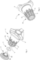
Figure 1 is a rear perspective view of a plurality of elements of a socket-shaft connection assembly intended to be mounted on a pneumatic impact wrench for the motorsport sector; -
Figure 2 is a front perspective and enlarged view of a socket-holding shaft provided between the plurality of elements ofFigure 1 ; -
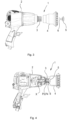
Figure 3 is a side view of a motorsport pneumatic impact wrench wherein an exploded socket-shaft connection assembly is shown; -
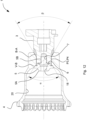
Figure 4 is a longitudinal section of the wrench ofFigure 3 in a configuration wherein the assembly is mounted on the pneumatic impact wrench; -
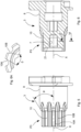
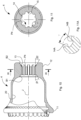
Figure 5 is a side view of the socket-holding shaft ofFigure 2 ; -
Figure 6 is a section ofFigure 5 taken along an axial plane of the socket-holding shaft; - Figure 6A is a partial transversal section of a surface portion of the socket-holding shaft taken along the VI-VI plane of
Figure 6 ; -
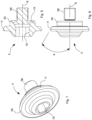
Figure 7 is a front enlarged perspective view of a fixing element provided in the plurality of elements ofFigure 1 ; -
Figure 8 is a side enlarged view of the fixing element ofFigure 7 ; -
Figure 9 is an axial section of the fixing element ofFigure 7 ; -
Figure 10 is a side partially sectioned view of a socket provided in the socket-shaft connection assembly; -
Figure 11 is a section taken along the XI-XI plane ofFigure 10 ; -
Figure 11A is a detail ofFigure 11 ; -
Figure 12 is an axial section of the socket-shaft connection assembly in a connected configuration. - Referring to
Figure 3 andFigure 1 , a socket-shaft connection assembly 1 for motorsportpneumatic impact wrench 2 comprises a socket-holding shaft 3, asocket 4 and afixing element 5 for connecting thesocket 4 to the socket-holding shaft 3 along an axis X of the socket-holding shaft 3. As shown inFigure 1 , aretaining member 6 may be present, for example an O-Ring, which is arranged between thefixing element 5 and the socket-holding shaft 3 when thesocket 4 is mounted on the socket-holding shaft 3. The illustratedsocket 4 is of the type used to screw or unscrew wheel nuts for competition cars, for example Formula 1, fixed to the hub thereof by means of a single central nut, but it can be of a different type, for example for wheels fixed to the hub by means of a plurality of nuts. - The socket-
holding shaft 3 and thesocket 4 comprise respective grooved profiles P3, P4 (Figure 4 ) cooperating for torque transmission between the socket-holding shaft 3 and thesocket 4 when theimpact wrench 2 is in function. - The
fixing element 5 is conformed to exert a force in the direction of the axis X of the socket-holdingshaft 3 to connect thesocket 4 to the socket-holding shaft 3 itself. - The centering of the
socket 4 on the socket-holding shaft 3 occurs by means of a plurality of coupling conical surfaces V-B, B-A (Figure 12 ), obtained respectively on thefixing element 5, on the socket-holding shaft 3 and on thesocket 4. The coupling conical surfaces are distinct from the grooved profiles P3, P4. - Referring to
Figures 2 ,5 and 6 , the socket-holding shaft 3 comprises a drivingend 8 with which it is connected in a known way, thus not herein described, to the shaft of thepneumatic impact wrench 2 by which it is rotated about its own axis X. The socket-holding shaft 3 further comprises a socket-holding end 9, arranged to receive thesocket 4 and on which the grooved profile P3 is obtained. The grooved profile P3 comprises a plurality ofteeth 10, ten in number in the illustrated version, angularly equally spaced on the surface of the socket-holdingend 9. In non-illustrated versions, the number of teeth is other than ten. Eachtooth 10 comprisesflanks tooth base 10, that is closer to axis X, is larger than its tip. A tilt angle δ (delta) between twoflanks Figures 10 and 11 , thesocket 4 comprises a hollow body, having an operatingend 11 by which the car wheel nut is engaged and a connectingend 12 by whichsocket 4 connects with the socket-holding shaft 3. The connectingend 12 comprises ahole 13 into which the socket-holding shaft 3 is fitted and the grooved profile P4, conformed to cooperate with the grooved profile P3 of the socket-holding shaft 3, is obtained on the walls of thehole 13. The grooved profile P4 comprisesgrooves 14, ten in number in the illustrated version, arranged to receiveteeth 10 of the grooved profile P3. Therefore,grooves 14 are angularly equally spaced and define a same number ofprojections 15 alternating withgrooves 14 thereof. The number of grooves can obviously be other than ten.Grooves 14 comprisewalls flanks teeth 10 of the profile P3. The depth ofgrooves 14, i.e. the distance between the bottom of thegroove 14 and the crest of theprojection 15 adjacent to the groove itself, is for instance 4.5 mm with a few tenths of a millimetre tolerance. - Profiles P3 and P4 have resistance sections of the
tooth foot 10 on the socket-holding shaft 3 side and of theprojections 15 on thesocket 4 side that are equal between them. The constant section of the foot of thetooth 10 and of the foot of theprojection 15 allows to have an extremely balanced mounted assembly at rotation. Furthermore, the described geometry allows a more harmonic distribution of tensions resulting in unbalanced deformations not occurring especially on thesocket 4. - When profiles P3 and P4 are coupled, the mutual distance between the flanks of
teeth 10 and the walls of thegrooves 14 is rather low in the order of 0.10-0.20 mm or lower, while the crest ofteeth 10 remains distant from the bottom ofgrooves 14 of about 0.50 mm. Available clearance allows an efficient torque transmission between socket-holding shaft 3 andsocket 4, enabling at the same time to easily remove thesocket 4 from the socket-holding shaft 3, for example, to be replaced. - Referring to
Figure 12 andFigures 6-9 , in order to movably fix thesocket 4 to the socket-holding shaft 3, thefixing element 5 comprises a threadedportion 5B, in form of threaded stem, arranged to engage into a threaded hole 7 (Figure 6 ) obtained in the socket-holdingend 9 of the socket-holding shaft 3. The threadedhole 7 is coaxial with axis X of the socket-holding shaft 3 and comprises a more internal threaded region and astop surface 21 against which thefixing element 5 or the retainingmember 6 can abut once mounted with thesocket 4. Thefixing element 5 further comprises ahead 5A arranged to interact with an inner part of thesocket 4 to restrain thesocket 4 on the socket-holding shaft 3. Thefixing element 5 serves substantially as a screw and the force it exerts in direction of the axis X corresponds to the clamping axial force of thefixing element 5 with which thesocket 4 is constrained once mounted on the socket-holding shaft 3. On thehead 5A the fixingelement 5 has ahollow section 18, for example hexagonal in section, to receive a known clamping tool, for example an Allen key. Anannular recess 19 arranged to receive the retainingmember 6 is provided on thehead 5A in an underhead region of the fixingelement 5. - As indicated above, the torque transmission is implemented by grooved profiles P3 and P4. By contrast the axiality of the
socket 4 with respect to the axis X of the socket-holding shaft is obtained by means of conical couplings. As shown inFigure 12 , a first pair of coupling conical surfaces V-B is provided, one conical surface V of which is provided on thehead 5A of the fixingelement 5, a further conical surface B1 is provided on an inner part 16 of the connectingend 12 of thesocket 4 where thehole 13 ends up in acavity 20 of thesocket 4,such cavity 20 being arranged to house the motorsport nut which must be screwed or unscrewed. In the section view ofFigure 12 , conical surfaces V and B1 of the first pair of coupling conical surfaces V-B have a same vertex angle α (alpha), which is in particular of about 60°, being the vertex arranged in direction of the socket-holdingshaft 3. It is further provided a second pair of coupling conical surfaces B-A, a conical surface B2 of which is obtained on thesocket 4 and a further conical surface A is obtained on the socket-holdingshaft 3 at an inlet aperture 17 of thehole 13. In section view ofFigure 12 , conical surfaces B2 and A of the second pair of coupling conical surfaces B-A have a same vertex angle β (beta), which is in particular equal to vertex angle α (alpha) of the first pair of conical surfaces V-B, for example of about 60°. The vertex of angle β (beta) is arranged in direction ofcavity 20 of thesocket 4. - Centering is obtained by means of the two pairs of conical couplings clamped by means of the fixing
element 5. These conical couplings have no interference and are extremely precise. In fact, the angle ϕ (phi) (Figure 5 ) which, in an axial section the conical surface A of the socket-holdingshaft 3 forms with the axis X, is of 30° with +0.00° to +0.05° tolerance; furthermore, the conical surface A has a linear tolerance of 0.05 mm and a circularity tolerance of 0.05 mm. Similarly, angle β2 (beta2) (Figure 10 ), that the conical surface B2 forms with an axis parallel to the J axis of thesocket 4, is of 30° with -0.00° to -0.05° tolerance; furthermore, the conical surface B2 has a linear tolerance of 0.005 mm and a circularity tolerance of 0.005 mm. Similarly, the angle β1 (beta1) (Figure 10 ) that the conical surface B1 forms with an axis parallel to the J axis of thesocket 4, is of 30° with -0.00° to -0.05° tolerance; furthermore, the conical surface B1 has a linear tolerance of 0.005 mm and a circularity tolerance of 0.005 mm. Similarly, angle ψ (psi) (Figure 8 ) which the conical surface V forms with an axis parallel to the K axis of the fixingelement 5, is of about 30° with +0.0° to +0.5° tolerance; furthermore, the conical surface V has a linear tolerance of 0.005 mm and a circularity tolerance of 0.005 mm. - Centering by means of pairs of conical surfaces substantially allows to reduce an axial clearance to zero, i.e. along axis X, between
socket 4 and socket-holdingshaft 3. - The retaining
member 6 is interposed between the fixingelement 5 and the socket-holdingshaft 3 and is housed in theannular recess 19 and is in contact with astop surface 21 to prevent unscrewing the fixingelement 5 itself and creating a dampening micro-effect. - As indicated above, the configuration of the socket-
shaft connection assembly 1 allows torque transmission by means of grooved profiles P3 and P4 with no centering made therefrom. By contrast, centering is obtained by the conical pairs V-B, B-A when they are clamped by the fixingelement 5. Part of the torsion motion is transmitted by friction also on the centering conical pairs V-B, B-A, thereby relieving grooved profiles P3 and P4 from loads applied onteeth 10 andprotrusions 15 when the high speedpneumatic impact wrench 2 is in function. It must be noted that 10000-12000 rpm of thepneumatic impact wrench 2, corresponding to the free number of revolutions, i.e. with no engagement between socket and nut, becomes of the order of 4000 rpm in the working condition. - Furthermore, the
socket 4 in the working condition is substantially aligned to the ideal axis of the nut to be screwed or unscrewed, this limiting swinging due to eccentricity or tilts with respect to the axis of the socket-holding shaft. This results in a lower rotation radial effect with a more precise engagement of the nut; the pneumatic impact wrench thus becomes more handy. - By significantly reducing swinging of the socket, return stresses on the abutting part of the pneumatic impact wrench are consequently reduced resulting, over time, in a reduced wear if compared to the traditional type of connection with square shaft. In other words, owing to the socket-
shaft connection assembly 1 the working life of the wrench components, as well as that of the socket-holding shaft, has increased. - Furthermore, owing to the socket-
shaft connection assembly 1, mounting thesocket 4 on the socket-holdingshaft 3 is easy and quick. - With respect to the square coupling, the socket-
shaft connection assembly 1 allows to reduce local stresses caused by torsion and to highly distribute them thus resulting in a reduction of local deformations. - The coupling symmetry, wherein the resistant sections on socket and socket-holding shaft are substantially equal, involves a propagation of tensions that is also symmetrical, thereby points of crack initiation are reduced with consequent increase of the average life of the more stressed components.
- It must be noted that during a motorsport pit stop, the wheel nut is screwed in an application time of about 11-15 hundredths of a second and is unscrewed in 9 hundredths of a second, with a nominal working pressure of the supply air of the pneumatic impact wrench of 25 bars; the maximum torque generated by unscrewing is of 4300 Nm, in case of a traditional square coupling.
- Owing to the socket-
shaft connection assembly 1 it is possible to reduce or even overcome problems connected to the use of the square profile in the traditional-type socket-shaft coupling, with reduction of vibrations and swinging of the socket. - Furthermore, experiments show that the socket-
shaft connection assembly 1 allows to obtain an efficient torque transmission and has a high mechanical resistance and to maintain ease of assembling and removal of sockets of traditional systems. - Furthermore, the durability of the assembly components as well as of the pneumatic impact wrench is increased.
- The skilled in the art recognises that the solution of surfaces with grooved profiles for torque transmission distinct from centering coupling conical surfaces, herein described in relation to a single-nut socket, can be adopted even as a solution for socket-shaft coupling for a different type of socket of the motorsport sector.
- In the following, examples of socket-shaft connection assembly are disclosed.
- Example 1: there is provided a socket-shaft connection assembly for motorsport pneumatic impact wrench (2) comprising a socket-holding shaft (3), a socket (4), a fixing element (5) for connecting said socket (4) to said socket-holding shaft (3) along an axis (X) of said socket-holding shaft (3), wherein:
- said socket-holding shaft (3) and said socket (4) comprise respective grooved profiles (P3, P4) cooperating for torque transmission between said socket-holding shaft (3) and said socket (4);
- said fixing element is conformed to exert a force in the direction of the axis of the socket-holding shaft (3) to connect said socket (4) to said socket-holding shaft (3);
- on said fixing element (5), on said socket-holding shaft (3) on said socket (4) a plurality of coupling conical surfaces (V-B, B-A) are obtained for centering said socket (4) on said socket-holding shaft (3), wherein said coupling conical surfaces (V-B, B-A) are distinct from said grooved profiles (P3, P4).
- Example 2: there is provided a socket-shaft connection assembly (1) according to Example 1, wherein said fixing element (5) comprises a threaded portion (5B) arranged to engage in a threaded hole (7) provided in said socket-holding shaft (3) to connect said socket (4) to said socket-holding shaft (3), said threaded hole (7) being aligned with the axis of said socket-holding shaft (3).
- Example 3: there is provided a socket-shaft connection assembly (1) according to Example 2, wherein in an underhead region of the fixing element (5) an annular recess (19) is provided that is arranged to receive a retaining member (6) to maintain said threaded portion (5B) in engagement position with said threaded hole (7).
- Example 4: there is provided a socket-shaft connection assembly (1) according to any one of Examples 1 to 3, wherein said grooved profiles (P3, P4) comprise teeth (10) obtained on said socket-holding shaft (3) and grooves (14) obtained in an inner surface of said socket (4), wherein flanks (10A, 10B) of said teeth (10) and walls (14A, 14B) of said grooves (14) are plane and tilted.
- Example 5: there is provided a socket-shaft connection assembly (1) according to Example 4, wherein a tilt angle (δ (delta)) of said teeth and a tilt angle (γ (gamma)) of said walls are equal to about 24°.
- Example 6: there is provided a socket-shaft connection assembly (1) according to any one of the preceding Examples, wherein said plurality of coupling conical surfaces (V-B, B-A) comprises a first pair of conical surfaces (V, B1) respectively obtained on said socket (4) and on said fixing element (5) and a second pair of conical surfaces (A, B2) respectively obtained on said socket-holding shaft (3) and on said socket (4).
- Example 7: there is provided a socket-shaft connection assembly (1) according to Example 6, wherein with respect to an axial section plane said first pair of conical surfaces (V, B1) has a vertex angle (α (alpha)) equal to a further vertex angle (β (beta)) of said second pair of conical surfaces (B2, A).
- Example 8: there is provided a socket-shaft connection assembly (1) according to Example 7, wherein said vertex angle is of about 30°.
- Example 9: there is provided a socket-shaft connection assembly (1) according to any one of the preceding Examples, wherein said socket (4) is conformed to engage a nut for motorsport single-nut wheels.
- In the following examples of sockets are disclosed.
- According to Example 10, there is provided a motorsport pneumatic impact wrench (2) socket arranged to be connected to a socket-holding shaft (3) of said pneumatic impact wrench (2) along an axis (X), wherein said socket (4) is provided with:
- a grooved profile (P4) arranged to cooperate with a respective grooved profile (P3) of said socket-holding shaft (3) for torque transmission between said socket-holding shaft (3) and said socket (4);
- a connecting end (12) conformed to receive said socket-holding shaft (3) and a fixing element (5) along said axis (X) to connect said socket (4) to said socket-holding shaft (3);
- a first coupling conical surface (B1) arranged to couple with a correspondent conical surface (V) of said fixing element (5) and a second coupling conical surface (B2) arranged to couple with said socket-holding shaft (3) for centering said socket (4), wherein said first coupling conical surface (B1) and said second coupling conical surface (B2) are distinct from said grooved profile (P3).
- Example 11: there is provided a socket (4) according to Example 10, wherein said grooved profile (P4) comprises grooves (14) obtained in an inner surface of said socket (4), wherein walls (14A, 14B) of said grooves (14) are plane and tilted and arranged to interact with flanks (10A, 10B) of teeth (10) obtained on said socket-holding shaft (3).
- Example 12: there is provided a socket (4) according to Example 11, wherein a tilt angle (γ (gamma)) of said walls (14A, 14B) is of about 24°.
- Example 13: there is provided a socket (4) according to Example 11 or Example 12, wherein said grooves (14) are angularly equally spaced on said inner surface.
- Example 14: there is provided a socket (4) according to Example 13, wherein said grooves (14) are ten in number.
- Example 15: there is provided a socket (4) according to any one of Examples 10 to 14, wherein said first and second coupling conical surfaces (B1, B2) have a vertex angle (α (alpha), β (beta)) of about 30°.
Claims (7)
- A socket-holding shaft for motorsport pneumatic impact wrench (2) arranged to receive a socket (4) along an axis thereof (X), characterized in that it is provided with:- a grooved profile (P3) arranged to cooperate with a respective grooved profile (P4) of said socket (4) for torque transmission between said socket-holding shaft (3) and said socket (4);- a socket-holding end (9) conformed to receive a fixing element (5) along said axis (X) to connect said socket (4) to said socket-holding shaft (3);- a coupling conical surface (A) arranged to couple with a correspondent conical surface (B2) on said socket (4) for centering said socket (4), wherein said coupling conical surface (A) is distinct from said grooved profile (P3).
- The socket-holding shaft (3) according to claim 1, wherein said socket-holding end (9) comprises a threaded hole (7) arranged to receive a threaded portion (5B) of said fixing element (5) to connect said socket (4) to said socket-holding shaft (3), said threaded hole (7) being aligned with the axis of said socket-holding shaft (3).
- The socket-holding shaft (3) according to claim 1 or 2, wherein said grooved profile (P3) comprises teeth (10) obtained on said socket-holding shaft (3), wherein flanks (10A, 10B) of said teeth (10) are plane and tilted and arranged to interact with walls (14A, 14B) of grooves (14) obtained in an inner surface of said socket (4).
- The socket-holding shaft (3) according to claim 3, wherein a tilt angle (δ (delta)) of said teeth is equal to about 24°.
- The socket-holding shaft (3) according to claim 3 or 4, wherein said teeth (10) are angularly equally spaced on said socket-holding end (9).
- The socket-holding shaft (3) according to claim 5, wherein said teeth (10) are ten in number.
- The socket-holding shaft (3) according to any one of claims 1 to 6, wherein said coupling conical surface (A) has a vertex angle (β (beta)) of about 30°.
Priority Applications (1)
| Application Number | Priority Date | Filing Date | Title |
|---|---|---|---|
| EP24218776.3A EP4494816A3 (en) | 2019-10-31 | 2019-10-31 | Socket-shaft connection assembly of pneumatic impact wrench |
Applications Claiming Priority (3)
| Application Number | Priority Date | Filing Date | Title |
|---|---|---|---|
| PCT/IB2019/059362 WO2021084315A1 (en) | 2019-10-31 | 2019-10-31 | Socket-shaft connection assembly of pneumatic impact wrench |
| EP19829298.9A EP4051452B1 (en) | 2019-10-31 | 2019-10-31 | Socket-shaft connection assembly of pneumatic impact wrench |
| EP24218776.3A EP4494816A3 (en) | 2019-10-31 | 2019-10-31 | Socket-shaft connection assembly of pneumatic impact wrench |
Related Parent Applications (1)
| Application Number | Title | Priority Date | Filing Date |
|---|---|---|---|
| EP19829298.9A Division EP4051452B1 (en) | 2019-10-31 | 2019-10-31 | Socket-shaft connection assembly of pneumatic impact wrench |
Publications (2)
| Publication Number | Publication Date |
|---|---|
| EP4494816A2 true EP4494816A2 (en) | 2025-01-22 |
| EP4494816A3 EP4494816A3 (en) | 2025-03-26 |
Family
ID=69061404
Family Applications (2)
| Application Number | Title | Priority Date | Filing Date |
|---|---|---|---|
| EP19829298.9A Active EP4051452B1 (en) | 2019-10-31 | 2019-10-31 | Socket-shaft connection assembly of pneumatic impact wrench |
| EP24218776.3A Pending EP4494816A3 (en) | 2019-10-31 | 2019-10-31 | Socket-shaft connection assembly of pneumatic impact wrench |
Family Applications Before (1)
| Application Number | Title | Priority Date | Filing Date |
|---|---|---|---|
| EP19829298.9A Active EP4051452B1 (en) | 2019-10-31 | 2019-10-31 | Socket-shaft connection assembly of pneumatic impact wrench |
Country Status (4)
| Country | Link |
|---|---|
| US (1) | US20230008503A1 (en) |
| EP (2) | EP4051452B1 (en) |
| GB (1) | GB2599612B (en) |
| WO (1) | WO2021084315A1 (en) |
Families Citing this family (1)
| Publication number | Priority date | Publication date | Assignee | Title |
|---|---|---|---|---|
| EP4101594A1 (en) * | 2021-06-09 | 2022-12-14 | Hilti Aktiengesellschaft | Machine tool and method for operating a machine tool |
Family Cites Families (12)
| Publication number | Priority date | Publication date | Assignee | Title |
|---|---|---|---|---|
| US3073192A (en) * | 1957-12-23 | 1963-01-15 | Chicago Pneumatic Tool Co | Splined socket member for wrenches |
| DE59205930D1 (en) * | 1991-03-13 | 1996-05-15 | Polytool Ag | Reamer with exchangeable cutting head |
| US5993186A (en) * | 1997-08-29 | 1999-11-30 | General Electric Company | Single screw extruder |
| US20050160882A1 (en) * | 2004-01-22 | 2005-07-28 | Crow Wesley L. | Variable length socket |
| IL207624A0 (en) * | 2010-08-16 | 2010-12-30 | Iscar Ltd | T-slot cutter |
| DE202011110326U1 (en) * | 2011-09-01 | 2013-07-01 | Hwa Ag | Installation for mounting vehicle wheels |
| AT13498U1 (en) * | 2013-02-22 | 2014-01-15 | Ceratizit Austria Gmbh | milling tool |
| DE102016203188A1 (en) * | 2016-02-29 | 2017-08-31 | Bayerische Motoren Werke Aktiengesellschaft | Shaft-hub-connection |
| US10105768B2 (en) * | 2016-07-05 | 2018-10-23 | Ching-Ting Chen | Cutter holder with vibration resistant structure |
| US10226825B2 (en) * | 2016-11-20 | 2019-03-12 | Charles Michael Berg | Tool holding apparatus |
| AU2019221782A1 (en) * | 2018-02-19 | 2020-10-08 | Milwaukee Electric Tool Corporation | Impact tool |
| CN209207366U (en) * | 2018-03-02 | 2019-08-06 | 力偕实业股份有限公司 | Female drive shafts for power tools |
-
2019
- 2019-10-31 EP EP19829298.9A patent/EP4051452B1/en active Active
- 2019-10-31 WO PCT/IB2019/059362 patent/WO2021084315A1/en not_active Ceased
- 2019-10-31 GB GB2201364.3A patent/GB2599612B/en active Active
- 2019-10-31 EP EP24218776.3A patent/EP4494816A3/en active Pending
- 2019-10-31 US US17/773,205 patent/US20230008503A1/en not_active Abandoned
Also Published As
| Publication number | Publication date |
|---|---|
| EP4051452C0 (en) | 2024-12-11 |
| GB2599612B (en) | 2023-10-11 |
| US20230008503A1 (en) | 2023-01-12 |
| EP4494816A3 (en) | 2025-03-26 |
| WO2021084315A1 (en) | 2021-05-06 |
| EP4051452B1 (en) | 2024-12-11 |
| EP4051452A1 (en) | 2022-09-07 |
| GB2599612A (en) | 2022-04-06 |
Similar Documents
| Publication | Publication Date | Title |
|---|---|---|
| CN105899820B (en) | Threaded element with tool interface | |
| CN104675820B (en) | Grooves and keys for asymmetrical fasteners | |
| JP5839435B2 (en) | Tool holder having a collet holder and tool insert used in the tool holder | |
| US7213999B2 (en) | Fastener with opposite hand threads for securing two components together | |
| CN104349858B (en) | Tool holders for screw-in tools | |
| US5544991A (en) | Locking frustrum nut | |
| US20090304478A1 (en) | Connection element for a screwed connection as well as such a screwed connection | |
| KR102334719B1 (en) | Anti-vibration nut set | |
| US20150298301A1 (en) | Compact Hydraulic Torque Wrench Cartridge | |
| NL8500096A (en) | SCREWS SUITABLE FOR ACCURATE TIGHTENING TORQUES. | |
| KR20140038363A (en) | Force-application means | |
| EP4051452B1 (en) | Socket-shaft connection assembly of pneumatic impact wrench | |
| HK40117475A (en) | Socket-shaft connection assembly of pneumatic impact wrench | |
| CN112567150B (en) | Damping element with threaded portion | |
| US10240640B2 (en) | Shaft-expanding frustoconical lock | |
| US20160311089A1 (en) | Hydraulic Torque Wrench with Stacked Drive Plate Cartridge, Multiple Cartridge Pawls and Snap-in Retract Lock | |
| JP7422368B2 (en) | Deep hole socket drive rod | |
| WO2024047414A1 (en) | Connection unit for mutually connecting two motor-vehicle suspension components | |
| WO2015164548A1 (en) | Hydraulic torque wrench with stacked drive plate cartridge, multiple cartridge pawls and snap-in retract lock | |
| EP3323552A1 (en) | Improved dismounting tool | |
| JP2017520728A (en) | Device for securing a tension element against unintentional release | |
| KR20050020366A (en) | Torque Adaptor | |
| CN217227683U (en) | A length-adjustable steering shaft | |
| CN215201824U (en) | Adapter for mounting bushing | |
| KR200199514Y1 (en) | Shaft Connection Structure of Pump Pump |
Legal Events
| Date | Code | Title | Description |
|---|---|---|---|
| PUAI | Public reference made under article 153(3) epc to a published international application that has entered the european phase |
Free format text: ORIGINAL CODE: 0009012 |
|
| STAA | Information on the status of an ep patent application or granted ep patent |
Free format text: STATUS: THE APPLICATION HAS BEEN PUBLISHED |
|
| AC | Divisional application: reference to earlier application |
Ref document number: 4051452 Country of ref document: EP Kind code of ref document: P |
|
| AK | Designated contracting states |
Kind code of ref document: A2 Designated state(s): AL AT BE BG CH CY CZ DE DK EE ES FI FR GB GR HR HU IE IS IT LI LT LU LV MC MK MT NL NO PL PT RO RS SE SI SK SM TR |
|
| REG | Reference to a national code |
Ref country code: DE Ref legal event code: R079 Free format text: PREVIOUS MAIN CLASS: B25B0021020000 Ipc: B25B0013060000 |
|
| PUAL | Search report despatched |
Free format text: ORIGINAL CODE: 0009013 |
|
| AK | Designated contracting states |
Kind code of ref document: A3 Designated state(s): AL AT BE BG CH CY CZ DE DK EE ES FI FR GB GR HR HU IE IS IT LI LT LU LV MC MK MT NL NO PL PT RO RS SE SI SK SM TR |
|
| RIC1 | Information provided on ipc code assigned before grant |
Ipc: B25B 23/00 20060101ALI20250218BHEP Ipc: B25B 21/02 20060101ALI20250218BHEP Ipc: B60B 29/00 20060101ALI20250218BHEP Ipc: B25B 21/00 20060101ALI20250218BHEP Ipc: B25B 13/06 20060101AFI20250218BHEP |
|
| REG | Reference to a national code |
Ref country code: HK Ref legal event code: DE Ref document number: 40117475 Country of ref document: HK |
|
| STAA | Information on the status of an ep patent application or granted ep patent |
Free format text: STATUS: REQUEST FOR EXAMINATION WAS MADE |
|
| 17P | Request for examination filed |
Effective date: 20250926 |