EP4494573A1 - Cannula with suture lock - Google Patents
Cannula with suture lock Download PDFInfo
- Publication number
- EP4494573A1 EP4494573A1 EP24189119.1A EP24189119A EP4494573A1 EP 4494573 A1 EP4494573 A1 EP 4494573A1 EP 24189119 A EP24189119 A EP 24189119A EP 4494573 A1 EP4494573 A1 EP 4494573A1
- Authority
- EP
- European Patent Office
- Prior art keywords
- suture
- cannula
- elongated body
- securing
- distal end
- Prior art date
- Legal status (The legal status is an assumption and is not a legal conclusion. Google has not performed a legal analysis and makes no representation as to the accuracy of the status listed.)
- Pending
Links
Images






Classifications
-
- A—HUMAN NECESSITIES
- A61—MEDICAL OR VETERINARY SCIENCE; HYGIENE
- A61B—DIAGNOSIS; SURGERY; IDENTIFICATION
- A61B17/00—Surgical instruments, devices or methods
- A61B17/04—Surgical instruments, devices or methods for suturing wounds; Holders or packages for needles or suture materials
- A61B17/0482—Needle or suture guides
-
- A—HUMAN NECESSITIES
- A61—MEDICAL OR VETERINARY SCIENCE; HYGIENE
- A61B—DIAGNOSIS; SURGERY; IDENTIFICATION
- A61B17/00—Surgical instruments, devices or methods
- A61B17/04—Surgical instruments, devices or methods for suturing wounds; Holders or packages for needles or suture materials
- A61B17/06—Needles ; Sutures; Needle-suture combinations; Holders or packages for needles or suture materials
- A61B17/06004—Means for attaching suture to needle
-
- A—HUMAN NECESSITIES
- A61—MEDICAL OR VETERINARY SCIENCE; HYGIENE
- A61B—DIAGNOSIS; SURGERY; IDENTIFICATION
- A61B17/00—Surgical instruments, devices or methods
- A61B17/04—Surgical instruments, devices or methods for suturing wounds; Holders or packages for needles or suture materials
- A61B17/0483—Hand-held instruments for holding sutures
-
- A—HUMAN NECESSITIES
- A61—MEDICAL OR VETERINARY SCIENCE; HYGIENE
- A61B—DIAGNOSIS; SURGERY; IDENTIFICATION
- A61B17/00—Surgical instruments, devices or methods
- A61B17/04—Surgical instruments, devices or methods for suturing wounds; Holders or packages for needles or suture materials
- A61B2017/0496—Surgical instruments, devices or methods for suturing wounds; Holders or packages for needles or suture materials for tensioning sutures
-
- A—HUMAN NECESSITIES
- A61—MEDICAL OR VETERINARY SCIENCE; HYGIENE
- A61B—DIAGNOSIS; SURGERY; IDENTIFICATION
- A61B17/00—Surgical instruments, devices or methods
- A61B17/04—Surgical instruments, devices or methods for suturing wounds; Holders or packages for needles or suture materials
- A61B17/06—Needles ; Sutures; Needle-suture combinations; Holders or packages for needles or suture materials
- A61B17/06004—Means for attaching suture to needle
- A61B2017/06009—Means for attaching suture to needle having additional means for releasably clamping the suture to the needle, e.g. actuating rod slideable within the needle
-
- A—HUMAN NECESSITIES
- A61—MEDICAL OR VETERINARY SCIENCE; HYGIENE
- A61B—DIAGNOSIS; SURGERY; IDENTIFICATION
- A61B17/00—Surgical instruments, devices or methods
- A61B17/04—Surgical instruments, devices or methods for suturing wounds; Holders or packages for needles or suture materials
- A61B17/06—Needles ; Sutures; Needle-suture combinations; Holders or packages for needles or suture materials
- A61B17/06004—Means for attaching suture to needle
- A61B2017/06019—Means for attaching suture to needle by means of a suture-receiving lateral eyelet machined in the needle
-
- A—HUMAN NECESSITIES
- A61—MEDICAL OR VETERINARY SCIENCE; HYGIENE
- A61B—DIAGNOSIS; SURGERY; IDENTIFICATION
- A61B17/00—Surgical instruments, devices or methods
- A61B17/04—Surgical instruments, devices or methods for suturing wounds; Holders or packages for needles or suture materials
- A61B17/06—Needles ; Sutures; Needle-suture combinations; Holders or packages for needles or suture materials
- A61B2017/06052—Needle-suture combinations in which a suture is extending inside a hollow tubular needle, e.g. over the entire length of the needle
-
- A—HUMAN NECESSITIES
- A61—MEDICAL OR VETERINARY SCIENCE; HYGIENE
- A61B—DIAGNOSIS; SURGERY; IDENTIFICATION
- A61B90/00—Instruments, implements or accessories specially adapted for surgery or diagnosis and not covered by any of the groups A61B1/00 - A61B50/00, e.g. for luxation treatment or for protecting wound edges
- A61B90/03—Automatic limiting or abutting means, e.g. for safety
- A61B2090/033—Abutting means, stops, e.g. abutting on tissue or skin
- A61B2090/036—Abutting means, stops, e.g. abutting on tissue or skin abutting on tissue or skin
Definitions
- the present disclosure relates to a cannula, and, more particularly, to systems and methods for passing instruments and traction sutures by way of a cannula.
- Hip arthroscopy also known as hip arthroscopic surgery, is a minimally invasive surgical procedure used to diagnose and treat certain conditions affecting the hip joint. It often involves the use of a specialized instrument called an arthroscope, which is a thin, flexible tube with a camera and light source attached to it. The arthroscope can be inserted into small incisions around the hip joint, allowing the surgeon to visualize and access the internal structures of the joint.
- an arthroscope which is a thin, flexible tube with a camera and light source attached to it. The arthroscope can be inserted into small incisions around the hip joint, allowing the surgeon to visualize and access the internal structures of the joint.
- the surgeon typically creates small incisions around the hip joint to insert the arthroscope and other surgical instruments.
- the hip capsule can then be accessed and often partially or completely released or cut to allow better visualization and access to the internal structures of the joint.
- the surgeon gains increased mobility and maneuverability within the joint, facilitating the examination and treatment of various conditions. This includes addressing labral tears, femoroacetabular impingement (FAI), loose bodies, synovial conditions, and other abnormalities that may be causing pain or limiting hip joint function.
- FAI femoroacetabular impingement
- loose bodies loose bodies
- synovial conditions synovial conditions
- other abnormalities that may be causing pain or limiting hip joint function.
- the hip capsule can interfere with a surgeon's ability to view anatomy during surgical tasks.
- the proposed approach includes a cannula system that combines a cannula with a capsule stitch.
- Embodiments of the proposed approach vary in the way the suture cooperates with the cannula.
- cannula system of this disclosure may include one or more of the following, in any suitable combination.
- the system includes a cannula, including an elongated body having a proximal end, a distal end, and a longitudinal axis extending therebetween, a first surface configured for passage of a surgical instrument along the first surface, and a second surface opposite the first surface.
- a passageway extends along the second surface, which is configured for passage of a suture.
- An eyelet is at least partially defined through the second surface at the distal end of the body for receiving the suture at the distal end.
- the system may further include a proximal securing component defined at the proximal end of the elongated body.
- the proximal securing component includes one or more securing members against the second surface for securing limbs of the suture passed through the passageway and received at the distal end.
- the proximal securing component is configured to secure the limbs of the suture to the elongated body via a knot and/or a cleat.
- the one or more securing members may include two or more wings configured to secure the limbs of the suture to the elongated body via the knot and/or the cleat.
- the proximal securing component may be configured to secure the limbs of the suture to the elongated body via a locking component.
- the locking component includes a foot.
- the locking component is slidably configured along the securing member to further secure the suture.
- the system may further include one or more suture tunnels disposed along the first surface, the one or more suture tunnels configured for passage of limbs of the suture therethrough.
- the locking component may be configured to allow the suture to be adjusted during usage without unsecuring the suture from the securing member.
- the second surface is configured to receive one or more hemostats.
- the one or more hemostats compress the suture and the second surface at an insertion site to create elevation of a tissue, wherein the one or more hemostats are further configured to maintain contact with a patient at an insertion site to further secure the limbs of the suture during use of the cannula.
- a location of the suture at the eyelet is selected to prevent interference with the surgical instrument and/or a surgical implant. In some examples, the location of the suture at the eyelet is more distal to facilitate insertion of the cannula through the insertion site to the tissue. In some examples of the system, the proximal end of the elongated body comprises a textured gripping surface. In some examples, the one or more suture tunnels includes a grooved chamber.
- the proposed approach also includes a method for implementing a surgical procedure.
- the method includes, in part, making an incision on a patient in need of such surgical procedure at a location proximate an operation site to establish an entry portal at an external surgical site.
- the method also includes passing a suture through the surgical site to reach an internal surgical site.
- the method may further include measuring the portal depth from the external surgical site to the internal surgical site.
- the method may also include threading the suture through a cannula to form a cannula system with or without the use of a monofilament to thread a suture through the cannula system.
- the cannula system includes an elongated body having a proximal end, a distal end, and a longitudinal axis extending therebetween, a first surface configured for passage of a surgical instrument along the first surface, and a second surface opposite the first surface.
- the cannula system also includes a passageway extending along the second surface, the passageway configured for passage of the suture.
- the cannula system includes an elongated body having a proximal end, a distal end, and a longitudinal axis extending therebetween, a first surface configured for passage of a surgical instrument along the first surface, and a second surface opposite the first surface.
- the cannula system also includes a passageway extending along the second surface, the passageway configured for passage of the suture.
- the cannula system may further include an eyelet at least partially defined through the second surface at the distal end of the body for passage of the suture through the distal end of the elongated body.
- the cannula system also includes a proximal securing component on the second surface for securing limbs of the suture passed through the passageway and passed around the distal end.
- the method may further include, inserting the cannula system through the external surgical site, cleating the suture to the elongated body, and adjusting the suture against the patient.
- the second surface is configured to receive one or more hemostats.
- One or more hemostats compress the suture and the second surface at an insertion site to create elevation of the tissue, and the one or more hemostats are further configured to maintain contact with a patient at an insertion site to further secure the limbs of the suture during use of the cannula.
- the proximal securing component is configured to secure the limbs of the suture to the elongated body via a locking component.
- the locking component is slidably configured along the second surface to further secure the suture, and the locking component is configured to allow the suture to be adjusted during usage without unsecuring the suture from the securing member.
- the terms “about” and “substantially” represent the inherent degree of uncertainty attributed to any quantitative comparison, value, measurement, or other representation.
- the terms “about” and “substantially” moreover represent the degree by which a quantitative representation may vary from a stated reference without resulting in a change in the basic function of the subject matter at issue.
- Open-ended terms, such as “comprise,” “include,” and/or plural forms of each, include the listed parts and can include additional parts not listed, while terms such as “and/or” include one or more of the listed parts and combinations of the listed parts.
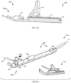
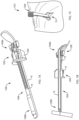
- FIG. 1A illustrates an example of a perspective view of cannula system 100 providing a passageway combining cannula with suture in accordance with this disclosure.
- this system 100 may generally comprise a substantially cylindrical, elongated body 22 having a proximal end 22a and a distal end 22b along a longitudinal axis extending therebetween.
- the elongated body 22, along with others in this disclosure, may resemble a half cylinder, in some implementations, a full cylindrical elongated body is also possible.
- elongated body 22 may angle away from the longitudinal axis at one or both of the proximal end 22a and the distal end 22b to more readily provide an area for a user to manipulate and secure cannula system 100 during use.
- a user can better grasp proximal end 22a during a surgical procedure, which can be seen in Fig. 4D .
- Cannula system 100 may include a first surface 16 configured for passage of a surgical instrument along first surface 16.
- first surface 16 can comprise the underside of cannula system 100, providing access for the passage of surgical instruments and/or implants into a surgical site.
- Cannula system 100 may further include a second surface 18 opposite of first surface 16. Also shown in FIG. 1A , second surface 18 can comprise the topside of cannula system 100.
- One or more passageways 14, which can also be referred to as portals and/or channels, can extend along second surface 18, and in some examples, can be configured to contain and facilitate the passage a suture and/or stitch, such as suture 24, while remaining separate from the passage of instruments along the concavity of first surface 16.
- the second surface 18 may include holes which the suture 24 is fed through and tied off around to secure the suture 24.
- suture 24 can be a traction suture/stitch.
- Suture 24 can be referred to both holistically, and by its limbs, for example.
- one or more securing members 20, which can also be referred to as a proximal securing component, can be disposed on, or in some examples, secured to, components of, the second surface 18 to form passageway 14, secure limbs of the suture 24 as it passes through the passageway 14, and loops around patient tissue at the distal end 22b of elongated body 22.
- cannula system 100 can further include a through hole or eyelet, such as eyelet 10, at the distal end 22b of elongated body 22. While eyelet 10 along with others in this disclosure, may include only a single eyelet in some implementations, additional eyelets are also possible to further provide suture management.
- through eyelet 10 includes a first opening 26a, which can be an oval-shaped eyelet/divot, in second surface 18 at distal end 22b and a second opening 26b at the tip of distal end 22b.
- a first limb of the traction suture 24 passes through tissue at loop 12 during use at a site, such as at patient's hip capsule.
- through eyelet 10 can enclose suture 24 as it is threaded from proximal end 22a of elongated body 22 by way of passageway 14 within one or more suture tunnels 36, before being threaded at loop 12 at distal end 22b around patient tissue before a second limb of traction suture 24 reenters passageway 14 and is threaded back toward proximal end 22a of elongated body 22.
- the suture 24 can then be tied, cleated, wedged, or otherwise secured to provide the desired force/tension throughout cannula system 100.
- suture 24 prior to being secured within cannula system 100, can be placed through the capsule tissue to retract soft-tissue from a surgical location to allow for better viewing during the surgical procedure.
- the suture 24 can then be threaded through the passageway 14 by way of one or more suture tunnels 36 of cannula system 100 to control/manage the suture 24 and keep the suture 24 from interfering with instruments, implants and/or other sutures that may be used in a surgical procedure, before suture 24 can subsequently be secured (for example, via a knot, foot, and/or locking component) by proximal securing component 20 and/or at the site of insertion into a surgical site, such as site 120.
- proximal securing component 20 for example, via a knot, foot, and/or locking component
- FIG. 1B illustrates an example of a perspective view of cannula system 200 providing a passageway/portal 38 for both cannula and suture in accordance with this disclosure.
- Alternate implementations of the proposed approach may vary in the way the suture cooperates with the cannula within a cannula system.
- cannula system 200 is substantially similar to cannula system 100.
- suture 24 can be threaded through the one or more suture tunnels 34 of cannula system 100 to control/manage the suture 24 and keep the suture 24 from interfering with instruments, implants and/or other sutures that may be used in a surgical procedure.
- suture 24 can then be tied, fastened, or otherwise secured to proximal securing component 32 at proximal end 58a of elongated body 58.
- This orientation of cannula system 200 can allow the surgeon to pull/adjust the suture 24 during usage without unsecuring, untying, and/or uncleating the suture 24, which may not be possible in cannula system 100. In some implementations, this will increase displacement of the hip capsule temporarily to gain better temporary visualization for a certain task within the surgery.
- the cannula system 200 can allow the surgeon to use existing channels/passageway/portal, such as portal 38, to create traction on the hip capsule to improve visualization. As a result, the surgeon may not have to create additional incisions to add traction.
- the cannula system's 200 eyelets/channels 38 can thereby manage the traction suture 24 and keep it from interfering with, for example, instruments and implants that may pass through the portal 38 to the surgical site.
- the use of quick suture locking features i.e. cleats
- FIG. 1C illustrates an additional view of cannula system 200.
- suture 24 is visibly secured to proximal securing component 32 of cannula system 200.
- one or more suture tunnels 34 providing a passageway/portal 38 for suture 24 may be individually distinct in form and/or function.
- suture tunnel 40 of one or more suture tunnels 34 operates primarily to enclose and stabilize suture 24 within cannula system 200, much like one or more suture tunnels 20 of cannula system 100, suture tunnels 42 can also provide additional security to suture 24 during usage.
- FIG. 2D This can be seen in another implementation in Fig. 2D , where an external locking component is introduced to compress and initially (as shown in Fig. 2D ) and/or further secure (as shown in Figs. 1B and 1C ) suture 24 during usage.
- Fig. 1C demonstrates the suture 24 threaded through cannula suture tunnels 34 and then tensioned and locked by use of cleat.
- the cleat works in the direction of pulling tension, so that any temporary additional tensioning of the suture 24 can further lock the suture 24 and not "uncleat" the suture during surgery.
- proximal securing component 32 of cannula system 200 can also allow the surgeon to tie the two suture limbs of suture 24 against the respective "nostrils" of the proximal securing component 32, giving the surgeon a second securement option.
- FIG. 2A illustrates an example of an additional cannula system 300 providing a single passageway/portal 50 and including locking component 44.
- cannula systems 100 and 200 alternate implementations of the proposed approach may vary in the way the suture cooperates with the cannula within a cannula system.
- cannula system 300 is substantially similar to cannula systems 100 and 200.
- locking component 44 is slidably configured to further secure suture 24 during use of cannula system 300, similar to the external locking component shown in Fig. 2D .
- Fig. 2D In some examples, such as in Fig.
- locking component 44 is an internal component within cannula system 300, rather than an external component which can be separately introduced as needed, as in Fig. 2D .
- the present example of cannula system 300 also includes one or more suture tunnels 46, which can include suture tunnels 42, which may operate similarly to suture tunnels 42 of cannula system 200 to provide additional security to suture 24 during usage by permitting the introduction of an additional external locking component, as shown in Fig. 2D .
- one or more suture tunnels 46 also can include grooved chamber 48 to facilitate the sliding and securing functionality of locking component 44 within cannula system 300 at proximal end 60a of elongated body 60.
- suture 24 can be readily adjusted and re-secured for tautness and/or slack with additional adjustability, even as suture 24 may be tied, fastened, or otherwise secured to proximal securing component 52 for a baseline level of suture security, similar to the dynamic provided by proximal securing component 32 of cannula system 200 in Fig. 1B and 1C .
- FIGS. 2B and 2C illustrate examples of suture 24 when secured to a proximal securing component of a cannula system, such as proximal securing components 32 and/or 52 of cannula systems 200 and 300, respectively.
- view 325 of Fig. 2B shows suture 24 secured to a proximal securing component of an elongated body of a cannula system via a tie knot. This is similar to how suture 24 is secured in cannula systems 100 and 200, as shown in Figs. 1A-1C .
- FIG. 2C shows suture 24 secured to a proximal securing component of an elongated body of a cannula system via a cleat knot. This is similar to how suture 24 is secured in cannula system 300, as shown in Fig. 2A .
- FIG. 2D illustrates an example of an additional cannula system 400 providing a single portal when engaged with a locking component 54, in before and after perspective views 425 and 450, respectively.
- alternate implementations of the proposed approach may vary in the way the suture cooperates with the cannula within a cannula system.
- cannula system 400 is substantially similar to cannula systems 100, 200, and 300.
- locking component 54 which can also be referred to as a foot, is an external locking component, which can be separately introduced as needed.
- Suture tunnels 56 can be similar to suture tunnels 42 within cannula system 300, as previously introduced in Fig. 2A .
- FIG. 2E illustrates example views 475 and 500 of cannula system 400 of Fig. 2D when engaged with the locking component 54 at different suture depths of 80 and 60 mm, respectively.
- no proximal securing component or additional securing mechanism is present in cannula system 400, by which suture 24 may be secured.
- locking component 54 can be inserted and secured at different depths along suture tunnels 56 to allow for suture 24 to be readily adjusted and re-secured for tautness and/or slack as the means of primary/sole length adjustability.
- locking component 54 can also be used as a foot to provide contact against the skin to better hold suture 24 tension.
- adjusting locking component 54 to the portal depth from skin to the capsule anatomy can be achieved by moving locking component 54 from an 80 mm depth to 60 mm, as shown in view 475 and 500, respectively.
- the locking component 54 can thereby help retain suture 24 tension throughout surgery, while still allowing for the temporary increase in tension by pulling the traction suture 24 ends and cannula system 400 for certain surgical tasks.
- FIG. 2F illustrates example cannula systems 525, 550, and 575, which may be similar to example cannula system 300 of Fig. 2A .
- locking component 44 is shown to be slidably configured to further secure suture 24 (not shown) during use of cannula systems 525, 550, and 575 at their respective and individually varying example cover, grooved chamber, and elongated body portal depths/lengths in order to cover a wide range of patient anatomies.
- respective example suture tunnels, grooved chambers, and elongated bodies of cannula systems 525, 550, and 575 are substantially similar to suture tunnel 42, grooved chamber 48, and elongated body 60 of cannula system 300 of Fig. 2A .
- cannula system 525 which includes an example elongated body 64 measuring approximately 95 mm, includes a locking component 44 which can be adjusted across a 15 mm range along and within grooved chamber 70 to secure suture 24.
- cannula system 550 which includes an example elongated body 66 measuring approximately 120 mm, includes a locking component 44 which can be adjusted across a 20 mm range along and within grooved chamber 72 to secure suture 24.
- cannula system 575 which includes an example elongated body 68 measuring approximately 130 mm, includes a locking component 44 which can be adjusted across a 20 mm range along and within grooved chamber 74 to secure suture 24.
- suture tunnels 76, 78, and 80 which can be substantially similar to suture tunnels 42 of Fig. 2A , measure approximately 70 mm, 90 mm, and 110 mm in cannula systems 525, 550, and 575, respectively.
- FIG. 2G illustrates example view 600 of the cannula systems of Figs. 2A and 2F , with particular focus on the dynamic between locking component 44 and the respective grooved chamber surrounding suture 24.
- View 600 will be referenced to include the components of cannula system 525, however, each component is referred to interchangeably with its substantially similar counterparts in cannula systems 300, 550, and 575.
- locking component 44 is an internal component within cannula systems 525, 550, and 575, rather than an external locking component which can be separately introduced as needed, as in Fig. 2D .
- external locking components are also possible as alternate examples.
- the present example of cannula systems 525, 550, and 575 also includes one or more suture tunnels 46, which can include suture tunnels 42, which may operate similarly to suture tunnels 42 of cannula systems 200 and 300 to provide additional security to suture 24 during usage by permitting the introduction of an additional external locking component, as shown in Fig. 2D .
- one or more suture tunnels 46 also can include grooved chamber 48 to facilitate the sliding and securing functionality of locking component 44 within cannula systems 525, 550, and 575 at proximal ends 64a, 66a, and 68a of elongated bodies 64, 66, and 68, respectively.
- suture 24 can be readily adjusted and re-secured for tautness and/or slack with additional adjustability, even as suture 24 may be tied, fastened, or otherwise secured to proximal securing component 52 for a baseline level of suture security, similar to the dynamic provided by proximal securing component 32 of cannula systems 200 and 300 in previous Figures.
- FIG. 2H illustrates an example of cannula system 700 when engaged with an internal locking component 84.
- cannula systems 100, 200, 300, 525, 550, and 575 alternate implementations of the proposed approach may vary in the way the suture cooperates with the cannula within a cannula system.
- locking component 84 of cannula system 700 is slidably configured to further secure and/or lock suture 24 into a preferred length and/or tautness during use of cannula system 700.
- locking component 84 is an internal component within cannula system 700, rather than an external locking component which can be separately introduced as needed, as in Fig.
- cannula systems 700 also includes one or more suture tunnels 82, which can include suture tunnels 86 and 88, can enclose and stabilize suture 24 within cannula system 700, much like one or more suture tunnels 20 of cannula system 100 or suture tunnels 40 within cannula system 200.
- suture tunnels 82 can include suture tunnels 86 and 88
- suture tunnels 86 and 88 can enclose and stabilize suture 24 within cannula system 700, much like one or more suture tunnels 20 of cannula system 100 or suture tunnels 40 within cannula system 200.
- no additional securing mechanism is present in cannula system 700, by which suture 24 may be secured.
- suture 24 can extend within and through a nexus of locking component 84 and proximal securing component 90 at proximal end 92a of elongated body 92 to permit engagement of suture 24 to be locked/unlocked.
- locking component 84 can be engaged to lock/unlock around suture 24 to provide tension adjustment for tautness and/or slack as the means of primary/sole length adjustability.
- Unlocking suture 24 can also allow for disassembly of cannula system 700. This can allow for more dynamic adjustability of suture 24 length during usage by not requiring initial tying, knotting, or other baseline securing to the cannula system.
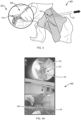
- FIG. 3 illustrates an example 800 of the cannula systems of the present disclosure when engaged in patient treatment, including zoomed-in perspective view 825.
- a traction suture such as suture 24
- suture 24 can then be threaded through the portal/passageway/channel of the cannula system 850, which can include any of those previously discussed, to control/manage the suture 24 and keep the suture 24 from interfering with instruments, implants and/or other sutures which may be used in the procedure.
- suture 24 can be tied, cleated, or wedged to secure the desired tension. Additionally, in some implementations, suture 24 can be further secured by a locking component/foot, such as locking component 54.
- FIGS. 4A-4E provide example photograph views 900-940 illustrating an example process for utilizing the cannula systems of the present disclosure during patient treatment. This example process is similar to that introduced in Fig. 3 .
- view 900 details a user/surgeon passing traction suture 24 through skin site 120 to reach hip capsule 110 during a surgical procedure at surgical treatment site 112.
- views 910 and 915 show the surgeon measuring the portal depth from skin to the capsule 110 with instrument 114, as discussed in Figs. 2E and 2F .
- Fig. 4A details a user/surgeon passing traction suture 24 through skin site 120 to reach hip capsule 110 during a surgical procedure at surgical treatment site 112.
- views 910 and 915 show the surgeon measuring the portal depth from skin to the capsule 110 with instrument 114, as discussed in Figs. 2E and 2F .
- FIG. 4C views 920 and 925 detail threading suture 24 through a cannula body to form a cannula system 116, which can include but are not limited to those introduced previously in the disclosure. Suture 24 may thereby be held taught to provide a straight path for the cannula system 116 at its distal end into the joint via the surgeon's preferred pathway.
- Fig. 4C also shows locking component 118, which may be similar to those introduced in Figs. 2A , 2G , and 2F , along with others. In Fig.
- views 930 and 935 detail inserting the cannula system 116 into the surgical treatment site 112 (not shown), and in some implementations, subsequently adjusting locking component 118 to secure it against the patient's skin at site 120. As previously discussed, this can help retain the tension of suture 24 throughout the surgical procedure, while still allowing for the temporary increase in tension by pulling the traction suture ends at 122 of cannula system 116 for certain surgical tasks, if necessary.
- views 940 and 945 illustrate how once cannula system 116 is sufficiently inserted within site 120 toward surgical site 112 and locking component 118 is secured against site 120, suture 24 can be secured against a proximal securing component 122 of cannula system 116, which may be similar to those introduced. Once the desired tension of suture 24 is achieved around proximal securing component 122, suture 24 can be cleated, wedged, tied, and/or otherwise secured by the surgeon.
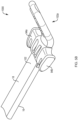
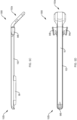
- FIGS. 5A-5E illustrate an example of cannula system 1000.
- cannula systems 100, 200, 300, 525, 550, 575, and 700 alternate implementations of the proposed approach may vary in the way the suture cooperates with the cannula within a cannula system and may utilize processes disclosed in FIGS. 3-4E and 6A-B .
- the proximal end 102 of the body may comprise a textured gripping surface.
- FIG. 5A the proximal end 102 of the body may comprise a textured gripping surface.
- suture 24 can be threaded through the one or more suture tunnels 98 of cannula system 1000 to control/manage the suture 24 and keep the suture 24 from interfering with instruments, implants and/or other sutures that may be used in a surgical procedure along first surface 16.
- Second surface 18 is configured to be engaged by hemostats 136 when cannula system 1000 is compressed against the skin of a patient during a surgical procedure. In some implementations, this creates elevation of a tissue, such as a hip capsule. In system 1000, the length of second surface 18 will be about 35mm between proximal securing component wings 94a and 94b and one or more suture tunnels 98.
- the hemostat may be further configured to maintain contact with the patient at an insertion site to further secure the limbs of the suture 24 during use of the cannula 1000.
- suture 24 can be tied, fastened, or otherwise secured to one or more proximal securing components, including wings 94a and 94b, at proximal end 102a of elongated body 102.
- This orientation of cannula system 1000 can allow the surgeon to pull/adjust the suture 24 during usage without unsecuring, untying, and/or uncleating the suture 24. In some implementations, this will increase displacement of the hip capsule temporarily to gain better temporary visualization for a certain task within the surgery.
- the cannula system 1000 can allow the surgeon to use the secured suture 24 via proximal securing component wings 94 and 94b to create traction on the hip capsule 110 to improve visualization.
- the cannula system's 1000 first and second openings 96a and 96b can thereby manage the traction suture 24 and keep it from interfering with, for example, instruments and implants that may pass through eyelet 10 and one or more suture tunnels 98 to the surgical site at distal end 102b.
- the use of quick suture locking features i.e. cleats
- suture 24 cleats may start with a .006" opening, and taper down to a point.
- This design intent allows for a surgeon to pull one or multiple ⁇ 0.020" suture 24 into the cleat, and have the suture 24 compress within the cleat, such that it locks within a slit of the one or more proximal securing components 94a and 94b.
- This feature should allow suture 24 to be easily pulled in, and then compressed to an amount that achieves the desired suture 24 cleat force requirement within each cannula system.
- One or more monofilaments 99 of the suture 24 can extend from proximal securing components 94a and 94b, as shown in FIG. 5D . These monofilament tail(s) 99 can additionally be pulled and/or engaged to lead traction onto suture 24 of the cannula system 1000 itself during usage.
- a suture such as suture 24
- a suture may be routed through a cannula system via a monofilament.
- the monofilament may be pre-loaded through holes that the capsule suture 24 eventually may pass through.
- tissue such as the hip capsule
- the two tails of the capsule suture 24 are put into a loop(s) of the monofilament(s).
- the tails of the monofilament(s) may then be pulled to shuttle the capsule suture 24 through the cannula system.
- the capsule suture 24 may then preferably be held tight, and then the cannula may be 'ziplined' (by rotating back and forth, as would occur on a zipline) down into the joint space. At this point, positioning of the cannula may be confirmed at the tissue site 110, and the suture 24 may be fixed (cleated) to the proximal end of the cannula.
- FIGS. 6A and 6B illustrate an example process 1100 for utilizing the cannula systems of the present disclosure during patient treatment.
- This example process 1100 is similar to that introduced in FIGs. 3 and 4A-4E .
- cannula system 1000 is referenced.
- Step 126 a surgeon may generally pass one or more traction sutures 24 through the hip capsule 110 to pull it back to improve the view of the surgical site 112.
- Step 128, the desired suture 24 tension of the cannula system 1000 may be set by the surgeon.
- Step 130 provides that a surgeon or other operator of cannula system 1000 may manipulate elongated body 102 to institute a "zipline with twisting motion" to properly secure cannula system 1000 against the surgical site 112.
- Suture 24 may then be cleated via proximal securing component wings 94a and 94b at Step 132 to provide desired tension, while also allowing for monofilament tail(s) 99 to additionally be pulled and/or engaged to lead traction onto suture 24 of the cannula system 1000 to increase tension while remaining cleated.
- suture 24 tension may be held with hemostats 136 at the skin level, or opened and inserted into skin to lock against skin and preserve tension of suture 24 and/or the cannula system 1000.
- hemostat 136 jaws may be introduced to clamp over suture 24 and be behind the cannula 1000, but up against the skin 138 to create internal elevation of capsule 110, as the hemostat compresses skin 138 of patient to do so.
- FIGs. 7A-7C illustrate exemplary cannula system 1200.
- Cannula system 1200 is much like cannula system 1000, and can function according to the processes previously described, including method 1100.
- cannula system 1200 further includes locking component 1202.
- Locking component 1202 functions similarly to previously described locking components.
- the foot 1204 of component 1202 is introduced to cannula system 1200. This foot is engaged with first and second surfaces 18 and 16, and can be adjusted in FIG. 7B to descend from proximal 1206a to distal end 1206b of the elongated body 1206 in order to elevate tissue 110 at site 112 by compressing patient skin, much like hemostat 136 and other disclosed locking components.
- second surface 18 may include teeth, alike to the teeth of systems 300 and 600, to facilitate the movement of locking component 1202.
- FIG. 7C provides view 1210 of this exemplary system 1200 during usage.
Landscapes
- Health & Medical Sciences (AREA)
- Life Sciences & Earth Sciences (AREA)
- Surgery (AREA)
- Heart & Thoracic Surgery (AREA)
- Engineering & Computer Science (AREA)
- Biomedical Technology (AREA)
- Nuclear Medicine, Radiotherapy & Molecular Imaging (AREA)
- Medical Informatics (AREA)
- Molecular Biology (AREA)
- Animal Behavior & Ethology (AREA)
- General Health & Medical Sciences (AREA)
- Public Health (AREA)
- Veterinary Medicine (AREA)
- Surgical Instruments (AREA)
Abstract
A cannula includes an elongated body having a proximal end, a distal end, and a longitudinal axis extending therebetween, a first surface configured for passage of a surgical instrument along the first surface, and a second surface opposite the first surface. A passageway extends along the second surface, which is configured for passage of a suture. An eyelet is at least partially defined through the second surface at the distal end of the body for receiving the suture at the distal end.
Description
- This application claims benefit under 35 U.S.C. § 119 to
U.S. Provisional Application No. 63/528,008, filed on July 20, 2023 - The present disclosure relates to a cannula, and, more particularly, to systems and methods for passing instruments and traction sutures by way of a cannula.
- Hip arthroscopy, also known as hip arthroscopic surgery, is a minimally invasive surgical procedure used to diagnose and treat certain conditions affecting the hip joint. It often involves the use of a specialized instrument called an arthroscope, which is a thin, flexible tube with a camera and light source attached to it. The arthroscope can be inserted into small incisions around the hip joint, allowing the surgeon to visualize and access the internal structures of the joint.
- During hip arthroscopy, the surgeon typically creates small incisions around the hip joint to insert the arthroscope and other surgical instruments. The hip capsule can then be accessed and often partially or completely released or cut to allow better visualization and access to the internal structures of the joint. By releasing or cutting the hip capsule, the surgeon gains increased mobility and maneuverability within the joint, facilitating the examination and treatment of various conditions. This includes addressing labral tears, femoroacetabular impingement (FAI), loose bodies, synovial conditions, and other abnormalities that may be causing pain or limiting hip joint function. However, at times, the hip capsule can interfere with a surgeon's ability to view anatomy during surgical tasks.
- The proposed approach includes a cannula system that combines a cannula with a capsule stitch. Embodiments of the proposed approach vary in the way the suture cooperates with the cannula. Once the incision through the hip capsule is completed, the capsule suture can be placed through the capsule tissue. One may place the capsule stitch in a location that supports traction on the capsule to improve visualization. The suture can then be threaded through the cannula suture eyelets/canals to control/manage the suture and keep the suture from interfering with instruments, implants and/or other sutures used in the procedure. Further, the suture can be tied, cleated or wedged to secure the desired tension.
- Further examples of the cannula system of this disclosure may include one or more of the following, in any suitable combination.
- In examples, the system includes a cannula, including an elongated body having a proximal end, a distal end, and a longitudinal axis extending therebetween, a first surface configured for passage of a surgical instrument along the first surface, and a second surface opposite the first surface. A passageway extends along the second surface, which is configured for passage of a suture. An eyelet is at least partially defined through the second surface at the distal end of the body for receiving the suture at the distal end.
- The system may further include a proximal securing component defined at the proximal end of the elongated body. In some examples, the proximal securing component includes one or more securing members against the second surface for securing limbs of the suture passed through the passageway and received at the distal end. the proximal securing component is configured to secure the limbs of the suture to the elongated body via a knot and/or a cleat. The one or more securing members may include two or more wings configured to secure the limbs of the suture to the elongated body via the knot and/or the cleat.
- In some examples of the system, the proximal securing component may be configured to secure the limbs of the suture to the elongated body via a locking component. In some examples, the locking component includes a foot. In some examples, the locking component is slidably configured along the securing member to further secure the suture.
- In some examples of the system, the system may further include one or more suture tunnels disposed along the first surface, the one or more suture tunnels configured for passage of limbs of the suture therethrough. The locking component may be configured to allow the suture to be adjusted during usage without unsecuring the suture from the securing member. In some examples of the system, the second surface is configured to receive one or more hemostats. In some examples, the one or more hemostats compress the suture and the second surface at an insertion site to create elevation of a tissue, wherein the one or more hemostats are further configured to maintain contact with a patient at an insertion site to further secure the limbs of the suture during use of the cannula.
- In some examples of the system, a location of the suture at the eyelet is selected to prevent interference with the surgical instrument and/or a surgical implant. In some examples, the location of the suture at the eyelet is more distal to facilitate insertion of the cannula through the insertion site to the tissue. In some examples of the system, the proximal end of the elongated body comprises a textured gripping surface. In some examples, the one or more suture tunnels includes a grooved chamber.
- The proposed approach also includes a method for implementing a surgical procedure. The method includes, in part, making an incision on a patient in need of such surgical procedure at a location proximate an operation site to establish an entry portal at an external surgical site. The method also includes passing a suture through the surgical site to reach an internal surgical site. The method may further include measuring the portal depth from the external surgical site to the internal surgical site. The method may also include threading the suture through a cannula to form a cannula system with or without the use of a monofilament to thread a suture through the cannula system. The cannula system includes an elongated body having a proximal end, a distal end, and a longitudinal axis extending therebetween, a first surface configured for passage of a surgical instrument along the first surface, and a second surface opposite the first surface. The cannula system also includes a passageway extending along the second surface, the passageway configured for passage of the suture. The cannula system includes an elongated body having a proximal end, a distal end, and a longitudinal axis extending therebetween, a first surface configured for passage of a surgical instrument along the first surface, and a second surface opposite the first surface. The cannula system also includes a passageway extending along the second surface, the passageway configured for passage of the suture. The cannula system may further include an eyelet at least partially defined through the second surface at the distal end of the body for passage of the suture through the distal end of the elongated body. The cannula system also includes a proximal securing component on the second surface for securing limbs of the suture passed through the passageway and passed around the distal end. The method may further include, inserting the cannula system through the external surgical site, cleating the suture to the elongated body, and adjusting the suture against the patient.
- In examples of the method, the second surface is configured to receive one or more hemostats. One or more hemostats compress the suture and the second surface at an insertion site to create elevation of the tissue, and the one or more hemostats are further configured to maintain contact with a patient at an insertion site to further secure the limbs of the suture during use of the cannula.
- In examples of the method, the proximal securing component is configured to secure the limbs of the suture to the elongated body via a locking component. The locking component is slidably configured along the second surface to further secure the suture, and the locking component is configured to allow the suture to be adjusted during usage without unsecuring the suture from the securing member.
- A reading of the following detailed description and a review of the associated drawings will make apparent the advantages of these and other features. Both the foregoing general description and the following detailed description serve as an explanation only and do not restrict aspects of the disclosure as claimed.
- Reference to the detailed description, combined with the following figures, will make the disclosure more fully understood, wherein:
-
FIG. 1A illustrates an example of a cannula system, in a perspective view; -
FIG. 1B illustrates an example of an additional cannula system, in a perspective view; -
FIG. 1C illustrates an example of the cannula system ofFIG. 1B , in a zoomed- in perspective view; -
FIG. 2A illustrates an example of a third cannula system, in a perspective view; -
FIG. 2B illustrates an example of a suture secured via a tie knot to a cannula system, in a zoomed-in perspective view; -
FIG. 2C illustrates an example of a suture secured via a cleat knot to a cannula system, in a zoomed-in perspective view; -
FIG. 2D illustrates an example of a fourth cannula system, in before and after perspective views; -
FIG. 2E illustrates examples of the cannula system ofFIG. 2D when engaged with a locking component at different suture depths, in a perspective view; -
FIG. 2F illustrates examples of a cannula system similar to that shown inFIG. 2A when engaged with a locking component at different suture depths, in a perspective view; -
FIG. 2G illustrates an example of the dynamic between the locking component and grooved chamber of the cannula systems ofFIGs. 2A and2F , in a zoomed-in perspective view; -
FIG. 2H illustrates an example of a fifth cannula system providing a single tunnel when engaged with an internal locking component, in a perspective view; -
FIG. 3 illustrates an example of the cannula systems of the present disclosure when engaged in patient treatment, in perspective and zoomed-in perspective views; -
FIGs. 4A-4E provide example photographs illustrating an example process for utilizing the cannula systems of the present disclosure during patient treatment; -
FIGs. 5A-5E illustrate an example of an additional cannula system winged proximal securing components, in perspective (FIGS. 5A ,5E ), zoomed-in (FIG. 5B ), side (FIG. 5C ) and bottom (FIG. 5D ) views; -
FIGS. 6A and 6B illustrate an example of the cannula systems of the present disclosure when engaged in patient treatment, in perspective and zoomed-in perspective views; -
FIGs. 7A and 7B illustrate an example of an additional cannula system with a locking component in perspective views; and -
FIG. 7C illustrates an example of the cannula systems of the present disclosure when engaged in patient treatment, in a perspective view. - In the following description, like components have the same reference numerals, regardless of different illustrated examples. To illustrate examples clearly and concisely, the drawings may not necessarily reflect appropriate scale and may have certain features shown in somewhat schematic form. The disclosure may describe and/or illustrate features in one example, and in the same way or in a similar way in one or more other examples, and/or combined with or instead of the features of the other examples.
- In the specification and claims, for the purposes of describing and defining the invention, the terms "about" and "substantially" represent the inherent degree of uncertainty attributed to any quantitative comparison, value, measurement, or other representation. The terms "about" and "substantially" moreover represent the degree by which a quantitative representation may vary from a stated reference without resulting in a change in the basic function of the subject matter at issue. Open-ended terms, such as "comprise," "include," and/or plural forms of each, include the listed parts and can include additional parts not listed, while terms such as "and/or" include one or more of the listed parts and combinations of the listed parts.
-
FIG. 1A illustrates an example of a perspective view ofcannula system 100 providing a passageway combining cannula with suture in accordance with this disclosure. In examples, thissystem 100 may generally comprise a substantially cylindrical,elongated body 22 having aproximal end 22a and adistal end 22b along a longitudinal axis extending therebetween. Although theelongated body 22, along with others in this disclosure, may resemble a half cylinder, in some implementations, a full cylindrical elongated body is also possible. In examples,elongated body 22 may angle away from the longitudinal axis at one or both of theproximal end 22a and thedistal end 22b to more readily provide an area for a user to manipulate andsecure cannula system 100 during use. For example, a user can better graspproximal end 22a during a surgical procedure, which can be seen inFig. 4D .Cannula system 100 may include afirst surface 16 configured for passage of a surgical instrument alongfirst surface 16. Examples of surgical instruments can include, but are not limited to: shavers, burrs, implants, suture management tools, general arthroscopic instruments, trocars, arthroscopic graspers, arthroscopic scissors, arthroscopic dissectors, arthroscopic needle holders, arthroscopic suturing devices, grasping forceps, hook retractors, electrosurgical devices, suction-irrigation systems, and/or sutures. As shown inFIG. 1A ,first surface 16 can comprise the underside ofcannula system 100, providing access for the passage of surgical instruments and/or implants into a surgical site. Examples of surgical instruments can include, but are not limited to: labral anchors, suture anchors, osteochondral plugs, microfracture awls, hip prostheses, bone screws, bone cement.Cannula system 100 may further include asecond surface 18 opposite offirst surface 16. Also shown inFIG. 1A ,second surface 18 can comprise the topside ofcannula system 100. One ormore passageways 14, which can also be referred to as portals and/or channels, can extend alongsecond surface 18, and in some examples, can be configured to contain and facilitate the passage a suture and/or stitch, such assuture 24, while remaining separate from the passage of instruments along the concavity offirst surface 16. Alternatively, thesecond surface 18 may include holes which thesuture 24 is fed through and tied off around to secure thesuture 24. In examples,suture 24 can be a traction suture/stitch.Suture 24 can be referred to both holistically, and by its limbs, for example. - Also shown in
Fig. 1A , one ormore securing members 20, which can also be referred to as a proximal securing component, can be disposed on, or in some examples, secured to, components of, thesecond surface 18 to formpassageway 14, secure limbs of thesuture 24 as it passes through thepassageway 14, and loops around patient tissue at thedistal end 22b ofelongated body 22. To enable this looping around atloop 12,cannula system 100 can further include a through hole or eyelet, such aseyelet 10, at thedistal end 22b ofelongated body 22. Whileeyelet 10 along with others in this disclosure, may include only a single eyelet in some implementations, additional eyelets are also possible to further provide suture management. In examples, througheyelet 10 includes afirst opening 26a, which can be an oval-shaped eyelet/divot, insecond surface 18 atdistal end 22b and asecond opening 26b at the tip ofdistal end 22b. In this way, a first limb of thetraction suture 24 passes through tissue atloop 12 during use at a site, such as at patient's hip capsule. To summarize, througheyelet 10 can enclosesuture 24 as it is threaded fromproximal end 22a ofelongated body 22 by way ofpassageway 14 within one ormore suture tunnels 36, before being threaded atloop 12 atdistal end 22b around patient tissue before a second limb oftraction suture 24 reenterspassageway 14 and is threaded back towardproximal end 22a ofelongated body 22. Thesuture 24 can then be tied, cleated, wedged, or otherwise secured to provide the desired force/tension throughoutcannula system 100. As an illustrative example, during surgery, once an incision through a hip capsule is completed,suture 24, prior to being secured withincannula system 100, can be placed through the capsule tissue to retract soft-tissue from a surgical location to allow for better viewing during the surgical procedure. Thesuture 24 can then be threaded through thepassageway 14 by way of one ormore suture tunnels 36 ofcannula system 100 to control/manage thesuture 24 and keep thesuture 24 from interfering with instruments, implants and/or other sutures that may be used in a surgical procedure, beforesuture 24 can subsequently be secured (for example, via a knot, foot, and/or locking component) byproximal securing component 20 and/or at the site of insertion into a surgical site, such assite 120. This can be seen inFigs. 3-4E , and will be discussed further throughout the disclosure. -
FIG. 1B illustrates an example of a perspective view ofcannula system 200 providing a passageway/portal 38 for both cannula and suture in accordance with this disclosure. Alternate implementations of the proposed approach may vary in the way the suture cooperates with the cannula within a cannula system. For example,cannula system 200 is substantially similar tocannula system 100. However, there may be some structural differences. InFig. 1B , similarly tocannula system 100,suture 24 can be threaded through the one ormore suture tunnels 34 ofcannula system 100 to control/manage thesuture 24 and keep thesuture 24 from interfering with instruments, implants and/or other sutures that may be used in a surgical procedure. However,suture 24 can then be tied, fastened, or otherwise secured toproximal securing component 32 atproximal end 58a ofelongated body 58. This orientation ofcannula system 200 can allow the surgeon to pull/adjust thesuture 24 during usage without unsecuring, untying, and/or uncleating thesuture 24, which may not be possible incannula system 100. In some implementations, this will increase displacement of the hip capsule temporarily to gain better temporary visualization for a certain task within the surgery. For example, thecannula system 200 can allow the surgeon to use existing channels/passageway/portal, such asportal 38, to create traction on the hip capsule to improve visualization. As a result, the surgeon may not have to create additional incisions to add traction. The cannula system's 200 eyelets/channels 38 can thereby manage thetraction suture 24 and keep it from interfering with, for example, instruments and implants that may pass through the portal 38 to the surgical site. In some implementations, the use of quick suture locking features (i.e. cleats) can allow the surgeon to quickly lock, unlock, adjust the tension ofsuture 24 as needed throughout the procedure. -
FIG. 1C illustrates an additional view ofcannula system 200. As shown inFigs. 1B and1C , in some examples,suture 24 is visibly secured toproximal securing component 32 ofcannula system 200. Additionally, and differing fromcannula system 100 ofFig. 1A , one ormore suture tunnels 34 providing a passageway/portal 38 forsuture 24 may be individually distinct in form and/or function. For example, whilesuture tunnel 40 of one ormore suture tunnels 34 operates primarily to enclose and stabilizesuture 24 withincannula system 200, much like one ormore suture tunnels 20 ofcannula system 100,suture tunnels 42 can also provide additional security to suture 24 during usage. This can be seen in another implementation inFig. 2D , where an external locking component is introduced to compress and initially (as shown inFig. 2D ) and/or further secure (as shown inFigs. 1B and1C )suture 24 during usage.Fig. 1C demonstrates thesuture 24 threaded throughcannula suture tunnels 34 and then tensioned and locked by use of cleat. In some implementations, the cleat works in the direction of pulling tension, so that any temporary additional tensioning of thesuture 24 can further lock thesuture 24 and not "uncleat" the suture during surgery. Additionally, the bifurcated "nostril" design ofproximal securing component 32 ofcannula system 200 can also allow the surgeon to tie the two suture limbs ofsuture 24 against the respective "nostrils" of theproximal securing component 32, giving the surgeon a second securement option. -
FIG. 2A illustrates an example of anadditional cannula system 300 providing a single passageway/portal 50 and including lockingcomponent 44. As withcannula systems cannula system 300 is substantially similar tocannula systems component 44 is slidably configured to further securesuture 24 during use ofcannula system 300, similar to the external locking component shown inFig. 2D . In some examples, such as inFig. 2A , lockingcomponent 44 is an internal component withincannula system 300, rather than an external component which can be separately introduced as needed, as inFig. 2D . The present example ofcannula system 300 also includes one ormore suture tunnels 46, which can includesuture tunnels 42, which may operate similarly tosuture tunnels 42 ofcannula system 200 to provide additional security to suture 24 during usage by permitting the introduction of an additional external locking component, as shown inFig. 2D . However, as shown inFig. 2A , one ormore suture tunnels 46 also can include groovedchamber 48 to facilitate the sliding and securing functionality of lockingcomponent 44 withincannula system 300 atproximal end 60a ofelongated body 60. In this way,suture 24 can be readily adjusted and re-secured for tautness and/or slack with additional adjustability, even assuture 24 may be tied, fastened, or otherwise secured toproximal securing component 52 for a baseline level of suture security, similar to the dynamic provided byproximal securing component 32 ofcannula system 200 inFig. 1B and1C . -
FIGS. 2B and 2C illustrate examples ofsuture 24 when secured to a proximal securing component of a cannula system, such as proximal securingcomponents 32 and/or 52 ofcannula systems Fig. 2B showssuture 24 secured to a proximal securing component of an elongated body of a cannula system via a tie knot. This is similar to howsuture 24 is secured incannula systems Figs. 1A-1C . View 350 ofFig. 2C showssuture 24 secured to a proximal securing component of an elongated body of a cannula system via a cleat knot. This is similar to howsuture 24 is secured incannula system 300, as shown inFig. 2A . -
FIG. 2D illustrates an example of anadditional cannula system 400 providing a single portal when engaged with alocking component 54, in before and after perspective views 425 and 450, respectively. As with previous cannula systems, alternate implementations of the proposed approach may vary in the way the suture cooperates with the cannula within a cannula system. For example,cannula system 400 is substantially similar tocannula systems component 54, which can also be referred to as a foot, is an external locking component, which can be separately introduced as needed. As mentioned previously, this process of introduction is detailed in before and after perspective views 425 and 450, respectively, asexternal locking component 54 is introduced and secured into the grooves ofsuture tunnels 56 atproximal end 62a ofelongated body 62.Suture tunnels 56 can be similar tosuture tunnels 42 withincannula system 300, as previously introduced inFig. 2A . -
FIG. 2E illustrates example views 475 and 500 ofcannula system 400 ofFig. 2D when engaged with thelocking component 54 at different suture depths of 80 and 60 mm, respectively. As shown inFigs. 2D and2E , and unlike incannula systems cannula system 400, by which suture 24 may be secured. In this way, lockingcomponent 54 can be inserted and secured at different depths alongsuture tunnels 56 to allow forsuture 24 to be readily adjusted and re-secured for tautness and/or slack as the means of primary/sole length adjustability. This can allow for more dynamic adjustability ofsuture 24 length during usage by not requiring initial tying, knotting, or other baseline securing to the cannula system. Additionally, in some implementations, lockingcomponent 54 can also be used as a foot to provide contact against the skin to better holdsuture 24 tension. For example, inFig. 2E , adjustinglocking component 54 to the portal depth from skin to the capsule anatomy can be achieved by moving lockingcomponent 54 from an 80 mm depth to 60 mm, as shown inview locking component 54 can thereby help retainsuture 24 tension throughout surgery, while still allowing for the temporary increase in tension by pulling thetraction suture 24 ends andcannula system 400 for certain surgical tasks. -
FIG. 2F illustratesexample cannula systems example cannula system 300 ofFig. 2A . InFig. 2F , lockingcomponent 44 is shown to be slidably configured to further secure suture 24 (not shown) during use ofcannula systems cannula systems suture tunnel 42, groovedchamber 48, andelongated body 60 ofcannula system 300 ofFig. 2A . As shown inFig. 2F , in some implementations,cannula system 525, which includes an exampleelongated body 64 measuring approximately 95 mm, includes alocking component 44 which can be adjusted across a 15 mm range along and within groovedchamber 70 to securesuture 24. In some implementations,cannula system 550, which includes an exampleelongated body 66 measuring approximately 120 mm, includes alocking component 44 which can be adjusted across a 20 mm range along and within groovedchamber 72 to securesuture 24. In some implementations,cannula system 575, which includes an exampleelongated body 68 measuring approximately 130 mm, includes alocking component 44 which can be adjusted across a 20 mm range along and within groovedchamber 74 to securesuture 24. Additionally, in some implementations,suture tunnels suture tunnels 42 ofFig. 2A , measure approximately 70 mm, 90 mm, and 110 mm incannula systems -
FIG. 2G illustratesexample view 600 of the cannula systems ofFigs. 2A and2F , with particular focus on the dynamic betweenlocking component 44 and the respective groovedchamber surrounding suture 24. View 600 will be referenced to include the components ofcannula system 525, however, each component is referred to interchangeably with its substantially similar counterparts incannula systems Figs. 2A ,2F , and2G , lockingcomponent 44 is an internal component withincannula systems Fig. 2D . However, external locking components are also possible as alternate examples. The present example ofcannula systems more suture tunnels 46, which can includesuture tunnels 42, which may operate similarly tosuture tunnels 42 ofcannula systems Fig. 2D . However, as shown inFig. 2F , one ormore suture tunnels 46 also can include groovedchamber 48 to facilitate the sliding and securing functionality of lockingcomponent 44 withincannula systems proximal ends elongated bodies suture 24 can be readily adjusted and re-secured for tautness and/or slack with additional adjustability, even assuture 24 may be tied, fastened, or otherwise secured toproximal securing component 52 for a baseline level of suture security, similar to the dynamic provided byproximal securing component 32 ofcannula systems -
FIG. 2H illustrates an example ofcannula system 700 when engaged with aninternal locking component 84. As withcannula systems component 84 ofcannula system 700, as shown inview 725, is slidably configured to further secure and/or locksuture 24 into a preferred length and/or tautness during use ofcannula system 700. As mentioned, in some examples, lockingcomponent 84 is an internal component withincannula system 700, rather than an external locking component which can be separately introduced as needed, as inFig. 2D . However, alternate internal flexible features and/or external locking components are also possible as alternate examples to provide locking/unlocking ofsuture 24. The present example ofcannula systems 700 also includes one ormore suture tunnels 82, which can includesuture tunnels suture 24 withincannula system 700, much like one ormore suture tunnels 20 ofcannula system 100 orsuture tunnels 40 withincannula system 200. Similarly to as shown incannula system 400 inFigs. 2D and2E , and unlike incannula systems cannula system 700, by which suture 24 may be secured. Instead, as shown inview 725,suture 24 can extend within and through a nexus of lockingcomponent 84 andproximal securing component 90 atproximal end 92a ofelongated body 92 to permit engagement ofsuture 24 to be locked/unlocked. In this way, lockingcomponent 84 can be engaged to lock/unlock aroundsuture 24 to provide tension adjustment for tautness and/or slack as the means of primary/sole length adjustability. Unlockingsuture 24 can also allow for disassembly ofcannula system 700. This can allow for more dynamic adjustability ofsuture 24 length during usage by not requiring initial tying, knotting, or other baseline securing to the cannula system. -
FIG. 3 illustrates an example 800 of the cannula systems of the present disclosure when engaged in patient treatment, including zoomed-inperspective view 825. In some implementations, once the initial procedure, such as a capsulotomy (incision through the hip capsule) is completed, a traction suture, such assuture 24, can be placed through the capsule tissue atsurgical site location 110, which can be retracted to improve visualization. Thesuture 24 can then be threaded through the portal/passageway/channel of thecannula system 850, which can include any of those previously discussed, to control/manage thesuture 24 and keep thesuture 24 from interfering with instruments, implants and/or other sutures which may be used in the procedure. Once thesuture 24 is loaded into thecannula system 850, there are multiple means to secure the tension ofsuture 24. For example, thesuture 24 can be tied, cleated, or wedged to secure the desired tension. Additionally, in some implementations,suture 24 can be further secured by a locking component/foot, such as lockingcomponent 54. -
FIGS. 4A-4E provide example photograph views 900-940 illustrating an example process for utilizing the cannula systems of the present disclosure during patient treatment. This example process is similar to that introduced inFig. 3 . InFig. 4A ,view 900 details a user/surgeon passingtraction suture 24 throughskin site 120 to reachhip capsule 110 during a surgical procedure atsurgical treatment site 112. InFig. 4B , views 910 and 915 show the surgeon measuring the portal depth from skin to thecapsule 110 withinstrument 114, as discussed inFigs. 2E and 2F . InFig. 4C , views 920 and 925detail threading suture 24 through a cannula body to form acannula system 116, which can include but are not limited to those introduced previously in the disclosure.Suture 24 may thereby be held taught to provide a straight path for thecannula system 116 at its distal end into the joint via the surgeon's preferred pathway.Fig. 4C also shows lockingcomponent 118, which may be similar to those introduced inFigs. 2A ,2G , and2F , along with others. InFig. 4D , views 930 and 935 detail inserting thecannula system 116 into the surgical treatment site 112 (not shown), and in some implementations, subsequently adjustinglocking component 118 to secure it against the patient's skin atsite 120. As previously discussed, this can help retain the tension ofsuture 24 throughout the surgical procedure, while still allowing for the temporary increase in tension by pulling the traction suture ends at 122 ofcannula system 116 for certain surgical tasks, if necessary. InFig. 4E , views 940 and 945 illustrate how oncecannula system 116 is sufficiently inserted withinsite 120 towardsurgical site 112 andlocking component 118 is secured againstsite 120,suture 24 can be secured against aproximal securing component 122 ofcannula system 116, which may be similar to those introduced. Once the desired tension ofsuture 24 is achieved aroundproximal securing component 122,suture 24 can be cleated, wedged, tied, and/or otherwise secured by the surgeon. -
FIGS. 5A-5E illustrate an example ofcannula system 1000. As withcannula systems FIGS. 3-4E and6A-B . However, there may also be some structural differences. For example, inFIG. 5A , theproximal end 102 of the body may comprise a textured gripping surface. Furthermore, inFIG. 5E , similarly tocannula system 100,suture 24 can be threaded through the one ormore suture tunnels 98 ofcannula system 1000 to control/manage thesuture 24 and keep thesuture 24 from interfering with instruments, implants and/or other sutures that may be used in a surgical procedure alongfirst surface 16.Second surface 18 is configured to be engaged byhemostats 136 whencannula system 1000 is compressed against the skin of a patient during a surgical procedure. In some implementations, this creates elevation of a tissue, such as a hip capsule. Insystem 1000, the length ofsecond surface 18 will be about 35mm between proximal securingcomponent wings more suture tunnels 98. However, there as there are multiple length cannulas, the length of this may vary with the specific cannula system used. The hemostat may be further configured to maintain contact with the patient at an insertion site to further secure the limbs of thesuture 24 during use of thecannula 1000. - As illustrated in
FIGS. 5A-5E ,suture 24 can be tied, fastened, or otherwise secured to one or more proximal securing components, includingwings proximal end 102a ofelongated body 102. This orientation ofcannula system 1000 can allow the surgeon to pull/adjust thesuture 24 during usage without unsecuring, untying, and/or uncleating thesuture 24. In some implementations, this will increase displacement of the hip capsule temporarily to gain better temporary visualization for a certain task within the surgery. For example, thecannula system 1000 can allow the surgeon to use thesecured suture 24 via proximalsecuring component wings 94 and 94b to create traction on thehip capsule 110 to improve visualization. As a result, the surgeon may not have to create additional incisions to add traction. The cannula system's 1000 first andsecond openings traction suture 24 and keep it from interfering with, for example, instruments and implants that may pass througheyelet 10 and one ormore suture tunnels 98 to the surgical site atdistal end 102b. In some implementations, the use of quick suture locking features (i.e. cleats) can allow the surgeon to quickly lock, unlock, adjust the tension ofsuture 24 as needed throughout the procedure. In some implementations,suture 24 cleats may start with a .006" opening, and taper down to a point. This design intent allows for a surgeon to pull one or multiple Ø0.020"suture 24 into the cleat, and have thesuture 24 compress within the cleat, such that it locks within a slit of the one or moreproximal securing components suture 24 to be easily pulled in, and then compressed to an amount that achieves the desiredsuture 24 cleat force requirement within each cannula system. One ormore monofilaments 99 of thesuture 24 can extend fromproximal securing components FIG. 5D . These monofilament tail(s) 99 can additionally be pulled and/or engaged to lead traction ontosuture 24 of thecannula system 1000 itself during usage. - For example, for each of the aforementioned canula systems, a suture, such as
suture 24, may be routed through a cannula system via a monofilament. The monofilament may be pre-loaded through holes that thecapsule suture 24 eventually may pass through. When thecapsule suture 24 is passed through tissue, such as the hip capsule, the two tails of thecapsule suture 24 are put into a loop(s) of the monofilament(s). The tails of the monofilament(s) may then be pulled to shuttle thecapsule suture 24 through the cannula system. Thecapsule suture 24 may then preferably be held tight, and then the cannula may be 'ziplined' (by rotating back and forth, as would occur on a zipline) down into the joint space. At this point, positioning of the cannula may be confirmed at thetissue site 110, and thesuture 24 may be fixed (cleated) to the proximal end of the cannula. -
FIGS. 6A and 6B illustrate an example process 1100 for utilizing the cannula systems of the present disclosure during patient treatment. This example process 1100 is similar to that introduced inFIGs. 3 and4A-4E . For this exemplary process 1100,cannula system 1000 is referenced. InStep 126, a surgeon may generally pass one or more traction sutures 24 through thehip capsule 110 to pull it back to improve the view of thesurgical site 112. AtStep 128, the desiredsuture 24 tension of thecannula system 1000 may be set by the surgeon. Step 130 provides that a surgeon or other operator ofcannula system 1000 may manipulateelongated body 102 to institute a "zipline with twisting motion" to properly securecannula system 1000 against thesurgical site 112.Suture 24 may then be cleated via proximalsecuring component wings Step 132 to provide desired tension, while also allowing for monofilament tail(s) 99 to additionally be pulled and/or engaged to lead traction ontosuture 24 of thecannula system 1000 to increase tension while remaining cleated. AtStep 134,suture 24 tension may be held withhemostats 136 at the skin level, or opened and inserted into skin to lock against skin and preserve tension ofsuture 24 and/or thecannula system 1000. For example,hemostat 136 jaws may be introduced to clamp oversuture 24 and be behind thecannula 1000, but up against the skin 138 to create internal elevation ofcapsule 110, as the hemostat compresses skin 138 of patient to do so. -
FIGs. 7A-7C illustrateexemplary cannula system 1200.Cannula system 1200 is much likecannula system 1000, and can function according to the processes previously described, including method 1100. However,cannula system 1200 further includeslocking component 1202.Locking component 1202 functions similarly to previously described locking components. InFIG. 7A , thefoot 1204 ofcomponent 1202 is introduced tocannula system 1200. This foot is engaged with first andsecond surfaces FIG. 7B to descend from proximal 1206a todistal end 1206b of theelongated body 1206 in order to elevatetissue 110 atsite 112 by compressing patient skin, much likehemostat 136 and other disclosed locking components. Insystem 1200,second surface 18 may include teeth, alike to the teeth ofsystems locking component 1202.FIG. 7C providesview 1210 of thisexemplary system 1200 during usage. - While the disclosure particularly shows and describes preferred examples, those skilled in the art will understand that various changes in form and details may exist without departing from the spirit and scope of the present application as defined by the appended claims. The scope of this present application intends to cover such variations. As such, the foregoing description of examples of the present application does not intend to limit the full scope conveyed by the appended claims.
Claims (20)
- A cannula comprising:an elongated body having a proximal end, a distal end, and a longitudinal axis extending therebetween, a first surface configured for passage of a surgical instrument along the first surface, and a second surface opposite the first surface;a passageway extending along the second surface, the passageway configured for passage of a suture; andan eyelet at least partially defined through the second surface at the distal end of the body for receiving the suture at the distal end.
- The cannula of claim 1, further comprising:
a proximal securing component defined at the proximal end of the elongated body. - The cannula of claim 2, wherein the proximal securing component includes one or more securing members against the second surface for securing limbs of the suture passed through the passageway and received at the distal end.
- The cannula of claim 3, wherein the proximal securing component is configured to secure the limbs of the suture to the elongated body via a knot and/or a cleat.
- The cannula of claim 4, wherein the one or more securing members include two or more wings configured to secure the limbs of the suture to the elongated body via the knot and/or the cleat.
- The cannula of claim 4, wherein the proximal securing component is configured to secure the limbs of the suture to the elongated body via a locking component.
- The cannula of claim 6, wherein the locking component includes a foot.
- The cannula of claim 6, wherein the locking component is slidably configured along the second surface to further secure the suture.
- The cannula of claim 4, further comprising one or more suture tunnels disposed along the first surface, the one or more suture tunnels configured for passage of limbs of the suture therethrough.
- The cannula of claim 8, wherein the locking component is configured to allow the suture to be adjusted during usage without unsecuring the suture from the securing member.
- The cannula of claim 9, wherein the second surface is configured to receive one or more hemostats.
- The cannula of claim 11, wherein the one or more hemostats compress the suture and the second surface at an insertion site to create elevation of a tissue, wherein the one or more hemostats are further configured to maintain contact with a patient at an insertion site to further secure the limbs of the suture during use of the cannula.
- The cannula of claim 12, wherein a location of the suture at the eyelet is selected to prevent interference with the surgical instrument and/or a surgical implant.
- The cannula of claim 14, wherein the location of the suture at the eyelet is more distal to facilitate insertion of the cannula through the insertion site to the tissue.
- The cannula of claim 3, wherein the proximal end of the elongated body comprises a textured gripping surface.
- The cannula of claim 9, wherein the one or more suture tunnels includes a grooved chamber.
- A method for implanting a surgical device, comprising:securing a suture to a tissue in a joint space;threading the suture through a cannula to form a cannula system, the cannula system comprising:an elongated body having a proximal end, a distal end, and a longitudinal axis extending therebetween, a first surface configured for passage of a surgical instrument along the first surface, and a second surface opposite the first surface;a passageway extending along the second surface, the passageway configured for passage of the suture;an eyelet at least partially defined through the second surface at the distal end of the body for passage of the suture through the distal end of the elongated body; andone or more securing members against the second surface for securing limbs of the suture passed through the passageway and passed around the distal end; andmoving the cannula along the suture such that the distal end of the elongated body enters the joint space.
- The method of claim 17, further comprising:inserting the cannula system through the external surgical site;cleating the suture to the elongated body; andadjusting the suture against the patient.
- The method of claim 18, wherein the second surface is configured to receive one or more hemostats,wherein the one or more hemostats compress the suture and the second surface at an insertion site to create elevation of the tissue,wherein the one or more hemostats are further configured to maintain contact with a patient at an insertion site to further secure the limbs of the suture during use of the cannula.
- The method of claim 18, wherein the proximal securing component is configured to secure the limbs of the suture to the elongated body via a locking component,wherein the locking component is slidably configured along the second surface to further secure the suture,wherein the locking component is configured to allow the suture to be adjusted during usage without unsecuring the suture from the securing member.
Applications Claiming Priority (1)
| Application Number | Priority Date | Filing Date | Title |
|---|---|---|---|
| US202363528008P | 2023-07-20 | 2023-07-20 |
Publications (1)
| Publication Number | Publication Date |
|---|---|
| EP4494573A1 true EP4494573A1 (en) | 2025-01-22 |
Family
ID=91958958
Family Applications (1)
| Application Number | Title | Priority Date | Filing Date |
|---|---|---|---|
| EP24189119.1A Pending EP4494573A1 (en) | 2023-07-20 | 2024-07-17 | Cannula with suture lock |
Country Status (2)
| Country | Link |
|---|---|
| US (1) | US20250025154A1 (en) |
| EP (1) | EP4494573A1 (en) |
Citations (3)
| Publication number | Priority date | Publication date | Assignee | Title |
|---|---|---|---|---|
| US20030204196A1 (en) * | 2002-04-24 | 2003-10-30 | Bittar Edward S. | Arthroscopic and endoscopic knot tying device and method of use |
| US20130023929A1 (en) * | 2011-07-22 | 2013-01-24 | Sullivan Derek C | Tensionable knotless acromioclavicular repairs and constructs |
| US20180085109A1 (en) * | 2016-09-26 | 2018-03-29 | Arthrex, Inc. | Cerclage Suture Tensioner and Methods of Tensioning |
Family Cites Families (1)
| Publication number | Priority date | Publication date | Assignee | Title |
|---|---|---|---|---|
| US10182808B2 (en) * | 2015-04-23 | 2019-01-22 | DePuy Synthes Products, Inc. | Knotless suture anchor guide |
-
2024
- 2024-07-17 EP EP24189119.1A patent/EP4494573A1/en active Pending
- 2024-07-19 US US18/777,872 patent/US20250025154A1/en active Pending
Patent Citations (3)
| Publication number | Priority date | Publication date | Assignee | Title |
|---|---|---|---|---|
| US20030204196A1 (en) * | 2002-04-24 | 2003-10-30 | Bittar Edward S. | Arthroscopic and endoscopic knot tying device and method of use |
| US20130023929A1 (en) * | 2011-07-22 | 2013-01-24 | Sullivan Derek C | Tensionable knotless acromioclavicular repairs and constructs |
| US20180085109A1 (en) * | 2016-09-26 | 2018-03-29 | Arthrex, Inc. | Cerclage Suture Tensioner and Methods of Tensioning |
Also Published As
| Publication number | Publication date |
|---|---|
| US20250025154A1 (en) | 2025-01-23 |
Similar Documents
| Publication | Publication Date | Title |
|---|---|---|
| AU2021204456B2 (en) | Transosseous suture anchor | |
| US11684355B2 (en) | Suture anchor | |
| EP2014241B1 (en) | Applicator for suture/button construct | |
| US8821520B2 (en) | Loader for knotting element | |
| US9463008B2 (en) | Multi-loop adjustable knotless anchor assembly, adjustable capture mechanism, and method for repair | |
| EP2710964B1 (en) | Suture leader | |
| US20060241658A1 (en) | Method and apparatus for suture placement | |
| US20260090877A1 (en) | Soft tissue implant systems, instruments and related methods | |
| US10610211B2 (en) | Filament engagement system and methods of use | |
| US20120330357A1 (en) | Multi-loop adjustable knotless anchor assembly and method for repair | |
| US20080188893A1 (en) | Methods and devices for repairing tissue | |
| US10675014B2 (en) | Knotless soft tissue attachment | |
| AU2022230434A1 (en) | Methods and systems related to joint repair | |
| US20250025154A1 (en) | Cannula with suture lock | |
| US10383616B2 (en) | Methods for attaching soft tissue to bone | |
| AU2006240354B2 (en) | Method and apparatus for suture placement |
Legal Events
| Date | Code | Title | Description |
|---|---|---|---|
| PUAI | Public reference made under article 153(3) epc to a published international application that has entered the european phase |
Free format text: ORIGINAL CODE: 0009012 |
|
| STAA | Information on the status of an ep patent application or granted ep patent |
Free format text: STATUS: THE APPLICATION HAS BEEN PUBLISHED |
|
| AK | Designated contracting states |
Kind code of ref document: A1 Designated state(s): AL AT BE BG CH CY CZ DE DK EE ES FI FR GB GR HR HU IE IS IT LI LT LU LV MC ME MK MT NL NO PL PT RO RS SE SI SK SM TR |
|
| STAA | Information on the status of an ep patent application or granted ep patent |
Free format text: STATUS: REQUEST FOR EXAMINATION WAS MADE |
|
| 17P | Request for examination filed |
Effective date: 20250722 |
|
| STAA | Information on the status of an ep patent application or granted ep patent |
Free format text: STATUS: EXAMINATION IS IN PROGRESS |