EP4494538A1 - Silencing air duct device, air duct assembly, and cleaning robot - Google Patents
Silencing air duct device, air duct assembly, and cleaning robot Download PDFInfo
- Publication number
- EP4494538A1 EP4494538A1 EP23769840.2A EP23769840A EP4494538A1 EP 4494538 A1 EP4494538 A1 EP 4494538A1 EP 23769840 A EP23769840 A EP 23769840A EP 4494538 A1 EP4494538 A1 EP 4494538A1
- Authority
- EP
- European Patent Office
- Prior art keywords
- diversion
- air
- airflow
- channel
- air duct
- Prior art date
- Legal status (The legal status is an assumption and is not a legal conclusion. Google has not performed a legal analysis and makes no representation as to the accuracy of the status listed.)
- Pending
Links
Images





Classifications
-
- A—HUMAN NECESSITIES
- A47—FURNITURE; DOMESTIC ARTICLES OR APPLIANCES; COFFEE MILLS; SPICE MILLS; SUCTION CLEANERS IN GENERAL
- A47L—DOMESTIC WASHING OR CLEANING; SUCTION CLEANERS IN GENERAL
- A47L7/00—Suction cleaners adapted for additional purposes; Tables with suction openings for cleaning purposes; Containers for cleaning articles by suction; Suction cleaners adapted to cleaning of brushes; Suction cleaners adapted to taking-up liquids
- A47L7/04—Suction cleaners adapted for additional purposes; Tables with suction openings for cleaning purposes; Containers for cleaning articles by suction; Suction cleaners adapted to cleaning of brushes; Suction cleaners adapted to taking-up liquids for using the exhaust air for other purposes, e.g. for distribution of chemicals in a room, for sterilisation of the air
-
- A—HUMAN NECESSITIES
- A47—FURNITURE; DOMESTIC ARTICLES OR APPLIANCES; COFFEE MILLS; SPICE MILLS; SUCTION CLEANERS IN GENERAL
- A47L—DOMESTIC WASHING OR CLEANING; SUCTION CLEANERS IN GENERAL
- A47L9/00—Details or accessories of suction cleaners, e.g. mechanical means for controlling the suction or for effecting pulsating action; Storing devices specially adapted to suction cleaners or parts thereof; Carrying-vehicles specially adapted for suction cleaners
- A47L9/0081—Means for exhaust-air diffusion; Means for sound or vibration damping
-
- A—HUMAN NECESSITIES
- A47—FURNITURE; DOMESTIC ARTICLES OR APPLIANCES; COFFEE MILLS; SPICE MILLS; SUCTION CLEANERS IN GENERAL
- A47L—DOMESTIC WASHING OR CLEANING; SUCTION CLEANERS IN GENERAL
- A47L2201/00—Robotic cleaning machines, i.e. with automatic control of the travelling movement or the cleaning operation
Definitions
- the present disclosure relates to the field of air purification, and in particular to a muffling air duct device, an air duct component, and a cleaning robot.
- the existing cleaning equipment such as vacuum cleaners, intelligent cleaning robots, etc., all have functions such as vacuuming and dust removal.
- the working principle of their vacuuming function is to use an electric motor to drive blades for rotation at high speed, thereby generating negative air pressure inside the sealed housing and sucking up dust from the ground or the required cleaning position.
- the high-speed airflow generated by the motor will rub against other air and equipment components, resulting in significant noise in the air duct system of the cleaning equipment during suction and dust removal.
- the noise not only affects the user experience of using the corresponding cleaning equipment products, but also the vibration generated by the friction between the air also affects the stability of the cleaning equipment during use, which to some extent affects the cleaning effect of the equipment.
- the purpose of the present disclosure is to provide a muffling air duct device, an air duct component, and a cleaning robot that solves a technical problem of excessive noise in a working state of cleaning equipment while ensuring the efficiency of the cleaning equipment.
- the present disclosure adopts the following technical solutions.
- a muffling air duct device which includes:
- an air duct component which includes:
- a cleaning robot which includes:
- the beneficial effects of the present disclosure are: in the muffling air duct device, the inlet direction and the outlet direction of the airflow channel are at least partially offset from each other, thereby extending the length of the airflow path in the airflow channel.
- collisions occur in the airflow channel, causing energy loss and reducing airflow velocity, achieving preliminary muffling effect; multi-stage diversion components, being installed in the airflow channel, each stage of diversion components dividing the airflow channel into several diversion channels, further extending a path length inside the airflow channel, the diversion body performing diverting processing on the airflow to allow multiple secondary airflows separated from the main airflow to enter each diversion channel separately.
- each stage of diversion component can further divert the airflow, indirectly increasing a contact area between the air and each diversion bodies and the length of the airflow path. This allows sound waves to be more fully absorbed and muffled in the airflow channel, and can also avoid the situation where the airflow is discharged through the shortest path in the airflow channel. Without increasing the size of the equipment and air duct, it is ensured that the air resistance parameters in the airflow channel meet working requirements of the cleaning equipment, while improving the muffling effect.
- connection and “fixed” should be broadly understood, for example, it may be fixed connections, detachable connections, or integrated; or it may be a mechanical connection or an electrical connection; or it may be directly connected or indirectly connected through an intermediate medium; or it may be a connection within two components or an interaction relationship between two components.
- connection and “fixed” should be broadly understood, for example, it may be fixed connections, detachable connections, or integrated; or it may be a mechanical connection or an electrical connection; or it may be directly connected or indirectly connected through an intermediate medium; or it may be a connection within two components or an interaction relationship between two components.
- a first feature “above” or “below” a second feature may include direct contact between the first and second features, or may include contact between the first and second features through another feature between them instead of direct contact.
- the first feature being “above”, “over”, and “on” the second feature includes the first feature being directly above and diagonally above the second feature, or simply indicating that the first feature is horizontally higher than the second feature.
- the first feature being “below”, “underneath”, and “under” includes the first feature being directly below and diagonally below the second feature, or simply indicating that the first feature is horizontally lower than the second feature.
- the embodiment of the present disclosure provides a muffling air duct device
- the muffling air duct device is mainly used in cleaning equipment.
- the muffling air duct device reduces the exhaust noise of cleaning equipment, such as cleaning robots, by adding multi-stage diversion components 20 in an airflow channel 10.
- This muffling air duct device is suitable for the characteristics of small installation space and high space utilization required inside cleaning robots.
- this embodiment provides a cleaning robot, and the cleaning robot is an intelligent household appliance, also known as an automatic cleaning machine, intelligent vacuum robot, vacuum cleaner, etc. It is a type of intelligent household appliance that may automatically complete cleaning work in its region with certain artificial intelligence.
- Cleaning robots generally use brushing and vacuum manners to first absorb floor dust into their own dust collection box 70, thereby completing the function of floor cleaning.
- the cleaning robot is operated remotely using a remote control or through the control panel on the body, which is mainly disc-shaped. Using rechargeable batteries for operation, it is generally possible to set a time to schedule cleaning and self-charge. There are sensors installed in front that may detect obstacles.
- the cleaning robot generates noise during the operation of the fan, which affects the usage of the user and also has a certain impact on the physical health of the user.
- FIG. 16 it is a schematic diagram of a partial structure of a cleaning robot applied to the muffling air duct device in this embodiment.
- the cleaning robot generally has an outer shell (not shown in the figure) and a base component arranged inside the outer shell.
- the base component includes a base body 60, and by setting driving wheels, batteries, air duct components and other components on the base body 60, the cleaning robot described in this embodiment is assembled.
- the outer shell may play a role in protecting the components in the base assembly of the cleaning robot.
- a corresponding avoidance space may be opened at an air outlet 12 of the muffling air duct device on the outer shell, providing air blown out from the air outlet 12 to be discharged outside the outer shell.
- the above-mentioned dust collection box 70 is used for temporary storage of dust and garbage collected by the cleaning robot.
- the dust collection box 70 may be installed on the outer shell of the cleaning robot through a detachable installation manner, or fixed relative to the outer shell. By arranging a dust outlet, users may clean the collected materials inside in a manner of automatic dust exhaust through the workstation or a manner of manual dust exhaust.
- the dust collection box 70 may be equipped with a dust inlet and an exhaust outlet.
- the dust inlet may be connected to a dust suction channel (not shown) on the bottom body of the cleaning robot.
- a dust suction part is formed on the dust suction channel that is connected to the outside of the cleaning robot. When the cleaning robot is in use, the dust suction part is facing the floor to be cleaned by the cleaning robot.
- the other side of the dust suction part is connected to the inlet airflow channel 321 of the muffling air duct device through the dust suction channel, the dust collection box 70, and an exhaust duct 52 of a fan 50.
- the exhaust outlet of the dust collection box 70 is used to connect with the draft duct 51 of the fan 50.
- the fan 50 is a main power output component of the air duct assembly in the cleaning robot. The fan 50 is used to provide power and create negative pressure in the dust suction channel, thereby sucking dust from the ground into the dust collection box 70.
- this embodiment is applied to the air duct component of the cleaning robot.
- the fan 50 according to this embodiment is a component that converts input electrical energy into mechanical energy, thereby increasing gas pressure and delivering gas.
- the fan 50 according to this embodiment has a draft duct 51 and an exhaust duct 52.
- the draft duct 51 may be arranged at the top or bottom of the fan 50, and the exhaust duct 52 may be arranged at the side of the fan 50. This can effectively utilize the internal space of the cleaning robot, and the fan 50 can also have better air force effect.
- a shock-absorbing hose 53 is arragned between the exhaust duct 52 and the muffling air duct device.
- the shock-absorbing hose 53 is made of a material with shock-absorbing function, which may be made of soft materials such as soft rubber.
- the shock-absorbing hose 53 can reduce the noise at the exhaust duct 52 of the fan 50 through shock-absorbing, and also improve the airtightness between the fan 50 and the muffling air duct device, ensuring the stability of air flow and thereby improving the reliability of the air duct component.
- the fan 50 includes a housing and an air supply component arranged inside the housing.
- a space for air flow is formed between the housing and the air supply component, and the space is connected to the external environment of the housing through the draft duct 51 and the exhaust duct 52, respectively.
- the housing can protect the air supply components and prevent airflow leakage.
- the exhaust duct 52 is tangent to the rotation direction of the air supply components, making the airflow inside the fan 50 smoother and increasing the air supply efficiency of the fan 50.
- the muffling air duct device of this embodiment includes an airflow channel 10, and the airflow channel 10 provides a gas discharge channel space for the cleaning equipment during the dust suction process, thereby restricting the direction of gas flow discharged by the fan 50.
- the two ends of the airflow channel 10 are respectively equipped with an air inlet 11 and an air outlet 12 that are connected to the external environment.
- the air inlet 11 is used to communicate with the exhaust duct 52 of the fan 50, and the gas discharged from the exhaust duct 52 may be discharged from the air outlet 12 through the airflow channel 10 to the outside of the cleaning robot.
- the air inlet 11 and the air outlet 12 are respectively used to restrict the inlet and outlet directions of the airflow channel 10.
- the inlet and outlet directions are at least partially offset from each other, and the offset between the inlet and outlet directions may be understood as the fact that the inlet and outlet directions are at least partially facing in different directions. It may also be understood that even if they are in the same direction, the inlet and outlet directions may be offset on the same horizontal plane or on different horizontal planes.
- the inlet and outlet directions are also at least partially offset in two positions, so that at least some of the airflow path in the airflow channel 10 may have disturbance structure such as bent, curved, or other ways that may disrupt the flow airflow direction.
- multi-stage diversion components 20 are sequentially set up.
- Each stage of diversion components 20 divides the airflow channel 10 into several diversion channels 22.
- the main airflow entering the airflow channel 10 from the air inlet 11 may be diverted by the diversion channels 22, thus forming a secondary airflow.
- the secondary airflow is guided by the diversion channels 22, changing the flow direction and extending the airflow path of the secondary airflow.
- Each secondary airflow will experience energy loss during the process of changing the flow direction, reducing the flow velocity of each secondary airflow.
- Corresponding muffling may be arranged in the diversion channels 22.
- the structure is such that the sound waves of the secondary airflow are buffered and absorbed within the diversion channel 22,
- the diversion channels 22 formed by each stage of diversion are communicated, allowing each secondary airflow to re-merge near the air outlet 12 and be discharged from the muffling duct device.
- the structure and muffling design of the diversion channel 22 need to ensure that the air resistance parameters meet the requirements of the cleaning robot during operation, and that the flow of each secondary airflow in the diversion channel 22 is smooth, so that the negative pressure formed at the draft duct 51 of the fan 50 in the application of the cleaning equipment is sufficient to suck in dust at the suction part.
- the diversion component 20 includes at least one diversion body 21, each diversion body 21 separating the airflow channel 10 into at least two diversion channels 22, thereby playing a role in diffusing, disturbing, and guiding the airflow with sound waves.
- the secondary airflow enters the corresponding diversion channel 22 its sound waves undergo multiple and repeated contact friction with the muffling structure arranged in the diversion channel 22, allowing the sound waves to be absorbed in the diversion channel 22 or resonate with the diversion body 21 when contact friction occurs with the diversion body 21, thereby consuming and absorbing the sound waves of the secondary airflow.
- the later stage of diversion body 21 is arranged at one of the diversion channels 22 separated by the former stage of diversion body 21. It may be understood that the main airflow entering the airflow channel 10 from the air inlet 11 is diverted by the diversion body 21 in the first stage of diversion component 20 closest to the air inlet 11 to form at least two secondary airflows.
- the secondary airflows flow in the diversion channels 22 separated by the first stage of diversion component 20 and undergo muffling treatment. Each secondary airflow will be guided by the corresponding diversion channel 22 to the later stage of diversion component 20.
- At least one secondary airflow will be further diverted, disturbed at the second stage of diversion body 21, and further diverted secondary airflow flows into the subsequent diversion channel 22 for further muffling treatment.
- multiple levels of branches of diversion channels 22 are formed within the airflow channel 10.
- the sound waves in the airflow are continuously diverted and disturbed before being subjected to muffling treatment, and then diverted and disturbed again, fully increasing the contact area between each airflow and the diversion body 21 and the muffling structure.
- the sound waves are buffered by each diversion channel 22, allowing the majority of their energy to be consumed within the diversion channel 22, thereby effectively improving the muffling effect of the muffling air duct device on the sound waves in the airflow.
- At least one side wall of the diversion channel 22 is formed through the side of the diversion body 21, and the other side wall of the diversion channel 22 may be determined based on the structure located on the side of the diversion body 21.
- any two adjacent diversion bodies 21 in the same stage of the diversion component 20 are arranged opposite to each other.
- two diversion channels 22 are formed from the perspective of airflow, and these two diversion channels 22 will eventually merge.
- the side walls of these two diversion channels 22 are respectively formed by two adjacent diversion bodies 21.
- the number of diversion bodies 21 in the same stage of the diversion component 20 is one, and a diversion channel 22 is formed between the side of the diversion body 21 and the inner wall of the muffling duct device; or when the number of diversion bodies 21 in the same level diversion component 20 is greater than or equal to two, a diversion channel 22 is formed between the side of the diversion body 21 closest to the inner wall of the muffling duct device and the inner wall of the muffling duct device.
- each secondary airflow may be guided to flow between the inner wall of the muffling duct device and the diversion body 21, as well as in the diversion channel 22 formed between each diversion body 21.
- a partition may be arranged between any two adjacent diversion bodies 21 of the same stage of diversion component 20, and a partition may be arranged between the diversion bodies 21 and the inner wall of the muffling air duct device, forming a diversion channel 22 through the partition and the side of the diversion bodies 21.
- the first stage of diversion component 20 closest to the air inlet 11 includes a diversion body 21, and the second stage of diversion component 20 after the first stage of diversion component 20 includes two diversion bodies 21.
- the diversion bodies 21 in the second stage of diversion component 20 are respectively arranged on the paths of two diversion channels 22 formed by the diversion body 21 of the first stage of diversion component 20. In this way, the main airflow entering from the air inlet 11 will be separated by the diversion body 21 located in the first stage of diversion component 20 to form two secondary airflows.
- the two secondary airflows will flow along the diversion channels 22 formed on both sides of the first stage of diversion body 21, respectively, towards the two diversion bodies 21 located in the second stage of diversion component 20. Subsequently, when the secondary airflows respectively come into contact with the second stage of diversion body 21, they will be separated into two secondary airflows, ultimately forming at least four secondary airflows. When the airflows are not separated once, their flow direction, velocity, and flow rate will change, thereby improving the contact area between each diversion channel 22 and its internal gas, effectively enhancing the sound wave muffling effect.
- the second stage of diversion component 20, the third stage of diversion component 20, and the subsequent stage of diversion components 20 are the diversion components 20 arranged in sequence along the airflow direction of the airflow channel 10 in each stage of diversion region.
- the former stage diversion component 20 refers to the diversion component 20 that is relatively located in the diversion region close to the air inlet 11
- the second stage of diversion component 20 refers to the diversion component 20 that is relatively located in the diversion region close to the air outlet 12.
- the air supply component Due to the small diameter of exhaust duct 52, the air supply component generates a large air pressure inside the housing of the fan 50 during rotation. Therefore, when high-pressure air is discharged from exhaust duct 52, it will cause impact vibration on the external air, resulting in noise. Therefore, the faster the speed of the air supply component and the higher the air pressure inside exhaust duct 52, the greater the noise generated by the fan 50 during the exhaust process.
- the size of the airflow channel 10 needs to be larger than that of the exhaust duct 52, providing sufficient buffer space for the discharged airflow, so that the noise can be buffered and absorbed in the muffling duct device.
- the diversion body 21 includes an air ward part 211 and an air guide part 212.
- the air ward part 211 and the air guide part 212 may be integrated into a single molding structure to reduce the processing and installation difficulties of the diversion body 21.
- the air ward part 211 and the air guide part 212 may also be two independent components that are coupled to each other in the air path structure formed by them, and are arranged in the airflow channel 10 through independent processing, installation, and other manners.
- the air ward part 211 is arranged at an end of the diversion body 21 close to the air inlet 11, used to separate the airflow channel 10 into at least two alternating diversion channels 22.
- the air ward part 211 is a part where the diversion body 21 first comes into contact with the airflow.
- the air ward part 211 will block the airflow, change the airflow direction, and divide the airflow into at least two channels, each of divided airflow will flow into the corresponding diversion channel 22.
- Each of air guide parts 212 forms one side wall of its corresponding diversion channel 22, and the air guide part 212 is used to guide the airflow direction in its corresponding diversion channel 22.
- the airflow path formed by the separation of each air guide part 212 and the air ward part 211 is consistent, so that all the airflow diverted by the air ward part 211 can be guided by the air guide part 212, and the buffering and absorption effect of noise and sound waves in the airflow can also be improved.
- the distance between any two adjacent air guide parts 212 is greater than or equal to that of the air ward parts 211, thereby forming a diffusive structure of diversion channels 22, providing sufficient installation space for the later stage of diversion body 21 and sufficient flow space for the air in the first stage.
- the air ward part 211 includes a first diversion surface 2111 and a second diversion surface 2112 arranged at an angle.
- the first diversion surface 2111 and the second diversion surface 2112 are used to separate the airflow channel 10 to form a diversion channel 22.
- An end of the first diversion surface 2111 is connected with that of the second diversion surface 2112, and the first diversion surface 2111 and the second diversion surface 2112 may gradually extend in the direction away from each other and towards the air outlet 12. It may be understood that, as shown in Fig.
- each of air guide parts 212 includes an air guide surface 2121.
- An end of the air guide surface 2121 is connected to the first diversion surface 2111 or the second diversion surface 2112, and the other end of the air guide surface 2121 extends along the airflow direction of the corresponding diversion channel 22.
- the air guide surface 2121 includes a first guide surface and a second guide surface. An end of the first guide surface is connected to the first diversion surface 2111, and an end of the second guide surface is connected to the second diversion surface 2112.
- first guide surface and the second guide surface are facing away from each other and extend towards the direction of the air outlet 12. It should be noted that the airflow path formed by the first diversion surface 2111 is coupled with the airflow path of the first guide surface, and the airflow path formed by the second diversion surface 2112 is coupled with the airflow path of the second guide surface.
- each air guide surface 2121 gradually increases from the end close to the air ward part 211 to the end far away from the air ward part 211.
- the space between them gradually increases to form a diffusive structure, providing sufficient installation space for the later stage of diversion body 21 and sufficient airflow space for the later stage of diversion channel 22.
- peripheral shape of the diversion body 21 includes but is not limited to a combination of one or more of droplet shape, circle, diamond shape, and rectangle.
- the above description of the structure of the diversion body 21 is applicable to cases where the periphery of the diversion body 21 has irregular shapes such as water droplets, diamonds, rectangles, etc.
- the shape of the periphery of the diversion body 21 adopts a water droplet structure.
- the air ward part 211 may also be a plane, as long as it may achieve the effect of diverting airflow.
- first channel 13 and second channel 14 formed in the airflow channel 10.
- the air inlet 11 is correspondingly connected to the first channel 13, and the air outlet 12 is correspondingly connected to the second channel 14.
- the number of diversion components 20 is greater than 2.
- the number of diversion bodies 21 of each stage of diversion components 20 in the first channel 13 increases stage by stage in the airflow direction, and the number of diversion bodies 21 of each stage of diversion components 20 in the second channel 14 decreases stage by stage in the airflow direction.
- the main airflow is separated into multiple secondary airflows after entering the airflow channel 10, and the multiple secondary airflows may merge into one airflow and be discharged from the air outlet 12 when approaching the air outlet 12.
- the muffling requirements of the air duct device are met, and the volume of the air duct device gradually increases from the air inlet 11 to the air outlet 12 and then gradually decreases, minimizing the overall volume of the air duct device and meeting the installation needs of the cleaning robot.
- the airflow channel 10 is sequentially equipped with multi-stage diversion regions along the airflow direction, and each of the diversion regions is equipped with the diversion component 20; the number of diversion channels 22 separated by any two adjacent diversion regions gradually increases or decreases in the airflow direction.
- the airflow channel 10 is sequentially provided with six diversion regions in the airflow direction, with the first stage of diversion region closest to the air inlet 11, namely the first-stage diversion region 23, including a diversion body 21.
- the air ward part 211 of the diversion body 21 located in the first-stage diversion region 23 is arranged towards the air inlet 11.
- the main airflow L1 entering from the air inlet 11 is separated into two branch airflows L2 under the diversion of the first-stage diversion region 23, and the two secondary airflows flow along the separated diversion channels 22.
- the diversion component 20 in the subsequent second-stage diversion region 24 includes two diversion bodies 21.
- the two diversion bodies 21 located in the second-stage diversion region 24 are respectively arranged on the path of the two diversion channels 22 separated by the first-stage diversion region 23.
- the air ward part 211 of the diversion body 21 in the second-stage diversion region 24 faces the air ward direction of the respective diversion channels 22, and diverts the two branch airflows L2 into four branch airflows L3-1.
- the branch airflows L3-1 between two adjacent diversion bodies 21 merge to form a merging L3-2 after flowing along the diversion channels 22 for a certain distance.
- the diversion component 20 of the third-stage diversion region 25 includes three diversion bodies 21, and the three diversion bodies 21 are respectively arranged on the diversion channels 22 formed by the separation of the second-stage regions.
- One diversion body 21 located in the third-stage diversion region 25 is arranged on the merging channel to divert the merging L3-2, while the diversion bodies 21 located on both sides divert the branch airflow L3-1 on both sides of the second-stage diversion region 24, forming six secondary airflows L4-1.
- the secondary airflows L4-1 between two adjacent diversion bodies 21 merge to form the merging L4-2 after flowing for a certain distance.
- the diversion section of the fourth-stage diversion region 26 includes four diversion bodies 21, which follow the same diversion principle as the third-stage diversion region 25.
- the four diversion bodies 21 correspond to the secondary airflow L4-1 and the two merging L4-2 on both sides of the third-stage diversion body 21 for diversion.
- the diversion body 21 in the fifth-stage diversion region 27 and the sixth-stage diversion region 28 gradually decreases, ultimately allowing each secondary airflow and merging to converge and be discharged from the air outlet 12.
- the main airflow may be separated into multiple secondary airflows with relatively lower flow rates than the main airflow, in order to gradually perturb, buffer, and absorb each secondary airflow. Finally, the airflow with absorbed noise and sound waves can be re merged and discharged from the air outlet 12.
- the muffling air duct device further includes a diversion component 80, and the diversion component 80 may be arranged between the air inlet 11 and the diversion component 20.
- the diversion component 80 may be arranged between the air inlet 11 and the first-stage diversion region 23, so that the airflow flowing into the airflow channel 10 through the air inlet 11 may all pass through the diversion component 80.
- the diversion component 80 is used to separate the airflow channel 10 into multiple guide channels 81, similar to the arrangement of the diversion body 21 in the airflow channel 10.
- Each guide channel 81 is arranged side by side in the airflow channel 10, and multiple diversion bodies 21 are arranged in the first-stage diversion region 23 to form multiple diversion channels 22.
- the diversion channel 22 of the first-stage diversion region 23 and the guide channel 81 are alternately arranged and connected to each other.
- the main airflow L1 flowing into the airflow channel 10 through the air inlet 11 may be divided into multiple corresponding branch airflow L2 flowing into each guide channel 81 under the action of the diversion component 80.
- the branch airflow L2 flows in the direction of the first-stage diversion region 23 under the guidance of the diversion component 80 and ultimately acts on the first-stage diversion region 23.
- each branch airflow L2 flows into the corresponding diversion channel 22 formed by the first-stage diversion region 23, ultimately implementing the above-mentioned muffling and vibration reduction of the airflow.
- the main airflow L1 may relatively uniformly flow into each guide channel 81 under the action of the diversion component 80 to form a branch airflow L2, and uniformly diffuse into each diversion channel 22 formed by the first-stage diversion region 23 under the guidance of each guide channel 81 to form a branch airflow L3.
- the branch airflow L3 flowing into each diversion channel 22 of the first-stage diversion region 23 is relatively uniform, improving the efficiency of the interaction between the airflow in the airflow channel 10 and the first-stage diversion region 23. To a certain extent, it ensures that each diversion body 21 in the first-stage diversion region 23 may have the same noise and vibration reduction effect on the second stage diversion, avoiding the situation where the airflow is discharged through the shortest path in the airflow channel 10.
- the diversion component 80 should ensure the relative smoothness of the first stage diversion in the guide channel 81, avoiding excessive deceleration or disturbance of the airflow in the guide channel 81, which may affect the effect of the subsequent branch airflows L2 being disturbed by the first-stage diversion region 23.
- the guide channel 81 may be formed between any two adjacent diversion components 80, or may be formed by the diversion component 80 cooperating with the channel side wall of the airflow channel 10.
- the diversion component 80 is formed with a guide surface 82 that guides the airflow from the air inlet 11 to the first-stage diversion region 23.
- the guide surface 82 extends from an end close to the air inlet 11 towards the first-stage diversion region 23, so that the main airflow L1 enters the guide channel 81 and forms a branch airflow L2, and is guided to the corresponding position of the first-stage diversion region 23 according to the extension direction of the guide surface 82.
- the diversion component 80 may be one of other irregular structures such as a plate-like structure, a block structure, etc., and at least two guide surfaces 82 may be provided on the diversion component 80.
- the diversion body as a plate-like structure with two guide surfaces 82 as an example, the two guide surfaces 82 are respectively formed on the opposite side surfaces of the diversion body.
- the guide channel 81 may be formed between any guide surface 82 and the channel side wall of the airflow channel 10, or between any two adjacent and opposite guide surfaces 82 when multiple diversion bodies are arranged.
- the guide surface 82 may be arranged as a curved surface or a flat surface.
- the guide surface 82 of this embodiment is arranged as a curved surface that gradually bends towards the first-stage diversion region 23 close to the air inlet 11. In this way, the airflow in the guide channel 81 may be guided by the curved structure of the diversion surface, allowing it to flow more smoothly towards the first-stage diversion region 23 for turbulence treatment.
- the end of the guide surface 82 close to the air inlet 11 is tangent to the direction of the air inlet, so that the flow velocity and direction of the main airflow entering the corresponding guide channel 81 are not greatly disturbed.
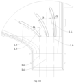
- an angle ⁇ between the straight line L5 formed by connecting the opposite ends of the guide surface 82 and the extension line of the inlet direction L6 of the air inlet 11 is 0°-70°.
- the opposite ends of the diversion component 80 in the airflow direction are respectively formed with a first end close to the air inlet 11 and a second end far away from the air inlet 11.
- the straight line L5 may also be understood as the straight line formed by connecting the first end of the diversion component 80 with its second end.
- the inlet direction L6 may be understood as the airflow direction at the position of the first end of the diversion component 80. In practical applications, there will be multiple airflows entering the airflow channel 10 through the air inlet 11. When multiple airflows flow towards the corresponding diversion component 80 along the airflow direction, each airflow will be cut and divided by the corresponding diversion component 80. At this time, the airflow direction corresponding to the first end of the diversion component 80 is defined as the inlet direction L5.
- the channel structure between the air inlet 11 and the diversion component 80 may be a straight channel, an arc-shaped channel, etc., but regardless of the channel structure between the diversion component 80 and the air inlet 11, the airflow direction ultimately in contact with the position of the first end of the corresponding diversion component 80 is the inlet direction L6.
- Arranging the guide surface 82 in the above-mentioned structural form between the air inlet 11 and the first-stage diversion region 23 can ensure that the guide surface 82 can guide the corresponding first diversion to the position corresponding to the first-stage diversion region 23, and the first diversion is not easily affected by the guide surface 82, avoiding the situation where the first diversion generates additional turbulence at the end of the guide surface 82 close to the first-stage diversion region 23.
- the end of the diversion component 80 close to the air inlet 11 may be arranged as a circular arc structure, and the two sides of the circular arc structure are respectively tangent to the guide surfaces 82 placed on opposite sides of the diversion component 80.
- the circular arc structure may divide the main airflow into two first stage diversions and guide them to the corresponding guide channels 81 on both sides, minimizing the turbulence caused by the main airflow when it impacts the end of the diversion component 80.
- the end of the diversion component 80 close to the air inlet 11 may also be designed as a conical structure.
- the first-stage diversion region 23 of this embodiment includes at least two separated and parallel diversion bodies 21.
- the diversion bodies 21 of the first-stage diversion region 23 are used to divide the airflow channel 10 into at least two diversion channels 22, thereby playing the roles of diffusion, turbulence, and acoustic guidance of the airflow as described above.
- the sound waves in the airflow undergo multiple and repeated contact frictions with the first-stage diversion region 23 and the muffling structure arranged in the first-stage diversion body 21, so that the sound waves are absorbed to a certain extent in the diversion channel 22 formed by the first-stage diversion region 23.
- resonance occurs between the airflow and the diversion body 21, thereby consuming and absorbing the sound waves of the first stage diversion.
- the diversion bodies 21 in the first-stage diversion region 23 are alternately arranged with the diversion component 80.
- This setting method may be understood as:
- an end of the diversion component 80 close to the first-stage diversion region 23 is directly facing the diversion channel 22 of the first-stage diversion region 23; as well as
- the diversion body 21 of the first-stage diversion region 23 is arranged facing the guide channel 81.
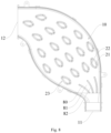
- this embodiment sets the number of diversion channels 22 in the first-stage diversion region 23 to n, where n ⁇ 3, and the corresponding number of guide channels 81 is (n-1). As shown in Fig. 9 , when the number of diversion channels 22 arranged in the first-stage diversion region 23 is 5, the corresponding guide channels 81 are 4.
- the number of diversion channels 22 in the first-stage diversion region 23 does not correspond to the number of guide channels 81.
- the corresponding guide channels 81 may also be set to 2, 3, etc.
- the branch airflow L2 may evenly enter the first-stage diversion region 23, so that the branch airflow L3 in each diversion channel 22 within the first-stage diversion region 23 is more uniform, facilitating further muffling and shock absorption processing in the second-stage diversion region 24, third-stage diversion region 25, etc.
- a sound-absorbing material 40 is installed inside the airflow channel 10.
- the sound-absorbing material 40 may be fitted around the periphery of each diversion body 21;
- the sound-absorbing material 40 may be arranged around the inner wall of the air duct housing 30;
- the sound-absorbing material 40 may be filled in the airflow channel 10, specifically, the sound-absorbing material 40 is filled in each diversion channel 22.
- the sound-absorbing material 40 is not provided in the guide channel 81, that is, the sound-absorbing material 40 is provided between the diversion component 80 and the air outlet 12.
- Fig. 13 is a simulation diagram of the airflow channel 10 of the muffling air duct device in this embodiment. It may be seen that under the action of the diversion component 80, the high-speed main airflow (the lighter colored part near the air inlet 11) may be evenly diverted and flow towards the first-stage diversion region 23. As the airflow passes through the first-stage diversion region 23, the second stage diversion region 24, the third-stage diversion region 25 in sequence, the airflow gradually becomes stable (the color gradually becomes uniform), so that the airflow may be smoothly discharged at the air outlet 12, achieving the effect of muffling and vibration reduction.
- the muffling air duct device further includes an air duct housing 30, which is hollow inside to form an airflow channel 10.
- the air inlet 11 and the air outlet 12 are both arranged in the air duct housing 30.
- Each diversion body 21 is arranged inside the air duct housing 30, so that each diversion channel 22 is formed inside the air duct housing 30.
- An avoidance space is opened on the surface of the air duct housing 30, which is opposite to the air inlet 11 and the air outlet 12.
- the air duct housing 30 may be equipped with an air guide pipe 31 extending from the air duct housing 30 at the air outlet, and an outlet airflow channel 311 is formed inside the air guide pipe 31 to restrict the flow direction of the gas discharged from the muffling air duct device.
- the air duct housing 30 may be equipped with an air duct connecting pipe 32 extending from the air duct housing 30 at the air inlet 11, and an air inlet channel 321 is formed inside the air duct connecting pipe 32 to restrict the flow direction of the gas entering the muffling air duct device and facilitate the connection between the muffling air duct device and the fan 50.
- the cross-sectional shapes of the inlet airflow channel 321 and the outlet airflow channel 311 may have various shapes, such as but not limited to: circular, square, trumpet shaped, and other irregular shapes.
- the diversion channel 22 is formed.
- a diversion channel 22 is formed between the side of the diversion body 21, namely the guide part, and the inner wall of the air duct housing 30.
- the air duct housing 30 includes an upper cover 33 and a lower cover 34 that cover each other.
- the airflow channel 10 may be formed by the assembly of the upper and lower housings, and the diversion body 21 may be arranged on the upper or lower housings, which can improve the processing efficiency through integrated molding during the processing.
- the upper and lower housings described in this embodiment are specifically the two housings of the muffling air duct device that are relatively close to and far away from the cleaning robot when installed in the cleaning robot.
- the housing that is relatively close to the cleaning robot is defined as the lower housing, and the housing that is relatively far away from the cleaning robot side is defined as the upper housing.
- the upper cover 33 and the lower cover 34 may be detachably connected by buckles or fixedly connected by threaded connections.
- the materials of the air guide part 212, upper cover 33, and lower cover 34 mentioned above include but are not limited to a combination of one or more of resin materials, plastic materials, and metal materials.
- an end of the diversion body 21 is arranged on the lower cover 34. After the upper cover 33 and the lower cover 34 are closed, the other end of the diversion body 21 may be pressed against the upper cover 33, so that the diversion body 21 is horizontally placed between the upper cover 33 and the lower cover 34.
- the sound-absorbing material 40 is installed inside the airflow channel 10.
- the diversion body 21 includes a diversion main body integrally formed on the air duct housing 30 and the sound-absorbing material 40 fitted around the periphery of the diversion main body.
- the diversion main body integrally formed on the air duct housing 30 does not need to have assembly structures or reserved installation positions between the air duct housing 30 and the diversion main body, which is more conducive to the production and processing of the device.
- the sound-absorbing material 40 is arranged around the inner wall of the air duct housing 30.
- the sound-absorbing material 40 is different from the material of the diversion body.
- the diversion body 21 may divert the airflow while allowing the air to come into contact with the sound-absorbing material 40 as much as possible. After the airflow is diverted into at least two channels by the diversion body 21, each airflow may come into contact with the sound-absorbing material 40.
- the diversion treatment can reduce the airflow velocity, increase the contact area between the air and the sound-absorbing material 40, and improve the sound-absorbing effect of the sound-absorbing duct device.
- the upper and lower sides of the upper and lower shells used to enclose the airflow channel 10 may further be equipped with sound-absorbing materials 40, but there should be a certain gap between the sound-absorbing materials 40 located on the upper and lower housings to ensure that gas can smoothly pass through the diversion channel 22.
- the sound-absorbing material 40 may be in the form of a sheet or block structure.
- the sound-absorbing material 40 may be attached or clamped to the inner wall of the air duct housing 30 or the periphery of each diversion body 21.
- the sound-absorbing material 40 may be arranged by filling the ventilation space.
- the sound-absorbing material 40 is a sheet-like structure, which is attached to the outer peripheral wall of each diversion body 21 and the inner wall of the air duct housing 30.
- the specific function of the sound-absorbing material 40 is to reduce the noise generated by the exhaust of the fan 50 during the operation of the cleaning robot.
- some necessary conditions should be met.
- the sound-absorbing material 40 needs to be a breathable component, or may be said that the air resistance of sound-absorbing material 40 should not be too high, so that sound-absorbing material 40 can reduce noise in the airflow without affecting the normal operation of the fan 50.
- the sound-absorbing material 40 needs to be a component with good muffling effect, so as to minimize noise and enhance the user experience.
- the sound-absorbing material 40 is sound-absorbing cotton, and the material of sound-absorbing cotton is not limited to fiber cotton, polyurethane sound-absorbing cotton, sponge, pearl cotton, etc. Its thickness is not limited. It may be understood that the internal structure of the sound-absorbing cotton is mesh shaped. When noise enters the surface of the sound-absorbing cotton, a part of the noise will be reflected by the sound-absorbing cotton, and the reflected noise will cancel out the subsequent noise transmitted to the direction of the sound-absorbing cotton, achieving an once-sound-absorbing effect. Part of the noise will pass through the sound-absorbing cotton and be absorbed by the sound-absorbing cotton, and another part of the noise will be lost when it rubs against the surrounding medium due to its own vibration propagation, ultimately achieving the sound-absorbing effect.
- the sound-absorbing cotton is a material made of single or multiple different fibers processed through various processes, among which polyester sound-absorbing cotton has a better sound-absorbing effect.
- Polyester sound-absorbing cotton is composed of 100% polyester fibers that have undergone high-tech hot pressing and are formed in the shape of cocoon cotton, which has good air permeability.
- the sound absorption coefficient of polyester sound-absorbing cotton reaches 0.94 in the noise range of 125-4000HZ, which can maximize the absorption of the noise generated by the exhausts of the fan 50.
- the noise frequency band will not continuously decay with distance and time as the airflow passes through each diversion channel 22. Therefore, as the noise flows through each diversion channel 22 in the airflow direction, its frequency band will also decrease.
- the preset energy absorption frequency band of the sound-absorbing material 40 close to the air inlet 11 is higher than that of the sound-absorbing material 40 close to the air outlet 12, so that the sound-absorbing frequency band of the sound-absorbing duct device covers a wider range of frequency bands and improves the applicability of the sound-absorbing duct device.
- the muffling duct device in this embodiment does not have a completely silent effect on the fan 50 and the airflow discharged by the fan 50. It only reduces the noise, allowing users to almost ignore the reduced noise when applying the muffling duct device to the corresponding cleaning equipment.
Landscapes
- Engineering & Computer Science (AREA)
- Mechanical Engineering (AREA)
- Duct Arrangements (AREA)
- Electric Vacuum Cleaner (AREA)
- Soundproofing, Sound Blocking, And Sound Damping (AREA)
Abstract
Description
- The present disclosure claims the priority of a
Chinese patent application with the Application No. 202220576584.7 and the title of "MUFFLING AIR DUCT DEVICE, AIR DUCT COMPONENT, AND CLEANING ROBOT", which is filed to CNIPA on March 15, 2022 - The present disclosure relates to the field of air purification, and in particular to a muffling air duct device, an air duct component, and a cleaning robot.
- The existing cleaning equipment, such as vacuum cleaners, intelligent cleaning robots, etc., all have functions such as vacuuming and dust removal. The working principle of their vacuuming function is to use an electric motor to drive blades for rotation at high speed, thereby generating negative air pressure inside the sealed housing and sucking up dust from the ground or the required cleaning position.
- However, due to the continuous high-speed rotation of the electric motor during operation, the high-speed airflow generated by the motor will rub against other air and equipment components, resulting in significant noise in the air duct system of the cleaning equipment during suction and dust removal. The noise not only affects the user experience of using the corresponding cleaning equipment products, but also the vibration generated by the friction between the air also affects the stability of the cleaning equipment during use, which to some extent affects the cleaning effect of the equipment.
- The purpose of the present disclosure is to provide a muffling air duct device, an air duct component, and a cleaning robot that solves a technical problem of excessive noise in a working state of cleaning equipment while ensuring the efficiency of the cleaning equipment.
- In order to solve the above technical problem, the present disclosure adopts the following technical solutions.
- According to a first aspect, a muffling air duct device is provided, which includes:
- an airflow channel equipped with an air inlet and an air outlet connected to external environment at both ends, where the air inlet and the air outlet is configured to restrict an inlet direction and an outlet direction of the airflow channel respectively; and
- multi-stage diversion components located between the air inlet and the air outlet in the airflow channel, where each stage of diversion components separate the airflow channel into several diversion channels, and the diversion channels formed by the separation of each stage of diversion components are communicated with each other;
- the diversion component including at least one diversion body, and each of the diversion bodies separating the airflow channel into at least two diversion channels.
- According to a second aspect, an air duct component is provided, which includes:
- a muffling air duct device mentioned in the first aspect;
- a fan having an exhaust duct, where the exhaust duct is connected to the airflow channel through the air inlet.
- According to a third aspect, a cleaning robot is provided, which includes:
- an air duct component mentioned in the second aspect; and
- a vacuum cleaner, where the vacuum cleaner has a side connected to external environment of the cleaning robot, and the fan further has a suction duct connected to the exhaust duct, another side of the vacuum cleaner is connected to the suction duct.
- The beneficial effects of the present disclosure are: in the muffling air duct device, the inlet direction and the outlet direction of the airflow channel are at least partially offset from each other, thereby extending the length of the airflow path in the airflow channel. During the process of airflow flowing towards the outlet, collisions occur in the airflow channel, causing energy loss and reducing airflow velocity, achieving preliminary muffling effect;
multi-stage diversion components, being installed in the airflow channel, each stage of diversion components dividing the airflow channel into several diversion channels, further extending a path length inside the airflow channel, the diversion body performing diverting processing on the airflow to allow multiple secondary airflows separated from the main airflow to enter each diversion channel separately. In addition, each stage of diversion component can further divert the airflow, indirectly increasing a contact area between the air and each diversion bodies and the length of the airflow path. This allows sound waves to be more fully absorbed and muffled in the airflow channel, and can also avoid the situation where the airflow is discharged through the shortest path in the airflow channel. Without increasing the size of the equipment and air duct, it is ensured that the air resistance parameters in the airflow channel meet working requirements of the cleaning equipment, while improving the muffling effect. - Hereinafter, the present disclosure will be further explained in details based on the accompanying drawings and embodiments.
-
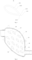
Fig. 1 is one schematic diagram of a structure of a muffling air duct device according to an embodiment of the present disclosure. -
Fig. 2 is another schematic diagram of the structure of the muffling air duct device according to an embodiment of the present disclosure. -
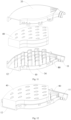
Fig. 3 is one explosion view of the muffling air duct device according to an embodiment of the present disclosure. -
Fig. 4 is one schematic diagram of an internal structure of the muffling air duct device according to an embodiment of the present disclosure (omitting a upper cover and a sound-absorbing material). -
Fig. 5 is a schematic diagram of a structure of a diversion body according to an embodiment of the present disclosure. -
Fig. 6 is a schematic diagram of the division of the airflow channel diversion region according to an embodiment of the present disclosure. -
Fig. 7 is a schematic diagram of an airflow direction in an airflow channel according to an embodiment of the present disclosure. -
Fig. 8 is another schematic diagram of an internal structure of the muffling air duct device according to an embodiment of the present disclosure. -
Fig. 9 is a schematic diagram of an airflow direction inside the muffling duct device according to an embodiment of the present disclosure. -
Fig. 10 is a schematic diagram of a relationship between the fluid structure and the inlet direction according to an embodiment of the present disclosure. -
Fig. 11 is another exploded view of the muffling air duct device according to an embodiment of the present disclosure. -
Fig. 12 is a schematic diagram of an installation manner of a sound-absorbing material according to an embodiment of the present disclosure. -
Fig. 13 is a simulation diagram of an airflow channel according to an embodiment of the present disclosure. -
Fig. 14 is an assembly view of the air duct component according to an embodiment of the present disclosure. -
Fig. 15 is another assembly view of the air duct component according to an embodiment of the present disclosure. -
Fig. 16 is a simplified schematic diagram of a cleaning robot according to an embodiment of the present disclosure. - In the
figure: 10 . Airflow channel; 11. Air inlet; 12. Air outlet; 13. First channel; 14. Second channel; 20. Diversion component; 21. Diversion body; 211, Air ward part; 2111. First diversion surface; 2112. Second diversion surface; 212. Air guide part; 2121. Air guide surface; 22. Diversion channel; 23. First-stage diversion region; 24. Second-stage diversion region; 25. Third-stage diversion region; 26. Fourth-stage diversion region; 27. Five-stage diversion region; 28. Six-stage diversion region; 30. Air duct housing; 31. Air pipe; 311. Outlet airflow channel; 32. Air duct connecting pipe; 321. Inlet airflow channel; 33. Upper cover; 34. Lower cover; 40. Sound-absorbing material; 50. Fan; 51. Draft duct; 52. Exhaust duct; 53. Shock-absorbing hose; 60. Base body; 70. Dust collection box; 80. Diversion component; 81. Guide channel; 82. Guide surface. - In order to make the technical problem to be solved, the technical solution to be adopted, and the technical effect to be achieved by the present disclosure clearer, the technical solution of the embodiments of the present disclosure will be further described in detail with reference to the accompanying drawings. Obviously, the described embodiments are only a part of the embodiments of the present disclosure, not all thereof. Based on the embodiments in the present disclosure, all other embodiments obtained by those skilled in the art without creative labor are within the scope of protection of the present disclosure.
- In the description of the present disclosure, unless otherwise specified and limited, the terms "connected" and "fixed" should be broadly understood, for example, it may be fixed connections, detachable connections, or integrated; or it may be a mechanical connection or an electrical connection; or it may be directly connected or indirectly connected through an intermediate medium; or it may be a connection within two components or an interaction relationship between two components. For those skilled in the art, the specific meanings of the above terms in the present disclosure may be understood in specific situations.
- In the present disclosure, unless otherwise specified and limited, a first feature "above" or "below" a second feature may include direct contact between the first and second features, or may include contact between the first and second features through another feature between them instead of direct contact. Moreover, the first feature being "above", "over", and "on" the second feature includes the first feature being directly above and diagonally above the second feature, or simply indicating that the first feature is horizontally higher than the second feature. The first feature being "below", "underneath", and "under" includes the first feature being directly below and diagonally below the second feature, or simply indicating that the first feature is horizontally lower than the second feature.
- As shown in
Figs. 1-2 , the embodiment of the present disclosure provides a muffling air duct device, the muffling air duct device is mainly used in cleaning equipment. The muffling air duct device reduces the exhaust noise of cleaning equipment, such as cleaning robots, by addingmulti-stage diversion components 20 in anairflow channel 10. This muffling air duct device is suitable for the characteristics of small installation space and high space utilization required inside cleaning robots. - As shown in
Fig. 16 , this embodiment provides a cleaning robot, and the cleaning robot is an intelligent household appliance, also known as an automatic cleaning machine, intelligent vacuum robot, vacuum cleaner, etc. It is a type of intelligent household appliance that may automatically complete cleaning work in its region with certain artificial intelligence. Cleaning robots generally use brushing and vacuum manners to first absorb floor dust into their owndust collection box 70, thereby completing the function of floor cleaning. The cleaning robot is operated remotely using a remote control or through the control panel on the body, which is mainly disc-shaped. Using rechargeable batteries for operation, it is generally possible to set a time to schedule cleaning and self-charge. There are sensors installed in front that may detect obstacles. If encountering walls or other obstacles, they will turn on their own and follow different routes according to different program settings of the system to systematically clean the area. The cleaning robot generates noise during the operation of the fan, which affects the usage of the user and also has a certain impact on the physical health of the user. - Referring to
Fig. 16 , it is a schematic diagram of a partial structure of a cleaning robot applied to the muffling air duct device in this embodiment. The cleaning robot generally has an outer shell (not shown in the figure) and a base component arranged inside the outer shell. The base component includes abase body 60, and by setting driving wheels, batteries, air duct components and other components on thebase body 60, the cleaning robot described in this embodiment is assembled. The outer shell may play a role in protecting the components in the base assembly of the cleaning robot. A corresponding avoidance space may be opened at anair outlet 12 of the muffling air duct device on the outer shell, providing air blown out from theair outlet 12 to be discharged outside the outer shell. - The above-mentioned
dust collection box 70 is used for temporary storage of dust and garbage collected by the cleaning robot. Thedust collection box 70 may be installed on the outer shell of the cleaning robot through a detachable installation manner, or fixed relative to the outer shell. By arranging a dust outlet, users may clean the collected materials inside in a manner of automatic dust exhaust through the workstation or a manner of manual dust exhaust. Thedust collection box 70 may be equipped with a dust inlet and an exhaust outlet. The dust inlet may be connected to a dust suction channel (not shown) on the bottom body of the cleaning robot. A dust suction part is formed on the dust suction channel that is connected to the outside of the cleaning robot. When the cleaning robot is in use, the dust suction part is facing the floor to be cleaned by the cleaning robot. The other side of the dust suction part is connected to theinlet airflow channel 321 of the muffling air duct device through the dust suction channel, thedust collection box 70, and anexhaust duct 52 of afan 50. The exhaust outlet of thedust collection box 70 is used to connect with thedraft duct 51 of thefan 50. Thefan 50 is a main power output component of the air duct assembly in the cleaning robot. Thefan 50 is used to provide power and create negative pressure in the dust suction channel, thereby sucking dust from the ground into thedust collection box 70. - As shown in
Figs. 14-15 , this embodiment is applied to the air duct component of the cleaning robot. Thefan 50 according to this embodiment is a component that converts input electrical energy into mechanical energy, thereby increasing gas pressure and delivering gas. Thefan 50 according to this embodiment has adraft duct 51 and anexhaust duct 52. Thedraft duct 51 may be arranged at the top or bottom of thefan 50, and theexhaust duct 52 may be arranged at the side of thefan 50. This can effectively utilize the internal space of the cleaning robot, and thefan 50 can also have better air force effect. - A shock-absorbing
hose 53 is arragned between theexhaust duct 52 and the muffling air duct device. The shock-absorbinghose 53 is made of a material with shock-absorbing function, which may be made of soft materials such as soft rubber. The shock-absorbinghose 53 can reduce the noise at theexhaust duct 52 of thefan 50 through shock-absorbing, and also improve the airtightness between thefan 50 and the muffling air duct device, ensuring the stability of air flow and thereby improving the reliability of the air duct component. - The
fan 50 includes a housing and an air supply component arranged inside the housing. A space for air flow is formed between the housing and the air supply component, and the space is connected to the external environment of the housing through thedraft duct 51 and theexhaust duct 52, respectively. The housing can protect the air supply components and prevent airflow leakage. Theexhaust duct 52 is tangent to the rotation direction of the air supply components, making the airflow inside thefan 50 smoother and increasing the air supply efficiency of thefan 50. - As shown in
Figs. 3-5 , the muffling air duct device of this embodiment includes anairflow channel 10, and theairflow channel 10 provides a gas discharge channel space for the cleaning equipment during the dust suction process, thereby restricting the direction of gas flow discharged by thefan 50. The two ends of theairflow channel 10 are respectively equipped with anair inlet 11 and anair outlet 12 that are connected to the external environment. According to the above scheme, in the application of the cleaning robot, theair inlet 11 is used to communicate with theexhaust duct 52 of thefan 50, and the gas discharged from theexhaust duct 52 may be discharged from theair outlet 12 through theairflow channel 10 to the outside of the cleaning robot. Theair inlet 11 and theair outlet 12 are respectively used to restrict the inlet and outlet directions of theairflow channel 10. The inlet and outlet directions are at least partially offset from each other, and the offset between the inlet and outlet directions may be understood as the fact that the inlet and outlet directions are at least partially facing in different directions. It may also be understood that even if they are in the same direction, the inlet and outlet directions may be offset on the same horizontal plane or on different horizontal planes. The inlet and outlet directions are also at least partially offset in two positions, so that at least some of the airflow path in theairflow channel 10 may have disturbance structure such as bent, curved, or other ways that may disrupt the flow airflow direction. When the airflow passes through theairflow channel 10, it will collide with a side wall of theairflow channel 10, changing the flow direction and inevitably causing energy loss, forming a simple maze duct structure that reduces the airflow velocity and achieves preliminary muffling. - In the
airflow channel 10, from the end close to theair inlet 11 to the end close to theair outlet 12, that is, in the airflow direction from theair inlet 11 to theair outlet 12 of theairflow channel 10,multi-stage diversion components 20 are sequentially set up. Each stage ofdiversion components 20 divides theairflow channel 10 intoseveral diversion channels 22. The main airflow entering theairflow channel 10 from theair inlet 11 may be diverted by thediversion channels 22, thus forming a secondary airflow. After respectively entering thecorresponding diversion channels 22, the secondary airflow is guided by thediversion channels 22, changing the flow direction and extending the airflow path of the secondary airflow. Each secondary airflow will experience energy loss during the process of changing the flow direction, reducing the flow velocity of each secondary airflow. Corresponding muffling may be arranged in thediversion channels 22. The structure is such that the sound waves of the secondary airflow are buffered and absorbed within thediversion channel 22, Thediversion channels 22 formed by each stage of diversion are communicated, allowing each secondary airflow to re-merge near theair outlet 12 and be discharged from the muffling duct device. - In this embodiment, the structure and muffling design of the
diversion channel 22 need to ensure that the air resistance parameters meet the requirements of the cleaning robot during operation, and that the flow of each secondary airflow in thediversion channel 22 is smooth, so that the negative pressure formed at thedraft duct 51 of thefan 50 in the application of the cleaning equipment is sufficient to suck in dust at the suction part. - Specifically, the
diversion component 20 includes at least onediversion body 21, eachdiversion body 21 separating theairflow channel 10 into at least twodiversion channels 22, thereby playing a role in diffusing, disturbing, and guiding the airflow with sound waves. When the secondary airflow enters thecorresponding diversion channel 22, its sound waves undergo multiple and repeated contact friction with the muffling structure arranged in thediversion channel 22, allowing the sound waves to be absorbed in thediversion channel 22 or resonate with thediversion body 21 when contact friction occurs with thediversion body 21, thereby consuming and absorbing the sound waves of the secondary airflow. - In an embodiment, in any two
adjacent diversion components 20, the later stage ofdiversion body 21 is arranged at one of thediversion channels 22 separated by the former stage ofdiversion body 21. It may be understood that the main airflow entering theairflow channel 10 from theair inlet 11 is diverted by thediversion body 21 in the first stage ofdiversion component 20 closest to theair inlet 11 to form at least two secondary airflows. The secondary airflows flow in thediversion channels 22 separated by the first stage ofdiversion component 20 and undergo muffling treatment. Each secondary airflow will be guided by thecorresponding diversion channel 22 to the later stage ofdiversion component 20. Subsequently, at least one secondary airflow will be further diverted, disturbed at the second stage ofdiversion body 21, and further diverted secondary airflow flows into thesubsequent diversion channel 22 for further muffling treatment. Thus, multiple levels of branches ofdiversion channels 22 are formed within theairflow channel 10. The sound waves in the airflow are continuously diverted and disturbed before being subjected to muffling treatment, and then diverted and disturbed again, fully increasing the contact area between each airflow and thediversion body 21 and the muffling structure. The sound waves are buffered by eachdiversion channel 22, allowing the majority of their energy to be consumed within thediversion channel 22, thereby effectively improving the muffling effect of the muffling air duct device on the sound waves in the airflow. - In this embodiment, at least one side wall of the
diversion channel 22 is formed through the side of thediversion body 21, and the other side wall of thediversion channel 22 may be determined based on the structure located on the side of thediversion body 21. - In one case, if the number of
diversion bodies 21 in the same stage of thediversion component 20 is greater than or equal to two, any twoadjacent diversion bodies 21 in the same stage of thediversion component 20 are arranged opposite to each other. On the opposite side of the twodiversion bodies 21, twodiversion channels 22 are formed from the perspective of airflow, and these twodiversion channels 22 will eventually merge. The side walls of these twodiversion channels 22 are respectively formed by twoadjacent diversion bodies 21. - In another case, the number of
diversion bodies 21 in the same stage of thediversion component 20 is one, and adiversion channel 22 is formed between the side of thediversion body 21 and the inner wall of the muffling duct device; or when the number ofdiversion bodies 21 in the samelevel diversion component 20 is greater than or equal to two, adiversion channel 22 is formed between the side of thediversion body 21 closest to the inner wall of the muffling duct device and the inner wall of the muffling duct device. - According to the above situation, each secondary airflow may be guided to flow between the inner wall of the muffling duct device and the
diversion body 21, as well as in thediversion channel 22 formed between eachdiversion body 21. - In another embodiment, a partition may be arranged between any two
adjacent diversion bodies 21 of the same stage ofdiversion component 20, and a partition may be arranged between thediversion bodies 21 and the inner wall of the muffling air duct device, forming adiversion channel 22 through the partition and the side of thediversion bodies 21. - As shown in
Fig. 6 , taking the schematic diagram of the internal structure of theairflow channel 10 as an example, in this embodiment, the first stage ofdiversion component 20 closest to theair inlet 11 includes adiversion body 21, and the second stage ofdiversion component 20 after the first stage ofdiversion component 20 includes twodiversion bodies 21. Thediversion bodies 21 in the second stage ofdiversion component 20 are respectively arranged on the paths of twodiversion channels 22 formed by thediversion body 21 of the first stage ofdiversion component 20. In this way, the main airflow entering from theair inlet 11 will be separated by thediversion body 21 located in the first stage ofdiversion component 20 to form two secondary airflows. The two secondary airflows will flow along thediversion channels 22 formed on both sides of the first stage ofdiversion body 21, respectively, towards the twodiversion bodies 21 located in the second stage ofdiversion component 20. Subsequently, when the secondary airflows respectively come into contact with the second stage ofdiversion body 21, they will be separated into two secondary airflows, ultimately forming at least four secondary airflows. When the airflows are not separated once, their flow direction, velocity, and flow rate will change, thereby improving the contact area between eachdiversion channel 22 and its internal gas, effectively enhancing the sound wave muffling effect. - It should be noted that the first stage of
diversion component 20, which is thediversion component 20 in the first stage of diversion region in this embodiment, is thediversion component 20 arranged closest to theair inlet 11, the last stage ofdiversion component 20, which is thediversion component 20 in the sixth stage of diversion region in this embodiment, is thediversion component 20 arranged closest to theair outlet 12, the second stage ofdiversion component 20, the third stage ofdiversion component 20, and the subsequent stage ofdiversion components 20 are thediversion components 20 arranged in sequence along the airflow direction of theairflow channel 10 in each stage of diversion region. The formerstage diversion component 20 refers to thediversion component 20 that is relatively located in the diversion region close to theair inlet 11, while the second stage ofdiversion component 20 refers to thediversion component 20 that is relatively located in the diversion region close to theair outlet 12. - Here, the principle of noise generated by the
exhaust duct 52 offan 50 will be described. Due to the small diameter ofexhaust duct 52, the air supply component generates a large air pressure inside the housing of thefan 50 during rotation. Therefore, when high-pressure air is discharged fromexhaust duct 52, it will cause impact vibration on the external air, resulting in noise. Therefore, the faster the speed of the air supply component and the higher the air pressure insideexhaust duct 52, the greater the noise generated by thefan 50 during the exhaust process. In order to fully reduce the airflow noise discharged from theexhaust duct 52 and improve the muffling effect of sound waves, the size of theairflow channel 10 needs to be larger than that of theexhaust duct 52, providing sufficient buffer space for the discharged airflow, so that the noise can be buffered and absorbed in the muffling duct device. - In order to further improve the muffling effect on sound waves within the limited installation space of the muffling duct device adapted to the cleaning robot, the
diversion body 21 includes anair ward part 211 and anair guide part 212. It should be noted that theair ward part 211 and theair guide part 212 may be integrated into a single molding structure to reduce the processing and installation difficulties of thediversion body 21. Theair ward part 211 and theair guide part 212 may also be two independent components that are coupled to each other in the air path structure formed by them, and are arranged in theairflow channel 10 through independent processing, installation, and other manners. - In the
same diversion body 21, theair ward part 211 is arranged at an end of thediversion body 21 close to theair inlet 11, used to separate theairflow channel 10 into at least two alternatingdiversion channels 22. When the airflow flows towards thediversion body 21, theair ward part 211 is a part where thediversion body 21 first comes into contact with the airflow. Theair ward part 211 will block the airflow, change the airflow direction, and divide the airflow into at least two channels, each of divided airflow will flow into thecorresponding diversion channel 22. There are at least twoair guide parts 212, each ofair guide parts 212 is arranged on opposite sides of thediversion body 21. Each ofair guide parts 212 forms one side wall of itscorresponding diversion channel 22, and theair guide part 212 is used to guide the airflow direction in itscorresponding diversion channel 22. The airflow path formed by the separation of eachair guide part 212 and theair ward part 211 is consistent, so that all the airflow diverted by theair ward part 211 can be guided by theair guide part 212, and the buffering and absorption effect of noise and sound waves in the airflow can also be improved. - Specifically, in the
same diversion body 21, the distance between any two adjacentair guide parts 212 is greater than or equal to that of theair ward parts 211, thereby forming a diffusive structure ofdiversion channels 22, providing sufficient installation space for the later stage ofdiversion body 21 and sufficient flow space for the air in the first stage. - This embodiment takes the example of being able to separate two airflows from each
diversion body 21. Theair ward part 211 includes afirst diversion surface 2111 and asecond diversion surface 2112 arranged at an angle. Thefirst diversion surface 2111 and thesecond diversion surface 2112 are used to separate theairflow channel 10 to form adiversion channel 22. An end of thefirst diversion surface 2111 is connected with that of thesecond diversion surface 2112, and thefirst diversion surface 2111 and thesecond diversion surface 2112 may gradually extend in the direction away from each other and towards theair outlet 12. It may be understood that, as shown inFig. 7 , when a main airflow L1 comes into contact with theair ward part 211, the airflow will be separated into two secondary airflows by the end of the first air ward surface in contact with the second air ward surface. The two separated branch airflows L2 flow in the directions guided by the first andsecond diversion surfaces air guide part 212. - Continuing from the above, in the case where two branch airflows L2 may be separated by the
air ward part 211, there are twoair guide parts 212, each ofair guide parts 212 includes anair guide surface 2121. An end of theair guide surface 2121 is connected to thefirst diversion surface 2111 or thesecond diversion surface 2112, and the other end of theair guide surface 2121 extends along the airflow direction of thecorresponding diversion channel 22. It may be understood that in thesame diversion body 21, taking theair guide part 212 being two as an example, theair guide surface 2121 includes a first guide surface and a second guide surface. An end of the first guide surface is connected to thefirst diversion surface 2111, and an end of the second guide surface is connected to thesecond diversion surface 2112. The other ends of the first guide surface and the second guide surface are facing away from each other and extend towards the direction of theair outlet 12. It should be noted that the airflow path formed by thefirst diversion surface 2111 is coupled with the airflow path of the first guide surface, and the airflow path formed by thesecond diversion surface 2112 is coupled with the airflow path of the second guide surface. - The space between each
air guide surface 2121 gradually increases from the end close to theair ward part 211 to the end far away from theair ward part 211. In the case where there are twoair guide parts 212, as the two air guide surfaces 2121 extend in the direction away from each other, the space between them gradually increases to form a diffusive structure, providing sufficient installation space for the later stage ofdiversion body 21 and sufficient airflow space for the later stage ofdiversion channel 22. - It may be understood that the peripheral shape of the
diversion body 21 includes but is not limited to a combination of one or more of droplet shape, circle, diamond shape, and rectangle. - The above description of the structure of the
diversion body 21 is applicable to cases where the periphery of thediversion body 21 has irregular shapes such as water droplets, diamonds, rectangles, etc. In this embodiment, the shape of the periphery of thediversion body 21 adopts a water droplet structure. - The
air ward part 211 may also be a plane, as long as it may achieve the effect of diverting airflow. - There are connected
first channel 13 andsecond channel 14 formed in theairflow channel 10. Theair inlet 11 is correspondingly connected to thefirst channel 13, and theair outlet 12 is correspondingly connected to thesecond channel 14. The number ofdiversion components 20 is greater than 2. The number ofdiversion bodies 21 of each stage ofdiversion components 20 in thefirst channel 13 increases stage by stage in the airflow direction, and the number ofdiversion bodies 21 of each stage ofdiversion components 20 in thesecond channel 14 decreases stage by stage in the airflow direction. Thus, the main airflow is separated into multiple secondary airflows after entering theairflow channel 10, and the multiple secondary airflows may merge into one airflow and be discharged from theair outlet 12 when approaching theair outlet 12. Through the internal structure of the air duct, the muffling requirements of the air duct device are met, and the volume of the air duct device gradually increases from theair inlet 11 to theair outlet 12 and then gradually decreases, minimizing the overall volume of the air duct device and meeting the installation needs of the cleaning robot. - As shown in
Figs. 6-7 , theairflow channel 10 is sequentially equipped with multi-stage diversion regions along the airflow direction, and each of the diversion regions is equipped with thediversion component 20; the number ofdiversion channels 22 separated by any two adjacent diversion regions gradually increases or decreases in the airflow direction. For example, theairflow channel 10 is sequentially provided with six diversion regions in the airflow direction, with the first stage of diversion region closest to theair inlet 11, namely the first-stage diversion region 23, including adiversion body 21. Theair ward part 211 of thediversion body 21 located in the first-stage diversion region 23 is arranged towards theair inlet 11. The main airflow L1 entering from theair inlet 11 is separated into two branch airflows L2 under the diversion of the first-stage diversion region 23, and the two secondary airflows flow along the separateddiversion channels 22. Thediversion component 20 in the subsequent second-stage diversion region 24 includes twodiversion bodies 21. The twodiversion bodies 21 located in the second-stage diversion region 24 are respectively arranged on the path of the twodiversion channels 22 separated by the first-stage diversion region 23. Theair ward part 211 of thediversion body 21 in the second-stage diversion region 24 faces the air ward direction of therespective diversion channels 22, and diverts the two branch airflows L2 into four branch airflows L3-1. The branch airflows L3-1 between twoadjacent diversion bodies 21 merge to form a merging L3-2 after flowing along thediversion channels 22 for a certain distance. Thediversion component 20 of the third-stage diversion region 25 includes threediversion bodies 21, and the threediversion bodies 21 are respectively arranged on thediversion channels 22 formed by the separation of the second-stage regions. Onediversion body 21 located in the third-stage diversion region 25 is arranged on the merging channel to divert the merging L3-2, while thediversion bodies 21 located on both sides divert the branch airflow L3-1 on both sides of the second-stage diversion region 24, forming six secondary airflows L4-1. The secondary airflows L4-1 between twoadjacent diversion bodies 21 merge to form the merging L4-2 after flowing for a certain distance. The diversion section of the fourth-stage diversion region 26 includes fourdiversion bodies 21, which follow the same diversion principle as the third-stage diversion region 25. The fourdiversion bodies 21 correspond to the secondary airflow L4-1 and the two merging L4-2 on both sides of the third-stage diversion body 21 for diversion. Thediversion body 21 in the fifth-stage diversion region 27 and the sixth-stage diversion region 28 gradually decreases, ultimately allowing each secondary airflow and merging to converge and be discharged from theair outlet 12. During this process, the main airflow may be separated into multiple secondary airflows with relatively lower flow rates than the main airflow, in order to gradually perturb, buffer, and absorb each secondary airflow. Finally, the airflow with absorbed noise and sound waves can be re merged and discharged from theair outlet 12. - As shown in
Figs. 8-9 , the muffling air duct device further includes adiversion component 80, and thediversion component 80 may be arranged between theair inlet 11 and thediversion component 20. For example, thediversion component 80 may be arranged between theair inlet 11 and the first-stage diversion region 23, so that the airflow flowing into theairflow channel 10 through theair inlet 11 may all pass through thediversion component 80. It should be noted that thediversion component 80 is used to separate theairflow channel 10 intomultiple guide channels 81, similar to the arrangement of thediversion body 21 in theairflow channel 10. Eachguide channel 81 is arranged side by side in theairflow channel 10, andmultiple diversion bodies 21 are arranged in the first-stage diversion region 23 to formmultiple diversion channels 22. At that time, thediversion channel 22 of the first-stage diversion region 23 and theguide channel 81 are alternately arranged and connected to each other. For example, as shown inFig. 9 , the main airflow L1 flowing into theairflow channel 10 through theair inlet 11 may be divided into multiple corresponding branch airflow L2 flowing into eachguide channel 81 under the action of thediversion component 80. The branch airflow L2 flows in the direction of the first-stage diversion region 23 under the guidance of thediversion component 80 and ultimately acts on the first-stage diversion region 23. Under the action of the first-stage diversion region 23, each branch airflow L2 flows into thecorresponding diversion channel 22 formed by the first-stage diversion region 23, ultimately implementing the above-mentioned muffling and vibration reduction of the airflow. - By implementing the above scheme, the main airflow L1 may relatively uniformly flow into each
guide channel 81 under the action of thediversion component 80 to form a branch airflow L2, and uniformly diffuse into eachdiversion channel 22 formed by the first-stage diversion region 23 under the guidance of eachguide channel 81 to form a branch airflow L3. In this way, the branch airflow L3 flowing into eachdiversion channel 22 of the first-stage diversion region 23 is relatively uniform, improving the efficiency of the interaction between the airflow in theairflow channel 10 and the first-stage diversion region 23. To a certain extent, it ensures that eachdiversion body 21 in the first-stage diversion region 23 may have the same noise and vibration reduction effect on the second stage diversion, avoiding the situation where the airflow is discharged through the shortest path in theairflow channel 10. - It should be noted that the main function of the
diversion component 80 is to separate the main airflow into multiple branch airflows L2, and evenly spread the branch airflows L2 to the first-stage diversion region 23. Therefore, thediversion component 80 should ensure the relative smoothness of the first stage diversion in theguide channel 81, avoiding excessive deceleration or disturbance of the airflow in theguide channel 81, which may affect the effect of the subsequent branch airflows L2 being disturbed by the first-stage diversion region 23. - In an embodiment, the
guide channel 81 may be formed between any twoadjacent diversion components 80, or may be formed by thediversion component 80 cooperating with the channel side wall of theairflow channel 10. - Referring to
Figs. 8-9 , thediversion component 80 is formed with aguide surface 82 that guides the airflow from theair inlet 11 to the first-stage diversion region 23. Theguide surface 82 extends from an end close to theair inlet 11 towards the first-stage diversion region 23, so that the main airflow L1 enters theguide channel 81 and forms a branch airflow L2, and is guided to the corresponding position of the first-stage diversion region 23 according to the extension direction of theguide surface 82. - As an example, the
diversion component 80 may be one of other irregular structures such as a plate-like structure, a block structure, etc., and at least twoguide surfaces 82 may be provided on thediversion component 80. Taking the diversion body as a plate-like structure with twoguide surfaces 82 as an example, the twoguide surfaces 82 are respectively formed on the opposite side surfaces of the diversion body. Theguide channel 81 may be formed between anyguide surface 82 and the channel side wall of theairflow channel 10, or between any two adjacent and opposite guide surfaces 82 when multiple diversion bodies are arranged. - In order to reduce the influence of the
guide surface 82 on the airflow velocity and other airflow parameters, and ensure that the first stage diversion can be quickly diverted into the first stage diversion by thediversion component 80 and then flow into the first-stage diversion region 23, theguide surface 82 may be arranged as a curved surface or a flat surface. - Sequentially referring to
Figs. 8-10 , theguide surface 82 of this embodiment is arranged as a curved surface that gradually bends towards the first-stage diversion region 23 close to theair inlet 11. In this way, the airflow in theguide channel 81 may be guided by the curved structure of the diversion surface, allowing it to flow more smoothly towards the first-stage diversion region 23 for turbulence treatment. - In an embodiment, the end of the
guide surface 82 close to theair inlet 11 is tangent to the direction of the air inlet, so that the flow velocity and direction of the main airflow entering thecorresponding guide channel 81 are not greatly disturbed. Moreover, an angle α between the straight line L5 formed by connecting the opposite ends of theguide surface 82 and the extension line of the inlet direction L6 of theair inlet 11 is 0°-70°. For example, the opposite ends of thediversion component 80 in the airflow direction are respectively formed with a first end close to theair inlet 11 and a second end far away from theair inlet 11. The straight line L5 may also be understood as the straight line formed by connecting the first end of thediversion component 80 with its second end. And the inlet direction L6 may be understood as the airflow direction at the position of the first end of thediversion component 80. In practical applications, there will be multiple airflows entering theairflow channel 10 through theair inlet 11. When multiple airflows flow towards the correspondingdiversion component 80 along the airflow direction, each airflow will be cut and divided by thecorresponding diversion component 80. At this time, the airflow direction corresponding to the first end of thediversion component 80 is defined as the inlet direction L5. It may be understood that the channel structure between theair inlet 11 and thediversion component 80 may be a straight channel, an arc-shaped channel, etc., but regardless of the channel structure between thediversion component 80 and theair inlet 11, the airflow direction ultimately in contact with the position of the first end of thecorresponding diversion component 80 is the inlet direction L6. Arranging theguide surface 82 in the above-mentioned structural form between theair inlet 11 and the first-stage diversion region 23 can ensure that theguide surface 82 can guide the corresponding first diversion to the position corresponding to the first-stage diversion region 23, and the first diversion is not easily affected by theguide surface 82, avoiding the situation where the first diversion generates additional turbulence at the end of theguide surface 82 close to the first-stage diversion region 23. - On the basis of the above-mentioned structure of the
diversion component 80, the end of thediversion component 80 close to theair inlet 11 may be arranged as a circular arc structure, and the two sides of the circular arc structure are respectively tangent to the guide surfaces 82 placed on opposite sides of thediversion component 80. In this way, when the main airflow L1 comes into contact with thediversion component 80 for the first time, the main airflow L1 will act on the circular arc structure at the end of thediversion component 80. The circular arc structure may divide the main airflow into two first stage diversions and guide them to thecorresponding guide channels 81 on both sides, minimizing the turbulence caused by the main airflow when it impacts the end of thediversion component 80. - In other embodiments, the end of the
diversion component 80 close to theair inlet 11 may also be designed as a conical structure. - Sequentially referring to
Figs. 8-10 , the first-stage diversion region 23 of this embodiment includes at least two separated andparallel diversion bodies 21. Thediversion bodies 21 of the first-stage diversion region 23 are used to divide theairflow channel 10 into at least twodiversion channels 22, thereby playing the roles of diffusion, turbulence, and acoustic guidance of the airflow as described above. When there is airflow flowing in thediversion channel 22 of the first-stage diversion region 23, the sound waves in the airflow undergo multiple and repeated contact frictions with the first-stage diversion region 23 and the muffling structure arranged in the first-stage diversion body 21, so that the sound waves are absorbed to a certain extent in thediversion channel 22 formed by the first-stage diversion region 23. Moreover, when there is contact friction between the airflow and thediversion body 21, resonance occurs between the airflow and thediversion body 21, thereby consuming and absorbing the sound waves of the first stage diversion. - In order to ensure that the branch airflow L2 can interact with each
diversion body 21 in the first-stage diversion region 23, thediversion bodies 21 in the first-stage diversion region 23 are alternately arranged with thediversion component 80. This setting method may be understood as: - an end of the
diversion component 80 close to the first-stage diversion region 23 is directly facing thediversion channel 22 of the first-stage diversion region 23; as well as - the
diversion body 21 of the first-stage diversion region 23 is arranged facing theguide channel 81. - Through the above arrangement, it can be ensured that the branch airflow L2 flowing out through the
guide channel 81 can act on thecorresponding diversion body 21 of theguide channel 81, and be fully utilized by eachdiversion body 21 in the first-stage diversion region 23 to achieve diversion and diffusion into thecorresponding diversion channel 22 in the first-stage diversion region 23. - In an embodiment, in order to ensure that the branch airflow L2 can act on each
diversion body 21 in the corresponding position of the first-stage diversion region 23, this embodiment sets the number ofdiversion channels 22 in the first-stage diversion region 23 to n, where n ≥ 3, and the corresponding number ofguide channels 81 is (n-1). As shown inFig. 9 , when the number ofdiversion channels 22 arranged in the first-stage diversion region 23 is 5, thecorresponding guide channels 81 are 4. - In other embodiments, the number of
diversion channels 22 in the first-stage diversion region 23 does not correspond to the number ofguide channels 81. For example, if the number ofdiversion channels 22 in the first-stage diversion region 23 is set to 5, thecorresponding guide channels 81 may also be set to 2, 3, etc. - In this way, the branch airflow L2 may evenly enter the first-
stage diversion region 23, so that the branch airflow L3 in eachdiversion channel 22 within the first-stage diversion region 23 is more uniform, facilitating further muffling and shock absorption processing in the second-stage diversion region 24, third-stage diversion region 25, etc. - In this embodiment, referring to
Figs. 11-12 , in order to further improve the muffling effect, a sound-absorbingmaterial 40 is installed inside theairflow channel 10. - In an embodiment, the sound-absorbing
material 40 may be fitted around the periphery of eachdiversion body 21; - as an implementation that may be independently or jointly implemented with the above embodiments, the sound-absorbing
material 40 may be arranged around the inner wall of theair duct housing 30; - in this embodiment, the sound-absorbing
material 40 may be filled in theairflow channel 10, specifically, the sound-absorbingmaterial 40 is filled in eachdiversion channel 22. In order to reduce the impact on the airflow during the diversion process, the sound-absorbingmaterial 40 is not provided in theguide channel 81, that is, the sound-absorbingmaterial 40 is provided between thediversion component 80 and theair outlet 12. - According to the technical solution provided above, referring to
Fig. 13, Fig. 13 is a simulation diagram of theairflow channel 10 of the muffling air duct device in this embodiment. It may be seen that under the action of thediversion component 80, the high-speed main airflow (the lighter colored part near the air inlet 11) may be evenly diverted and flow towards the first-stage diversion region 23. As the airflow passes through the first-stage diversion region 23, the secondstage diversion region 24, the third-stage diversion region 25 in sequence, the airflow gradually becomes stable (the color gradually becomes uniform), so that the airflow may be smoothly discharged at theair outlet 12, achieving the effect of muffling and vibration reduction. - As shown in
Fig. 4 , the muffling air duct device further includes anair duct housing 30, which is hollow inside to form anairflow channel 10. Theair inlet 11 and theair outlet 12 are both arranged in theair duct housing 30. Eachdiversion body 21 is arranged inside theair duct housing 30, so that eachdiversion channel 22 is formed inside theair duct housing 30. An avoidance space is opened on the surface of theair duct housing 30, which is opposite to theair inlet 11 and theair outlet 12. Theair duct housing 30 may be equipped with anair guide pipe 31 extending from theair duct housing 30 at the air outlet, and anoutlet airflow channel 311 is formed inside theair guide pipe 31 to restrict the flow direction of the gas discharged from the muffling air duct device. Theair duct housing 30 may be equipped with an airduct connecting pipe 32 extending from theair duct housing 30 at theair inlet 11, and anair inlet channel 321 is formed inside the airduct connecting pipe 32 to restrict the flow direction of the gas entering the muffling air duct device and facilitate the connection between the muffling air duct device and thefan 50. - Specifically, the cross-sectional shapes of the
inlet airflow channel 321 and theoutlet airflow channel 311 may have various shapes, such as but not limited to: circular, square, trumpet shaped, and other irregular shapes. - Following the formation of the above-mentioned
diversion channel 22, when the number ofdiversion bodies 21 in the samestage diversion component 20 is greater than or equal to two, thediversion bodies 21 arranged on opposite sides of thediversion component 20, and the side walls of thediversion bodies 21, that is, between the guide part and the inner wall of theair duct housing 30, thediversion channel 22 is formed. - In another scenario, when the number of
diversion bodies 21 in the same stage of thediversion component 20 is one, adiversion channel 22 is formed between the side of thediversion body 21, namely the guide part, and the inner wall of theair duct housing 30. - As shown in
Fig. 3 , in order to facilitate the production, assembly, and subsequent replacement and maintenance of components, theair duct housing 30 includes anupper cover 33 and alower cover 34 that cover each other. Theairflow channel 10 may be formed by the assembly of the upper and lower housings, and thediversion body 21 may be arranged on the upper or lower housings, which can improve the processing efficiency through integrated molding during the processing. The upper and lower housings described in this embodiment are specifically the two housings of the muffling air duct device that are relatively close to and far away from the cleaning robot when installed in the cleaning robot. The housing that is relatively close to the cleaning robot is defined as the lower housing, and the housing that is relatively far away from the cleaning robot side is defined as the upper housing. Theupper cover 33 and thelower cover 34 may be detachably connected by buckles or fixedly connected by threaded connections. - Optionally, the materials of the
air guide part 212,upper cover 33, andlower cover 34 mentioned above include but are not limited to a combination of one or more of resin materials, plastic materials, and metal materials. - It may be understood that in order to fully contact the air in the
airflow channel 10 and allow the airflow flowing through thediversion body 21 in theairflow channel 10 to be diverted and diffused, an end of thediversion body 21 is arranged on thelower cover 34. After theupper cover 33 and thelower cover 34 are closed, the other end of thediversion body 21 may be pressed against theupper cover 33, so that thediversion body 21 is horizontally placed between theupper cover 33 and thelower cover 34. - In order to improve the muffling effect, the sound-absorbing
material 40 is installed inside theairflow channel 10. - As one of the implementation methods, the
diversion body 21 includes a diversion main body integrally formed on theair duct housing 30 and the sound-absorbingmaterial 40 fitted around the periphery of the diversion main body. Compared with the scheme of processing the diversion main body separately from theair duct housing 30 and then assembling and connecting them later, the diversion main body integrally formed on theair duct housing 30 does not need to have assembly structures or reserved installation positions between theair duct housing 30 and the diversion main body, which is more conducive to the production and processing of the device. - As another implementation, the sound-absorbing
material 40 is arranged around the inner wall of theair duct housing 30. - It may be understood that the sound-absorbing
material 40 is different from the material of the diversion body. Through the above settings, thediversion body 21 may divert the airflow while allowing the air to come into contact with the sound-absorbingmaterial 40 as much as possible. After the airflow is diverted into at least two channels by thediversion body 21, each airflow may come into contact with the sound-absorbingmaterial 40. Compared with simply using the sound-absorbingmaterial 40 to come into contact with the airflow, the diversion treatment can reduce the airflow velocity, increase the contact area between the air and the sound-absorbingmaterial 40, and improve the sound-absorbing effect of the sound-absorbing duct device. - The upper and lower sides of the upper and lower shells used to enclose the
airflow channel 10 may further be equipped with sound-absorbingmaterials 40, but there should be a certain gap between the sound-absorbingmaterials 40 located on the upper and lower housings to ensure that gas can smoothly pass through thediversion channel 22. - Specifically, the sound-absorbing
material 40 may be in the form of a sheet or block structure. When the sound-absorbingmaterial 40 is in the form of a sheet, the sound-absorbingmaterial 40 may be attached or clamped to the inner wall of theair duct housing 30 or the periphery of eachdiversion body 21. When the sound-absorbingmaterial 40 is a block structure, the sound-absorbingmaterial 40 may be arranged by filling the ventilation space. - The sound-absorbing
material 40 according to this embodiment is a sheet-like structure, which is attached to the outer peripheral wall of eachdiversion body 21 and the inner wall of theair duct housing 30. - It should be noted that the specific function of the sound-absorbing
material 40 is to reduce the noise generated by the exhaust of thefan 50 during the operation of the cleaning robot. When selecting sound-absorbingmaterial 40, some necessary conditions should be met. For example, the sound-absorbingmaterial 40 needs to be a breathable component, or may be said that the air resistance of sound-absorbingmaterial 40 should not be too high, so that sound-absorbingmaterial 40 can reduce noise in the airflow without affecting the normal operation of thefan 50. The sound-absorbingmaterial 40 needs to be a component with good muffling effect, so as to minimize noise and enhance the user experience. - In this embodiment, the sound-absorbing
material 40 is sound-absorbing cotton, and the material of sound-absorbing cotton is not limited to fiber cotton, polyurethane sound-absorbing cotton, sponge, pearl cotton, etc. Its thickness is not limited. It may be understood that the internal structure of the sound-absorbing cotton is mesh shaped. When noise enters the surface of the sound-absorbing cotton, a part of the noise will be reflected by the sound-absorbing cotton, and the reflected noise will cancel out the subsequent noise transmitted to the direction of the sound-absorbing cotton, achieving an once-sound-absorbing effect. Part of the noise will pass through the sound-absorbing cotton and be absorbed by the sound-absorbing cotton, and another part of the noise will be lost when it rubs against the surrounding medium due to its own vibration propagation, ultimately achieving the sound-absorbing effect. - In an embodiment, the sound-absorbing cotton is a material made of single or multiple different fibers processed through various processes, among which polyester sound-absorbing cotton has a better sound-absorbing effect. Polyester sound-absorbing cotton is composed of 100% polyester fibers that have undergone high-tech hot pressing and are formed in the shape of cocoon cotton, which has good air permeability. At the same time, the sound absorption coefficient of polyester sound-absorbing cotton reaches 0.94 in the noise range of 125-4000HZ, which can maximize the absorption of the noise generated by the exhausts of the
fan 50. - Due to the length of the ventilation space, the noise frequency band will not continuously decay with distance and time as the airflow passes through each
diversion channel 22. Therefore, as the noise flows through eachdiversion channel 22 in the airflow direction, its frequency band will also decrease. In order to improve the muffling effect of different frequency bands, the preset energy absorption frequency band of the sound-absorbingmaterial 40 close to theair inlet 11 is higher than that of the sound-absorbingmaterial 40 close to theair outlet 12, so that the sound-absorbing frequency band of the sound-absorbing duct device covers a wider range of frequency bands and improves the applicability of the sound-absorbing duct device. - Finally, it should be noted that the muffling duct device in this embodiment does not have a completely silent effect on the
fan 50 and the airflow discharged by thefan 50. It only reduces the noise, allowing users to almost ignore the reduced noise when applying the muffling duct device to the corresponding cleaning equipment. - In the description of this specification, the reference terms such as "embodiment", "example", etc. means that specific features, structures, materials, or characteristics described in conjunction with the embodiment or example are included in at least one embodiment or example of the present disclosure. In this description, the illustrative expressions of the above terms may not necessarily refer to the same embodiments or examples.
- In addition, it should be understood that although this description is described according to the embodiments, not each embodiment only contains an independent technical solution. This description in the description is only for clarity, and those skilled in the art should consider the description as a whole. The technical solutions in each embodiment may also be appropriately combined to form other embodiments that those skilled in the art can understand.
- The technical principle of the present disclosure has been described above in conjunction with specific embodiments. These descriptions are only intended to explain the principles of the present disclosure and cannot be interpreted in any way as limiting the scope of protection of the present disclosure. Based on the explanation here, those skilled in the art do not need to exert creative labor to associate with other specific embodiments of the present disclosure, which will fall within the scope of protection of the present disclosure.
Claims (24)
- A muffling air duct device, comprising:an airflow channel equipped with an air inlet and an air outlet connected to external environment at both ends, wherein the air inlet and the air outlet are configured to restrict an inlet direction and an outlet direction of the airflow channel respectively; andmulti-stage diversion components located between the air inlet and the air outlet in the airflow channel, wherein each stage of diversion components separate the airflow channel into several diversion channels, and the diversion channels formed by the separation of each stage of diversion component are communicated with each other;wherein the diversion component includes at least one diversion body, and each of the diversion bodies separates the airflow channel into at least two diversion channels.
- The muffling air duct device of claim 1, wherein in any two adjacent diversion components, the diversion body of the later stage of diversion component is arranged at one of the diversion channels separated by the diversion body of the former stage of diversion component.
- The muffling air duct device of claim 2, wherein the diversion body comprises:an air ward part arranged at an end of the diversion body close to the air inlet, and configured to separate the airflow channel into at least two alternating diversion channels; andat least two air guide parts arranged on sides of the diversion body, and configured to form side walls of corresponding diversion channels and guide the airflow direction in the corresponding diversion channel.
- The muffling air duct device of claim 3, wherein the distance between any two adjacent air guide parts is greater than or equal to that of the air ward parts.
- The muffling air duct device of claim 3, wherein the air ward part includes a first diversion surface and a second diversion surface arranged at an angle, the first diversion surface and the second diversion surface are used to separate the airflow channel to form a diversion channel;
the air guide part includes an air guide surface, an end of the air guide surface is connected to the first diversion surface or the second diversion surface, and the other end of the air guide surface extends along the airflow direction of the corresponding diversion channel. - The muffling air duct device of claim 5, wherein on the same diversion body, the space between each air guide surface gradually increases from the end close to the air ward part to the end far away from the air ward part.
- The muffling air duct device of claim 1, wherein the shape of the periphery of the diversion body is a combination of one or more of a water-droplet shape, a diamond shape, a rectangle.
- The muffling air duct device of any one of claims 1-7, wherein the airflow channel is sequentially equipped with multi-stage diversion regions along the airflow direction, and each of the diversion regions is equipped with the diversion component;
the number of diversion channels separated by any two adjacent diversion regions gradually increases or decreases in the airflow direction. - The muffling air duct device of any one of claims 1-7, wherein a first channel and a second channel are formed in the airflow channel and are communicated with each other, the air inlet is correspondingly connected to the first channel, and the air outlet is correspondingly connected to the second channel;the number of diversion components is greater than 2;the number of diversion bodies of each stage of diversion components in the first channel increases stage by stage in the airflow direction, and the number of diversion bodies of each stage of diversion components in the second channel decreases stage by stage in the airflow direction.
- The muffling air duct device of any one of claims 1-7, further comprising:
a diversion component arranged between the air inlet and the diversion component, and configured to separate the airflow channel into multiple guide channels, wherein the guide channel is used to guide the airflow to the diversion body. - The muffling air duct device of claim 10, wherein the diversion component is formed with a guide surface that guides the airflow from the air inlet to the diversion body, the guide surface extends from an end close to the air inlet towards the diversion body; and
the guide surface is a curved surface or a flat surface. - The muffling air duct device of claim 11, wherein an angle between the straight line formed by connecting the opposite ends of the guide surface and the extension line of the inlet direction of the air inlet is 0°-70°.
- The muffling air duct device of any one of claims 1-7, further comprising:
an air duct housing, wherein the air duct housing is hollow inside to form an airflow channel, and the air inlet and the air outlet are both arranged in the air duct housing. - The muffling air duct device of claim 13, wherein a sound-absorbing material is arranged in the airflow channel.
- The muffling air duct device of claim 14, wherein the diversion body includes a diversion main body integrally formed on the air duct housing and the sound-absorbing material fitted around the periphery of the diversion main body.
- The muffling air duct device of claim 14, wherein the sound-absorbing material is arranged around the inner wall of the air duct housing.
- The muffling air duct device of claim 14, wherein a preset energy absorption frequency band of the sound-absorbing material close to the air inlet is higher than that of the sound-absorbing material close to the air outlet.
- The muffling air duct device of claim 1, wherein two ends of the airflow channel are provided with an inlet airflow channel and an outlet airflow channel, and the inlet airflow channel and the outlet airflow channel are connected through the airflow channel, the air inlet is correspondingly connected to the inlet airflow channel, and the air outlet is correspondingly connected to the outlet airflow channel;
the inlet airflow channel is at least partially staggered with the outlet airflow channel to form at least one air ward position within the airflow channel. - The muffling air duct device of claim 18, wherein the cross-sectional area of the inlet airflow channel is smaller than that of the outlet airflow channel.
- The muffling air duct device of claim 1, 18 or 19, wherein the area of the air outlet is larger than that of the air inlet.
- The muffling air duct device of claim 1, wherein the inlet direction and the outlet direction are at least partially offset from each other.
- An air duct component, comprising:a muffling air duct device of any one of claims 1-21;a fan having an exhaust duct, wherein the exhaust duct is connected to the airflow channel through the air inlet.
- The air duct component of claim 22, wherein a shock-absorbing hose is arranged between the exhaust duct and the muffling air duct device.
- A cleaning robot, comprising:an air duct component of claim 22 or 23; anda vacuum cleaner, wherein the vacuum cleaner has a side connected to external environment of the cleaning robot, and the fan further has a suction duct connected to the exhaust duct, another side of the vacuum cleaner is connected to the suction duct.
Applications Claiming Priority (2)
| Application Number | Priority Date | Filing Date | Title |
|---|---|---|---|
| CN202220576584.7U CN217696390U (en) | 2022-03-15 | 2022-03-15 | A muffler air duct device, air duct assembly and cleaning robot |
| PCT/CN2023/081642 WO2023174338A1 (en) | 2022-03-15 | 2023-03-15 | Silencing air duct device, air duct assembly, and cleaning robot |
Publications (2)
| Publication Number | Publication Date |
|---|---|
| EP4494538A1 true EP4494538A1 (en) | 2025-01-22 |
| EP4494538A4 EP4494538A4 (en) | 2025-07-23 |
Family
ID=83788858
Family Applications (1)
| Application Number | Title | Priority Date | Filing Date |
|---|---|---|---|
| EP23769840.2A Pending EP4494538A4 (en) | 2022-03-15 | 2023-03-15 | SOUND-ABSORBING AIR DUCT DEVICE, AIR DUCT ARRANGEMENT AND CLEANING ROBOT |
Country Status (4)
| Country | Link |
|---|---|
| EP (1) | EP4494538A4 (en) |
| JP (1) | JP2025509625A (en) |
| CN (1) | CN217696390U (en) |
| WO (1) | WO2023174338A1 (en) |
Families Citing this family (4)
| Publication number | Priority date | Publication date | Assignee | Title |
|---|---|---|---|---|
| CN217696390U (en) * | 2022-03-15 | 2022-11-01 | 广州视源电子科技股份有限公司 | A muffler air duct device, air duct assembly and cleaning robot |
| CN117432608A (en) * | 2023-10-09 | 2024-01-23 | 深圳市佳迈自动化股份有限公司 | a vacuum generator |
| CN117415112B (en) * | 2023-10-24 | 2026-03-31 | 湖南大川新型建材有限公司 | A multifunctional air duct based on golf ball surface for noise reduction and wind resistance reduction |
| EP4588747A1 (en) * | 2024-01-16 | 2025-07-23 | Korea Railroad Research Institute | Noise reduction structure for air circulation duct |
Family Cites Families (18)
| Publication number | Priority date | Publication date | Assignee | Title |
|---|---|---|---|---|
| JP2603131B2 (en) * | 1989-05-11 | 1997-04-23 | 文博 中川 | Silencer |
| JPH031396U (en) * | 1989-05-29 | 1991-01-09 | ||
| JP2005009377A (en) * | 2003-06-18 | 2005-01-13 | Morimotogumi:Kk | Sound insulation structure for blower |
| JP2006055622A (en) * | 2004-08-23 | 2006-03-02 | Samsung Kwangju Electronics Co Ltd | Cyclone dust collector and vacuum cleaner provided with the same |
| JP5305372B2 (en) * | 2007-10-02 | 2013-10-02 | 公益財団法人鉄道総合技術研究所 | Aerodynamic sound reduction structure |
| KR20100010203A (en) * | 2008-07-22 | 2010-02-01 | 볼보 컨스트럭션 이키프먼트 홀딩 스웨덴 에이비 | Noise silencer of construction equipment |
| CN204750174U (en) * | 2015-06-05 | 2015-11-11 | 南车青岛四方机车车辆股份有限公司 | Amortization wind channel and rail vehicle |
| JP2017218946A (en) * | 2016-06-07 | 2017-12-14 | 三菱重工業株式会社 | Silencer, air conditioning duct and power plant |
| CN207919791U (en) * | 2018-02-09 | 2018-09-28 | 夏敬懿 | Silencing means |
| DE102018003848A1 (en) * | 2018-05-09 | 2019-11-14 | Hydac Technology Gmbh | damping device |
| CN211299813U (en) * | 2019-10-14 | 2020-08-21 | 广东美的白色家电技术创新中心有限公司 | Air outlet device and cleaning device |
| CN211460047U (en) * | 2019-10-14 | 2020-09-11 | 广东美的白色家电技术创新中心有限公司 | Air deflectors and cleaning equipment |
| CN211933902U (en) * | 2020-01-08 | 2020-11-17 | 广州科语机器人有限公司 | Floor sweeping robot with silencer |
| CN212538221U (en) * | 2020-05-26 | 2021-02-12 | 青岛海尔空调电子有限公司 | Noise reduction pipeline for air duct type air conditioner |
| CN214231212U (en) * | 2020-11-03 | 2021-09-21 | 珊口(深圳)智能科技有限公司 | Cleaning robot and noise reduction assembly for cleaning robot |
| CN213901431U (en) * | 2020-12-28 | 2021-08-06 | 广东美的生活电器制造有限公司 | Air duct assembly and household appliance |
| CN113425198B (en) * | 2021-07-22 | 2025-02-07 | 成都迈科高分子材料股份有限公司 | Noise reduction device and noise reduction method for vacuum cleaner or sweeping robot |
| CN217696390U (en) * | 2022-03-15 | 2022-11-01 | 广州视源电子科技股份有限公司 | A muffler air duct device, air duct assembly and cleaning robot |
-
2022
- 2022-03-15 CN CN202220576584.7U patent/CN217696390U/en active Active
-
2023
- 2023-03-15 WO PCT/CN2023/081642 patent/WO2023174338A1/en not_active Ceased
- 2023-03-15 EP EP23769840.2A patent/EP4494538A4/en active Pending
- 2023-03-15 JP JP2024554887A patent/JP2025509625A/en active Pending
Also Published As
| Publication number | Publication date |
|---|---|
| JP2025509625A (en) | 2025-04-11 |
| CN217696390U (en) | 2022-11-01 |
| WO2023174338A1 (en) | 2023-09-21 |
| EP4494538A4 (en) | 2025-07-23 |
Similar Documents
| Publication | Publication Date | Title |
|---|---|---|
| CN217696390U (en) | A muffler air duct device, air duct assembly and cleaning robot | |
| CN217610781U (en) | A muffler air duct device, air duct assembly and cleaning robot | |
| CN206576824U (en) | Absorption type surface cleaning machines people | |
| CN105455738A (en) | Dust collector | |
| CN215109702U (en) | A fan subassembly and robot of sweeping floor for sweeping floor robot | |
| CN217274349U (en) | Range hood with noise reduction function | |
| CN205359365U (en) | Suction cleaner | |
| CN109780596B (en) | Noise reduction flow guiding device and range hood using same | |
| RU2415635C2 (en) | Vacuum cleaner equipped with noise reduction device | |
| CN205849389U (en) | Vacuum cleaner and ducting assembly | |
| CN205807552U (en) | A kind of side-suction type range hood | |
| CN220158168U (en) | A kind of silencer air duct device, air duct assembly and cleaning robot | |
| CN217547908U (en) | A muffler air duct device, air duct assembly and cleaning robot | |
| CN112545375B (en) | Be applied to cleaning device's wind channel subassembly, air-out module and cleaning device | |
| CN216090303U (en) | Filtering component and dust collecting equipment | |
| CN214170962U (en) | Noise reduction box for high-pressure centrifugal fan and high-pressure centrifugal fan | |
| CN105725924B (en) | Dust catcher and ducting assembly | |
| CN221482236U (en) | Power plant and range hood | |
| CN211674060U (en) | Exhaust system and sweeping robot applied by same | |
| CN207230684U (en) | A kind of near-suction type oil smoke suction machine | |
| CN218862944U (en) | Fan system and range hood using same | |
| CN207214202U (en) | A kind of near-suction type oil smoke suction machine | |
| CN222303844U (en) | Noise reduction structure and robot sweeps floor | |
| CN224175308U (en) | Dust removal motor, dust removal module and air purification device | |
| CN120062149A (en) | Fan, power device and range hood |
Legal Events
| Date | Code | Title | Description |
|---|---|---|---|
| STAA | Information on the status of an ep patent application or granted ep patent |
Free format text: STATUS: THE INTERNATIONAL PUBLICATION HAS BEEN MADE |
|
| PUAI | Public reference made under article 153(3) epc to a published international application that has entered the european phase |
Free format text: ORIGINAL CODE: 0009012 |
|
| STAA | Information on the status of an ep patent application or granted ep patent |
Free format text: STATUS: REQUEST FOR EXAMINATION WAS MADE |
|
| 17P | Request for examination filed |
Effective date: 20241015 |
|
| AK | Designated contracting states |
Kind code of ref document: A1 Designated state(s): AL AT BE BG CH CY CZ DE DK EE ES FI FR GB GR HR HU IE IS IT LI LT LU LV MC ME MK MT NL NO PL PT RO RS SE SI SK SM TR |
|
| DAV | Request for validation of the european patent (deleted) | ||
| DAX | Request for extension of the european patent (deleted) | ||
| A4 | Supplementary search report drawn up and despatched |
Effective date: 20250624 |
|
| RIC1 | Information provided on ipc code assigned before grant |
Ipc: A47L 9/00 20060101AFI20250617BHEP Ipc: A47L 5/22 20060101ALI20250617BHEP |