EP4494525A1 - Refrigerator appliance - Google Patents
Refrigerator appliance Download PDFInfo
- Publication number
- EP4494525A1 EP4494525A1 EP24189523.4A EP24189523A EP4494525A1 EP 4494525 A1 EP4494525 A1 EP 4494525A1 EP 24189523 A EP24189523 A EP 24189523A EP 4494525 A1 EP4494525 A1 EP 4494525A1
- Authority
- EP
- European Patent Office
- Prior art keywords
- shelf
- support
- refrigerator appliance
- cabinet
- rail
- Prior art date
- Legal status (The legal status is an assumption and is not a legal conclusion. Google has not performed a legal analysis and makes no representation as to the accuracy of the status listed.)
- Pending
Links
Images


Classifications
-
- A—HUMAN NECESSITIES
- A47—FURNITURE; DOMESTIC ARTICLES OR APPLIANCES; COFFEE MILLS; SPICE MILLS; SUCTION CLEANERS IN GENERAL
- A47F—SPECIAL FURNITURE, FITTINGS, OR ACCESSORIES FOR SHOPS, STOREHOUSES, BARS, RESTAURANTS OR THE LIKE; PAYING COUNTERS
- A47F3/00—Show cases or show cabinets
- A47F3/06—Show cases or show cabinets with movable or removable shelves or receptacles
-
- A—HUMAN NECESSITIES
- A47—FURNITURE; DOMESTIC ARTICLES OR APPLIANCES; COFFEE MILLS; SPICE MILLS; SUCTION CLEANERS IN GENERAL
- A47F—SPECIAL FURNITURE, FITTINGS, OR ACCESSORIES FOR SHOPS, STOREHOUSES, BARS, RESTAURANTS OR THE LIKE; PAYING COUNTERS
- A47F3/00—Show cases or show cabinets
- A47F3/04—Show cases or show cabinets air-conditioned, refrigerated
-
- A—HUMAN NECESSITIES
- A47—FURNITURE; DOMESTIC ARTICLES OR APPLIANCES; COFFEE MILLS; SPICE MILLS; SUCTION CLEANERS IN GENERAL
- A47F—SPECIAL FURNITURE, FITTINGS, OR ACCESSORIES FOR SHOPS, STOREHOUSES, BARS, RESTAURANTS OR THE LIKE; PAYING COUNTERS
- A47F3/00—Show cases or show cabinets
- A47F3/04—Show cases or show cabinets air-conditioned, refrigerated
- A47F3/0404—Cases or cabinets of the closed type
- A47F3/0426—Details
-
- A—HUMAN NECESSITIES
- A47—FURNITURE; DOMESTIC ARTICLES OR APPLIANCES; COFFEE MILLS; SPICE MILLS; SUCTION CLEANERS IN GENERAL
- A47F—SPECIAL FURNITURE, FITTINGS, OR ACCESSORIES FOR SHOPS, STOREHOUSES, BARS, RESTAURANTS OR THE LIKE; PAYING COUNTERS
- A47F3/00—Show cases or show cabinets
- A47F3/04—Show cases or show cabinets air-conditioned, refrigerated
- A47F3/0482—Details common to both closed and open types
- A47F3/0486—Details common to both closed and open types for charging, displaying or discharging the articles
-
- F—MECHANICAL ENGINEERING; LIGHTING; HEATING; WEAPONS; BLASTING
- F25—REFRIGERATION OR COOLING; COMBINED HEATING AND REFRIGERATION SYSTEMS; HEAT PUMP SYSTEMS; MANUFACTURE OR STORAGE OF ICE; LIQUEFACTION SOLIDIFICATION OF GASES
- F25D—REFRIGERATORS; COLD ROOMS; ICE-BOXES; COOLING OR FREEZING APPARATUS NOT OTHERWISE PROVIDED FOR
- F25D23/00—General constructional features
- F25D23/06—Walls
- F25D23/065—Details
- F25D23/067—Supporting elements
-
- F—MECHANICAL ENGINEERING; LIGHTING; HEATING; WEAPONS; BLASTING
- F25—REFRIGERATION OR COOLING; COMBINED HEATING AND REFRIGERATION SYSTEMS; HEAT PUMP SYSTEMS; MANUFACTURE OR STORAGE OF ICE; LIQUEFACTION SOLIDIFICATION OF GASES
- F25D—REFRIGERATORS; COLD ROOMS; ICE-BOXES; COOLING OR FREEZING APPARATUS NOT OTHERWISE PROVIDED FOR
- F25D25/00—Charging, supporting, and discharging the articles to be cooled
- F25D25/02—Charging, supporting, and discharging the articles to be cooled by shelves
-
- F—MECHANICAL ENGINEERING; LIGHTING; HEATING; WEAPONS; BLASTING
- F25—REFRIGERATION OR COOLING; COMBINED HEATING AND REFRIGERATION SYSTEMS; HEAT PUMP SYSTEMS; MANUFACTURE OR STORAGE OF ICE; LIQUEFACTION SOLIDIFICATION OF GASES
- F25D—REFRIGERATORS; COLD ROOMS; ICE-BOXES; COOLING OR FREEZING APPARATUS NOT OTHERWISE PROVIDED FOR
- F25D2325/00—Charging, supporting or discharging the articles to be cooled, not provided for in other groups of this subclass
-
- F—MECHANICAL ENGINEERING; LIGHTING; HEATING; WEAPONS; BLASTING
- F25—REFRIGERATION OR COOLING; COMBINED HEATING AND REFRIGERATION SYSTEMS; HEAT PUMP SYSTEMS; MANUFACTURE OR STORAGE OF ICE; LIQUEFACTION SOLIDIFICATION OF GASES
- F25D—REFRIGERATORS; COLD ROOMS; ICE-BOXES; COOLING OR FREEZING APPARATUS NOT OTHERWISE PROVIDED FOR
- F25D2325/00—Charging, supporting or discharging the articles to be cooled, not provided for in other groups of this subclass
- F25D2325/021—Shelves with several possible configurations
Definitions
- the invention relates generally to a refrigerator appliance.
- Refrigerator appliances are commonly used to store products such as food and beverages. They are provided with one or more cabinets in which shelves are arranged to store and to place the products for display.
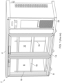
- Figure 1 shows a refrigerator appliance 2 with a frame 4 that houses two cabinets 6,12 with respective doors 8,14.
- the frame also houses a technical cabinet 22 that accommodates the condenser and compressor, and may additionally accommodate the expansion valve.
- the cabinets 6,12 have a shared interior that includes a shelving unit including shelves 18 that are arranged in multiple layers. The shelves 18 are fastened in place at the corners along rails 16 using fasteners or clips, at the front of the cabinet 6,12 and at the back of the cabinet 6,12.
- the present invention provides at least an alternative to refrigerator appliances of the prior art.
- a refrigerator appliance comprising:
- the rear end of the shelf can be supported directly by the integrally moulded shelf support in the panel at the back, instead of using fasteners or clips to attach the panel to a frame structure.
- This increases the available space within the refrigerator appliance for storing and displaying products.
- the position of the panel can be adjusted at the front by the rail and clip arrangement, further simplifying shelf installation.
- the refrigerator appliance of the present invention reduces the time required for installing shelves within the refrigeration cabinet and simplifies the installation process. This is because the number of components required is reduced, and the need for fastening clips or fasteners at the back of the cabinet is removed.
- the first shelf support comprises a plurality of integrally moulded support surfaces.
- the heights of the support surfaces of the first shelf support correspond to the attachment positions of the second shelf support. This allows shelves to be supported by the first and second shelf supports, to position the shelves horizontally.
- adjacent support surfaces are spaced apart by a recess shaped and sized for receiving the shelf.
- the recess extends upwards, towards the top of the cabinet. This advantageously decreases the space required at the front for installing shelves because the shelves can be inserted from the front of the door, from the top in a downwards direction.
- the second shelf support comprises a first rail having a plurality of attachment positions for first clip attachable to one of the plurality of attachment positions of the first rail.
- the rail may be the first rail.
- the second shelf support comprises a second rail having a plurality of attachment positions and a second clip attachable to one of the plurality of attachment positions of the second rail.
- the second shelf support comprises a first rail having a plurality of attachment positions for a first clip attachable to one of the plurality of attachment positions of the first rail, and a second rail having a plurality of attachment positions for a second clip attachable to one of the plurality of attachment positions of the second rail.
- the respective first and second rails are arranged to support a front of the shelf.
- the respective first and second rails are arranged to support a side of the shelf.
- the first rail is arranged to support one of the front and side of the shelf
- the second rail is arranged to support the other of the front and side of the shelf.
- the second shelf support is disposed on or adjacent to a doorpost at the front of the cabinet.
- the first shelf support extends partially over the height of the rear of the cabinet. In examples, the first shelf support extends only partially over the height of the rear of the cabinet. In examples, ends of the first shelf support are spaced from a top and bottom of the cabinet. In examples, the first shelf support is disposed over a middle section of the height of the rear of the cabinet. This increases the available space within the refrigerator appliance.
- the panel is an insulated panel.
- the moulding comprising a moulding that extends across the rear side of the cabinet, and wherein the first shelf support is formed on the moulding.
- the moulding further extends across the top and/or bottom of the cabinet.
- the moulding further extends around at least one side of the cabinet.
- the second shelf support is spaced from the first shelf support along a direction perpendicular to the plane of the door. In examples, the second shelf support is spaced from the first shelf support along a horizontal direction.
- the rail extends vertically. In examples, the rail extends along a direction parallel to the plane of the door.
- the plurality of attachment positions are provided by openings in the rail.
- the refrigerator appliance further comprises a clip (for example the clip), and wherein the clip comprises two protruding arms.
- each arm is attachable to an opening in the rail.
- the first shelf support extends across the width of the rear side of the cabinet.
- the first shelf support extends partially across the width of the rear side of the cabinet. This increases the available space within the refrigerator appliance.
- the first shelf support comprises a first support portion at a first side and a second support portion spaced apart from the first support portion at a second side. This further increases the space available within the refrigerator appliance.
- the refrigerator appliance is a back bar refrigerator appliance.
- a back bar refrigerator appliance is typically sized to fit within a cavity or recess behind a bar, for example under a worksurface and/or between opposing walls.
- the terms 'connected', 'attached', 'coupled', 'mounted' are intended to include direct connections between two members without any other members interposed therebetween, as well as, indirect connections between members in which one or more other members are interposed therebetween.
- the terminology includes the words specifically mentioned above, derivatives thereof, and words of similar import.
- the refrigerator appliance 202 has a cabinet 206 housed within a frame 204, and a door 208 at the front.
- the cabinet 206 has a cuboid shaped interior, having a rear side and an interior side 209 of the door 208 opposite the rear side of the cabinet 206.
- the rear side of the cabinet has a panel 230, with an integrally moulded first shelf support 232.
- the panel 230 may be insulated.
- the panel 230 may be a portion of a moulding that extends around the sides, the top and the bottom of the cabinet 206.
- the first shelf support 232 has a plurality of integrally moulded support surfaces 234.
- the support surfaces 234 are separated by recesses 235 disposed in between adjacent support surfaces 234.
- the first shelf support 232 may be made of a polymer.
- a thermoforming process may be used to form the pattern of support surfaces 234 on the panel 230.
- the refrigerator appliance 202 may be a back bar refrigerator appliance.
- the refrigerator appliance 202 has a second shelf support 236 that is spaced apart from the first shelf support 232 in the cabinet 206.
- the second shelf support 236 has a rail 237 with multiple attachment positions 238 (e.g. openings), and a clip 240 that is attachable to one of the attachment positions 238 so that the clip 240 can support a shelf 218.
- the rear end (219, Figure 4 ) of the shelf 218 is supported by the first shelf support 232 at the rear side of the cabinet 206, and the shelf 218 is supported by the second shelf support 236 on the other side (221, Figure 4 ).
- the clip 240 is attached to one of the attachment positions 238 of the rail 237, so that the shelf 218 is supported by the second shelf support 236 at a position away from the first shelf support 232.
- a fastener 250 is inserted through the shelf 218 and the clip 240 to hold the shelf 218 in place.
- the second shelf support 236 directly engages with and supports the shelf 218 in this example, it is envisaged that the second shelf support 236 may indirectly support the shelf 218.
- the second shelf support 236 may support a horizontal rail (278, Figure 3 ), on which the panel 218 is supported.
- separate second shelf supports 236 support the shelf 218 at the front of the shelf 218, and at the side of the shelf 218.
- FIG. 3 shows the second shelf support 236 in more detail.
- the second shelf support 236 has a rail 237 having a plurality of openings 238 along the length of the rail 237.
- the rail 237 is held vertically.
- a clip 240 is provided that has a bend 242, making the clip 240 V-shaped.
- Each end of the clip 240 has a protruding arm 244 that is inserted through an opening 238 of the rail to hold the clip 240 in place relative to the rail 237.
- the clip 240 has an aperture 246 that aligns with an aperture 279 of a horizontal rail 278.
- a fastener 250 can be inserted through the apertures 246,279 of the respective clip 240 and horizontal rail 278 to hold the clip 240 and rail 278 together.
- a shelf 218 can then be supported by the horizontal rail 278.
- the clip 240 is held on the rail 236 to support the horizontal rail 278 in this example, the clip 240 may instead support the shelf 218 directly.
- Figure 4 shows the installation of a shelf 218 into the cabinet 206 of the refrigerator appliance 202.
- a panel 218 is inserted through the door 208 from the front of the refrigerator appliance 202 in a direction denoted by the arrow 'C', so that a rear side 219 of the shelf 218 is supported by the first shelf support 232 at the rear side of the cabinet 206.
- a front side 221 of the shelf 218 is then lowered in a direction denoted by the arrow 'D', to be supported by the second shelf support 236.
- the recesses 235 provided in the first shelf support 232 may extend upwards.
- the recesses 235 are sized and shaped to receive the shelf 218.
- the shelf 218 is supported at its front 221 or side by a clip 240 that is held in the vertical rail 237.
- a fastener is provided 250 to fasten the clip 240 and the shelf 218 together at attachment positions 238 provided in the rail 237.
- the attachment positions 238 of the vertical rail 237 are aligned with support surfaces 234 of the first shelf support 232 so that the shelf 218 is held in a horizontal position when installed.
- the second shelf support 236 may be provided at the front of the cabinet 206, for example on an interior surface 209 of the door 208.
- the second shelf support 236 may instead or additionally be provided on a side surface of the cabinet 206.
- the first shelf support 232 extends partially over the height of the rear side of the cabinet 206.
- the first shelf support 232 may extend over a middle section of the rear side of the cabinet 206.
- the second shelf support 236 may be arranged to support a front and/or the side of the shelf 218.
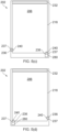
- Figure 5(a) shows second shelf supports 236 that support the front of the shelf 218 at each side.
- One of the second shelf supports 236 is provided next to a doorpost of the refrigerator appliance 202.
- Figure 5(b) shows second shelf supports 236 that support opposing sides of the shelf 218.
- Figure 5(c) shows one second shelf support 236 that supports a left side of the shelf 218, and another second shelf support 236 that supports a front of the shelf 218 on the right.
- Figure 5(d) shows a mirrored arrangement to that of Figure 5(c) , such that one second shelf support 236 supports a right side of the shelf 218, and another second shelf support 236 supports a front side of the shelf 218 on the left.
- Different arrangements of the second shelf support 236 are envisaged, depending on the desired layout of the cabinet 206 of the refrigerator appliance 202.
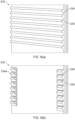
- Figure 6 shows the first shelf support 232 in more detail.
- the first shelf support 232 is integrally moulded and provided on a rear side of the refrigerator cabinet 206.
- Figure 6(a) shows a first arrangement of the first shelf support 232 that extends across the entire width of the rear side of the cabinet 206. This arrangement improves insulation within the cabinet 206.
- the first shelf support 232 has a plurality of integrally moulded support surfaces 234 and recesses 235 separating the support surfaces 234.
- Figure 6(b) shows a different arrangement in which the first shelf support 232 does not extend across the entire width of the rear side of the cabinet 206. Instead, the first shelf support 232 has a first support portion 234a on one side, and a second support portion 234b on the other side that is spaced apart from the first support portion 234b. This arrangement is advantageous because it increases the available space inside the refrigerator appliance 202.
Landscapes
- Engineering & Computer Science (AREA)
- Physics & Mathematics (AREA)
- Thermal Sciences (AREA)
- Chemical & Material Sciences (AREA)
- Combustion & Propulsion (AREA)
- Mechanical Engineering (AREA)
- General Engineering & Computer Science (AREA)
- Refrigerator Housings (AREA)
- Devices That Are Associated With Refrigeration Equipment (AREA)
Abstract
Description
- The invention relates generally to a refrigerator appliance.
- Refrigerator appliances are commonly used to store products such as food and beverages. They are provided with one or more cabinets in which shelves are arranged to store and to place the products for display.
-
Figure 1 shows arefrigerator appliance 2 with a frame 4 that houses twocabinets respective doors 8,14. The frame also houses atechnical cabinet 22 that accommodates the condenser and compressor, and may additionally accommodate the expansion valve. Thecabinets unit including shelves 18 that are arranged in multiple layers. Theshelves 18 are fastened in place at the corners alongrails 16 using fasteners or clips, at the front of thecabinet cabinet - Installing shelving units in such a refrigerator appliance is time-consuming and difficult because the fasteners or clips have to align precisely with the holes provided in the rails. This is especially difficult in for attaching the shelves to the rails at the back of the cabinet, as the area is hard to see and reach. The installation of the shelving unit requires many components to be assembled, which increases assembly time, and takes up the available storage space within the cabinet.
- It would be desirable to provide a refrigerator appliance that addresses the above problems. Particularly, it is an object of the invention to provide a refrigerator appliance that simplifies and reduces the time required for the installation of shelves. It is another object of the invention to reduce the number of components required for installation, and to maximise available space for storing and displaying products within the refrigerator appliance.
- The present invention provides at least an alternative to refrigerator appliances of the prior art.
- In accordance with the present invention there is provided a refrigerator appliance according to the appended claims.
- According to an aspect of the present invention, there is provided a refrigerator appliance, comprising:
- a cabinet comprising a rear side and a door opposite the rear side at a front of the cabinet;
- a panel disposed at the rear side of the cabinet and comprising an integrally moulded first shelf support for supporting a rear end of a shelf; and
- a second shelf support spaced from the first shelf support and arranged to support a front and/or side of the shelf, wherein the second shelf support comprises a rail having a plurality of attachment positions for a clip to support the shelf.
- Thus, the rear end of the shelf can be supported directly by the integrally moulded shelf support in the panel at the back, instead of using fasteners or clips to attach the panel to a frame structure. This increases the available space within the refrigerator appliance for storing and displaying products. Advantageously, the position of the panel can be adjusted at the front by the rail and clip arrangement, further simplifying shelf installation. The refrigerator appliance of the present invention reduces the time required for installing shelves within the refrigeration cabinet and simplifies the installation process. This is because the number of components required is reduced, and the need for fastening clips or fasteners at the back of the cabinet is removed.
- In examples, the first shelf support comprises a plurality of integrally moulded support surfaces. In examples, the heights of the support surfaces of the first shelf support correspond to the attachment positions of the second shelf support. This allows shelves to be supported by the first and second shelf supports, to position the shelves horizontally.
- In examples, adjacent support surfaces are spaced apart by a recess shaped and sized for receiving the shelf. In examples, the recess extends upwards, towards the top of the cabinet. This advantageously decreases the space required at the front for installing shelves because the shelves can be inserted from the front of the door, from the top in a downwards direction.
- In examples, the second shelf support comprises a first rail having a plurality of attachment positions for first clip attachable to one of the plurality of attachment positions of the first rail. For example, the rail may be the first rail.
- In examples, the second shelf support comprises a second rail having a plurality of attachment positions and a second clip attachable to one of the plurality of attachment positions of the second rail.
- In examples, the second shelf support comprises a first rail having a plurality of attachment positions for a first clip attachable to one of the plurality of attachment positions of the first rail, and a second rail having a plurality of attachment positions for a second clip attachable to one of the plurality of attachment positions of the second rail.
- In examples, the respective first and second rails are arranged to support a front of the shelf.
- In examples, the respective first and second rails are arranged to support a side of the shelf.
- In examples, the first rail is arranged to support one of the front and side of the shelf, and the second rail is arranged to support the other of the front and side of the shelf.
- In examples, the second shelf support is disposed on or adjacent to a doorpost at the front of the cabinet.
- In examples, the first shelf support extends partially over the height of the rear of the cabinet. In examples, the first shelf support extends only partially over the height of the rear of the cabinet. In examples, ends of the first shelf support are spaced from a top and bottom of the cabinet. In examples, the first shelf support is disposed over a middle section of the height of the rear of the cabinet. This increases the available space within the refrigerator appliance.
- In examples, the panel is an insulated panel.
- In examples, comprising a moulding that extends across the rear side of the cabinet, and wherein the first shelf support is formed on the moulding. In examples, the moulding further extends across the top and/or bottom of the cabinet. In examples, the moulding further extends around at least one side of the cabinet.
- In examples, the second shelf support is spaced from the first shelf support along a direction perpendicular to the plane of the door. In examples, the second shelf support is spaced from the first shelf support along a horizontal direction.
- In examples, the rail extends vertically. In examples, the rail extends along a direction parallel to the plane of the door.
- In examples, the plurality of attachment positions are provided by openings in the rail.
- In examples, the refrigerator appliance further comprises a clip (for example the clip), and wherein the clip comprises two protruding arms. In examples, each arm is attachable to an opening in the rail.
- In examples, the first shelf support extends across the width of the rear side of the cabinet.
- In examples, the first shelf support extends partially across the width of the rear side of the cabinet. This increases the available space within the refrigerator appliance.
- In examples, the first shelf support comprises a first support portion at a first side and a second support portion spaced apart from the first support portion at a second side. This further increases the space available within the refrigerator appliance.
- In examples, the refrigerator appliance is a back bar refrigerator appliance. A back bar refrigerator appliance is typically sized to fit within a cavity or recess behind a bar, for example under a worksurface and/or between opposing walls.
- Embodiments of the invention are now described, by way of example only, hereinafter with reference to the accompanying drawings, in which:
- Figure 1
- illustrates a perspective view of a known refrigerator appliance;
- Figure 2
- illustrates a schematic representation of a refrigerator appliance;
- Figure 3
- illustrates the attachment of a clip on a rail for supporting a shelf;
- Figure 4
- illustrates a schematic representation of the refrigerator appliance of
Figure 2 , showing the installation of a shelf; - Figure 5
- illustrates a schematic representation of a refrigerator appliance, showing the arrangement clips and rails: (a) in a first configuration; (b) in a second configuration; (c) in a third configuration; and (d) in a fourth configuration;
- Figure 6
- illustrates a perspective view of a first shelf support on a back panel of a refrigerator appliance: (a) in a first configuration, and (b) in a second configuration.
- Certain terminology is used in the following description for convenience only and is not limiting. The words 'right', 'left', 'lower', 'upper', 'front', 'rear', 'upward', 'down' and 'downward' designate directions in the drawings to which reference is made and are with respect to the described component when assembled and mounted. The words 'inner', 'inwardly' and 'outer', 'outwardly' refer to directions toward and away from, respectively, a designated centreline or a geometric centre of an element being described (e.g. central axis), the particular meaning being readily apparent from the context of the description.
- Further, as used herein, the terms 'connected', 'attached', 'coupled', 'mounted' are intended to include direct connections between two members without any other members interposed therebetween, as well as, indirect connections between members in which one or more other members are interposed therebetween. The terminology includes the words specifically mentioned above, derivatives thereof, and words of similar import.
- Further, unless otherwise specified, the use of ordinal adjectives, such as, "first", "second", "third" etc. merely indicate that different instances of like objects are being referred to and are not intended to imply that the objects so described must be in a given sequence, either temporally, spatially, in ranking or in any other manner.
- Like reference numerals are used to depict like features throughout.
- Referring now to
Figure 2 , there is shown arefrigerator appliance 202. Therefrigerator appliance 202 has acabinet 206 housed within aframe 204, and adoor 208 at the front. Thecabinet 206 has a cuboid shaped interior, having a rear side and aninterior side 209 of thedoor 208 opposite the rear side of thecabinet 206. The rear side of the cabinet has apanel 230, with an integrally mouldedfirst shelf support 232. Thepanel 230 may be insulated. Thepanel 230 may be a portion of a moulding that extends around the sides, the top and the bottom of thecabinet 206. In this example, thefirst shelf support 232 has a plurality of integrally moulded support surfaces 234. The support surfaces 234 are separated byrecesses 235 disposed in between adjacent support surfaces 234. Thefirst shelf support 232 may be made of a polymer. A thermoforming process may be used to form the pattern of support surfaces 234 on thepanel 230. Therefrigerator appliance 202 may be a back bar refrigerator appliance. - The
refrigerator appliance 202 has asecond shelf support 236 that is spaced apart from thefirst shelf support 232 in thecabinet 206. Thesecond shelf support 236 has arail 237 with multiple attachment positions 238 (e.g. openings), and aclip 240 that is attachable to one of the attachment positions 238 so that theclip 240 can support ashelf 218. When assembled, the rear end (219,Figure 4 ) of theshelf 218 is supported by thefirst shelf support 232 at the rear side of thecabinet 206, and theshelf 218 is supported by thesecond shelf support 236 on the other side (221,Figure 4 ). In particular, theclip 240 is attached to one of the attachment positions 238 of therail 237, so that theshelf 218 is supported by thesecond shelf support 236 at a position away from thefirst shelf support 232. In this example, afastener 250 is inserted through theshelf 218 and theclip 240 to hold theshelf 218 in place. Although thesecond shelf support 236 directly engages with and supports theshelf 218 in this example, it is envisaged that thesecond shelf support 236 may indirectly support theshelf 218. For example, thesecond shelf support 236 may support a horizontal rail (278,Figure 3 ), on which thepanel 218 is supported. In this example, separate second shelf supports 236 support theshelf 218 at the front of theshelf 218, and at the side of theshelf 218. -
Figure 3 shows thesecond shelf support 236 in more detail. Thesecond shelf support 236 has arail 237 having a plurality ofopenings 238 along the length of therail 237. Therail 237 is held vertically. Aclip 240 is provided that has abend 242, making the clip 240 V-shaped. Each end of theclip 240 has aprotruding arm 244 that is inserted through anopening 238 of the rail to hold theclip 240 in place relative to therail 237. Theclip 240 has anaperture 246 that aligns with anaperture 279 of ahorizontal rail 278. Afastener 250 can be inserted through the apertures 246,279 of therespective clip 240 andhorizontal rail 278 to hold theclip 240 andrail 278 together. Ashelf 218 can then be supported by thehorizontal rail 278. Although theclip 240 is held on therail 236 to support thehorizontal rail 278 in this example, theclip 240 may instead support theshelf 218 directly. -
Figure 4 shows the installation of ashelf 218 into thecabinet 206 of therefrigerator appliance 202. Apanel 218 is inserted through thedoor 208 from the front of therefrigerator appliance 202 in a direction denoted by the arrow 'C', so that arear side 219 of theshelf 218 is supported by thefirst shelf support 232 at the rear side of thecabinet 206. Afront side 221 of theshelf 218 is then lowered in a direction denoted by the arrow 'D', to be supported by thesecond shelf support 236. Therecesses 235 provided in thefirst shelf support 232 may extend upwards. Therecesses 235 are sized and shaped to receive theshelf 218. Theshelf 218 is supported at itsfront 221 or side by aclip 240 that is held in thevertical rail 237. A fastener is provided 250 to fasten theclip 240 and theshelf 218 together at attachment positions 238 provided in therail 237. In this example, the attachment positions 238 of thevertical rail 237 are aligned withsupport surfaces 234 of thefirst shelf support 232 so that theshelf 218 is held in a horizontal position when installed. Thesecond shelf support 236 may be provided at the front of thecabinet 206, for example on aninterior surface 209 of thedoor 208. Thesecond shelf support 236 may instead or additionally be provided on a side surface of thecabinet 206. In this example, thefirst shelf support 232 extends partially over the height of the rear side of thecabinet 206. Thefirst shelf support 232 may extend over a middle section of the rear side of thecabinet 206. - As shown in
Figure 5 , thesecond shelf support 236 may be arranged to support a front and/or the side of theshelf 218.Figure 5(a) shows second shelf supports 236 that support the front of theshelf 218 at each side. One of the second shelf supports 236 is provided next to a doorpost of therefrigerator appliance 202.Figure 5(b) shows second shelf supports 236 that support opposing sides of theshelf 218.Figure 5(c) shows onesecond shelf support 236 that supports a left side of theshelf 218, and anothersecond shelf support 236 that supports a front of theshelf 218 on the right.Figure 5(d) shows a mirrored arrangement to that ofFigure 5(c) , such that onesecond shelf support 236 supports a right side of theshelf 218, and anothersecond shelf support 236 supports a front side of theshelf 218 on the left. Different arrangements of thesecond shelf support 236 are envisaged, depending on the desired layout of thecabinet 206 of therefrigerator appliance 202. -
Figure 6 shows thefirst shelf support 232 in more detail. Thefirst shelf support 232 is integrally moulded and provided on a rear side of therefrigerator cabinet 206. -
Figure 6(a) shows a first arrangement of thefirst shelf support 232 that extends across the entire width of the rear side of thecabinet 206. This arrangement improves insulation within thecabinet 206. Thefirst shelf support 232 has a plurality of integrally moulded support surfaces 234 and recesses 235 separating the support surfaces 234.Figure 6(b) shows a different arrangement in which thefirst shelf support 232 does not extend across the entire width of the rear side of thecabinet 206. Instead, thefirst shelf support 232 has afirst support portion 234a on one side, and a second support portion 234b on the other side that is spaced apart from the first support portion 234b. This arrangement is advantageous because it increases the available space inside therefrigerator appliance 202. - It will be appreciated by persons skilled in the art that the above detailed examples have been described by way of example only and not in any limitative sense, and that various alterations and modifications are possible without departing from the scope of the invention as defined by the appended claims. Various modifications to the detailed examples described above are possible.
- Through the description and claims of this specification, the words "comprise" and "contain" and variations of them mean "including but not limited to", and they are not intended to (and do not) exclude other moieties, additives, components, integers or steps. Throughout the description and claims of this specification, the singular encompasses the plural unless the context otherwise requires. In particular, where the indefinite article is used, the specification is to be understood as contemplating plurality as well as singularity, unless the context requires otherwise.
- Features, integers, characteristics, compounds, chemical moieties or groups described in conjunction with a particular aspect, embodiment or example of the invention are to be understood to be applicable to any other aspect, embodiment or example described herein unless incompatible therewith. All of the features disclosed in this specification (including any accompanying claims, abstract and drawings), and/or all of the steps of any method or process so disclosed, may be combined in any combination, except combinations where at least some of such features and/or steps are mutually exclusive. The invention is not restricted to the details of any foregoing embodiments. The invention extends to any novel one, or any novel combination, of the features disclosed in this specification (including any accompanying claims, abstract or drawings), or to any novel one, or any novel combination, of the steps of any method or process so disclosed.
- It will be appreciated by persons skilled in the art that the above embodiment(s) have been described by way of example only and not in any limitative sense, and that various alterations and modifications are possible without departing from the scope of the invention as defined by the appended claims. Various modifications to the detailed designs as described above are possible.
- Aspects of the disclosure are set out in the following numbered clauses:
- Clause 1. A refrigerator appliance, comprising:
- a cabinet comprising a rear side and a door opposite the rear side at a front of the cabinet;
- a panel disposed at the rear side of the cabinet and comprising an integrally moulded first shelf support for supporting a rear end of a shelf; and
- a second shelf support spaced from the first shelf support and arranged to support a front and/or side of the shelf, wherein the second shelf support comprises a rail having a plurality of attachment positions for a clip to support the shelf.
-
Clause 2. A refrigerator appliance according to clause 1, wherein the first shelf support comprises a plurality of integrally moulded support surfaces. - Clause 3. A refrigerator appliance according to
clause 2, wherein the heights of the support surfaces of the first shelf support correspond to the attachment positions of the second shelf support. - Clause 4. A refrigerator appliance according to
clause 2 or clause 3, wherein adjacent support surfaces are spaced apart by a recess shaped and sized for receiving the shelf. - Clause 5. A refrigerator appliance according to any one of clause 1 to clause 4, wherein the second shelf support comprises a first rail having a plurality of attachment positions for a first clip attachable to one of the plurality of attachment positions of the first rail, and a second rail having a plurality of attachment positions for a second clip attachable to one of the plurality of attachment positions of the second rail.
-
Clause 6. A refrigerator appliance according to clause 5, wherein the respective first and second rails are arranged to support a front of the shelf. - Clause 7. A refrigerator appliance according to clause 5, wherein the respective first and second rails are arranged to support a side of the shelf.
- Clause 8. A refrigerator appliance according to clause 5, wherein the first rail is arranged to support one of the front and side of the shelf, and the second rail is arranged to support the other of the front and side of the shelf.
- Clause 9. A refrigerator appliance according to any one of clause 1 to clause 8, wherein the second shelf support is disposed on or adjacent to a doorpost at the front of the cabinet.
-
Clause 10. A refrigerator appliance according to any one of clause 1 to clause 9, wherein the first shelf support extends partially over the height of the rear side of the cabinet. - Clause 11. A refrigerator appliance according to any one of clause 1 to
clause 10, wherein ends of the first shelf support are spaced from a top and bottom of the cabinet. -
Clause 12. A refrigerator appliance according to any one clause 1 to clause 11, wherein the panel is an insulated panel. - Clause 13. A refrigerator appliance according to any one of clause 1 to
clause 12, comprising a moulding that extends across the rear side of the cabinet, and wherein the first shelf support is formed on the moulding -
Clause 14. A refrigerator appliance according to clause 13, wherein the moulding further extends across the top and/or bottom of the cabinet. - Clause 15. A refrigerator appliance according to clause 13 or
clause 14, wherein the moulding further extends around at least one side of the cabinet. -
Clause 16. A refrigerator appliance according to any one of clause 1 to clause 15, wherein the plurality of attachment positions are provided by openings in the rail. - Clause 17. A refrigerator according to
clause 16, further comprising a clip for the second shelf support, and wherein the clip comprises two protruding arms, each arm being attachable to an opening in the rail. -
Clause 18. A refrigerator appliance according to any one of clause 1 to clause 17, wherein the first shelf support extends across the width of the rear side of the cabinet. - Clause 19. A refrigerator appliance according to any one of clauses 1 to 17, wherein the first shelf support extends partially across the width of the rear side of the cabinet.
- Clause 20. A refrigerator appliance according to any one of clause 1 to clause 19, wherein the first shelf support comprises a first support portion at a first side and a second support portion spaced apart from the first support portion at a second side.
- Clause 21. A refrigerator appliance according to any one of clause 1 to clause 20, wherein the refrigerator appliance is a back bar refrigerator appliance.
Claims (15)
- A refrigerator appliance, comprising:a cabinet comprising a rear side and a door opposite the rear side at a front of the cabinet;a panel disposed at the rear side of the cabinet and comprising an integrally moulded first shelf support for supporting a rear end of a shelf; anda second shelf support spaced from the first shelf support and arranged to support a front and/or side of the shelf, wherein the second shelf support comprises a rail having a plurality of attachment positions for a clip to support the shelf.
- A refrigerator appliance according to claim 1, wherein the first shelf support comprises a plurality of integrally moulded support surfaces, optionally wherein the heights of the support surfaces of the first shelf support correspond to the attachment positions of the second shelf support.
- A refrigerator appliance according to claim 2, wherein adjacent support surfaces are spaced apart by a recess shaped and sized for receiving the shelf.
- A refrigerator appliance according to any one of the preceding claims, wherein the second shelf support comprises a first rail having a plurality of attachment positions for a first clip attachable to one of the plurality of attachment positions of the first rail, and a second rail having a plurality of attachment positions for a second clip attachable to one of the plurality of attachment positions of the second rail.
- A refrigerator appliance according to claim 4, wherein the respective first and second rails are arranged to support a front of the shelf, orwherein the respective first and second rails are arranged to support a side of the shelf, orwherein the first rail is arranged to support one of the front and side of the shelf, and the second rail is arranged to support the other of the front and side of the shelf.
- A refrigerator appliance according to any one of the preceding claims, wherein the second shelf support is disposed on or adjacent to a doorpost at the front of the cabinet.
- A refrigerator appliance according to any one of the preceding claims, wherein the first shelf support extends partially over the height of the rear side of the cabinet.
- A refrigerator appliance according to any one of the preceding claims, wherein ends of the first shelf support are spaced from a top and bottom of the cabinet.
- A refrigerator appliance according to any one of the preceding claims, wherein the panel is an insulated panel.
- A refrigerator appliance according to any one of the preceding claims, comprising a moulding that extends across the rear side of the cabinet, and wherein the first shelf support is formed on the moulding, optionally wherein the moulding further extends across the top and/or bottom of the cabinet, and optionally wherein the moulding further extends around at least one side of the cabinet.
- A refrigerator appliance according to any one of the preceding claims, wherein the plurality of attachment positions are provided by openings in the rail, and optionally wherein the refrigerator appliance further comprises a clip for the second shelf support, and wherein the clip comprises two protruding arms, each arm being attachable to an opening in the rail.
- A refrigerator appliance according to any one of the preceding claims, wherein the first shelf support extends across the width of the rear side of the cabinet.
- A refrigerator appliance according to any one of claims 1 to 11, wherein the first shelf support extends partially across the width of the rear side of the cabinet.
- A refrigerator appliance according to any one of the preceding claims, wherein the first shelf support comprises a first support portion at a first side and a second support portion spaced apart from the first support portion at a second side.
- A refrigerator appliance according to any one of the preceding claims, wherein the refrigerator appliance is a back bar refrigerator appliance.
Applications Claiming Priority (1)
| Application Number | Priority Date | Filing Date | Title |
|---|---|---|---|
| GB2311021.6A GB2631958A (en) | 2023-07-19 | 2023-07-19 | Refrigerator appliance |
Publications (1)
| Publication Number | Publication Date |
|---|---|
| EP4494525A1 true EP4494525A1 (en) | 2025-01-22 |
Family
ID=87758590
Family Applications (1)
| Application Number | Title | Priority Date | Filing Date |
|---|---|---|---|
| EP24189523.4A Pending EP4494525A1 (en) | 2023-07-19 | 2024-07-18 | Refrigerator appliance |
Country Status (3)
| Country | Link |
|---|---|
| US (1) | US20250024966A1 (en) |
| EP (1) | EP4494525A1 (en) |
| GB (1) | GB2631958A (en) |
Citations (3)
| Publication number | Priority date | Publication date | Assignee | Title |
|---|---|---|---|---|
| KR19990000954U (en) * | 1997-06-13 | 1999-01-15 | 최진호 | Showcase |
| WO2007033962A1 (en) * | 2005-09-22 | 2007-03-29 | BSH Bosch und Siemens Hausgeräte GmbH | Refrigerator with a divided shelf |
| WO2013164176A2 (en) * | 2012-05-04 | 2013-11-07 | Miele & Cie. Kg | Contact arrangement and refrigerator, freezer or wine storage cabinet |
Family Cites Families (19)
| Publication number | Priority date | Publication date | Assignee | Title |
|---|---|---|---|---|
| CA772057A (en) * | 1967-11-21 | R. Klotz David | Refrigerator cabinet storage compartment construction | |
| US3266858A (en) * | 1964-03-12 | 1966-08-16 | American Motors Corp | Refrigerator cabinet storage compartment construction |
| US3797903A (en) * | 1972-10-25 | 1974-03-19 | Traulsen & Co Inc | Refrigerator including shelf mounting apparatus |
| US5893620A (en) * | 1993-07-26 | 1999-04-13 | Whirlpool Corporation | Multiple shelf support system in common refrigerator liner |
| US5645182A (en) * | 1994-10-11 | 1997-07-08 | Paul Flum Ideas, Inc. | Adjustable shelf support structure |
| US5642924A (en) * | 1996-02-29 | 1997-07-01 | White Consolidated Industries, Inc. | Shelf system for a refrigerator cabinet |
| US6238032B1 (en) * | 1999-05-21 | 2001-05-29 | Victory Refrigeration Company | Refrigerated cabinet with molded liner |
| KR20040065368A (en) * | 2003-01-14 | 2004-07-22 | 삼성전자주식회사 | Shelf of refrigerator, Fixing unit for shelf of refrigerator and refrigerator |
| US7533948B2 (en) * | 2004-05-05 | 2009-05-19 | Manitowoc Foodservice Companies, Inc. | Adjustable shelving system |
| US9366470B2 (en) * | 2011-12-22 | 2016-06-14 | Bsh Home Appliances Corporation | Cantilevered shelving rack |
| US8960827B2 (en) * | 2012-08-24 | 2015-02-24 | Ssw Holding Company, Inc. | Anti-tip and retention assembly for appliance support plate |
| US9357840B2 (en) * | 2014-07-31 | 2016-06-07 | ADCO Industries—Technologies, L.P. | Supporting consumer products |
| BR102014020160B1 (en) * | 2014-08-14 | 2022-02-15 | Electrolux Do Brasil S.A. | Telescopic accessory applied to refrigerator door or similar |
| US10281197B2 (en) * | 2016-10-11 | 2019-05-07 | Whirlpool Corporation | Quick shelf adjustment mechanism for a refrigerating appliance |
| CA2984523A1 (en) * | 2016-10-31 | 2018-04-30 | Berk B. Adanur | Modular storage container |
| US20180363974A1 (en) * | 2017-06-14 | 2018-12-20 | Whirlpool Corporation | Adjustable mullion assembly |
| US10827833B2 (en) * | 2018-03-22 | 2020-11-10 | Intermetro Industries Corporation | Cabinet with tiltable wire shelf and bin exchange system |
| US11725872B2 (en) * | 2019-01-12 | 2023-08-15 | Zhongshan Haile Electric Appliance Co., Ltd | Support frame for sliding adjustment shelves of refrigerated cabinet |
| US12345465B2 (en) * | 2023-03-28 | 2025-07-01 | Whirlpool Corporation | Refrigerator appliance shelving system |
-
2023
- 2023-07-19 GB GB2311021.6A patent/GB2631958A/en active Pending
-
2024
- 2024-07-18 EP EP24189523.4A patent/EP4494525A1/en active Pending
- 2024-07-19 US US18/777,651 patent/US20250024966A1/en active Pending
Patent Citations (3)
| Publication number | Priority date | Publication date | Assignee | Title |
|---|---|---|---|---|
| KR19990000954U (en) * | 1997-06-13 | 1999-01-15 | 최진호 | Showcase |
| WO2007033962A1 (en) * | 2005-09-22 | 2007-03-29 | BSH Bosch und Siemens Hausgeräte GmbH | Refrigerator with a divided shelf |
| WO2013164176A2 (en) * | 2012-05-04 | 2013-11-07 | Miele & Cie. Kg | Contact arrangement and refrigerator, freezer or wine storage cabinet |
Also Published As
| Publication number | Publication date |
|---|---|
| US20250024966A1 (en) | 2025-01-23 |
| GB2631958A (en) | 2025-01-22 |
| GB202311021D0 (en) | 2023-08-30 |
Similar Documents
| Publication | Publication Date | Title |
|---|---|---|
| CA1295141C (en) | Appliance door having a module support system, method of making, and module | |
| US5004302A (en) | Shelf support system for split cantilever shelves | |
| US12342938B2 (en) | Trim assembly for an appliance shelf | |
| US20090009982A1 (en) | Electrical component mounting assembly | |
| US5361599A (en) | Refrigerator shelf ladder fastener | |
| EP3051977A1 (en) | Shelving system | |
| US6238032B1 (en) | Refrigerated cabinet with molded liner | |
| KR102402897B1 (en) | Drawer mounting structure of drawer type refrigerator | |
| EP4411295A1 (en) | Refrigerator appliance with two half shelves supported by a cantilever arm | |
| US4829653A (en) | Method of making an appliance door having a module support system | |
| US20250024966A1 (en) | Refrigerator appliance | |
| US11067331B1 (en) | Cantilever shelf and shelf support assembly | |
| US12345465B2 (en) | Refrigerator appliance shelving system | |
| KR100983283B1 (en) | Shelf support and refrigerator with him | |
| US11555647B2 (en) | Rear bracket for shelf assembly | |
| US7401489B2 (en) | Method of forming a one-piece frame for a cantilevered refrigerator shelf | |
| CN115307357A (en) | Refrigerating appliance | |
| EP1881281A9 (en) | Built-in refrigerator with increased internal volume | |
| US11976875B2 (en) | Refrigerator | |
| JPH1183304A (en) | Cooling refrigerator | |
| KR200495198Y1 (en) | Shelf stand | |
| US20240035738A1 (en) | Cooling device with a center pillar and a rail fixation assembly | |
| JPH08145556A (en) | Shelf device of storing chamber having no pillar | |
| KR20040029852A (en) | Body assembly using adiabatic panel for refrigerator/show-case and manufacturing method thereof | |
| KR20230132219A (en) | Refrigerator |
Legal Events
| Date | Code | Title | Description |
|---|---|---|---|
| PUAI | Public reference made under article 153(3) epc to a published international application that has entered the european phase |
Free format text: ORIGINAL CODE: 0009012 |
|
| STAA | Information on the status of an ep patent application or granted ep patent |
Free format text: STATUS: THE APPLICATION HAS BEEN PUBLISHED |
|
| AK | Designated contracting states |
Kind code of ref document: A1 Designated state(s): AL AT BE BG CH CY CZ DE DK EE ES FI FR GB GR HR HU IE IS IT LI LT LU LV MC ME MK MT NL NO PL PT RO RS SE SI SK SM TR |
|
| STAA | Information on the status of an ep patent application or granted ep patent |
Free format text: STATUS: REQUEST FOR EXAMINATION WAS MADE |
|
| 17P | Request for examination filed |
Effective date: 20250718 |
|
| STAA | Information on the status of an ep patent application or granted ep patent |
Free format text: STATUS: EXAMINATION IS IN PROGRESS |
|
| 17Q | First examination report despatched |
Effective date: 20250929 |