EP4494524A1 - Refrigeration display cabinet - Google Patents
Refrigeration display cabinet Download PDFInfo
- Publication number
- EP4494524A1 EP4494524A1 EP24189251.2A EP24189251A EP4494524A1 EP 4494524 A1 EP4494524 A1 EP 4494524A1 EP 24189251 A EP24189251 A EP 24189251A EP 4494524 A1 EP4494524 A1 EP 4494524A1
- Authority
- EP
- European Patent Office
- Prior art keywords
- wind deflector
- air channel
- evaporator
- opening
- display cabinet
- Prior art date
- Legal status (The legal status is an assumption and is not a legal conclusion. Google has not performed a legal analysis and makes no representation as to the accuracy of the status listed.)
- Withdrawn
Links
Images

Classifications
-
- A—HUMAN NECESSITIES
- A47—FURNITURE; DOMESTIC ARTICLES OR APPLIANCES; COFFEE MILLS; SPICE MILLS; SUCTION CLEANERS IN GENERAL
- A47F—SPECIAL FURNITURE, FITTINGS, OR ACCESSORIES FOR SHOPS, STOREHOUSES, BARS, RESTAURANTS OR THE LIKE; PAYING COUNTERS
- A47F3/00—Show cases or show cabinets
- A47F3/04—Show cases or show cabinets air-conditioned, refrigerated
- A47F3/0439—Cases or cabinets of the open type
- A47F3/0443—Cases or cabinets of the open type with forced air circulation
- A47F3/0447—Cases or cabinets of the open type with forced air circulation with air curtains
Definitions
- the present invention relates to the technical field of refrigeration equipment, in particular to a refrigeration display cabinet.
- refrigeration display cabinets mainly appear as containers in the market and are the essential facilities for large shopping malls, supermarkets, and the catering industry. They can store and display dairy products, beverages, fruits, meat products, etc. at different temperatures.
- FIGS. 1 and 2 The structure of an existing refrigeration display cabinet is shown in FIGS. 1 and 2 .
- the body of a refrigeration display cabinet 10 is a cabinet 11, which is configured with an air channel 12, a fan 13, and an evaporator 14.
- a partition 15 separates the air channel 12 into an inner air channel 12a and an outer air channel 12b.
- the fan 13 is arranged at or near the bottom of the partition 15 to blow air into the air channel 12, and the evaporator 14 is arranged in the inner air channel 12a.
- the evaporator 14 in the inner air channel 12a is prone to frost formation. Due to the presence of frost, the airflow entering the evaporator 14 is reduced, which affects the refrigeration effect and can easily cause temperature-sensitive products to spoil, causing losses to merchants and potentially leading to customers purchasing spoiled products. Therefore, it is necessary to further improve the refrigeration display cabinets.
- the present invention provides a refrigeration display cabinet, so as to solve or at least alleviate one or more of the aforementioned problems and problems in other aspects existing in the prior art, or to provide an alternative technical solution for the prior art.
- a refrigeration display cabinet comprising:
- the damper assembly comprises a plurality of wind deflectors, wherein the plurality of wind deflectors are rotatably fixed at the opening, and the plurality of wind deflectors synchronously open or close the opening by means of a linkage mechanism.
- the plurality of wind deflectors comprise a first wind deflector, a second wind deflector, and a third wind deflector, wherein the first wind deflector is arranged at or near the top of the evaporator, the second wind deflector is arranged in or near the middle of the evaporator, and the third wind deflector is arranged at or near the bottom of the evaporator.
- the length of the second wind deflector is the same as that of the third wind deflector, and the lengths of the second wind deflector and the third wind deflector are less than the length of the first wind deflector
- the widths of the first wind deflector, the second wind deflector, and the third wind deflector are the same as the width of the outer air channel in the horizontal direction.
- the length of the first wind deflector is less than the length of the outer air channel in the horizontal direction
- the first wind deflector, the second wind deflector, and the third wind deflector are made of metal or plastic.
- the shape of the opening is consistent with the shape of the side of the evaporator.
- the first wind deflector, the second wind deflector, and the third wind deflector are controlled by a stepper motor controller.
- the damper assembly is fixed at the opening of the partition by bolts.
- the refrigeration display cabinet further comprises a fan arranged at or near the bottom of the partition.
- the refrigeration display cabinet of the present invention adopts a design of air intake simultaneously from the side and bottom of the evaporator, which makes the direct air intake area of the evaporator larger during the defrosting mode, thus greatly improving the heat exchange efficiency and achieving better defrosting effect.
- any technical features or solutions in the embodiments are one or several of multiple optional technical features or technical solutions.
- refrigeration display cabinets are widely used to display goods that require refrigeration, mainly for achieving refrigerated storage of goods and displaying some goods that require low-temperature storage to consumers.
- refrigeration display cabinets are usually open, using air curtains to separate the food from the outside environment to reduce the entry of hot air.
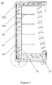
- FIG. 3 schematically illustrates the structure of an embodiment of a refrigeration display cabinet according to the present invention in general.
- a refrigeration display cabinet 100 is composed of a cabinet 110, a display rack 120, an air channel 130, a partition 140, an evaporator 150, and a damper assembly 160, among other parts.
- the display rack 120 is fixed inside the cabinet 110 for storing and displaying various commodities such as dairy products, beverages, fruits, meat products, etc., and the air channel 130 is arranged at least partially surrounding the display rack 120.
- the partition 140 is mounted in the air channel 130 to separate the air channel 130 into an inner air channel 131 and an outer air channel 132, wherein the inner air channel 131 is closer to the display rack 120 relative to the outer air channel 132.
- the refrigeration display cabinet 100 may further comprise a fan 170, which is provided at or near the bottom of the partition 140.
- the partition 140 is also provided with an opening for connecting the inner air channel 131 and the outer air channel 132.
- the evaporator 150 is arranged in the inner air channel 131, and the side of the evaporator 150 is located at or near the opening.
- the damper assembly 160 can be fixed to the opening of the partition 140 by bolts or other means, wherein the damper assembly 160 can open or close the opening. Therefore, during the defrosting mode of the refrigeration display cabinet, air can not only enter from the bottom of the evaporator but also from the side of the evaporator. By increasing the air intake area, the heat transfer efficiency can be significantly improved, thereby accelerating the defrosting process.
- the external air enters the air channel 130 of the refrigeration display cabinet 100, it is divided into two streams of airflow through the partition 140, i.e., one stream of airflow flows through the evaporator 150 in the inner air channel 131, and forms a refrigeration airflow through heat exchange to cool the goods on the display rack 120; another stream of airflow flows in the outer air channel 132 to protect the air curtain on the inner side of the inner air channel 131 from being exposed to the environment, thereby achieving the goal of energy conservation.
- Two streams of airflow leave from the holes on the air outlet plate of the air channel 130 and blow downwards, returning to the cabinet 110 from the return air inlet. It can thus be seen that in the refrigeration display cabinet 100, the air forms an "air curtain" surrounding the display rack 120.
- the defrosting mode when the external air enters the air channel 130 of the cabinet 110, it is divided into two streams of airflow through the partition 140, i.e., one stream of airflow flows through the evaporator 150 in the inner air channel 131 to defrost from the bottom of the evaporator 150; at the same time, the damper assembly 160 opens the opening, allowing another stream of airflow to flow into the side of the evaporator 150 through the opening in the outer air channel 132, so as to defrost from the side of the evaporator 150.
- Two streams of airflow converge at the evaporator 150 to form one stream of airflow, which leaves from the holes on the air outlet plate of the air channel 130 and blows downwards, and then returns to the cabinet 110 from the return air inlet.
- the directions of the airflow during defrosting are shown by the arrows in FIG. 3 .
- the damper assembly 160 comprises a plurality of wind deflectors, which are rotatably fixed at the opening, and the plurality of wind deflectors can synchronously open or close the opening by means of a linkage mechanism (not shown).
- a linkage mechanism not shown.
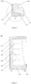
- the plurality of wind deflectors comprise a first wind deflector 161, a second wind deflector 162, and a third wind deflector 163, wherein the first wind deflector 161 can be arranged at or near the top of the evaporator 150, the second wind deflector 162 can be arranged in or near the middle of the evaporator 150, and the third wind deflector 163 can be arranged at or near the bottom of the evaporator 150, as shown in FIG. 4 .
- the length of the second wind deflector 162 is the same as that of the third wind deflector 163, and the length of the second wind deflector 162 and that of the third wind deflector 163 are less than the length of the first wind deflector 161, so that air is introduced from the side of the evaporator from bottom to top during the defrosting mode.
- the length of the first wind deflector 161 can be designed to be less than the length of the outer air channel 132 in the horizontal direction.
- the second wind deflector 162 and the third wind deflector 163 can rotate to the same inclined position as the first wind deflector 161 (see FIGS. 3 and 4 ), which is very conducive to guiding the air smoothly into the side of the evaporator 150.
- the widths of the first wind deflector 161, the second wind deflector 162, and the third wind deflector 163 can be designed to be the same as the width of the outer air channel 132 in the horizontal direction (i.e., perpendicular to the paper direction). It is also readily conceivable to those skilled in the art that the first wind deflector 161, the second wind deflector 162, and the third wind deflector 163 can all be made of materials such as metal or plastic.
- the first wind deflector 161, the second wind deflector 162, and the third wind deflector 163 can be controlled by a stepper motor controller (not shown). It should be noted that the stepper motor controller can control the rotation angle and rotation direction of the first wind deflector 161, the second wind deflector 162, and the third wind deflector 163, so that the damper assembly 160 can synchronously open or close the opening as needed.
- the shape of the opening is consistent with the shape of the side of the evaporator 150. That is to say, the air intake area on the side of the evaporator 150 is the same as the area of the side of the evaporator 150, so that the entire side of the evaporator 150 directly participates in heat exchange, which is conducive to accelerating the defrosting process of the evaporator 150.
- the refrigeration display cabinet of the present invention adopts a design of air intake simultaneously from the side and the bottom of the evaporator, which makes the direct air intake area of the evaporator larger during the defrosting mode, thus further improving the heat exchange efficiency and achieving better defrosting effect.
- any component provided by the present invention can be either assembled from multiple individual components or manufactured as a separate component using an integration process.
- orientations or positional relationships indicated by the above terms are based on the orientations or positional relationships shown in the drawings. These terms are used merely for the convenience of describing the present invention and simplifying the description, rather than indicating or implying that the device, mechanism, component or element referred to must have a specific orientation, be constructed and operated in a specific orientation, so they cannot be understood as forming limitations on the scope of protection of the present invention.
Landscapes
- Physics & Mathematics (AREA)
- Thermal Sciences (AREA)
- Freezers Or Refrigerated Showcases (AREA)
Abstract
The present invention proposes a refrigeration display cabinet, comprising: a cabinet; a display rack fixed inside the cabinet; an air channel arranged at least partially surrounding the display rack; a partition mounted in the air channel to separate the air channel into an inner air channel and an outer air channel, wherein the partition is provided with an opening for connecting the inner air channel and the outer air channel; an evaporator arranged in the inner air channel, wherein the side of the evaporator is located at or near the opening; and a damper assembly fixed at the opening of the partition, wherein the damper assembly is capable of opening or closing the opening. The refrigeration display cabinet according to the present invention can defrost the evaporator simultaneously from the bottom and side thereof during the defrosting mode, thus improving defrosting efficiency.
Description
- The present invention relates to the technical field of refrigeration equipment, in particular to a refrigeration display cabinet.
- As an important carrier for food sales, refrigeration display cabinets mainly appear as containers in the market and are the essential facilities for large shopping malls, supermarkets, and the catering industry. They can store and display dairy products, beverages, fruits, meat products, etc. at different temperatures.
- The structure of an existing refrigeration display cabinet is shown in
FIGS. 1 and2 . The body of arefrigeration display cabinet 10 is acabinet 11, which is configured with anair channel 12, afan 13, and anevaporator 14. Apartition 15 separates theair channel 12 into aninner air channel 12a and anouter air channel 12b. Thefan 13 is arranged at or near the bottom of thepartition 15 to blow air into theair channel 12, and theevaporator 14 is arranged in theinner air channel 12a. When external air enters theair channel 12 of thecabinet 11, it is divided into two streams of airflow through thepartition 15, i.e., one stream of airflow flow through theevaporator 14 in theinner air channel 12a and becomes a low-temperature airflow through heat exchange to cool the goods on adisplay rack 16; another stream of airflow flows in theouter air channel 12b to protect the air curtain of theinner air channel 12a from being exposed to the environment, thereby achieving the goal of energy conservation. The two streams of airflow leave from the holes on the air outlet plate of theair channel 12 and blow downwards, and then return to thecabinet 11 from the return air inlet, thus forming an "air curtain" surrounding thedisplay rack 16. The directions of airflow are shown by the arrows inFIG. 1 . - However, during the operation of the
refrigeration display cabinet 10, theevaporator 14 in theinner air channel 12a is prone to frost formation. Due to the presence of frost, the airflow entering theevaporator 14 is reduced, which affects the refrigeration effect and can easily cause temperature-sensitive products to spoil, causing losses to merchants and potentially leading to customers purchasing spoiled products. Therefore, it is necessary to further improve the refrigeration display cabinets. - In view of the above, the present invention provides a refrigeration display cabinet, so as to solve or at least alleviate one or more of the aforementioned problems and problems in other aspects existing in the prior art, or to provide an alternative technical solution for the prior art.
- According to the invention there is provided a refrigeration display cabinet, comprising:
- a cabinet;
- a display rack, fixed inside the cabinet;
- an air channel, arranged at least partially surrounding the display rack;
- a partition, mounted in the air channel to separate the air channel into an inner air channel and an outer air channel, wherein the partition is provided with an opening for connecting the inner air channel and the outer air channel;
- an evaporator, arranged in the inner air channel, where a side of the evaporator is located at or near the opening; and
- a damper assembly, fixed at the opening of the partition, wherein the damper assembly is capable of opening or closing the opening.
- Optionally, the damper assembly comprises a plurality of wind deflectors, wherein the plurality of wind deflectors are rotatably fixed at the opening, and the plurality of wind deflectors synchronously open or close the opening by means of a linkage mechanism.
- Optionally, the plurality of wind deflectors comprise a first wind deflector, a second wind deflector, and a third wind deflector, wherein the first wind deflector is arranged at or near the top of the evaporator, the second wind deflector is arranged in or near the middle of the evaporator, and the third wind deflector is arranged at or near the bottom of the evaporator.
- Optionally, the length of the second wind deflector is the same as that of the third wind deflector, and the lengths of the second wind deflector and the third wind deflector are less than the length of the first wind deflector
- Optionally, the widths of the first wind deflector, the second wind deflector, and the third wind deflector are the same as the width of the outer air channel in the horizontal direction.
- Optionally, the length of the first wind deflector is less than the length of the outer air channel in the horizontal direction
- Optionally, the first wind deflector, the second wind deflector, and the third wind deflector are made of metal or plastic.
- Optionally, the shape of the opening is consistent with the shape of the side of the evaporator.
- Optionally, the first wind deflector, the second wind deflector, and the third wind deflector are controlled by a stepper motor controller.
- Optionally, the damper assembly is fixed at the opening of the partition by bolts.
- Optionally, the refrigeration display cabinet further comprises a fan arranged at or near the bottom of the partition.
- It can be appreciated that the refrigeration display cabinet of the present invention adopts a design of air intake simultaneously from the side and bottom of the evaporator, which makes the direct air intake area of the evaporator larger during the defrosting mode, thus greatly improving the heat exchange efficiency and achieving better defrosting effect.
- The technical solution of the present invention will be described in further detail below in conjunction with the accompanying drawings and embodiments. However, it should be noted that these drawings are only designed for explanatory purposes and are intended to conceptually illustrate the structure described herein, without the need to be drawn proportionally.
-
FIG. 1 illustrates a cross-sectional view of a refrigeration display cabinet in the prior art; -
FIG. 2 illustrates a partially enlarged schematic diagram of the refrigeration display cabinet inFIG. 1 ; -
FIG. 3 illustrates, as an example, a cross-sectional view of a refrigeration display cabinet according to the present invention; and -
FIG. 4 illustrates, as an example, a partially enlarged schematic diagram of the refrigeration display cabinet inFIG. 3 . - The content of the present invention and the differences between the present invention and the prior art can be understood by referring to the accompanying drawings and the text. The technical solution of the present invention will be described in further detail below through the accompanying drawings and by enumerating some optional embodiments of the present invention. The same or similar reference numerals in the drawings represent the same or similar components.
- It should be noted that any technical features or solutions in the embodiments are one or several of multiple optional technical features or technical solutions. For brevity, it is neither possible to exhaustively enumerate herein all alternative technical features and technical solutions of the present invention, nor is it possible to emphasize that the implementation mode of each technical feature is one of the optional multiple implementation modes. Therefore, those skilled in the art should be aware that any technical means provided by the present invention can be substituted, or any two or more technical means or technical features provided by the present invention can be combined with each other to obtain a new technical solution.
- Any technical feature or technical solution within the embodiments does not limit the scope of protection of the present invention. The scope of protection of the present invention should include any alternative technical solutions that those skilled in the art can think of without creative labor, as well as any new technical solutions obtained by those skilled in the art by combining any two or more technical means or technical features provided by the present invention.
- Those skilled in the art are aware that refrigeration display cabinets are widely used to display goods that require refrigeration, mainly for achieving refrigerated storage of goods and displaying some goods that require low-temperature storage to consumers. In order to facilitate customer selection, refrigeration display cabinets are usually open, using air curtains to separate the food from the outside environment to reduce the entry of hot air.
-
FIG. 3 schematically illustrates the structure of an embodiment of a refrigeration display cabinet according to the present invention in general. As can be clearly seen inFIGS. 3 and4 , arefrigeration display cabinet 100 is composed of acabinet 110, adisplay rack 120, anair channel 130, apartition 140, anevaporator 150, and adamper assembly 160, among other parts. Thedisplay rack 120 is fixed inside thecabinet 110 for storing and displaying various commodities such as dairy products, beverages, fruits, meat products, etc., and theair channel 130 is arranged at least partially surrounding thedisplay rack 120. Thepartition 140 is mounted in theair channel 130 to separate theair channel 130 into aninner air channel 131 and anouter air channel 132, wherein theinner air channel 131 is closer to thedisplay rack 120 relative to theouter air channel 132. In order to feed external air into thecabinet 110, therefrigeration display cabinet 100 may further comprise afan 170, which is provided at or near the bottom of thepartition 140. In addition, thepartition 140 is also provided with an opening for connecting theinner air channel 131 and theouter air channel 132. As shown inFIG. 4 , theevaporator 150 is arranged in theinner air channel 131, and the side of theevaporator 150 is located at or near the opening. Furthermore, thedamper assembly 160 can be fixed to the opening of thepartition 140 by bolts or other means, wherein thedamper assembly 160 can open or close the opening. Therefore, during the defrosting mode of the refrigeration display cabinet, air can not only enter from the bottom of the evaporator but also from the side of the evaporator. By increasing the air intake area, the heat transfer efficiency can be significantly improved, thereby accelerating the defrosting process. - The working principle of the refrigeration display cabinet according to the present invention during the refrigeration mode and the defrosting mode will be described below in conjunction with
FIGS. 3 and4 . - During the refrigeration mode, when the external air enters the
air channel 130 of therefrigeration display cabinet 100, it is divided into two streams of airflow through thepartition 140, i.e., one stream of airflow flows through theevaporator 150 in theinner air channel 131, and forms a refrigeration airflow through heat exchange to cool the goods on thedisplay rack 120; another stream of airflow flows in theouter air channel 132 to protect the air curtain on the inner side of theinner air channel 131 from being exposed to the environment, thereby achieving the goal of energy conservation. Two streams of airflow leave from the holes on the air outlet plate of theair channel 130 and blow downwards, returning to thecabinet 110 from the return air inlet. It can thus be seen that in therefrigeration display cabinet 100, the air forms an "air curtain" surrounding thedisplay rack 120. - During the defrosting mode, when the external air enters the
air channel 130 of thecabinet 110, it is divided into two streams of airflow through thepartition 140, i.e., one stream of airflow flows through theevaporator 150 in theinner air channel 131 to defrost from the bottom of theevaporator 150; at the same time, thedamper assembly 160 opens the opening, allowing another stream of airflow to flow into the side of theevaporator 150 through the opening in theouter air channel 132, so as to defrost from the side of theevaporator 150. Two streams of airflow converge at theevaporator 150 to form one stream of airflow, which leaves from the holes on the air outlet plate of theair channel 130 and blows downwards, and then returns to thecabinet 110 from the return air inlet. The directions of the airflow during defrosting are shown by the arrows inFIG. 3 . - In conjunction with the above embodiments, in other optional embodiments, the
damper assembly 160 comprises a plurality of wind deflectors, which are rotatably fixed at the opening, and the plurality of wind deflectors can synchronously open or close the opening by means of a linkage mechanism (not shown). By adopting a multi-stage damper design, air can be gradually introduced from the side of the evaporator to improve the heat exchange efficiency of theevaporator 150. Specifically, the plurality of wind deflectors comprise afirst wind deflector 161, asecond wind deflector 162, and athird wind deflector 163, wherein thefirst wind deflector 161 can be arranged at or near the top of theevaporator 150, thesecond wind deflector 162 can be arranged in or near the middle of theevaporator 150, and thethird wind deflector 163 can be arranged at or near the bottom of theevaporator 150, as shown inFIG. 4 . In addition, the length of thesecond wind deflector 162 is the same as that of thethird wind deflector 163, and the length of thesecond wind deflector 162 and that of thethird wind deflector 163 are less than the length of thefirst wind deflector 161, so that air is introduced from the side of the evaporator from bottom to top during the defrosting mode. Furthermore, the length of thefirst wind deflector 161 can be designed to be less than the length of theouter air channel 132 in the horizontal direction. When thefirst wind deflector 161 is rotated to its maximum position, due to the stop of the side wall of thecabinet 110, thefirst wind deflector 161 forms an inclined angle with respect to the side wall of thecabinet 110. In this case, thesecond wind deflector 162 and thethird wind deflector 163 can rotate to the same inclined position as the first wind deflector 161 (seeFIGS. 3 and4 ), which is very conducive to guiding the air smoothly into the side of theevaporator 150. - In order to ensure that all the airflow in the
outer air channel 132 can enter theevaporator 150 during the defrosting period, the widths of thefirst wind deflector 161, thesecond wind deflector 162, and thethird wind deflector 163 can be designed to be the same as the width of theouter air channel 132 in the horizontal direction (i.e., perpendicular to the paper direction). It is also readily conceivable to those skilled in the art that thefirst wind deflector 161, thesecond wind deflector 162, and thethird wind deflector 163 can all be made of materials such as metal or plastic. In addition, thefirst wind deflector 161, thesecond wind deflector 162, and thethird wind deflector 163 can be controlled by a stepper motor controller (not shown). It should be noted that the stepper motor controller can control the rotation angle and rotation direction of thefirst wind deflector 161, thesecond wind deflector 162, and thethird wind deflector 163, so that thedamper assembly 160 can synchronously open or close the opening as needed. - As an example, in the
refrigeration display cabinet 100 according to the present invention, the shape of the opening is consistent with the shape of the side of theevaporator 150. That is to say, the air intake area on the side of theevaporator 150 is the same as the area of the side of theevaporator 150, so that the entire side of theevaporator 150 directly participates in heat exchange, which is conducive to accelerating the defrosting process of theevaporator 150. - In summary, the refrigeration display cabinet of the present invention adopts a design of air intake simultaneously from the side and the bottom of the evaporator, which makes the direct air intake area of the evaporator larger during the defrosting mode, thus further improving the heat exchange efficiency and achieving better defrosting effect.
- If terms such as "first" and "second" are used herein to limit components, those skilled in the art should be aware that the use of "first" and "second" is only for the convenience of describing and distinguishing components. Unless otherwise stated, the above terms do not have any special meanings.
- In addition, as to the terms used to indicate positional relationships or shapes in any of the technical solutions disclosed in the present invention, unless otherwise stated, the implications thereof include states or shapes that are approximate, similar, or close to them. Any component provided by the present invention can be either assembled from multiple individual components or manufactured as a separate component using an integration process.
- If terms such as "center", "longitudinal", "transverse", "front", "back", "left", "right", "vertical", "horizontal", "top", "bottom", "inside", "outside", etc. are used in the depiction of the present invention, the orientations or positional relationships indicated by the above terms are based on the orientations or positional relationships shown in the drawings. These terms are used merely for the convenience of describing the present invention and simplifying the description, rather than indicating or implying that the device, mechanism, component or element referred to must have a specific orientation, be constructed and operated in a specific orientation, so they cannot be understood as forming limitations on the scope of protection of the present invention.
- Last, it should be noted that the above embodiments are only used to illustrate the technical solution of the present invention but not to limit it. Although the present invention has been described in detail with reference to preferred embodiments, those skilled in the art, however, should understand that the specific embodiments of the present invention can still be modified or some technical features can be equivalently substituted. Without departing from the spirit of the technical solution of the present invention, all of these modified embodiments or technical features used for equivalent substitution should fall within the scope of the claimed technical solution of the present invention.
Claims (11)
- A refrigeration display cabinet, comprising:a cabinet;a display rack, fixed inside the cabinet;an air channel, arranged at least partially surrounding the display rack;a partition, mounted in the air channel to separate the air channel into an inner air channel and an outer air channel, wherein the partition is provided with an opening for connecting the inner air channel and the outer air channel;an evaporator, arranged in the inner air channel, wherein a side of the evaporator is located at or near the opening; anda damper assembly, fixed at the opening of the partition, wherein the damper assembly is capable of opening or closing the opening.
- The refrigeration display cabinet according to claim 1, wherein the damper assembly comprises a plurality of wind deflectors, where the plurality of wind deflectors are rotatably fixed at the opening, and the plurality of wind deflectors synchronously open or close the opening by means of a linkage mechanism.
- The refrigeration display cabinet according to claim 2, wherein the plurality of wind deflectors comprise a first wind deflector, a second wind deflector, and a third wind deflector, where the first wind deflector is arranged at or near the top of the evaporator, the second wind deflector is arranged in or near the middle of the evaporator, and the third wind deflector is arranged at or near the bottom of the evaporator.
- The refrigeration display cabinet according to claim 3, wherein a length of the second wind deflector is the same as that of the third wind deflector, and lengths of the second wind deflector and the third wind deflector are less than a length of the first wind deflector.
- The refrigeration display cabinet according to claim 3 or 4, wherein widths of the first wind deflector, the second wind deflector, and the third wind deflector are the same as a width of the outer air channel in the horizontal direction.
- The refrigeration display cabinet according to claim 4, wherein the length of the first wind deflector is less than a length of the outer air channel in the horizontal direction.
- The refrigeration display cabinet according to claim 3 or 4, wherein the first wind deflector, the second wind deflector, and the third wind deflector are made of metal or plastic.
- The refrigeration display cabinet according to any of claims 1-3, wherein a shape of the opening is consistent with a shape of the side of the evaporator.
- The refrigeration display cabinet according to claim 3 or 4, wherein the first wind deflector, the second wind deflector, and the third wind deflector are controlled by a stepper motor controller.
- The refrigeration display cabinet according to any of claims 1-3, wherein the damper assembly is fixed at the opening of the partition by bolts.
- The refrigeration display cabinet according to any of claims 1-3, wherein the refrigeration display cabinet further comprises a fan arranged at or near the bottom of the partition.
Applications Claiming Priority (1)
| Application Number | Priority Date | Filing Date | Title |
|---|---|---|---|
| CN202321879867.XU CN220442351U (en) | 2023-07-17 | 2023-07-17 | Refrigeration showcase |
Publications (1)
| Publication Number | Publication Date |
|---|---|
| EP4494524A1 true EP4494524A1 (en) | 2025-01-22 |
Family
ID=89726202
Family Applications (1)
| Application Number | Title | Priority Date | Filing Date |
|---|---|---|---|
| EP24189251.2A Withdrawn EP4494524A1 (en) | 2023-07-17 | 2024-07-17 | Refrigeration display cabinet |
Country Status (3)
| Country | Link |
|---|---|
| US (1) | US20250024965A1 (en) |
| EP (1) | EP4494524A1 (en) |
| CN (1) | CN220442351U (en) |
Citations (3)
| Publication number | Priority date | Publication date | Assignee | Title |
|---|---|---|---|---|
| US3094851A (en) * | 1961-05-01 | 1963-06-25 | Dual Jet Refrigeration Company | Refrigeration cabinet and defrost |
| JPS6358082A (en) * | 1986-08-28 | 1988-03-12 | 三洋電機株式会社 | Refrigerator |
| CA1240165A (en) * | 1984-10-24 | 1988-08-09 | Tsutomu Tanaka | Low-temperature showcase |
Family Cites Families (3)
| Publication number | Priority date | Publication date | Assignee | Title |
|---|---|---|---|---|
| US5730652A (en) * | 1996-04-04 | 1998-03-24 | Tomkins Industries, Inc. | Damper with stationary pitot-static sensing vanes |
| US8356761B2 (en) * | 2008-07-31 | 2013-01-22 | Siemens Industry, Inc. | Communication powered building automation system actuator |
| CN210601915U (en) * | 2019-09-11 | 2020-05-22 | 广东美的制冷设备有限公司 | Air conditioner indoor unit and air conditioner |
-
2023
- 2023-07-17 CN CN202321879867.XU patent/CN220442351U/en active Active
-
2024
- 2024-07-10 US US18/768,360 patent/US20250024965A1/en active Pending
- 2024-07-17 EP EP24189251.2A patent/EP4494524A1/en not_active Withdrawn
Patent Citations (3)
| Publication number | Priority date | Publication date | Assignee | Title |
|---|---|---|---|---|
| US3094851A (en) * | 1961-05-01 | 1963-06-25 | Dual Jet Refrigeration Company | Refrigeration cabinet and defrost |
| CA1240165A (en) * | 1984-10-24 | 1988-08-09 | Tsutomu Tanaka | Low-temperature showcase |
| JPS6358082A (en) * | 1986-08-28 | 1988-03-12 | 三洋電機株式会社 | Refrigerator |
Also Published As
| Publication number | Publication date |
|---|---|
| US20250024965A1 (en) | 2025-01-23 |
| CN220442351U (en) | 2024-02-06 |
Similar Documents
| Publication | Publication Date | Title |
|---|---|---|
| US7162882B2 (en) | Multi-band air curtain separation barrier | |
| CN103747709B (en) | Furniture is sold in cold preservation | |
| WO2004062438A1 (en) | Refrigerated display merchandiser | |
| US11304544B2 (en) | System comprising a display unit for storing and displaying food products, and multiple shelves, and method for storing and displaying food products in a display unit | |
| EP1743552A1 (en) | Ambient air curtain with floor air inlet | |
| WO2018162903A1 (en) | Improvements to cooling units | |
| US11559147B2 (en) | Refrigerated display cabinet utilizing a radial cross flow fan | |
| US20090084125A1 (en) | Refrigerated merchandiser system | |
| JP2017099806A (en) | Showcase | |
| US5433082A (en) | Refrigeration system for a cooler | |
| CN208318831U (en) | The refrigerator display case of multiple outlet air | |
| EP4494524A1 (en) | Refrigeration display cabinet | |
| CN105473029A (en) | Refrigerated sales furniture | |
| CN207262784U (en) | A kind of double air curtain dual temperature structures of refrigerator | |
| US20230263317A1 (en) | Refrigereated display cabinet with mixed or cross flow fan | |
| EP1703825A1 (en) | Refrigerated display merchandiser with improved air curtain | |
| EP4099869B1 (en) | A refrigerated display case | |
| US20220087448A1 (en) | Open display refrigerators | |
| EP1587400B1 (en) | Method for establishing an air curtain separation barrier | |
| CN221450333U (en) | Open air curtain refrigerating system showcase with left and right double temperature areas | |
| CN1753634A (en) | Refrigerated display merchandiser with improved air curtain | |
| EP4335327B1 (en) | Refrigerated display cabinet with aerothermodynamic separator | |
| NL2023985B1 (en) | System comprising a display unit for storing and displaying food products, and multiple shelves, and method for storing and displaying food products in a display unit | |
| NL2023984B1 (en) | System comprising a display unit for storing and displaying food products, and multiple shelves, and method for storing and displaying refrigerated food products in a display unit | |
| JP5573931B2 (en) | Showcase |
Legal Events
| Date | Code | Title | Description |
|---|---|---|---|
| PUAI | Public reference made under article 153(3) epc to a published international application that has entered the european phase |
Free format text: ORIGINAL CODE: 0009012 |
|
| STAA | Information on the status of an ep patent application or granted ep patent |
Free format text: STATUS: THE APPLICATION HAS BEEN PUBLISHED |
|
| AK | Designated contracting states |
Kind code of ref document: A1 Designated state(s): AL AT BE BG CH CY CZ DE DK EE ES FI FR GB GR HR HU IE IS IT LI LT LU LV MC ME MK MT NL NO PL PT RO RS SE SI SK SM TR |
|
| STAA | Information on the status of an ep patent application or granted ep patent |
Free format text: STATUS: THE APPLICATION IS DEEMED TO BE WITHDRAWN |
|
| 18D | Application deemed to be withdrawn |
Effective date: 20250723 |