EP4494523A1 - A refrigerator appliance - Google Patents
A refrigerator appliance Download PDFInfo
- Publication number
- EP4494523A1 EP4494523A1 EP24189527.5A EP24189527A EP4494523A1 EP 4494523 A1 EP4494523 A1 EP 4494523A1 EP 24189527 A EP24189527 A EP 24189527A EP 4494523 A1 EP4494523 A1 EP 4494523A1
- Authority
- EP
- European Patent Office
- Prior art keywords
- cabinet
- support beam
- light source
- refrigerator appliance
- degrees
- Prior art date
- Legal status (The legal status is an assumption and is not a legal conclusion. Google has not performed a legal analysis and makes no representation as to the accuracy of the status listed.)
- Withdrawn
Links
Images


Classifications
-
- A—HUMAN NECESSITIES
- A47—FURNITURE; DOMESTIC ARTICLES OR APPLIANCES; COFFEE MILLS; SPICE MILLS; SUCTION CLEANERS IN GENERAL
- A47F—SPECIAL FURNITURE, FITTINGS, OR ACCESSORIES FOR SHOPS, STOREHOUSES, BARS, RESTAURANTS OR THE LIKE; PAYING COUNTERS
- A47F3/00—Show cases or show cabinets
- A47F3/001—Devices for lighting, humidifying, heating, ventilation
-
- F—MECHANICAL ENGINEERING; LIGHTING; HEATING; WEAPONS; BLASTING
- F25—REFRIGERATION OR COOLING; COMBINED HEATING AND REFRIGERATION SYSTEMS; HEAT PUMP SYSTEMS; MANUFACTURE OR STORAGE OF ICE; LIQUEFACTION SOLIDIFICATION OF GASES
- F25D—REFRIGERATORS; COLD ROOMS; ICE-BOXES; COOLING OR FREEZING APPARATUS NOT OTHERWISE PROVIDED FOR
- F25D27/00—Lighting arrangements
-
- A—HUMAN NECESSITIES
- A47—FURNITURE; DOMESTIC ARTICLES OR APPLIANCES; COFFEE MILLS; SPICE MILLS; SUCTION CLEANERS IN GENERAL
- A47F—SPECIAL FURNITURE, FITTINGS, OR ACCESSORIES FOR SHOPS, STOREHOUSES, BARS, RESTAURANTS OR THE LIKE; PAYING COUNTERS
- A47F3/00—Show cases or show cabinets
- A47F3/04—Show cases or show cabinets air-conditioned, refrigerated
- A47F3/0404—Cases or cabinets of the closed type
-
- A—HUMAN NECESSITIES
- A47—FURNITURE; DOMESTIC ARTICLES OR APPLIANCES; COFFEE MILLS; SPICE MILLS; SUCTION CLEANERS IN GENERAL
- A47F—SPECIAL FURNITURE, FITTINGS, OR ACCESSORIES FOR SHOPS, STOREHOUSES, BARS, RESTAURANTS OR THE LIKE; PAYING COUNTERS
- A47F3/00—Show cases or show cabinets
- A47F3/04—Show cases or show cabinets air-conditioned, refrigerated
- A47F3/0404—Cases or cabinets of the closed type
- A47F3/0426—Details
-
- A—HUMAN NECESSITIES
- A47—FURNITURE; DOMESTIC ARTICLES OR APPLIANCES; COFFEE MILLS; SPICE MILLS; SUCTION CLEANERS IN GENERAL
- A47F—SPECIAL FURNITURE, FITTINGS, OR ACCESSORIES FOR SHOPS, STOREHOUSES, BARS, RESTAURANTS OR THE LIKE; PAYING COUNTERS
- A47F3/00—Show cases or show cabinets
- A47F3/06—Show cases or show cabinets with movable or removable shelves or receptacles
-
- F—MECHANICAL ENGINEERING; LIGHTING; HEATING; WEAPONS; BLASTING
- F25—REFRIGERATION OR COOLING; COMBINED HEATING AND REFRIGERATION SYSTEMS; HEAT PUMP SYSTEMS; MANUFACTURE OR STORAGE OF ICE; LIQUEFACTION SOLIDIFICATION OF GASES
- F25D—REFRIGERATORS; COLD ROOMS; ICE-BOXES; COOLING OR FREEZING APPARATUS NOT OTHERWISE PROVIDED FOR
- F25D23/00—General constructional features
- F25D23/06—Walls
- F25D23/065—Details
- F25D23/067—Supporting elements
-
- F—MECHANICAL ENGINEERING; LIGHTING; HEATING; WEAPONS; BLASTING
- F25—REFRIGERATION OR COOLING; COMBINED HEATING AND REFRIGERATION SYSTEMS; HEAT PUMP SYSTEMS; MANUFACTURE OR STORAGE OF ICE; LIQUEFACTION SOLIDIFICATION OF GASES
- F25D—REFRIGERATORS; COLD ROOMS; ICE-BOXES; COOLING OR FREEZING APPARATUS NOT OTHERWISE PROVIDED FOR
- F25D2327/00—Lighting arrangements not provided for in other groups of this subclass
Definitions
- the invention relates generally to a refrigerator appliance, for example, a back bar refrigerator appliance such as the type used in bars and restaurants to refrigerate and display containers such as beverage bottles.
- a back bar refrigerator appliance such as the type used in bars and restaurants to refrigerate and display containers such as beverage bottles.
- Known back bar refrigerator appliances 100 are used for storing canned or bottled beverages and the like. They comprise a storage compartment 101 and a transparent door 102 optionally having a handle 103, as shown in Figure 1 . These appliances are used for keeping the beverages at a predetermined temperature or a range of temperatures.
- a light 105 is used to illuminate the contents of the refrigerator 100.
- the light 105 is located on a side of a rectangular-shaped support beam 104 that extends vertically at the front of the refrigerator 100.
- the light 105 is directed across the face of the storage compartment 101 and helps the consumer visualise the contents of the refrigerator through the window of the door.
- a problem with this design is that a lot of the light emitted exits the refrigerator 200 through the door and is not used for illuminating the products, which leads to undesired energy consumption.
- the light may cause glare or reflections on the glass door, obscuring visibility of the products and leading to uneven illumination of the products.
- a refrigerator appliance comprising:
- the inclination of the primary direction relative to the back wall allows the light source to illuminate the contents of the refrigerator in a more efficient manner, by directing the light into the cabinet.
- the support beam can be slimmer, thus reducing manufacturing costs and improving visibility of products within the cabinet.
- said primary direction is non-parallel to the side walls of the cabinet. In an embodiment, said primary direction is at an angle of between about 20 degrees and about 70 degrees from the back wall of the cabinet, for example between about 30 degrees and about 60 degrees, for example about 45 degrees. In such embodiments, the light is directed towards the storage compartment, improving illumination of the cabinet and reducing or eliminating the light that is emitted directly through the door.
- the support beam comprises an external surface that is parallel to the back wall of the cabinet, and a light mounting surface against which the light source is mounted such that the primary direction is normal to the light mounting surface.
- the support beam comprises a recess for receiving the light source, and wherein the light mounting surface is in the recess.
- the support beam comprises a projection extending into the cabinet, the projection being disposed to a side of the light source and comprising an angled side that is non-parallel to the back wall and side walls of the cabinet.
- the light source is a first light source for illuminating a first part of the cabinet, wherein the support beam further comprises a second light source for illuminating a second part of the cabinet, the second light source having a primary direction that is non-parallel to the back wall of the cabinet.
- the support beam may be located at a divide between two storage compartments within the cabinet, and may be aligned at the meeting point of two doors.
- the support beam comprises a central projection extending into the cabinet, the central projection being disposed between the first light source and the second light source and comprising angled sides that are non-parallel to the back wall and side walls of the cabinet.
- the central projection is trapezoidal.
- the angled sides minimises the space that the support beam occupies and, in turn, reduces the total depth of the appliance, thus providing a space-saving refrigerator.
- the visibility of the contents of the refrigerator appliance is improved.
- the support beam comprises a shell and a core, said core comprising a foam material.
- the foam material may be a thermally insulative foam, for example polypropylene foam.
- the shell comprises sheet metal.
- the support beam comprises expanded polypropylene.
- the material used is fully recyclable.
- the light source comprises an LED strip.
- using an LED strip provides improved energy consumption and near-constant illumination along the length of the LED strip.
- the LED strip may extend substantially the length of the support beam and thereby illuminate the full height of the cabinet.
- the light source has an illumination angle of more than about 90 degrees, for example about 120°.
- this provides even distribution of light onto the contents of the shelves.
- the primary direction is the mid-point of the illumination angle.
- the refrigerator appliance comprises a plurality of support beams.
- multiple sources of light may be provided to illuminate the contents of the refrigerator and to provide increased support to the shelves inside the refrigerator.
- the or each support beam extends vertically between the top wall and the bottom wall.
- the cabinet comprises a plurality of storage compartments, each storage compartment having a door. At least some of the plurality of support beams may be aligned with the dividing lines between adjacent storage compartments. Additionally or alternatively, at least some of the plurality of support beams may be provided at an end of the cabinet, adjacent one of the side walls.
- the or each support beam defines a door closure surface against which one or more doors is closed.
- the doors may comprise a seal that contacts the door closure surface when the door is closed.
- forming an air-tight closure of the door(s) allows for more efficient energy consumption.
- the or each door comprises a frame and a window, preferably a glass window.
- the cabinet comprises at least one shelf and wherein the at least one support beam is configured to support the at least one shelf.
- Each storage compartment may have one or more shelves that are supported on the or each support beam.
- the term "primary direction” is the direction in which the light source is oriented.
- the light source has an illumination angle (otherwise known as a beam angle).
- the illumination angle is the measurement of how wide the light spreads from the light source.
- the "primary direction” is the midpoint of this illumination angle, such that light spreads evenly either side of the primary direction.
- the illumination angle may be between 45 degrees and 180 degrees, for example about 120 degrees.
- the terms 'connected', 'attached', 'coupled', 'mounted' are intended to include direct connections between two members without any other members interposed therebetween, as well as, indirect connections between members in which one or more other members are interposed therebetween.
- the terminology includes the words specifically mentioned above, derivatives thereof, and words of similar import.
- the refrigerator appliance described herein is a "back bar refrigerator” or “bottle cooler”.
- Back bar refrigerator appliances also called bottle coolers, are a type of commercial refrigerator that is typically sized to fit within a cavity or recess behind a bar, for example under a worksurface and/or between opposing walls.
- FIG. 2 shows a refrigerator appliance 200 according to an embodiment of the present invention. It comprises a cuboid-shaped cabinet 201 for storing and displaying canned or bottled beverages, said cabinet having a back wall 202, two opposing side walls 203 (only one shown), a top wall, a bottom wall (both not shown), and a door 207. Although only one end of the cabinet 201 is shown, it will be appreciated that the refrigerator appliance will have a side wall opposite to side wall 203.
- the cabinet 201 comprises one or more storage compartments 205, 205'. Two storage compartments 205, 205' are shown in Figure 3 , where the divide between adjacent storage compartments 205, 205' is indicated at 204. In an embodiment, each storage compartment 205, 205' can for example have a width of about 40 cm.
- the cabinet 201 can comprise at least one shelf for storing beverages. Each storage compartment 205, 205' may comprise one or more shelves.
- a support beam 208 extends vertically between the top wall and the bottom wall 206.
- the support beam 208 is aligned with the divide 204 between adjacent storage compartments 205, 205' in the cabinet 201.
- the support beam 208 provides a door closure surface against which the door 207 is closed.
- the door 207 may include a sealing element, for example a rubber bead, that is in contact with the support beam 208 when the door is closed to form a seal.
- the support beam 208 may additionally support the top wall (not shown) of the cabinet 201, and/or it may be used to support the or each shelf in the cabinet.
- the support beam 208 may include one or more brackets, or fixing points for brackets, that support a shelf.
- the appliance 200 can comprise one or more storage compartments 205, 205' within the cabinet 201.
- a plurality of support beams 208 can be used, with each support beam 208 being aligned with a divide between adjacent storage compartments 205, 205'.
- Each storage compartment 205, 205' may have its own shelves and the shelves may be supported on the support beams 208.
- a single support beam such as that shown in Figure 2 , may provide door closure surfaces for multiple doors 207, 207'.
- the appliance 200 may further comprise a technical cabinet located adjacent to or behind the cabinet 201.
- This technical cabinet may house part of the refrigeration system, particularly those parts that generate heat (i.e., the condenser and compressor), and may additionally house the expansion valve.
- One or more evaporators of the refrigeration system are typically positioned within the cabinet where the products are stored and act to cool the cabinet.
- FIG 3 shows the top view cross-section of the support beam 208 according to the embodiment of the present invention.
- the support beam 208 comprises a core 210 and a shell 209.
- the core 210 comprises a foam material, for example, expanded polypropylene. In this embodiment the core 210 is fully filled with the foam material.
- the shell 209 can be made of sheet metal, or a metal alloy, for example, stainless steel.
- the support beam 208 may be made by folding the sheet metal into the desired profile and then filing it with foam.
- the support beam 208 comprises an external surface 211 that is parallel to the back wall 202 of the cabinet 201 and faces the door 207, forming a door closure surface.
- the support beam 208 also includes a light mounting surface 212.
- the light mounting surface 212 is located in a recess 213 that is configured to receive a light source 214.
- the light source 214 can be an LED strip, alternatively, any other type of LED can be used, for example a plurality of LED light bulbs.
- the light source 214 may comprise a light guide with a bulb, for example an LED bulb, at one end.
- the light source 214 can have an illumination angle of more than about 90 degrees, for example about 120 degrees, thus providing broad illumination of the contents of the cabinet 201.
- the light source 214 has a primary direction denoted as X-X' that is non-parallel to the back wall 202 of the cabinet 201. In this case, the light is directed into the cabinet 201, thus providing sufficient illumination of the displayed items, and does not interfere with the users as it is directed away from the line of sight of the user.
- the primary direction X-X' of the light source 214 is additionally positioned non-parallel also to the side walls 203, 204 of the cabinet 201. Such an arrangement means that the primary direction X-X' is angled inwardly into the cabinet, and in particular into each storage compartment 205, 205' in the cabinet.
- the primary direction X-X' is at an angle of between about 20 degrees and about 70 degrees from the back wall 202 of the cabinet 201, for example between about 30 degrees and about 60 degrees, for example about 45 degrees.
- the light source 214 is mounted inside the recess 213, optionally with the primary direction X-X' being normal to the light mounting surface 212.
- the support beam 208 further comprises a projection 215 that, when the support beam 208 is mounted on the cabinet 201, extends into the cabinet 201 and is disposed to a side of the light source 214.
- the projection 215 provides structural strength for the support beam 208 and may additionally provide a shelf support or fastening location.
- the projection 215 comprises an angled side 216 that is angled with respect to the back and/or side walls of the cabinet. The angled side 216 means that the projection 215 does not block any light from the light source 214, and provides for greater visibility into the cabinet 201 from the outside.
- the cabinet 201 has more than one storage compartment 205, 205' and more than one door 207, 207'.
- the support beam 208 shown in Figure 3 is positionable at the divide of two adjacent storage compartments 205, 205' and provides a door closure surface 211 for two adjacent doors 207, 207'.
- the support beam 208 comprises two light sources, namely a first light source 214, and a second light source 214'.
- the second light source 214' is the same as the first light source 214 as described above.
- the support beam 208 comprises a central projection 215 that is disposed between the first and the second light sources 214, 214' and comprises two sides 216 being angled with respect to the back wall of the cabinet 201.
- the central projection 215 can be trapezoidal shaped.
- the angled sides 216 improve distribution of light from the light sources 214, 214' into the cabinet, and improve visibility from the outside of the cabinet.
- the support beam 208 may be formed of one half of the support beam 208 illustrated in Figure 3 and used at an end of the cabinet, adjacent to a side wall of the cabinet.
- the support beam 208 comprises one light source 214 and provides a door closure surface for a single door.
- the refrigerator appliance 200 includes such support beams 208 at each end of the cabinet 201, adjacent the side walls 203, and one support beam 208 as illustrated in Figure 3 provided at the divide 204 between adjacent storage compartments 205, 205'.
- the second light source 214' also has a primary direction that is non-parallel to the back and/or side wall of the second cabinet, similarly to the first light source 214.
- Figures 4A-4C represent various alternative embodiments of the support beam according to the present invention.
- a support beam 208a that comprises a central projection 215, an extruded profile shell 209 manufactured from sheet metal, and a foam core 210. It further comprises a light mounting surface 212 with a recess configured to receive a light source 213 (not shown).
- the light source 213 can be attached to the support beam by means of a screw or an adhesive, though other methods known in the art are also contemplated.
- the foam core 210 is only partially filled with the foam material with the outmost parts of the shell 209 remaining hollow.
- Figure 4B shows another alternative embodiment of the support beam 208b. It also comprises a central projection 215 disposed between the two light sources 214 (only one is shown).
- the support beam is produced by thermoforming and comprises a foam-filled core 210 and thermoplastic shell 209 of uniform wall thickness with rounded corners.
- the shell 209 has an opening at the door closure surface 211, said opening being covered by a metal strip 220 that is configured to interact with a magnet (not shown) to provide a solid seal.
- Figure 4C is another alternative embodiment of the support beam 208c.
- the support beam 208 is manufactured using rotational moulding.
- the shell 209 completely encases the foamed core 210 and further optionally comprises a metal strip 220 attached to the door contacting surface to interact with the magnet of the door.
- Figures 5A-5c show perspective views of the support beams clamped together to be used between the two adjacent doors 207, 207' (not shown).
- the two support beams 208 (only one is shown for better understanding) are joined together by means of a rigid spine 222 having a plurality of attachment surfaces 224.
- the attachment surfaces 224 allow the support beam 208 to grip and set around to thereby resist separation of the support beam 208 from the spine 222.
- the spine is manufactured by injection moulding from any suitable plastic material.
- at least one metal strip 220 is attached to a door closure surface 211 to allow the door to remain in closed position.
- the spine 222 can also be used to mount other door components, such as product shelves.
- Figure 6A shows the position of the at least one metal strip 220 attached to the door closure surface 211 of the support beam. It is understood that the metal strip can be in the form of a continuous strip that can optionally be a magnet itself.
- FIG. 6B shows the way two support beams are clamped together.
- the clamping means 226 can be used to hold and secure the two support beams 208 together. Any fastening means known in the rt can be used as clamping means 226.
Landscapes
- Engineering & Computer Science (AREA)
- Physics & Mathematics (AREA)
- Thermal Sciences (AREA)
- Chemical & Material Sciences (AREA)
- Combustion & Propulsion (AREA)
- Mechanical Engineering (AREA)
- General Engineering & Computer Science (AREA)
- Refrigerator Housings (AREA)
- Arrangement Of Elements, Cooling, Sealing, Or The Like Of Lighting Devices (AREA)
Abstract
A refrigerator appliance comprises a cuboid cabinet formed by opposing side walls, a back wall, a top wall and a bottom wall, a door at a front of the cabinet, and a support beam (208) extending across the front of the cabinet. The support beam comprises a light source (214) for illuminating the cabinet, the light source has a primary direction (X-X') that is non-parallel to the back wall of the cabinet.
Description
- The invention relates generally to a refrigerator appliance, for example, a back bar refrigerator appliance such as the type used in bars and restaurants to refrigerate and display containers such as beverage bottles.
- Known back
bar refrigerator appliances 100 are used for storing canned or bottled beverages and the like. They comprise astorage compartment 101 and atransparent door 102 optionally having ahandle 103, as shown inFigure 1 . These appliances are used for keeping the beverages at a predetermined temperature or a range of temperatures. - A
light 105 is used to illuminate the contents of therefrigerator 100. Thelight 105 is located on a side of a rectangular-shaped support beam 104 that extends vertically at the front of therefrigerator 100. Thelight 105 is directed across the face of thestorage compartment 101 and helps the consumer visualise the contents of the refrigerator through the window of the door. - A problem with this design is that a lot of the light emitted exits the
refrigerator 200 through the door and is not used for illuminating the products, which leads to undesired energy consumption. In addition, the light may cause glare or reflections on the glass door, obscuring visibility of the products and leading to uneven illumination of the products. - In accordance with the present invention there is provided a refrigerator appliance according to the appended claims.
- According to an aspect of the present invention, there is provided a refrigerator appliance comprising:
- a cuboid cabinet formed by opposing side walls, a back wall, a top wall and a bottom wall,
- a door at a front of the cabinet, and
- a support beam extending across the front of the cabinet,
- Advantageously, the inclination of the primary direction relative to the back wall allows the light source to illuminate the contents of the refrigerator in a more efficient manner, by directing the light into the cabinet. Further advantageously, the support beam can be slimmer, thus reducing manufacturing costs and improving visibility of products within the cabinet.
- In an embodiment, said primary direction is non-parallel to the side walls of the cabinet. In an embodiment, said primary direction is at an angle of between about 20 degrees and about 70 degrees from the back wall of the cabinet, for example between about 30 degrees and about 60 degrees, for example about 45 degrees. In such embodiments, the light is directed towards the storage compartment, improving illumination of the cabinet and reducing or eliminating the light that is emitted directly through the door.
- In an embodiment, the support beam comprises an external surface that is parallel to the back wall of the cabinet, and a light mounting surface against which the light source is mounted such that the primary direction is normal to the light mounting surface.
- In an embodiment, the support beam comprises a recess for receiving the light source, and wherein the light mounting surface is in the recess.
- In an embodiment, the support beam comprises a projection extending into the cabinet, the projection being disposed to a side of the light source and comprising an angled side that is non-parallel to the back wall and side walls of the cabinet.
- In an embodiment, the light source is a first light source for illuminating a first part of the cabinet, wherein the support beam further comprises a second light source for illuminating a second part of the cabinet, the second light source having a primary direction that is non-parallel to the back wall of the cabinet.
- Advantageously, having more than one light source allows to illuminate the contents of multiple cabinets. In such an example, the support beam may be located at a divide between two storage compartments within the cabinet, and may be aligned at the meeting point of two doors.
- In an embodiment, the support beam comprises a central projection extending into the cabinet, the central projection being disposed between the first light source and the second light source and comprising angled sides that are non-parallel to the back wall and side walls of the cabinet.
- In an embodiment, the central projection is trapezoidal.
- Advantageously, the angled sides, which may form a trapezoidal shape, minimises the space that the support beam occupies and, in turn, reduces the total depth of the appliance, thus providing a space-saving refrigerator. In addition, the visibility of the contents of the refrigerator appliance is improved.
- In an embodiment, the support beam comprises a shell and a core, said core comprising a foam material. The foam material may be a thermally insulative foam, for example polypropylene foam. In an embodiment, the shell comprises sheet metal.
- In an embodiment, the support beam comprises expanded polypropylene.
- Advantageously, it provides thermal insulation. Further advantageously, the material used is fully recyclable.
- In an embodiment, the light source comprises an LED strip. Advantageously, using an LED strip provides improved energy consumption and near-constant illumination along the length of the LED strip. The LED strip may extend substantially the length of the support beam and thereby illuminate the full height of the cabinet.
- In an embodiment, the light source has an illumination angle of more than about 90 degrees, for example about 120°. Advantageously, this provides even distribution of light onto the contents of the shelves. Preferably, the primary direction is the mid-point of the illumination angle.
- In an embodiment, the refrigerator appliance comprises a plurality of support beams. Advantageously, multiple sources of light may be provided to illuminate the contents of the refrigerator and to provide increased support to the shelves inside the refrigerator.
- In an embodiment, the or each support beam extends vertically between the top wall and the bottom wall. In examples, the cabinet comprises a plurality of storage compartments, each storage compartment having a door. At least some of the plurality of support beams may be aligned with the dividing lines between adjacent storage compartments. Additionally or alternatively, at least some of the plurality of support beams may be provided at an end of the cabinet, adjacent one of the side walls.
- In an embodiment, the or each support beam defines a door closure surface against which one or more doors is closed. The doors may comprise a seal that contacts the door closure surface when the door is closed. Advantageously, forming an air-tight closure of the door(s) allows for more efficient energy consumption.
- In an embodiment, the or each door comprises a frame and a window, preferably a glass window.
- In an embodiment, the cabinet comprises at least one shelf and wherein the at least one support beam is configured to support the at least one shelf. Each storage compartment may have one or more shelves that are supported on the or each support beam.
- As used herein, the term "primary direction" is the direction in which the light source is oriented. In particular, the light source has an illumination angle (otherwise known as a beam angle). The illumination angle is the measurement of how wide the light spreads from the light source. The "primary direction" is the midpoint of this illumination angle, such that light spreads evenly either side of the primary direction. In examples, the illumination angle may be between 45 degrees and 180 degrees, for example about 120 degrees.
- Embodiments of the invention are now described, by way of example only, hereinafter with reference to the accompanying drawings, in which:
-
Figure 1 illustrates a perspective view of a prior art refrigerator appliance having a light source for illuminating contents of the cabinet; -
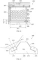
Figure 2 illustrates a top cross-sectional view of the refrigerator appliance according to an embodiment of the present invention; -
Figure 3 illustrates a cross-sectional view of a support beam according to an embodiment of the invention. -
Figures 4A-4C illustrate cross-sectional views of various alternative embodiments of a support beam according to the present invention. -
Figures 5A-5C illustrate perspective views of various alternative embodiments of a support beam according to the present invention. -
Figures 6A-6B illustrate how two support beams are joined together. - Certain terminology is used in the following description for convenience only and is not limiting. The words 'right', `left', 'lower', 'upper', 'front', 'rear', 'upward', 'down' and 'downward' designate directions in the drawings to which reference is made and are with respect to the described component when assembled and mounted. The words 'inner', 'inwardly' and 'outer', 'outwardly' refer to directions toward and away from, respectively, a designated centreline or a geometric centre of an element being described (e.g. central axis), the particular meaning being readily apparent from the context of the description.
- Further, as used herein, the terms 'connected', 'attached', 'coupled', 'mounted' are intended to include direct connections between two members without any other members interposed therebetween, as well as, indirect connections between members in which one or more other members are interposed therebetween. The terminology includes the words specifically mentioned above, derivatives thereof, and words of similar import.
- Further, unless otherwise specified, the use of ordinal adjectives, such as, "first", "second", "third" etc. merely indicate that different instances of like objects are being referred to and are not intended to imply that the objects so described must be in a given sequence, either temporally, spatially, in ranking or in any other manner.
- Like reference numerals are used to depict like features throughout.
- In examples, the refrigerator appliance described herein is a "back bar refrigerator" or "bottle cooler". Back bar refrigerator appliances, also called bottle coolers, are a type of commercial refrigerator that is typically sized to fit within a cavity or recess behind a bar, for example under a worksurface and/or between opposing walls.
-
Figure 2 shows arefrigerator appliance 200 according to an embodiment of the present invention. It comprises a cuboid-shapedcabinet 201 for storing and displaying canned or bottled beverages, said cabinet having aback wall 202, two opposing side walls 203 (only one shown), a top wall, a bottom wall (both not shown), and adoor 207. Although only one end of thecabinet 201 is shown, it will be appreciated that the refrigerator appliance will have a side wall opposite toside wall 203. Thecabinet 201 comprises one ormore storage compartments 205, 205'. Twostorage compartments 205, 205' are shown inFigure 3 , where the divide betweenadjacent storage compartments 205, 205' is indicated at 204. In an embodiment, eachstorage compartment 205, 205' can for example have a width of about 40 cm. Thecabinet 201 can comprise at least one shelf for storing beverages. Eachstorage compartment 205, 205' may comprise one or more shelves. - A
support beam 208 extends vertically between the top wall and the bottom wall 206. In this example thesupport beam 208 is aligned with thedivide 204 betweenadjacent storage compartments 205, 205' in thecabinet 201. Thesupport beam 208 provides a door closure surface against which thedoor 207 is closed. Thedoor 207 may include a sealing element, for example a rubber bead, that is in contact with thesupport beam 208 when the door is closed to form a seal. Thesupport beam 208 may additionally support the top wall (not shown) of thecabinet 201, and/or it may be used to support the or each shelf in the cabinet. For example, thesupport beam 208 may include one or more brackets, or fixing points for brackets, that support a shelf. - It will be understood that the
appliance 200 can comprise one ormore storage compartments 205, 205' within thecabinet 201. In this case, a plurality ofsupport beams 208 can be used, with eachsupport beam 208 being aligned with a divide betweenadjacent storage compartments 205, 205'. Eachstorage compartment 205, 205' may have its own shelves and the shelves may be supported on the support beams 208. A single support beam, such as that shown inFigure 2 , may provide door closure surfaces formultiple doors 207, 207'. - The
appliance 200 may further comprise a technical cabinet located adjacent to or behind thecabinet 201. This technical cabinet may house part of the refrigeration system, particularly those parts that generate heat (i.e., the condenser and compressor), and may additionally house the expansion valve. One or more evaporators of the refrigeration system are typically positioned within the cabinet where the products are stored and act to cool the cabinet. -
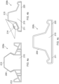
Figure 3 shows the top view cross-section of thesupport beam 208 according to the embodiment of the present invention. Thesupport beam 208 comprises acore 210 and ashell 209. Thecore 210 comprises a foam material, for example, expanded polypropylene. In this embodiment thecore 210 is fully filled with the foam material. Theshell 209 can be made of sheet metal, or a metal alloy, for example, stainless steel. Thesupport beam 208 may be made by folding the sheet metal into the desired profile and then filing it with foam. - The
support beam 208 comprises anexternal surface 211 that is parallel to theback wall 202 of thecabinet 201 and faces thedoor 207, forming a door closure surface. Thesupport beam 208 also includes alight mounting surface 212. In this example, thelight mounting surface 212 is located in arecess 213 that is configured to receive alight source 214. - The
light source 214 can be an LED strip, alternatively, any other type of LED can be used, for example a plurality of LED light bulbs. Alternatively, thelight source 214 may comprise a light guide with a bulb, for example an LED bulb, at one end. Thelight source 214 can have an illumination angle of more than about 90 degrees, for example about 120 degrees, thus providing broad illumination of the contents of thecabinet 201. - The
light source 214 has a primary direction denoted as X-X' that is non-parallel to theback wall 202 of thecabinet 201. In this case, the light is directed into thecabinet 201, thus providing sufficient illumination of the displayed items, and does not interfere with the users as it is directed away from the line of sight of the user. In an alternative embodiment, the primary direction X-X' of thelight source 214 is additionally positioned non-parallel also to theside walls cabinet 201. Such an arrangement means that the primary direction X-X' is angled inwardly into the cabinet, and in particular into eachstorage compartment 205, 205' in the cabinet. - In examples, the primary direction X-X' is at an angle of between about 20 degrees and about 70 degrees from the
back wall 202 of thecabinet 201, for example between about 30 degrees and about 60 degrees, for example about 45 degrees. - It will be further understood that the
light source 214 is mounted inside therecess 213, optionally with the primary direction X-X' being normal to thelight mounting surface 212. - The
support beam 208 further comprises aprojection 215 that, when thesupport beam 208 is mounted on thecabinet 201, extends into thecabinet 201 and is disposed to a side of thelight source 214. Theprojection 215 provides structural strength for thesupport beam 208 and may additionally provide a shelf support or fastening location. As shown, theprojection 215 comprises anangled side 216 that is angled with respect to the back and/or side walls of the cabinet. Theangled side 216 means that theprojection 215 does not block any light from thelight source 214, and provides for greater visibility into thecabinet 201 from the outside. - As explained above, in some embodiments the
cabinet 201 has more than onestorage compartment 205, 205' and more than onedoor 207, 207'. Thesupport beam 208 shown inFigure 3 is positionable at the divide of twoadjacent storage compartments 205, 205' and provides adoor closure surface 211 for twoadjacent doors 207, 207'. In this example, thesupport beam 208 comprises two light sources, namely a firstlight source 214, and a second light source 214'. The second light source 214' is the same as the firstlight source 214 as described above. In this example, thesupport beam 208 comprises acentral projection 215 that is disposed between the first and the secondlight sources 214, 214' and comprises twosides 216 being angled with respect to the back wall of thecabinet 201. Thecentral projection 215 can be trapezoidal shaped. The angled sides 216 improve distribution of light from thelight sources 214, 214' into the cabinet, and improve visibility from the outside of the cabinet. - In some examples, the
support beam 208 may be formed of one half of thesupport beam 208 illustrated inFigure 3 and used at an end of the cabinet, adjacent to a side wall of the cabinet. In such examples, thesupport beam 208 comprises onelight source 214 and provides a door closure surface for a single door. In some examples, therefrigerator appliance 200 includes such support beams 208 at each end of thecabinet 201, adjacent theside walls 203, and onesupport beam 208 as illustrated inFigure 3 provided at thedivide 204 betweenadjacent storage compartments 205, 205'. - It will be understood that the second light source 214' also has a primary direction that is non-parallel to the back and/or side wall of the second cabinet, similarly to the first
light source 214. -
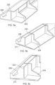
Figures 4A-4C represent various alternative embodiments of the support beam according to the present invention. Thus, inFigure 4A there is provided asupport beam 208a that comprises acentral projection 215, an extrudedprofile shell 209 manufactured from sheet metal, and afoam core 210. It further comprises alight mounting surface 212 with a recess configured to receive a light source 213 (not shown). Thelight source 213 can be attached to the support beam by means of a screw or an adhesive, though other methods known in the art are also contemplated. It can be seen that thefoam core 210 is only partially filled with the foam material with the outmost parts of theshell 209 remaining hollow. -
Figure 4B shows another alternative embodiment of thesupport beam 208b. It also comprises acentral projection 215 disposed between the two light sources 214 (only one is shown). The support beam is produced by thermoforming and comprises a foam-filledcore 210 andthermoplastic shell 209 of uniform wall thickness with rounded corners. Theshell 209 has an opening at thedoor closure surface 211, said opening being covered by ametal strip 220 that is configured to interact with a magnet (not shown) to provide a solid seal. -
Figure 4C is another alternative embodiment of thesupport beam 208c. Thesupport beam 208 is manufactured using rotational moulding. Theshell 209 completely encases the foamedcore 210 and further optionally comprises ametal strip 220 attached to the door contacting surface to interact with the magnet of the door. -
Figures 5A-5c show perspective views of the support beams clamped together to be used between the twoadjacent doors 207, 207' (not shown). Infigure 5A the two support beams 208 (only one is shown for better understanding) are joined together by means of arigid spine 222 having a plurality of attachment surfaces 224. The attachment surfaces 224 allow thesupport beam 208 to grip and set around to thereby resist separation of thesupport beam 208 from thespine 222. The spine is manufactured by injection moulding from any suitable plastic material. As shown infigures 5B and 5C , at least onemetal strip 220 is attached to adoor closure surface 211 to allow the door to remain in closed position. Thespine 222 can also be used to mount other door components, such as product shelves. -
Figure 6A shows the position of the at least onemetal strip 220 attached to thedoor closure surface 211 of the support beam. It is understood that the metal strip can be in the form of a continuous strip that can optionally be a magnet itself. -
Figure 6B shows the way two support beams are clamped together. The clamping means 226 can be used to hold and secure the twosupport beams 208 together. Any fastening means known in the rt can be used as clamping means 226. - It will be appreciated by persons skilled in the art that the above detailed examples have been described by way of example only and not in any limitative sense, and that various alterations and modifications are possible without departing from the scope of the invention as defined by the appended claims. Various modifications to the detailed examples described above are possible.
- Through the description and claims of this specification, the words "comprise" and "contain" and variations of them mean "including but not limited to", and they are not intended to (and do not) exclude other moieties, additives, components, integers or steps. Throughout the description and claims of this specification, the singular encompasses the plural unless the context otherwise requires. In particular, where the indefinite article is used, the specification is to be understood as contemplating plurality as well as singularity, unless the context requires otherwise.
- Features, integers, characteristics, compounds, chemical moieties or groups described in conjunction with a particular aspect, embodiment or example of the invention are to be understood to be applicable to any other aspect, embodiment or example described herein unless incompatible therewith. All of the features disclosed in this specification (including any accompanying claims, abstract and drawings), and/or all of the steps of any method or process so disclosed, may be combined in any combination, except combinations where at least some of such features and/or steps are mutually exclusive. The invention is not restricted to the details of any foregoing embodiments. The invention extends to any novel one, or any novel combination, of the features disclosed in this specification (including any accompanying claims, abstract or drawings), or to any novel one, or any novel combination, of the steps of any method or process so disclosed.
- It will be appreciated by persons skilled in the art that the above embodiment(s) have been described by way of example only and not in any limitative sense, and that various alterations and modifications are possible without departing from the scope of the invention as defined by the appended claims. Various modifications to the detailed designs as described above are possible.
Claims (15)
- A refrigerator appliance comprising:- a cuboid cabinet formed by opposing side walls, a back wall, a top wall and a bottom wall,- a door at a front of the cabinet, and- a support beam extending across the front of the cabinet,wherein the support beam comprises a light source for illuminating the cabinet, the light source having a primary direction that is non-parallel to the back wall of the cabinet.
- The refrigerator appliance of claim 1, wherein said primary direction is non-parallel to the side walls of the cabinet.
- The refrigerator appliance of claim 1 or 2, wherein said primary direction is at an angle of between about 20 degrees and about 70 degrees from the back wall of the cabinet, for example between about 30 degrees and about 60 degrees, for example about 45 degrees.
- The refrigerator appliance of any of claims 1 to 3, wherein the support beam comprises an external surface that is parallel to the back wall of the cabinet, and a light mounting surface against which the light source is mounted such that the primary direction is normal to the light mounting surface, and optionally wherein the support beam comprises a recess for receiving the light source, and wherein the light mounting surface is in the recess.
- The refrigerator appliance of any preceding claim, wherein the support beam comprises a projection extending into the cabinet, the projection being disposed to a side of the light source and comprising an angled side that is non-parallel to the back wall and side walls of the cabinet.
- The refrigerator appliance of any preceding claim, wherein the light source is a first light source for illuminating a first part of the cabinet, wherein the support beam further comprises a second light source for illuminating a second part of the cabinet, the second light source having a primary direction that is non-parallel to the back wall of the cabinet,
optionally wherein the support beam comprises a central projection extending into the cabinet, the central projection being disposed between the first light source and the second light source and comprising angled sides that are non-parallel to the back wall and side walls of the cabinet, and optionally wherein the central projection is trapezoidal. - The refrigerator appliance of any of claims 1 to 6, wherein the support beam comprises a shell and a core, said core comprising a foam material.
- The refrigerator appliance of claim 7, wherein the shell comprises sheet metal.
- The refrigerator appliance of any of claims 1 to 6, wherein the support beam comprises expanded polypropylene.
- The refrigerator appliance of any of claims 1 to 9, wherein the light source comprises an LED strip.
- The refrigerator appliance of any of claims 1 to 10, wherein the light source has an illumination angle of more than about 90 degrees, for example about 120°.
- The refrigerator appliance of any of claims 1 to 11, wherein the refrigerator appliance comprises a plurality of support beams.
- The refrigerator appliance of any preceding claim, wherein the or each support beam extends vertically between the top wall and the bottom wall of the cabinet.
- The refrigerator appliance of any preceding claim, wherein the or each support beam defines a door closure surface against which the door is closed.
- The refrigerator appliance of any of claims 1 to 14, wherein the cabinet comprises at least one shelf and wherein the at least one support beam is configured to support the at least one shelf.
Applications Claiming Priority (1)
| Application Number | Priority Date | Filing Date | Title |
|---|---|---|---|
| GB2311020.8A GB2631957A (en) | 2023-07-19 | 2023-07-19 | A refrigerator appliance |
Publications (1)
| Publication Number | Publication Date |
|---|---|
| EP4494523A1 true EP4494523A1 (en) | 2025-01-22 |
Family
ID=87758588
Family Applications (1)
| Application Number | Title | Priority Date | Filing Date |
|---|---|---|---|
| EP24189527.5A Withdrawn EP4494523A1 (en) | 2023-07-19 | 2024-07-18 | A refrigerator appliance |
Country Status (3)
| Country | Link |
|---|---|
| US (1) | US20250027712A1 (en) |
| EP (1) | EP4494523A1 (en) |
| GB (1) | GB2631957A (en) |
Families Citing this family (1)
| Publication number | Priority date | Publication date | Assignee | Title |
|---|---|---|---|---|
| GB2631957A (en) * | 2023-07-19 | 2025-01-22 | Illinois Tool Works | A refrigerator appliance |
Citations (5)
| Publication number | Priority date | Publication date | Assignee | Title |
|---|---|---|---|---|
| US20060049726A1 (en) * | 2004-09-07 | 2006-03-09 | Sanyo Electric Co., Ltd. | Showcase |
| US20080158858A1 (en) * | 2006-12-29 | 2008-07-03 | Hussmann Corporation | Refrigerated merchandiser with led lighting |
| US20090135587A1 (en) * | 2007-11-22 | 2009-05-28 | Sanyo Electric Co., Ltd. | Showcase |
| US20110304253A1 (en) * | 2010-06-09 | 2011-12-15 | Hill Phoenix, Inc. | Refrigerated case with thermal door frame |
| US20140119015A1 (en) * | 2011-02-11 | 2014-05-01 | Brian K. Morgan | Energy-saving networked illumination system |
Family Cites Families (24)
| Publication number | Priority date | Publication date | Assignee | Title |
|---|---|---|---|---|
| US4818043A (en) * | 1987-05-13 | 1989-04-04 | Margaret P. Borgen | Product display and marketing device |
| US5895111A (en) * | 1992-04-08 | 1999-04-20 | Anthony's Manufacturing Company, Inc. | Display case with lens lighting system |
| US5471372A (en) * | 1993-12-06 | 1995-11-28 | Ardco, Inc. | Lighting system for commercial refrigerator doors |
| US6121545A (en) * | 1997-07-11 | 2000-09-19 | Parker-Hannifin Corporation | Low closure force EMI shielding spacer gasket |
| EP1761146B1 (en) * | 2004-05-26 | 2016-06-29 | GE Lighting Solutions, LLC | Led lighting systems for product display cases |
| ES2557159T3 (en) * | 2004-12-23 | 2016-01-22 | Nualight Limited | Display case lighting |
| US20080186696A1 (en) * | 2007-02-03 | 2008-08-07 | Awai George K | Light emitting diode waveguide assemblies for illuminating refrigerated areas |
| US7824067B2 (en) * | 2007-03-21 | 2010-11-02 | Thomas & Betts International, Inc. | Emergency light fixture having an efficient reflector assembly |
| WO2009052172A2 (en) * | 2007-10-15 | 2009-04-23 | Hussmann Corporation | Led lighting assembly with leds having different viewing angles |
| US8070305B2 (en) * | 2008-07-25 | 2011-12-06 | Hussmann Corporation | Mullion assembly for a refrigerated merchandiser |
| US20100097780A1 (en) * | 2008-10-21 | 2010-04-22 | John Bryan Beatenbough | Refrigerated led illumination system |
| GB2468036B (en) * | 2009-02-20 | 2013-03-13 | Hussmann Corp | High efficacy LED light assembly for a merchandiser |
| US8579462B2 (en) * | 2011-01-05 | 2013-11-12 | Itc Incorporated | Lighting assembly |
| AT511899B1 (en) * | 2011-08-24 | 2018-05-15 | Aht Cooling Systems Gmbh | COOLING DEVICE FOR COOLED, IN PARTICULAR DEEP-COOLED GOODS |
| EP2998670B1 (en) * | 2013-04-23 | 2020-08-05 | LG Electronics Inc. | A camera system for installation inside a refrigerator and a refrigerator comprising said camera system |
| US11125412B2 (en) * | 2014-12-01 | 2021-09-21 | Current Lighting Solutions, Llc | Lighting device with efficient light-spreading lens system |
| US9687087B1 (en) * | 2016-06-16 | 2017-06-27 | Anthony, Inc. | Display case door assembly with vacuum panel and lighting features |
| CN108489170A (en) * | 2018-03-07 | 2018-09-04 | 青岛海尔特种电冰柜有限公司 | A kind of horizontal refrigerator with lighting device |
| CN109578941B (en) * | 2018-12-25 | 2024-07-09 | 赛尔富电子有限公司 | Refrigerator-freezer illumination lens system |
| WO2020194682A1 (en) * | 2019-03-28 | 2020-10-01 | 三菱電機株式会社 | Refrigerator |
| CN110822314B (en) * | 2019-11-01 | 2025-04-15 | 赛尔富电子有限公司 | A strip light used in a display cabinet |
| KR102196859B1 (en) * | 2019-11-20 | 2020-12-30 | 아성산업 주식회사 | Glass door |
| GB2631959A (en) * | 2023-07-19 | 2025-01-22 | Illinois Tool Works | Support beam for a refrigerator |
| GB2631957A (en) * | 2023-07-19 | 2025-01-22 | Illinois Tool Works | A refrigerator appliance |
-
2023
- 2023-07-19 GB GB2311020.8A patent/GB2631957A/en active Pending
-
2024
- 2024-07-18 EP EP24189527.5A patent/EP4494523A1/en not_active Withdrawn
- 2024-07-19 US US18/777,653 patent/US20250027712A1/en active Pending
Patent Citations (5)
| Publication number | Priority date | Publication date | Assignee | Title |
|---|---|---|---|---|
| US20060049726A1 (en) * | 2004-09-07 | 2006-03-09 | Sanyo Electric Co., Ltd. | Showcase |
| US20080158858A1 (en) * | 2006-12-29 | 2008-07-03 | Hussmann Corporation | Refrigerated merchandiser with led lighting |
| US20090135587A1 (en) * | 2007-11-22 | 2009-05-28 | Sanyo Electric Co., Ltd. | Showcase |
| US20110304253A1 (en) * | 2010-06-09 | 2011-12-15 | Hill Phoenix, Inc. | Refrigerated case with thermal door frame |
| US20140119015A1 (en) * | 2011-02-11 | 2014-05-01 | Brian K. Morgan | Energy-saving networked illumination system |
Also Published As
| Publication number | Publication date |
|---|---|
| US20250027712A1 (en) | 2025-01-23 |
| GB202311020D0 (en) | 2023-08-30 |
| GB2631957A (en) | 2025-01-22 |
Similar Documents
| Publication | Publication Date | Title |
|---|---|---|
| EP2818814B1 (en) | Refrigerator | |
| US20250027712A1 (en) | Refrigerator appliance | |
| US20250334324A1 (en) | Appliance mounting system | |
| US11221175B1 (en) | Liner hanger | |
| EP4495518A1 (en) | A refrigerator appliance | |
| GB2219851A (en) | Domestic refrigerator | |
| EP3908794B1 (en) | Refrigerator | |
| EP4494527A1 (en) | A back bar refrigerator appliance | |
| US11555647B2 (en) | Rear bracket for shelf assembly | |
| GB2631961A (en) | A back bar refrigerator appliance | |
| JP3920092B2 (en) | Showcase | |
| CN116772510B (en) | Storage partition plate for refrigerator and refrigerator | |
| EP4242563A1 (en) | A refrigerator comprising a container | |
| JP2001082862A (en) | Refrigerating showcase | |
| JPH01210792A (en) | Refrigerator | |
| JPH06147747A (en) | Storage box for refrigerator | |
| KR200217350Y1 (en) | Door guard height adjustment structure of the refrigerator | |
| KR200313612Y1 (en) | Shelf of refrigerator | |
| KR20040029852A (en) | Body assembly using adiabatic panel for refrigerator/show-case and manufacturing method thereof | |
| RU11671U1 (en) | REFRIGERATION SHOWCASE | |
| JP3675882B2 (en) | Cooling storage | |
| JP2014137186A (en) | Refrigerator | |
| JP2000245597A (en) | Showcase | |
| KR19990053005A (en) | Cabinet of refrigerator | |
| KR20000011266U (en) | Supporting device for angled lathe |
Legal Events
| Date | Code | Title | Description |
|---|---|---|---|
| PUAI | Public reference made under article 153(3) epc to a published international application that has entered the european phase |
Free format text: ORIGINAL CODE: 0009012 |
|
| STAA | Information on the status of an ep patent application or granted ep patent |
Free format text: STATUS: THE APPLICATION HAS BEEN PUBLISHED |
|
| AK | Designated contracting states |
Kind code of ref document: A1 Designated state(s): AL AT BE BG CH CY CZ DE DK EE ES FI FR GB GR HR HU IE IS IT LI LT LU LV MC ME MK MT NL NO PL PT RO RS SE SI SK SM TR |
|
| STAA | Information on the status of an ep patent application or granted ep patent |
Free format text: STATUS: THE APPLICATION IS DEEMED TO BE WITHDRAWN |
|
| 18D | Application deemed to be withdrawn |
Effective date: 20250723 |