EP4494497A1 - Aerosol-generating system and aerosol-generating article - Google Patents
Aerosol-generating system and aerosol-generating article Download PDFInfo
- Publication number
- EP4494497A1 EP4494497A1 EP23857494.1A EP23857494A EP4494497A1 EP 4494497 A1 EP4494497 A1 EP 4494497A1 EP 23857494 A EP23857494 A EP 23857494A EP 4494497 A1 EP4494497 A1 EP 4494497A1
- Authority
- EP
- European Patent Office
- Prior art keywords
- aerosol generating
- medium
- aerosol
- accommodation portion
- wall
- Prior art date
- Legal status (The legal status is an assumption and is not a legal conclusion. Google has not performed a legal analysis and makes no representation as to the accuracy of the status listed.)
- Pending
Links
Images





Classifications
-
- A—HUMAN NECESSITIES
- A24—TOBACCO; CIGARS; CIGARETTES; SIMULATED SMOKING DEVICES; SMOKERS' REQUISITES
- A24F—SMOKERS' REQUISITES; MATCH BOXES; SIMULATED SMOKING DEVICES
- A24F40/00—Electrically operated smoking devices; Component parts thereof; Manufacture thereof; Maintenance or testing thereof; Charging means specially adapted therefor
- A24F40/40—Constructional details, e.g. connection of cartridges and battery parts
-
- A—HUMAN NECESSITIES
- A24—TOBACCO; CIGARS; CIGARETTES; SIMULATED SMOKING DEVICES; SMOKERS' REQUISITES
- A24B—MANUFACTURE OR PREPARATION OF TOBACCO FOR SMOKING OR CHEWING; TOBACCO; SNUFF
- A24B13/00—Tobacco for pipes, for cigars, e.g. cigar inserts, or for cigarettes; Chewing tobacco; Snuff
-
- A—HUMAN NECESSITIES
- A24—TOBACCO; CIGARS; CIGARETTES; SIMULATED SMOKING DEVICES; SMOKERS' REQUISITES
- A24B—MANUFACTURE OR PREPARATION OF TOBACCO FOR SMOKING OR CHEWING; TOBACCO; SNUFF
- A24B15/00—Chemical features or treatment of tobacco; Tobacco substitutes, e.g. in liquid form
- A24B15/10—Chemical features of tobacco products or tobacco substitutes
- A24B15/12—Chemical features of tobacco products or tobacco substitutes of reconstituted tobacco
-
- A—HUMAN NECESSITIES
- A24—TOBACCO; CIGARS; CIGARETTES; SIMULATED SMOKING DEVICES; SMOKERS' REQUISITES
- A24B—MANUFACTURE OR PREPARATION OF TOBACCO FOR SMOKING OR CHEWING; TOBACCO; SNUFF
- A24B15/00—Chemical features or treatment of tobacco; Tobacco substitutes, e.g. in liquid form
- A24B15/10—Chemical features of tobacco products or tobacco substitutes
- A24B15/16—Chemical features of tobacco products or tobacco substitutes of tobacco substitutes
-
- A—HUMAN NECESSITIES
- A24—TOBACCO; CIGARS; CIGARETTES; SIMULATED SMOKING DEVICES; SMOKERS' REQUISITES
- A24D—CIGARS; CIGARETTES; TOBACCO SMOKE FILTERS; MOUTHPIECES OF CIGARS OR CIGARETTES; MANUFACTURE OF TOBACCO SMOKE FILTERS OR MOUTHPIECES
- A24D1/00—Cigars; Cigarettes
- A24D1/20—Cigarettes specially adapted for simulated smoking devices
-
- A—HUMAN NECESSITIES
- A24—TOBACCO; CIGARS; CIGARETTES; SIMULATED SMOKING DEVICES; SMOKERS' REQUISITES
- A24F—SMOKERS' REQUISITES; MATCH BOXES; SIMULATED SMOKING DEVICES
- A24F40/00—Electrically operated smoking devices; Component parts thereof; Manufacture thereof; Maintenance or testing thereof; Charging means specially adapted therefor
- A24F40/40—Constructional details, e.g. connection of cartridges and battery parts
- A24F40/42—Cartridges or containers for inhalable precursors
-
- A—HUMAN NECESSITIES
- A24—TOBACCO; CIGARS; CIGARETTES; SIMULATED SMOKING DEVICES; SMOKERS' REQUISITES
- A24F—SMOKERS' REQUISITES; MATCH BOXES; SIMULATED SMOKING DEVICES
- A24F40/00—Electrically operated smoking devices; Component parts thereof; Manufacture thereof; Maintenance or testing thereof; Charging means specially adapted therefor
- A24F40/40—Constructional details, e.g. connection of cartridges and battery parts
- A24F40/46—Shape or structure of electric heating means
- A24F40/465—Shape or structure of electric heating means specially adapted for induction heating
-
- A—HUMAN NECESSITIES
- A24—TOBACCO; CIGARS; CIGARETTES; SIMULATED SMOKING DEVICES; SMOKERS' REQUISITES
- A24F—SMOKERS' REQUISITES; MATCH BOXES; SIMULATED SMOKING DEVICES
- A24F40/00—Electrically operated smoking devices; Component parts thereof; Manufacture thereof; Maintenance or testing thereof; Charging means specially adapted therefor
- A24F40/40—Constructional details, e.g. connection of cartridges and battery parts
- A24F40/48—Fluid transfer means, e.g. pumps
- A24F40/485—Valves; Apertures
-
- A—HUMAN NECESSITIES
- A24—TOBACCO; CIGARS; CIGARETTES; SIMULATED SMOKING DEVICES; SMOKERS' REQUISITES
- A24F—SMOKERS' REQUISITES; MATCH BOXES; SIMULATED SMOKING DEVICES
- A24F47/00—Smokers' requisites not otherwise provided for
-
- H—ELECTRICITY
- H05—ELECTRIC TECHNIQUES NOT OTHERWISE PROVIDED FOR
- H05B—ELECTRIC HEATING; ELECTRIC LIGHT SOURCES NOT OTHERWISE PROVIDED FOR; CIRCUIT ARRANGEMENTS FOR ELECTRIC LIGHT SOURCES, IN GENERAL
- H05B6/00—Heating by electric, magnetic or electromagnetic fields
- H05B6/02—Induction heating
- H05B6/10—Induction heating apparatus, other than furnaces, for specific applications
- H05B6/105—Induction heating apparatus, other than furnaces, for specific applications using a susceptor
-
- H—ELECTRICITY
- H05—ELECTRIC TECHNIQUES NOT OTHERWISE PROVIDED FOR
- H05B—ELECTRIC HEATING; ELECTRIC LIGHT SOURCES NOT OTHERWISE PROVIDED FOR; CIRCUIT ARRANGEMENTS FOR ELECTRIC LIGHT SOURCES, IN GENERAL
- H05B6/00—Heating by electric, magnetic or electromagnetic fields
- H05B6/02—Induction heating
- H05B6/10—Induction heating apparatus, other than furnaces, for specific applications
- H05B6/105—Induction heating apparatus, other than furnaces, for specific applications using a susceptor
- H05B6/108—Induction heating apparatus, other than furnaces, for specific applications using a susceptor for heating a fluid
-
- H—ELECTRICITY
- H05—ELECTRIC TECHNIQUES NOT OTHERWISE PROVIDED FOR
- H05B—ELECTRIC HEATING; ELECTRIC LIGHT SOURCES NOT OTHERWISE PROVIDED FOR; CIRCUIT ARRANGEMENTS FOR ELECTRIC LIGHT SOURCES, IN GENERAL
- H05B6/00—Heating by electric, magnetic or electromagnetic fields
- H05B6/02—Induction heating
- H05B6/36—Coil arrangements
-
- A—HUMAN NECESSITIES
- A24—TOBACCO; CIGARS; CIGARETTES; SIMULATED SMOKING DEVICES; SMOKERS' REQUISITES
- A24B—MANUFACTURE OR PREPARATION OF TOBACCO FOR SMOKING OR CHEWING; TOBACCO; SNUFF
- A24B15/00—Chemical features or treatment of tobacco; Tobacco substitutes, e.g. in liquid form
- A24B15/10—Chemical features of tobacco products or tobacco substitutes
- A24B15/16—Chemical features of tobacco products or tobacco substitutes of tobacco substitutes
- A24B15/167—Chemical features of tobacco products or tobacco substitutes of tobacco substitutes in liquid or vaporisable form, e.g. liquid compositions for electronic cigarettes
-
- A—HUMAN NECESSITIES
- A24—TOBACCO; CIGARS; CIGARETTES; SIMULATED SMOKING DEVICES; SMOKERS' REQUISITES
- A24F—SMOKERS' REQUISITES; MATCH BOXES; SIMULATED SMOKING DEVICES
- A24F40/00—Electrically operated smoking devices; Component parts thereof; Manufacture thereof; Maintenance or testing thereof; Charging means specially adapted therefor
- A24F40/20—Devices using solid inhalable precursors
Definitions
- the following embodiments relate to an aerosol generating system and an aerosol generating article.
- Korean Patent Application Publication No. 10-2017-0132823 discloses a non-combustion-type flavor inhaler, a flavor inhalation component source unit, and an atomizing unit.
- An object according to an embodiment is to provide an aerosol generating system for cooling an aerosol generated inside a device by introduced external air to have a large amount of atomization.
- Another object according to an embodiment is to provide an aerosol generating article that may be used as a medium for both chewing tobacco and heated tobacco.
- An aerosol generating system includes an aerosol generating device, and an aerosol generating article accommodated in the medium accommodation portion.
- the aerosol generating device includes a housing including a first housing end and a second housing end on a side opposite to the first housing end, an external air inflow unit detachably coupled to the first housing end of the housing, a medium accommodation portion disposed in the housing and including a first wall and a second wall facing the first wall, a heating unit disposed outside the first wall and the second wall of the medium accommodation portion and configured to heat the aerosol generating article accommodated in the medium accommodation portion, and an airflow path tube fluidly connecting the medium accommodation portion and the second housing end of the housing, and the external air inflow unit includes a perforation that causes an external fluid of the aerosol generating device to flow into the inside of the aerosol generating device.
- the aerosol generating article may include a medium portion, and an outer cover portion that covers outer surfaces of the medium accommodation portion, and may include a first surface that contacts with an inner surface of the first wall and a second surface that contacts with an inner surface of the second wall when the aerosol generating article is accommodated in the medium accommodation portion.
- the heating unit may further include a susceptor surrounding at least two surfaces of the medium accommodation portion, and an induction coil that induces a variable magnetic field to the susceptor.
- the heating unit may be configured to contact with an outer surface of the first wall and an outer surface of the second wall of the medium accommodation portion to directly heat the aerosol generating article accommodated in the medium accommodation portion.
- a width between the first wall and the second wall of the medium accommodation portion of the aerosol generating device may be smaller than or equal to a width between the first surface and the second surface of the aerosol generating article.
- the external air inflow unit may further include a mouthpiece unit
- the aerosol generating device includes a first airflow path fluidly connecting the mouthpiece unit and the medium accommodation portion, and a second airflow path fluidly connecting the first airflow path and the outside of the aerosol generating device.
- the external air inflow unit may reduce a temperature of an aerosol as a fluid introduced through the perforation moves along the second airflow path when a user inhales through the mouthpiece unit.
- An aerosol generating article includes a first surface, a second surface formed on a side opposite to the first surface, and one or more side surfaces perpendicular to the first surface and the second surface, a medium portion including a first medium surface, a second medium surface formed on a side opposite to the first medium surface, and one or more medium side surfaces perpendicular to the first medium surface and the second medium surface, and an outer cover portion covering the first medium surface, the second medium surface, and the medium side surfaces of the medium portion and formed of a porous material.
- the aerosol generating article may be selectively transferred by a method in which the aerosol generating article is inserted into the medium accommodation portion of the aerosol generating device of claim 1 to be transferred through an aerosol generated by heating or a method in which the aerosol generating article is inserted into user's mouth to be directly transferred.
- the first surface and the second surface of the aerosol generating article may have the same shape and area.
- each area of the first surface and the second surface may be larger than an area of the side surface.
- the aerosol generating system may cool an aerosol generated inside a device by introduced external air to obtain a sufficient atomization amount.
- the aerosol generating article according to an embodiment may be used as a medium for chewing tobacco or heated tobacco.
- an expression such as "at least one of” that precedes listed components modifies not each of the listed components but all the listed components.
- the expression “at least one of a, b, or c” should be construed as including a, b, c, a and b, a and c, b and c, or a, b, and c.
- the term "aerosol generating article” may refer to an article that accommodates a medium, in which an aerosol passes through the article and the medium is transferred.
- a representative example of the aerosol generating article may be a cigarette.
- the scope of the disclosure is not limited thereto.
- upstream or “upstream direction” may refer to a direction away from an oral region of a user (smoker), and the term “downstream” or “downstream direction” may refer to a direction approaching the oral region of the user.
- upstream and downstream may be used to describe relative positions of components of an aerosol generating article.
- the term "puff” refers to inhalation by a user, and the inhalation refers to a situation in which a user draws in an aerosol into his or her oral cavity, nasal cavity, or lungs through the mouth or nose.
- an aerosol generating device may be a device that generates an aerosol by electrically heating an aerosol generating article accommodated in an inner space.
- the aerosol generating device may include a heater.
- the heater may be an electrically resistive heater.
- the heater may include an electrically conductive track, and the heater may be heated as a current flows through the electrically conductive track.
- the heater may include a tubular heating element, a plate-shaped heating element, a needle-shaped heating element, or a rod-shaped heating element, and may heat the inside or outside of the aerosol generating article according to the shape of a heating element.
- the aerosol generating article may include a tobacco rod and a filter rod.
- the tobacco rod may be formed as a sheet or a strand, or may be formed of tobacco leaves finely cut from a tobacco sheet.
- the tobacco rod may be enveloped by a thermally conductive material.
- the thermally conductive material may be metal foil such as aluminum foil.
- embodiments are not limited thereto.
- the filter rod may be a cellulose acetate filter.
- the filter rod may include at least one segment.
- the filter rod may include a first segment that cools an aerosol and a second segment that filters a predetermined ingredient contained in the aerosol.
- the aerosol generating device may be a device that generates an aerosol using a cartridge containing an aerosol generating material.
- the aerosol generating device may include a cartridge containing the aerosol generating material and a main body supporting the cartridge.
- the cartridge may be detachably coupled to the main body.
- the cartridge may be integrally formed or assembled with the main body, and may be secured to the main body so as not to be detached by a user.
- the cartridge may be mounted on the main body while the aerosol generating material is accommodated therein.
- the aerosol generating material may be injected into the cartridge while the cartridge is coupled to the main body.
- the cartridge may hold the aerosol generating material in any one of various states, such as a liquid state, a solid state, a gaseous state, and a gel state.
- the aerosol generating material may include a liquid composition.
- the liquid composition may be a liquid including a tobacco-containing material having a volatile tobacco flavor component, or may be a liquid including a non-tobacco material.
- the cartridge may be operated by an electrical signal or a wireless signal transmitted from the main body to perform the function of generating an aerosol by converting a phase of the aerosol generating material inside the cartridge to a gaseous phase.
- the aerosol may refer to a gas in which vaporized particles generated from the aerosol generating material are mixed with air.
- the aerosol generating device may generate an aerosol by heating the liquid composition, and the generated aerosol may pass through the cigarette and be delivered to the user. That is, the aerosol generated from the liquid composition may travel along an airflow path of the aerosol generating device, and the airflow path may be configured to allow the aerosol to pass through the cigarette and be delivered to the user.
- the aerosol generating device may be a device that generates an aerosol from the aerosol generating material using an ultrasonic vibration manner.
- the ultrasonic vibration manner may refer to a manner of generating an aerosol by atomizing the aerosol generating material with ultrasonic vibration generated by a vibrator.
- the aerosol generating device may include a vibrator, and may generate vibration at short intervals through the vibrator to atomize the aerosol generating material.
- the vibration generated by the vibrator may be ultrasonic vibration, and a frequency band of the ultrasonic vibration may be from about 100 kilohertz (kHz) to about 3.5 megahertz (MHz).
- kHz kilohertz
- MHz megahertz
- the aerosol generating device may further include a wick that absorbs the aerosol generating material.
- the wick may be disposed to surround at least one area of the vibrator or may be disposed to contact at least one area of the vibrator.
- the vibrator may generate heat and/or ultrasonic vibration, and the heat and/or ultrasonic vibration generated by the vibrator may be transmitted to the aerosol generating material absorbed in the wick.
- the aerosol generating material absorbed in the wick may be converted into a gas phase by the heat and/or ultrasonic vibration transmitted from the vibrator, and consequently, an aerosol may be generated.
- the viscosity of the aerosol generating material absorbed in the wick may be lowered by the heat generated by the vibrator, and the aerosol generating material whose viscosity is lowered may change to fine particles by the ultrasonic vibration generated by the vibrator, so that an aerosol may be generated.
- embodiments are not limited thereto.
- the aerosol generating device may be a device that generates an aerosol by heating the aerosol generating article accommodated therein in an induction heating manner.
- the aerosol generating device may include a susceptor and a coil.
- the coil may apply a magnetic field to the susceptor.
- a magnetic field may be formed inside the coil.
- the susceptor may be a magnetic body that generates heat by an external magnetic field. As the susceptor is positioned inside the coil and generates heat with the magnetic field applied, the aerosol generating article may be heated. Also, optionally, the susceptor may be positioned in the aerosol generating article.
- the aerosol generating device may further include a cradle.
- the aerosol generating device and the separate cradle may form a system together.
- the cradle may be used to charge a battery of the aerosol generating device.
- a heater may be heated when the cradle and the aerosol generating device are coupled to each other.
- FIG. 1 is a block diagram of an aerosol generating device 100 according to an embodiment.
- the aerosol generating device 100 may include a controller 110, a sensing unit 120, an output unit 130, a battery 140, a heater 150, a user input unit 160, a memory 170, and a communication unit 180.
- a controller 110 may include a controller 110, a sensing unit 120, an output unit 130, a battery 140, a heater 150, a user input unit 160, a memory 170, and a communication unit 180.
- an internal structure of the aerosol generating device 100 is not limited to what is shown in FIG. 1 . It is to be understood by one of ordinary skill in the art to which the disclosure pertains that some of the components shown in FIG. 1 may be omitted or new components may be added according to the design of the aerosol generating device 100.
- the sensing unit 120 may sense a state of the aerosol generating device 100 or a state of an environment around the aerosol generating device 100, and transmit sensing information obtained through the sensing to the controller 110. Based on the sensing information, the controller 110 may control the aerosol generating device 100 to control operations of the heater 150, restrict smoking, determine whether an aerosol generating article (e.g., an aerosol generating article, a cartridge, etc.) is inserted, display a notification, and perform other functions.
- an aerosol generating article e.g., an aerosol generating article, a cartridge, etc.
- the sensing unit 120 may include at least one of a temperature sensor 122, an insertion detection sensor 124, or a puff sensor 126. However, embodiments are not limited thereto.
- the temperature sensor 122 may sense a temperature at which the heater 150 (or an aerosol generating material) is heated.
- the aerosol generating device 100 may include a separate temperature sensor for sensing the temperature of the heater 150, or the heater 150 itself may also function as a temperature sensor.
- the temperature sensor 122 may be arranged around the battery 140 to monitor a temperature of the battery 140.
- the insertion detection sensor 124 may sense whether the aerosol generating article is inserted and/or removed.
- the insertion detection sensor 124 may include, for example, at least one of a film sensor, a pressure sensor, a light sensor, a resistive sensor, a capacitive sensor, an inductive sensor, or an infrared sensor, which may sense a signal change by the insertion and/or removal of the aerosol generating article.
- the puff sensor 126 may sense a puff from a user based on various physical changes in an airflow path or airflow channel. For example, the puff sensor 126 may sense the puff from the user based on one of a temperature change, a flow change, a voltage change, and a pressure change.
- the sensing unit 120 may further include at least one of a temperature/humidity sensor, an atmospheric pressure sensor, a magnetic sensor, an acceleration sensor, a gyroscope sensor, a position sensor (e.g., a global positioning system (GPS)), a proximity sensor, or a red, green, blue (RGB) sensor (e.g., an illuminance sensor), in addition to the sensors 122 to 126 described above.
- a temperature/humidity sensor e.g., an atmospheric pressure sensor, a magnetic sensor, an acceleration sensor, a gyroscope sensor, a position sensor (e.g., a global positioning system (GPS)), a proximity sensor, or a red, green, blue (RGB) sensor (e.g., an illuminance sensor), in addition to the sensors 122 to 126 described above.
- GPS global positioning system
- RGB red, green, blue
- the output unit 130 may output information about the state of the aerosol generating device 100 and provide the information to the user.
- the output unit 130 may include at least one of a display 132, a haptic portion 134, or a sound outputter 136. However, embodiments are not limited thereto.
- the display 132 and a touchpad are provided in a layered structure to form a touchscreen, the display 132 may be used as an input device in addition to an output device.
- the display 132 may visually provide information about the aerosol generating device 100 to the user.
- the information about the aerosol generating device 100 may include, for example, a charging/discharging state of the battery 140 of the aerosol generating device 100, a preheating state of the heater 150, an insertion/removal state of the aerosol generating article, a limited usage state (e.g., an abnormal article detected) of the aerosol generating device 100, or the like, and the display 132 may externally output the information.
- the display 132 may be, for example, a liquid-crystal display panel (LCD), an organic light-emitting display panel (OLED), or the like.
- the display 132 may also be in the form of a light-emitting diode (LED) device.
- LED light-emitting diode
- the haptic portion 134 may provide information about the aerosol generating device 100 to the user in a haptic way by converting an electrical signal into a mechanical stimulus or an electrical stimulus.
- the haptic portion 134 may include, for example, a motor, a piezoelectric element, or an electrical stimulation device.
- the sound outputter 136 may provide information about the aerosol generating device 100 to the user in an auditory way.
- the sound outputter 136 may convert an electrical signal into a sound signal and externally output the sound signal.
- the battery 140 may supply power to be used to operate the aerosol generating device 100.
- the battery 140 may supply power to heat the heater 150.
- the battery 140 may supply power required for operations of the other components (e.g., the sensing unit 120, the output unit 130, the user input unit 160, the memory 170, and the communication unit 180) included in the aerosol generating device 100.
- the battery 140 may be a rechargeable battery or a disposable battery.
- the battery 140 may be, for example, a lithium polymer (LiPoly) battery. However, embodiments are not limited thereto.
- the heater 150 may receive power from the battery 140 to heat the aerosol generating material.
- the aerosol generating device 100 may further include a power conversion circuit (e.g., a direct current (DC)-to-DC (DC/DC) converter) that converts power of the battery 140 and supplies the power to the heater 150.
- a power conversion circuit e.g., a direct current (DC)-to-DC (DC/DC) converter
- DC/AC DC-to-alternating current
- the controller 110, the sensing unit 120, the output unit 130, the user input unit 160, the memory 170, and the communication unit 180 may receive power from the battery 140 to perform functions.
- the aerosol generating device 100 may further include a power conversion circuit, for example, a low dropout (LDO) circuit or a voltage regulator circuit, which converts power of the battery 140 and supplies the power to respective components.
- LDO low dropout
- the heater 150 may be formed of a predetermined electrically resistive material that is suitable.
- the electrically resistive material may be a metal or a metal alloy including, for example, titanium, zirconium, tantalum, platinum, nickel, cobalt, chromium, hafnium, niobium, molybdenum, tungsten, tin, gallium, manganese, iron, copper, stainless steel, nichrome, or the like.
- the heater 150 may be implemented as a metal heating wire, a metal heating plate on which an electrically conductive track is arranged, a ceramic heating element, or the like.
- embodiments are not limited thereto.
- the heater 150 may be an induction heater.
- the heater 150 may include a susceptor that heats the aerosol generating material by generating heat through a magnetic field applied by a coil.
- the heater 150 may include a plurality of heaters.
- the heater 150 may include a first heater for heating the aerosol generating article and a second heater for heating a liquid.
- the user input unit 160 may receive information input from the user or may output information to the user.
- the user input unit 160 may include a key pad, a dome switch, a touchpad (e.g., a contact capacitive type, a pressure resistive film type, an infrared sensing type, a surface ultrasonic conduction type, an integral tension measurement type, a piezo effect method, etc.), a jog wheel, a jog switch, or the like.
- a connection interface such as a universal serial bus (USB) interface, and may be connected to another external device through the connection interface such as a USB interface to transmit and receive information or to charge the battery 140.
- USB universal serial bus
- the memory 170 which is hardware for storing various pieces of data processed in the aerosol generating device 100, may store data processed by the controller 110 and data to be processed by the controller 110.
- the memory 170 may include at least one type of storage medium of flash memory-type memory, hard disk-type memory, multimedia card micro-type memory, card-type memory (e.g., secure digital (SD) or extreme digital (XD) memory), random access memory (RAM), static RAM (SRAM), read-only memory (ROM), electrically erasable programmable ROM (EEPROM), programmable ROM (PROM), magnetic memory, a magnetic disk, or an optical disk.
- the memory 170 may store an operating time of the aerosol generating device 100, a maximum number of puffs, a current number of puffs, at least one temperature profile, data associated with a smoking pattern of the user, or the like.
- the communication unit 180 may include at least one component for communicating with another electronic device.
- the communication unit 180 may include a short-range wireless communication unit 182 and a wireless communication unit 184.
- the short-range wireless communication unit 182 may include a Bluetooth communication unit, a Bluetooth low energy (BLE) communication unit, a near field communication unit, a wireless local area network (WLAN) (wireless fidelity (Wi-Fi)) communication unit, a ZigBee communication unit, an infrared data association (IrDA) communication unit, a Wi-Fi direct (WFD) communication unit, an ultra-wideband (UWB) communication unit, and an Ant+ communication unit.
- BLE Bluetooth low energy
- WLAN wireless local area network
- Wi-Fi wireless fidelity
- ZigBee ZigBee communication unit
- IrDA infrared data association
- WFD Wi-Fi direct
- UWB ultra-wideband
- the wireless communication unit 184 may include, for example, a cellular network communication unit, an Internet communication unit, a computer network (e.g., a LAN or wide-area network (WAN) communication unit, or the like. However, embodiments are not limited thereto.
- the wireless communication unit 184 may use subscriber information (e.g., international mobile subscriber identity (IMSI)) to identify and authenticate the aerosol generating device 100 in a communication network.
- IMSI international mobile subscriber identity
- the controller 110 may control the overall operation of the aerosol generating device 100.
- the controller 110 may include at least one processor.
- the processor may be implemented as an array of a plurality of logic gates, or may be implemented as a combination of a general-purpose microprocessor and a memory in which a program executable by the microprocessor is stored.
- a general-purpose microprocessor and a memory in which a program executable by the microprocessor is stored.
- the controller 110 may control the temperature of the heater 150 by controlling supply of power from the battery 140 to the heater 150.
- the controller 110 may control the supply of power by controlling switching of a switching element between the battery 140 and the heater 150.
- a direct heating circuit may control the supply of power to the heater 150 according to a control command from the controller 110.
- the controller 110 may analyze a sensing result obtained by the sensing of the sensing unit 120 and control processes to be performed thereafter. For example, the controller 110 may control power to be supplied to the heater 150 to start or end an operation of the heater 150 based on the sensing result obtained by the sensing unit 120. In another example, the controller 110 may control an amount of power to be supplied to the heater 150 and a time for which the power is to be supplied, such that the heater 150 may be heated up to a predetermined temperature or maintained at a desired temperature, based on the sensing result obtained by the sensing unit 120.
- the controller 110 may control the output unit 130 based on the sensing result obtained by the sensing unit 120. For example, when the number of puffs counted through the puff sensor 126 reaches a preset number, the controller 110 may inform the user that the aerosol generating device 100 is to be ended soon, through at least one of the display 132, the haptic portion 134, or the sound outputter 136.
- the controller 110 may control a power supply time and/or a power supply amount for the heater 150 according to a state of the aerosol generating article sensed by the sensing unit 120. For example, when the aerosol generating article is in an over-humidified state, the controller 110 may control the power supply time for an inductive coil to increase a preheating time, compared to a case where the aerosol generating article is in a general state.
- An embodiment may be implemented in the form of a recording medium including instructions executable by a computer, such as a program module executable by the computer.
- a computer-readable medium may be any available medium that may be accessed by a computer and includes a volatile medium, a non-volatile medium, a removable medium, and a non-removable medium.
- the computer-readable medium may include both a computer storage medium and a communication medium.
- the computer storage medium includes all of a volatile medium, a non-volatile medium, a removable medium, and a non-removable medium implemented by any method or technology for storage of information such as computer-readable instructions, data structures, program modules or other data.
- the communication medium typically includes computer-readable instructions, data structures, other data in modulated data signals such as program modules, or other transmission mechanisms, and includes any information transfer medium.
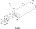
- FIG. 2A is a perspective view of an aerosol generating system 10 according to an embodiment.
- FIG. 2B is a cross-sectional view of the aerosol generating system 10 according to an embodiment.
- FIG. 2C is an exploded perspective view of the aerosol generating system 10 according to an embodiment.
- the aerosol generating system 10 may include an aerosol generating device 200 and an aerosol generating article 400.
- the aerosol generating article 400 may be disposed inside the aerosol generating device 200.
- the aerosol generating article 400 may be heated inside the aerosol generating device 200 to form an aerosol.
- the configuration of the aerosol generating device 200 and the aerosol generating article 400 included in the aerosol generating system 10 will be described in detail.
- the aerosol generating device 200 may include a housing 210, an external air inflow unit 220, a medium accommodation portion 230, a heating unit 240, an airflow path tube 250, a mouthpiece unit 260, a display unit 270, a battery 280, and a controller 290.
- the housing 210 may include a first housing end 210a and a second housing end 210b.
- the first housing end 210a of the housing 210 may include a surface to be coupled to the external air inflow unit 220.
- the second housing end 210b of the housing 210 may be formed on a side opposite to the first housing end 210a.
- the external air inflow unit 220 may be coupled to the first housing end 210a of the housing 210.
- the external air inflow unit 220 may be detachably coupled to the housing 210.
- the external air inflow unit 220 may include a first inflow end 220a that comes into contact with the first housing end 210a of the housing 210, and a second inflow end 220b formed on a side opposite to the first inflow end 220a.
- the external air inflow unit 220 may further include side inflow surfaces 220c formed between the first inflow end 220a and the second inflow end 220b.
- the external air inflow unit 220 may include a perforation 222.
- the perforation 222 may be formed in at least one of the side inflow surfaces 220c of the external air inflow unit 220.
- an external fluid of the aerosol generating device 200 may flow into the aerosol generating device 200 through the perforation 222.
- the medium accommodation portion 230 may have a space in which the aerosol generating article 400 is accommodated.
- the medium accommodation portion 230 may be disposed inside the housing 210.
- the medium accommodation portion 230 may include a first wall 230a and a second wall 230b facing the first wall 230a.
- the medium accommodation portion 230 may accommodate the aerosol generating article 400.
- the aerosol generating article 400 accommodated inside the medium accommodation portion 230 may be accommodated to fit tight inside the medium accommodation portion 230.
- the heating unit 240 may heat the aerosol generating article 400 accommodated inside the medium accommodation portion 230.
- the aerosol generating article 400 heated by the heating unit 240 may form an aerosol.
- the heating unit 240 may be disposed in contact with outer surfaces of the first wall 230a and the second wall 230b of the medium accommodation portion 230.
- the heating unit 240 may be in contact with the outer surfaces of the first wall 230a and the second wall 230b of the medium accommodation portion 230 and directly heat the aerosol generating article accommodated in the medium accommodation portion 230 using conduction heat.
- the heating unit 240 may be disposed in contact with the outer surfaces of the first wall 230a and the second wall 230b to minimize a loss of heat generated in the heating unit 240.
- the heating unit 240 may generate heat by methods such as conductive heating, inductive heating, convective heating, microwave heating, laser heating, optical heating, dielectric heating, etc.
- the heat generation method of the heating unit 240 is not limited to the above examples and may further include a heating method that is conceivable by those skilled in the art.
- the airflow path tube 250 may fluidly connect the second end 210b of the housing 210 and the medium accommodation portion 230.
- inhalation resistance that a user experiences when using the aerosol generating system 10 may be adjusted according to a length and width of the airflow path tube 250. As the length and width of the airflow path tube 250 are longer and narrower, the inhalation resistance may increase. As the length and width of the airflow path tube 250 are shorter and wider, the inhalation resistance may decrease. In an embodiment, the airflow path tube 250 may have a width narrower than a width Wd of the medium accommodation portion 230.
- the mouthpiece unit 260 may be disposed in contact with the second end 220b of the external air inflow unit 220.
- the mouthpiece unit 260 is a part that the user's mouth directly touches, and the user may inhale an aerosol generated in the aerosol generating system 10 through the mouthpiece unit 260.
- the aerosol generating device 200 may include at least two airflow paths. Referring to FIG. 2B , the aerosol generating device 200 may include a first airflow path f1 and a second airflow path f2.
- the first airflow path f1 may fluidly connect at least the medium accommodation portion 230, the external air inflow unit 220, and the mouthpiece unit 260.
- An aerosol generated by heating the medium accommodation portion 230 may flow to the mouthpiece unit 260 through the external air inflow unit 220.
- the first airflow path f1 may further fluidly connect the airflow path tube 250.
- a fluid flowing in through a through hole (not shown) of the second end 210b of the housing 210 may sequentially pass through the aerosol generating article 400 accommodated in the medium accommodation portion 230 to the external air inflow unit 220 and the mouthpiece unit 260.
- a flow of the fluid through the first airflow path f1 may correspond to a main flow delivering the aerosol of the aerosol generating system 10 to the user's mouth.
- the second airflow path f2 may include a flow of an external fluid introduced through the perforation 222 of the external air inflow unit 220.
- a temperature of the fluid flowing through the second airflow path f2 may be lower than a temperature of the fluid flowing through the first airflow path f1.
- the fluid flowing through the second airflow path f2 may include an external fluid around the aerosol generating system 10.
- the second airflow path f2 may be perpendicular to the first airflow path f2.
- the second airflow path f2 may form an oblique angle with the first airflow path f2.
- the external fluid flowing through the second airflow path f2 may be mixed with the fluid flowing through the first airflow path f1 inside the external air inflow unit 220.
- the fluid flowing through the second airflow path f2 may cool the fluid flowing through the first airflow path f1 to cause a phase change in the fluid.
- condensation may occur and the amount of aerosol may increase.
- sublimation which is conversion of a substance from a gaseous state to a solid state
- the amount of aerosol flowing through the inside of the mouthpiece unit 260 may further increase.
- a sensory evaluation result for the amount of aerosol that is, a level of an atomization amount, generated when the user inhales the aerosol using the aerosol generating system 10 is as shown in Table 1.
- evaluators expressed an average satisfaction level of about 4 points out of 7 points.
- the satisfaction of the evaluators with the aerosol generating system 10 according to an embodiment was about 4.7 points, showing a significant difference.
- the sample size for the sensory evaluation is a total of 13 people.
- the display unit 270 may visually provide information about the aerosol generating device 200 to the user.
- the information about the aerosol generating device 200 may include, for example, a charging/discharging state of the battery 280 of the aerosol generating device 200, a preheating state of the heating unit 240, an insertion/removal state of the aerosol generating article 400, a limited usage state (e.g., an abnormal article detected) of the aerosol generating device 200, or the like, and the display unit 270 may externally output the information.
- the display unit 270 may be, for example, an LCD, an OLED, or the like.
- the display unit 270 may also be in the form of an LED device.
- the battery 280 may supply power to be used to operate the aerosol generating device 200.
- the battery 280 may supply power to heat the heating unit 240 and supply power required to operate the controller 290 (e.g., the controller 110 of FIG. 1 ).
- the battery 280 may supply power required to operate the display unit 270, a sensor (e.g., the sensing unit 120 of FIG. 1 ), a motor, or the like installed in the aerosol generating device 200.
- the controller 290 may control the overall operation of the aerosol generating device 200.
- the controller 290 may control power supplied to the heating unit 240 from the battery 280.
- the controller 290 may also control respective operations of other components included in the aerosol generating device 200, in addition to the battery 280 and the heating unit 240.
- the controller 290 may verify a state of each of the components of the aerosol generating device 200 to determine whether the aerosol generating device 200 is in an operable state.
- the controller 290 may include a printed circuit board (PCB) 292 and a PCB frame 294.
- the PCB 292 may be seated inside the PCB frame 294 (see FIG. 2C ).
- an aerosol generating device 300 (e.g., the aerosol generating device 200) may include all of the components according to the embodiment described above.
- the common components to those in the aerosol generating device 200 according to the embodiment described above have been described in detail with reference to FIGS. 2A to 2C , and therefore, the description thereof will be omitted hereinafter.
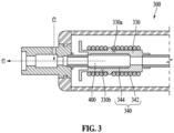
- FIG. 3 is a cross-sectional view of an aerosol generating system (e.g., the aerosol generating system 10 of FIG. 2 ) according to an embodiment.
- an aerosol generating system e.g., the aerosol generating system 10 of FIG. 2
- the aerosol generating device 300 may include a medium accommodation portion 330 and the heating unit 340.
- the medium accommodation portion 330 may have a space in which the aerosol generating article 400 is accommodated.
- the medium accommodation portion 330 may be disposed inside a housing (e.g., the housing 210 of FIG. 2A and/or FIG. 2C ).
- the medium accommodation portion 330 may include a first wall 330a and a second wall 330b facing the first wall 330a.
- the medium accommodation portion 330 may accommodate the aerosol generating article 400.
- the aerosol generating article 400 accommodated inside the medium accommodation portion 330 may be accommodated to fit tight inside the medium accommodation portion 330.
- the heating unit 340 may heat the aerosol generating article 400 accommodated inside the medium accommodation portion 330.
- the aerosol generating article 400 heated by the heating unit 340 may form an aerosol.
- the heating unit 340 may be disposed in contact with outer surfaces of the first wall 330a and the second wall 330b of the medium accommodation portion 330.
- the heating unit 340 may be disposed with a gap to be spaced apart from the outer surfaces of the first wall 330a and the second wall 330b of the medium accommodation portion 330.
- the heating unit 340 may include an induction coil 342 and a susceptor 344. The heating unit 340 may heat the aerosol generating article 400 using an induction heating method.
- the heating unit 340 may heat the aerosol generating article 400 using the susceptor 344, which is heated by generating heat through a variable magnetic field applied by the induction coil 342.
- the induction coil 342 may be wound along outer walls of the medium accommodation portion 330, in which the aerosol generating article 400 is accommodated, to induce a variable magnetic field.
- the susceptor 344 may be disposed in contact with the outer surface of the first wall 330a and the outer surface of the second wall 230b of the medium accommodation portion 330. In an embodiment, the susceptor 344 may be disposed in contact with the outer surfaces of the first wall 330a and the second wall 330b to minimize a loss of heat generated in the heating unit 340.
- the susceptor 344 may be disposed on an outer surface of the aerosol generating article 400.
- the heating unit 340 of the aerosol generating device 300 may not include the susceptor 344.
- FIG. 4A is a perspective view of the aerosol generating article 400 according to an embodiment.
- FIG. 4B is a cross-sectional view of the aerosol generating article 400 according to an embodiment.
- the aerosol generating article 400 may include a medium portion 410 and an outer cover portion 420. In an embodiment, the aerosol generating article 400 may include a first surface 400a and a second surface 400b formed on a side opposite to the first surface 400a. In an embodiment, the aerosol generating article 400 may be accommodated in a medium accommodation portion (e.g., the medium accommodation portion 230 of FIGS. 2A to 2C and/or the medium accommodation portion 330 of FIG. 3 ) of an aerosol generating device (e.g., the aerosol generating device 200 of FIGS. 2A to 2C and/or the aerosol generating device 300 of FIG.
- a medium accommodation portion e.g., the medium accommodation portion 230 of FIGS. 2A to 2C and/or the medium accommodation portion 330 of FIG. 3
- an aerosol generating device e.g., the aerosol generating device 200 of FIGS. 2A to 2C and/or the aerosol generating device 300 of FIG.
- a first wall e.g., the first wall 230a of FIGS. 2A to 2C or the first wall 330a of FIG. 3
- the second surface 400b contacts with an inner surface of a second wall (e.g., the second wall 230b of FIGS. 2A to 2C or the second wall 330b of FIG. 3 ).
- a heat loss may be minimized as both surfaces 400a and 400b of the aerosol generating article 400 are disposed in contact with the inner surfaces of the first wall (230a; 330a) and the second wall (230b; 330b) of the medium accommodation portion (230; 330).
- a width e.g., the width Wd of FIG.
- the aerosol generating article 400 may be more firmly accommodated inside the medium accommodation portion (230; 330) by a difference between the width Wd of the medium accommodation portion (230; 330) and the width of the aerosol generating article 400.
- the medium portion 410 may include a first medium surface 410a, a second medium surface 410b formed on a side opposite to the first medium surface 410a, and one or more medium side surfaces 410c perpendicular to the first medium surface 410a and the second medium surface 410b.
- the outer cover portion 420 may cover at least one of the first medium surface 410a, the second medium surface 410b, and the medium side surfaces 410c of the medium portion 410.
- the outer cover portion 420 may be formed of a porous material.
- the first surface 400a and the second surface 400b of the aerosol generating article 400 may have the same shape and area. In an embodiment, the first surface 400a and the second surface 400b of the aerosol generating article 400 may have a triangular shape. In an embodiment, the first surface 400a and the second surface 400b of the aerosol generating article 400 may have a rectangular shape. In an embodiment, the first surface 400a and the second surface 400b of the aerosol generating article 400 may have a pentagonal shape. In an embodiment, the first surface 400a and the second surface 400b of the aerosol generating article 400 may have a hexagonal shape. In an embodiment, the first surface 400a and the second surface 400b of the aerosol generating article 400 may have a circular shape.
- each area of the first surface 400a and/or the second surface 400b of the aerosol generating article 400 may be larger than an area of the side surface 400c. That is, the aerosol generating article 400 may have a wide and flat shape.
Landscapes
- Physics & Mathematics (AREA)
- Electromagnetism (AREA)
- Chemical & Material Sciences (AREA)
- Chemical Kinetics & Catalysis (AREA)
- General Chemical & Material Sciences (AREA)
- Resistance Heating (AREA)
- Containers And Packaging Bodies Having A Special Means To Remove Contents (AREA)
Abstract
Description
- The following embodiments relate to an aerosol generating system and an aerosol generating article.
- Recently, demands for alternative articles to overcome disadvantages of general cigarettes have increased. For example, there is an increasing demand for a device (e.g., a cigarette-type electronic cigarette) that generates an aerosol by electrically heating a cigarette stick. Accordingly, research on an electrically heated aerosol generating device and a cigarette stick (or an aerosol generating article) applied thereto is being actively conducted. For example,
Korean Patent Application Publication No. 10-2017-0132823 - An object according to an embodiment is to provide an aerosol generating system for cooling an aerosol generated inside a device by introduced external air to have a large amount of atomization.
- Another object according to an embodiment is to provide an aerosol generating article that may be used as a medium for both chewing tobacco and heated tobacco.
- An aerosol generating system according to various embodiments includes an aerosol generating device, and an aerosol generating article accommodated in the medium accommodation portion. The aerosol generating device includes a housing including a first housing end and a second housing end on a side opposite to the first housing end, an external air inflow unit detachably coupled to the first housing end of the housing, a medium accommodation portion disposed in the housing and including a first wall and a second wall facing the first wall, a heating unit disposed outside the first wall and the second wall of the medium accommodation portion and configured to heat the aerosol generating article accommodated in the medium accommodation portion, and an airflow path tube fluidly connecting the medium accommodation portion and the second housing end of the housing, and the external air inflow unit includes a perforation that causes an external fluid of the aerosol generating device to flow into the inside of the aerosol generating device.
- In an embodiment, the aerosol generating article may include a medium portion, and an outer cover portion that covers outer surfaces of the medium accommodation portion, and may include a first surface that contacts with an inner surface of the first wall and a second surface that contacts with an inner surface of the second wall when the aerosol generating article is accommodated in the medium accommodation portion.
- In an embodiment, the heating unit may further include a susceptor surrounding at least two surfaces of the medium accommodation portion, and an induction coil that induces a variable magnetic field to the susceptor.
- In an embodiment, the heating unit may be configured to contact with an outer surface of the first wall and an outer surface of the second wall of the medium accommodation portion to directly heat the aerosol generating article accommodated in the medium accommodation portion.
- In an embodiment, a width between the first wall and the second wall of the medium accommodation portion of the aerosol generating device may be smaller than or equal to a width between the first surface and the second surface of the aerosol generating article.
- In an embodiment, the external air inflow unit may further include a mouthpiece unit, and the aerosol generating device includes a first airflow path fluidly connecting the mouthpiece unit and the medium accommodation portion, and a second airflow path fluidly connecting the first airflow path and the outside of the aerosol generating device.
- In an embodiment, the external air inflow unit may reduce a temperature of an aerosol as a fluid introduced through the perforation moves along the second airflow path when a user inhales through the mouthpiece unit.
- An aerosol generating article according to various embodiments includes a first surface, a second surface formed on a side opposite to the first surface, and one or more side surfaces perpendicular to the first surface and the second surface, a medium portion including a first medium surface, a second medium surface formed on a side opposite to the first medium surface, and one or more medium side surfaces perpendicular to the first medium surface and the second medium surface, and an outer cover portion covering the first medium surface, the second medium surface, and the medium side surfaces of the medium portion and formed of a porous material. The aerosol generating article may be selectively transferred by a method in which the aerosol generating article is inserted into the medium accommodation portion of the aerosol generating device of claim 1 to be transferred through an aerosol generated by heating or a method in which the aerosol generating article is inserted into user's mouth to be directly transferred.
- In an embodiment, the first surface and the second surface of the aerosol generating article may have the same shape and area.
- In an embodiment, each area of the first surface and the second surface may be larger than an area of the side surface.
- The aerosol generating system according to an embodiment may cool an aerosol generated inside a device by introduced external air to obtain a sufficient atomization amount.
- The aerosol generating article according to an embodiment may be used as a medium for chewing tobacco or heated tobacco.
- The effects of the aerosol generating system and the aerosol generating article according to an embodiment are not limited to the above-mentioned effects, and other unmentioned effects may be clearly understood from the following description by one of ordinary skill in the art.
-
-
FIG. 1 is a block diagram of an aerosol generating device according to an embodiment. -
FIG. 2A is a perspective view of an aerosol generating system according to an embodiment. -
FIG. 2B is a cross-sectional view of an aerosol generating system according to an embodiment. -
FIG. 2C is an exploded perspective view of an aerosol generating system according to an embodiment. -
FIG. 3 is a cross-sectional view of an aerosol generating system according to an embodiment. -
FIG. 4A is a perspective view of an aerosol generating article according to an embodiment. -
FIG. 4B is a cross-sectional view of an aerosol generating article according to an embodiment. - The terms used in the embodiments are selected from among common terms that are currently widely used, in consideration of their function in the disclosure. However, the terms may become different according to an intention of one of ordinary skill in the art, a precedent, or the advent of new technology. Also, in particular cases, the terms are discretionally selected by the applicant of the disclosure, and the meaning of those terms will be described in detail in the corresponding part of the detailed description. Therefore, the terms used in the disclosure are not merely designations of the terms, but the terms are defined based on the meaning of the terms and content throughout the disclosure.
- It will be understood that when a certain part "includes" a certain component, the part does not exclude another component but may further include another component, unless the context clearly dictates otherwise. Also, terms such as "unit," "module," etc., as used in the specification may refer to a part for processing at least one function or operation and which may be implemented as hardware, software, or a combination of hardware and software.
- As used herein, an expression such as "at least one of" that precedes listed components modifies not each of the listed components but all the listed components. For example, the expression "at least one of a, b, or c" should be construed as including a, b, c, a and b, a and c, b and c, or a, b, and c.
- In the following embodiments, the term "aerosol generating article" may refer to an article that accommodates a medium, in which an aerosol passes through the article and the medium is transferred. A representative example of the aerosol generating article may be a cigarette. However, the scope of the disclosure is not limited thereto.
- In the following embodiments, the term "upstream" or "upstream direction" may refer to a direction away from an oral region of a user (smoker), and the term "downstream" or "downstream direction" may refer to a direction approaching the oral region of the user. The terms "upstream" and "downstream" may be used to describe relative positions of components of an aerosol generating article.
- In the following embodiments, the term "puff" refers to inhalation by a user, and the inhalation refers to a situation in which a user draws in an aerosol into his or her oral cavity, nasal cavity, or lungs through the mouth or nose.
- In an embodiment, an aerosol generating device may be a device that generates an aerosol by electrically heating an aerosol generating article accommodated in an inner space.
- The aerosol generating device may include a heater. In an embodiment, the heater may be an electrically resistive heater. For example, the heater may include an electrically conductive track, and the heater may be heated as a current flows through the electrically conductive track.
- The heater may include a tubular heating element, a plate-shaped heating element, a needle-shaped heating element, or a rod-shaped heating element, and may heat the inside or outside of the aerosol generating article according to the shape of a heating element.
- The aerosol generating article may include a tobacco rod and a filter rod. The tobacco rod may be formed as a sheet or a strand, or may be formed of tobacco leaves finely cut from a tobacco sheet. In addition, the tobacco rod may be enveloped by a thermally conductive material. For example, the thermally conductive material may be metal foil such as aluminum foil. However, embodiments are not limited thereto.
- The filter rod may be a cellulose acetate filter. The filter rod may include at least one segment. For example, the filter rod may include a first segment that cools an aerosol and a second segment that filters a predetermined ingredient contained in the aerosol.
- In another embodiment, the aerosol generating device may be a device that generates an aerosol using a cartridge containing an aerosol generating material.
- The aerosol generating device may include a cartridge containing the aerosol generating material and a main body supporting the cartridge. The cartridge may be detachably coupled to the main body. However, embodiments are not limited thereto. The cartridge may be integrally formed or assembled with the main body, and may be secured to the main body so as not to be detached by a user. The cartridge may be mounted on the main body while the aerosol generating material is accommodated therein. However, embodiments are not limited thereto. The aerosol generating material may be injected into the cartridge while the cartridge is coupled to the main body.
- The cartridge may hold the aerosol generating material in any one of various states, such as a liquid state, a solid state, a gaseous state, and a gel state. The aerosol generating material may include a liquid composition. For example, the liquid composition may be a liquid including a tobacco-containing material having a volatile tobacco flavor component, or may be a liquid including a non-tobacco material.
- The cartridge may be operated by an electrical signal or a wireless signal transmitted from the main body to perform the function of generating an aerosol by converting a phase of the aerosol generating material inside the cartridge to a gaseous phase. The aerosol may refer to a gas in which vaporized particles generated from the aerosol generating material are mixed with air.
- In another embodiment, the aerosol generating device may generate an aerosol by heating the liquid composition, and the generated aerosol may pass through the cigarette and be delivered to the user. That is, the aerosol generated from the liquid composition may travel along an airflow path of the aerosol generating device, and the airflow path may be configured to allow the aerosol to pass through the cigarette and be delivered to the user.
- In another embodiment, the aerosol generating device may be a device that generates an aerosol from the aerosol generating material using an ultrasonic vibration manner. In this case, the ultrasonic vibration manner may refer to a manner of generating an aerosol by atomizing the aerosol generating material with ultrasonic vibration generated by a vibrator.
- The aerosol generating device may include a vibrator, and may generate vibration at short intervals through the vibrator to atomize the aerosol generating material. The vibration generated by the vibrator may be ultrasonic vibration, and a frequency band of the ultrasonic vibration may be from about 100 kilohertz (kHz) to about 3.5 megahertz (MHz). However, embodiments are not limited thereto.
- The aerosol generating device may further include a wick that absorbs the aerosol generating material. For example, the wick may be disposed to surround at least one area of the vibrator or may be disposed to contact at least one area of the vibrator.
- As a voltage (e.g., an alternating voltage) is applied to the vibrator, the vibrator may generate heat and/or ultrasonic vibration, and the heat and/or ultrasonic vibration generated by the vibrator may be transmitted to the aerosol generating material absorbed in the wick. The aerosol generating material absorbed in the wick may be converted into a gas phase by the heat and/or ultrasonic vibration transmitted from the vibrator, and consequently, an aerosol may be generated.
- For example, the viscosity of the aerosol generating material absorbed in the wick may be lowered by the heat generated by the vibrator, and the aerosol generating material whose viscosity is lowered may change to fine particles by the ultrasonic vibration generated by the vibrator, so that an aerosol may be generated. However, embodiments are not limited thereto.
- In another embodiment, the aerosol generating device may be a device that generates an aerosol by heating the aerosol generating article accommodated therein in an induction heating manner.
- The aerosol generating device may include a susceptor and a coil. In an embodiment, the coil may apply a magnetic field to the susceptor. As the aerosol generating device supplies power to the coil, a magnetic field may be formed inside the coil. In an embodiment, the susceptor may be a magnetic body that generates heat by an external magnetic field. As the susceptor is positioned inside the coil and generates heat with the magnetic field applied, the aerosol generating article may be heated. Also, optionally, the susceptor may be positioned in the aerosol generating article.
- In another embodiment, the aerosol generating device may further include a cradle.
- The aerosol generating device and the separate cradle may form a system together. For example, the cradle may be used to charge a battery of the aerosol generating device. Alternatively, a heater may be heated when the cradle and the aerosol generating device are coupled to each other.
- Hereinafter, embodiments of the disclosure will be described in detail with reference to the accompanying drawings such that one of ordinary skill in the art may easily practice the disclosure. The disclosure may be practiced in forms that are implementable in the aerosol generating devices according to various embodiments described above or may be embodied and practiced in many different forms and is not limited to the embodiments described herein.
- Hereinafter, embodiments of the disclosure will be described in detail with reference to the drawings.
-
FIG. 1 is a block diagram of anaerosol generating device 100 according to an embodiment. - The
aerosol generating device 100 may include acontroller 110, asensing unit 120, anoutput unit 130, abattery 140, aheater 150, a user input unit 160, amemory 170, and acommunication unit 180. However, an internal structure of theaerosol generating device 100 is not limited to what is shown inFIG. 1 . It is to be understood by one of ordinary skill in the art to which the disclosure pertains that some of the components shown inFIG. 1 may be omitted or new components may be added according to the design of theaerosol generating device 100. - The
sensing unit 120 may sense a state of theaerosol generating device 100 or a state of an environment around theaerosol generating device 100, and transmit sensing information obtained through the sensing to thecontroller 110. Based on the sensing information, thecontroller 110 may control theaerosol generating device 100 to control operations of theheater 150, restrict smoking, determine whether an aerosol generating article (e.g., an aerosol generating article, a cartridge, etc.) is inserted, display a notification, and perform other functions. - The
sensing unit 120 may include at least one of atemperature sensor 122, aninsertion detection sensor 124, or apuff sensor 126. However, embodiments are not limited thereto. - The
temperature sensor 122 may sense a temperature at which the heater 150 (or an aerosol generating material) is heated. Theaerosol generating device 100 may include a separate temperature sensor for sensing the temperature of theheater 150, or theheater 150 itself may also function as a temperature sensor. Alternatively, thetemperature sensor 122 may be arranged around thebattery 140 to monitor a temperature of thebattery 140. - The
insertion detection sensor 124 may sense whether the aerosol generating article is inserted and/or removed. Theinsertion detection sensor 124 may include, for example, at least one of a film sensor, a pressure sensor, a light sensor, a resistive sensor, a capacitive sensor, an inductive sensor, or an infrared sensor, which may sense a signal change by the insertion and/or removal of the aerosol generating article. - The
puff sensor 126 may sense a puff from a user based on various physical changes in an airflow path or airflow channel. For example, thepuff sensor 126 may sense the puff from the user based on one of a temperature change, a flow change, a voltage change, and a pressure change. - The
sensing unit 120 may further include at least one of a temperature/humidity sensor, an atmospheric pressure sensor, a magnetic sensor, an acceleration sensor, a gyroscope sensor, a position sensor (e.g., a global positioning system (GPS)), a proximity sensor, or a red, green, blue (RGB) sensor (e.g., an illuminance sensor), in addition to thesensors 122 to 126 described above. A function of each sensor may be intuitively inferable from its name by one of ordinary skill in the art, and thus, a more detailed description thereof will be omitted here. - The
output unit 130 may output information about the state of theaerosol generating device 100 and provide the information to the user. Theoutput unit 130 may include at least one of adisplay 132, ahaptic portion 134, or asound outputter 136. However, embodiments are not limited thereto. When thedisplay 132 and a touchpad are provided in a layered structure to form a touchscreen, thedisplay 132 may be used as an input device in addition to an output device. - The
display 132 may visually provide information about theaerosol generating device 100 to the user. The information about theaerosol generating device 100 may include, for example, a charging/discharging state of thebattery 140 of theaerosol generating device 100, a preheating state of theheater 150, an insertion/removal state of the aerosol generating article, a limited usage state (e.g., an abnormal article detected) of theaerosol generating device 100, or the like, and thedisplay 132 may externally output the information. Thedisplay 132 may be, for example, a liquid-crystal display panel (LCD), an organic light-emitting display panel (OLED), or the like. Thedisplay 132 may also be in the form of a light-emitting diode (LED) device. - The
haptic portion 134 may provide information about theaerosol generating device 100 to the user in a haptic way by converting an electrical signal into a mechanical stimulus or an electrical stimulus. Thehaptic portion 134 may include, for example, a motor, a piezoelectric element, or an electrical stimulation device. - The
sound outputter 136 may provide information about theaerosol generating device 100 to the user in an auditory way. For example, thesound outputter 136 may convert an electrical signal into a sound signal and externally output the sound signal. - The
battery 140 may supply power to be used to operate theaerosol generating device 100. Thebattery 140 may supply power to heat theheater 150. In addition, thebattery 140 may supply power required for operations of the other components (e.g., thesensing unit 120, theoutput unit 130, the user input unit 160, thememory 170, and the communication unit 180) included in theaerosol generating device 100. Thebattery 140 may be a rechargeable battery or a disposable battery. Thebattery 140 may be, for example, a lithium polymer (LiPoly) battery. However, embodiments are not limited thereto. - The
heater 150 may receive power from thebattery 140 to heat the aerosol generating material. Although not shown inFIG. 1 , theaerosol generating device 100 may further include a power conversion circuit (e.g., a direct current (DC)-to-DC (DC/DC) converter) that converts power of thebattery 140 and supplies the power to theheater 150. In addition, when theaerosol generating device 100 generates an aerosol by induction heating, theaerosol generating device 100 may further include a DC-to-alternating current (AC) (DC/AC) converter that converts DC power of thebattery 140 into AC power. - The
controller 110, thesensing unit 120, theoutput unit 130, the user input unit 160, thememory 170, and thecommunication unit 180 may receive power from thebattery 140 to perform functions. Although not shown inFIG. 1 , theaerosol generating device 100 may further include a power conversion circuit, for example, a low dropout (LDO) circuit or a voltage regulator circuit, which converts power of thebattery 140 and supplies the power to respective components. - In an embodiment, the
heater 150 may be formed of a predetermined electrically resistive material that is suitable. The electrically resistive material may be a metal or a metal alloy including, for example, titanium, zirconium, tantalum, platinum, nickel, cobalt, chromium, hafnium, niobium, molybdenum, tungsten, tin, gallium, manganese, iron, copper, stainless steel, nichrome, or the like. However, embodiments are not limited thereto. In addition, theheater 150 may be implemented as a metal heating wire, a metal heating plate on which an electrically conductive track is arranged, a ceramic heating element, or the like. However, embodiments are not limited thereto. - In another embodiment, the
heater 150 may be an induction heater. For example, theheater 150 may include a susceptor that heats the aerosol generating material by generating heat through a magnetic field applied by a coil. - In an embodiment, the
heater 150 may include a plurality of heaters. For example, theheater 150 may include a first heater for heating the aerosol generating article and a second heater for heating a liquid. - The user input unit 160 may receive information input from the user or may output information to the user. For example, the user input unit 160 may include a key pad, a dome switch, a touchpad (e.g., a contact capacitive type, a pressure resistive film type, an infrared sensing type, a surface ultrasonic conduction type, an integral tension measurement type, a piezo effect method, etc.), a jog wheel, a jog switch, or the like. However, embodiments are not limited thereto. In addition, although not shown in
FIG. 1 , theaerosol generating device 100 may further include a connection interface such as a universal serial bus (USB) interface, and may be connected to another external device through the connection interface such as a USB interface to transmit and receive information or to charge thebattery 140. - The
memory 170, which is hardware for storing various pieces of data processed in theaerosol generating device 100, may store data processed by thecontroller 110 and data to be processed by thecontroller 110. Thememory 170 may include at least one type of storage medium of flash memory-type memory, hard disk-type memory, multimedia card micro-type memory, card-type memory (e.g., secure digital (SD) or extreme digital (XD) memory), random access memory (RAM), static RAM (SRAM), read-only memory (ROM), electrically erasable programmable ROM (EEPROM), programmable ROM (PROM), magnetic memory, a magnetic disk, or an optical disk. Thememory 170 may store an operating time of theaerosol generating device 100, a maximum number of puffs, a current number of puffs, at least one temperature profile, data associated with a smoking pattern of the user, or the like. - The
communication unit 180 may include at least one component for communicating with another electronic device. For example, thecommunication unit 180 may include a short-rangewireless communication unit 182 and awireless communication unit 184. - The short-range
wireless communication unit 182 may include a Bluetooth communication unit, a Bluetooth low energy (BLE) communication unit, a near field communication unit, a wireless local area network (WLAN) (wireless fidelity (Wi-Fi)) communication unit, a ZigBee communication unit, an infrared data association (IrDA) communication unit, a Wi-Fi direct (WFD) communication unit, an ultra-wideband (UWB) communication unit, and an Ant+ communication unit. However, embodiments are not limited thereto. - The
wireless communication unit 184 may include, for example, a cellular network communication unit, an Internet communication unit, a computer network (e.g., a LAN or wide-area network (WAN) communication unit, or the like. However, embodiments are not limited thereto. Thewireless communication unit 184 may use subscriber information (e.g., international mobile subscriber identity (IMSI)) to identify and authenticate theaerosol generating device 100 in a communication network. - The
controller 110 may control the overall operation of theaerosol generating device 100. In an embodiment, thecontroller 110 may include at least one processor. The processor may be implemented as an array of a plurality of logic gates, or may be implemented as a combination of a general-purpose microprocessor and a memory in which a program executable by the microprocessor is stored. In addition, it is to be understood by one of ordinary skill in the art to which the present disclosure pertains that it may be implemented in other types of hardware. - The
controller 110 may control the temperature of theheater 150 by controlling supply of power from thebattery 140 to theheater 150. For example, thecontroller 110 may control the supply of power by controlling switching of a switching element between thebattery 140 and theheater 150. In another example, a direct heating circuit may control the supply of power to theheater 150 according to a control command from thecontroller 110. - The
controller 110 may analyze a sensing result obtained by the sensing of thesensing unit 120 and control processes to be performed thereafter. For example, thecontroller 110 may control power to be supplied to theheater 150 to start or end an operation of theheater 150 based on the sensing result obtained by thesensing unit 120. In another example, thecontroller 110 may control an amount of power to be supplied to theheater 150 and a time for which the power is to be supplied, such that theheater 150 may be heated up to a predetermined temperature or maintained at a desired temperature, based on the sensing result obtained by thesensing unit 120. - The
controller 110 may control theoutput unit 130 based on the sensing result obtained by thesensing unit 120. For example, when the number of puffs counted through thepuff sensor 126 reaches a preset number, thecontroller 110 may inform the user that theaerosol generating device 100 is to be ended soon, through at least one of thedisplay 132, thehaptic portion 134, or thesound outputter 136. - In an embodiment, the
controller 110 may control a power supply time and/or a power supply amount for theheater 150 according to a state of the aerosol generating article sensed by thesensing unit 120. For example, when the aerosol generating article is in an over-humidified state, thecontroller 110 may control the power supply time for an inductive coil to increase a preheating time, compared to a case where the aerosol generating article is in a general state. - An embodiment may be implemented in the form of a recording medium including instructions executable by a computer, such as a program module executable by the computer. A computer-readable medium may be any available medium that may be accessed by a computer and includes a volatile medium, a non-volatile medium, a removable medium, and a non-removable medium. In addition, the computer-readable medium may include both a computer storage medium and a communication medium. The computer storage medium includes all of a volatile medium, a non-volatile medium, a removable medium, and a non-removable medium implemented by any method or technology for storage of information such as computer-readable instructions, data structures, program modules or other data. The communication medium typically includes computer-readable instructions, data structures, other data in modulated data signals such as program modules, or other transmission mechanisms, and includes any information transfer medium.
-
FIG. 2A is a perspective view of anaerosol generating system 10 according to an embodiment.FIG. 2B is a cross-sectional view of theaerosol generating system 10 according to an embodiment.FIG. 2C is an exploded perspective view of theaerosol generating system 10 according to an embodiment. - Referring to
FIG. 2A , theaerosol generating system 10 may include anaerosol generating device 200 and anaerosol generating article 400. In an embodiment, theaerosol generating article 400 may be disposed inside theaerosol generating device 200. In an embodiment, theaerosol generating article 400 may be heated inside theaerosol generating device 200 to form an aerosol. Hereinafter, the configuration of theaerosol generating device 200 and theaerosol generating article 400 included in theaerosol generating system 10 will be described in detail. - Referring to
FIGS. 2A to 2C , theaerosol generating device 200 may include ahousing 210, an externalair inflow unit 220, amedium accommodation portion 230, aheating unit 240, anairflow path tube 250, amouthpiece unit 260, adisplay unit 270, abattery 280, and a controller 290. - The
housing 210 according to an embodiment may include afirst housing end 210a and asecond housing end 210b. Thefirst housing end 210a of thehousing 210 may include a surface to be coupled to the externalair inflow unit 220. Thesecond housing end 210b of thehousing 210 may be formed on a side opposite to thefirst housing end 210a. - The external
air inflow unit 220 according to an embodiment may be coupled to thefirst housing end 210a of thehousing 210. In an embodiment, the externalair inflow unit 220 may be detachably coupled to thehousing 210. In an embodiment, the externalair inflow unit 220 may include afirst inflow end 220a that comes into contact with thefirst housing end 210a of thehousing 210, and asecond inflow end 220b formed on a side opposite to thefirst inflow end 220a. In an embodiment, the externalair inflow unit 220 may further include side inflow surfaces 220c formed between thefirst inflow end 220a and thesecond inflow end 220b. In an embodiment, the externalair inflow unit 220 may include aperforation 222. In an embodiment, theperforation 222 may be formed in at least one of the side inflow surfaces 220c of the externalair inflow unit 220. In an embodiment, an external fluid of theaerosol generating device 200 may flow into theaerosol generating device 200 through theperforation 222. - The
medium accommodation portion 230 according to an embodiment may have a space in which theaerosol generating article 400 is accommodated. In an embodiment, themedium accommodation portion 230 may be disposed inside thehousing 210. In an embodiment, themedium accommodation portion 230 may include afirst wall 230a and asecond wall 230b facing thefirst wall 230a. In an embodiment, themedium accommodation portion 230 may accommodate theaerosol generating article 400. In an embodiment, theaerosol generating article 400 accommodated inside themedium accommodation portion 230 may be accommodated to fit tight inside themedium accommodation portion 230. - The
heating unit 240 according to an embodiment may heat theaerosol generating article 400 accommodated inside themedium accommodation portion 230. Theaerosol generating article 400 heated by theheating unit 240 may form an aerosol. In an embodiment, theheating unit 240 may be disposed in contact with outer surfaces of thefirst wall 230a and thesecond wall 230b of themedium accommodation portion 230. In an embodiment, theheating unit 240 may be in contact with the outer surfaces of thefirst wall 230a and thesecond wall 230b of themedium accommodation portion 230 and directly heat the aerosol generating article accommodated in themedium accommodation portion 230 using conduction heat. In an embodiment, theheating unit 240 may be disposed in contact with the outer surfaces of thefirst wall 230a and thesecond wall 230b to minimize a loss of heat generated in theheating unit 240. - In an embodiment, the
heating unit 240 may generate heat by methods such as conductive heating, inductive heating, convective heating, microwave heating, laser heating, optical heating, dielectric heating, etc. In an embodiment, the heat generation method of theheating unit 240 is not limited to the above examples and may further include a heating method that is conceivable by those skilled in the art. - The
airflow path tube 250 according to an embodiment may fluidly connect thesecond end 210b of thehousing 210 and themedium accommodation portion 230. In an embodiment, inhalation resistance that a user experiences when using theaerosol generating system 10 may be adjusted according to a length and width of theairflow path tube 250. As the length and width of theairflow path tube 250 are longer and narrower, the inhalation resistance may increase. As the length and width of theairflow path tube 250 are shorter and wider, the inhalation resistance may decrease. In an embodiment, theairflow path tube 250 may have a width narrower than a width Wd of themedium accommodation portion 230. - The
mouthpiece unit 260 according to an embodiment may be disposed in contact with thesecond end 220b of the externalair inflow unit 220. In an embodiment, themouthpiece unit 260 is a part that the user's mouth directly touches, and the user may inhale an aerosol generated in theaerosol generating system 10 through themouthpiece unit 260. - In an embodiment, the
aerosol generating device 200 may include at least two airflow paths. Referring toFIG. 2B , theaerosol generating device 200 may include a first airflow path f1 and a second airflow path f2. - In an embodiment, the first airflow path f1 may fluidly connect at least the
medium accommodation portion 230, the externalair inflow unit 220, and themouthpiece unit 260. An aerosol generated by heating themedium accommodation portion 230 may flow to themouthpiece unit 260 through the externalair inflow unit 220. In an embodiment, the first airflow path f1 may further fluidly connect theairflow path tube 250. A fluid flowing in through a through hole (not shown) of thesecond end 210b of thehousing 210 may sequentially pass through theaerosol generating article 400 accommodated in themedium accommodation portion 230 to the externalair inflow unit 220 and themouthpiece unit 260. In an embodiment, a flow of the fluid through the first airflow path f1 may correspond to a main flow delivering the aerosol of theaerosol generating system 10 to the user's mouth. - In an embodiment, the second airflow path f2 may include a flow of an external fluid introduced through the
perforation 222 of the externalair inflow unit 220. In an embodiment, a temperature of the fluid flowing through the second airflow path f2 may be lower than a temperature of the fluid flowing through the first airflow path f1. In an embodiment, the fluid flowing through the second airflow path f2 may include an external fluid around theaerosol generating system 10. In an embodiment, the second airflow path f2 may be perpendicular to the first airflow path f2. In an embodiment, the second airflow path f2 may form an oblique angle with the first airflow path f2. - In an embodiment, the external fluid flowing through the second airflow path f2 may be mixed with the fluid flowing through the first airflow path f1 inside the external
air inflow unit 220. The fluid flowing through the second airflow path f2 may cool the fluid flowing through the first airflow path f1 to cause a phase change in the fluid. When the fluid flowing through the first airflow path f1 is a liquid, condensation may occur and the amount of aerosol may increase. When the fluid flowing through the first airflow path f1 is a gas, sublimation (which is conversion of a substance from a gaseous state to a solid state) may occur and the amount of aerosol may increase. Accordingly, the amount of aerosol flowing through the inside of themouthpiece unit 260 may further increase. In an embodiment, a sensory evaluation result for the amount of aerosol, that is, a level of an atomization amount, generated when the user inhales the aerosol using theaerosol generating system 10 is as shown in Table 1. With regard to an electronic cigarette of the related art, evaluators expressed an average satisfaction level of about 4 points out of 7 points. In contrast, the satisfaction of the evaluators with theaerosol generating system 10 according to an embodiment was about 4.7 points, showing a significant difference. The sample size for the sensory evaluation is a total of 13 people.[Table 1] Electronic cigarette of related art Aerosol generating system 10Level of atomization amount (1 to 7 points) 4.0/7.0 4.7/7.0 - In an embodiment, the display unit 270 (e.g., the
display 132 ofFIG. 1 ) may visually provide information about theaerosol generating device 200 to the user. The information about theaerosol generating device 200 may include, for example, a charging/discharging state of thebattery 280 of theaerosol generating device 200, a preheating state of theheating unit 240, an insertion/removal state of theaerosol generating article 400, a limited usage state (e.g., an abnormal article detected) of theaerosol generating device 200, or the like, and thedisplay unit 270 may externally output the information. Thedisplay unit 270 may be, for example, an LCD, an OLED, or the like. Thedisplay unit 270 may also be in the form of an LED device. - In an embodiment, the battery 280 (e.g., the
battery 140 ofFIG. 1 ) may supply power to be used to operate theaerosol generating device 200. For example, thebattery 280 may supply power to heat theheating unit 240 and supply power required to operate the controller 290 (e.g., thecontroller 110 ofFIG. 1 ). In addition, thebattery 280 may supply power required to operate thedisplay unit 270, a sensor (e.g., thesensing unit 120 ofFIG. 1 ), a motor, or the like installed in theaerosol generating device 200. - In an embodiment, the controller 290 (e.g., the
controller 110 ofFIG. 1 ) may control the overall operation of theaerosol generating device 200. For example, the controller 290 may control power supplied to theheating unit 240 from thebattery 280. The controller 290 may also control respective operations of other components included in theaerosol generating device 200, in addition to thebattery 280 and theheating unit 240. In addition, the controller 290 may verify a state of each of the components of theaerosol generating device 200 to determine whether theaerosol generating device 200 is in an operable state. The controller 290 according to an embodiment may include a printed circuit board (PCB) 292 and aPCB frame 294. ThePCB 292 may be seated inside the PCB frame 294 (seeFIG. 2C ). - Hereinafter, the
aerosol generating system 10 including an induction heatingtype heating unit 340 will be described in detail with reference toFIG. 3 . In an embodiment, an aerosol generating device 300 (e.g., the aerosol generating device 200) may include all of the components according to the embodiment described above. The common components to those in theaerosol generating device 200 according to the embodiment described above have been described in detail with reference toFIGS. 2A to 2C , and therefore, the description thereof will be omitted hereinafter. -
FIG. 3 is a cross-sectional view of an aerosol generating system (e.g., theaerosol generating system 10 ofFIG. 2 ) according to an embodiment. - In an embodiment, the
aerosol generating device 300 may include amedium accommodation portion 330 and theheating unit 340. - The
medium accommodation portion 330 according to an embodiment may have a space in which theaerosol generating article 400 is accommodated. In an embodiment, themedium accommodation portion 330 may be disposed inside a housing (e.g., thehousing 210 ofFIG. 2A and/orFIG. 2C ). In an embodiment, themedium accommodation portion 330 may include afirst wall 330a and asecond wall 330b facing thefirst wall 330a. In an embodiment, themedium accommodation portion 330 may accommodate theaerosol generating article 400. In an embodiment, theaerosol generating article 400 accommodated inside themedium accommodation portion 330 may be accommodated to fit tight inside themedium accommodation portion 330. - The
heating unit 340 according to an embodiment may heat theaerosol generating article 400 accommodated inside themedium accommodation portion 330. Theaerosol generating article 400 heated by theheating unit 340 may form an aerosol. In an embodiment, theheating unit 340 may be disposed in contact with outer surfaces of thefirst wall 330a and thesecond wall 330b of themedium accommodation portion 330. In an embodiment, theheating unit 340 may be disposed with a gap to be spaced apart from the outer surfaces of thefirst wall 330a and thesecond wall 330b of themedium accommodation portion 330. Theheating unit 340 according to an embodiment may include aninduction coil 342 and asusceptor 344. Theheating unit 340 may heat theaerosol generating article 400 using an induction heating method. For example, theheating unit 340 may heat theaerosol generating article 400 using thesusceptor 344, which is heated by generating heat through a variable magnetic field applied by theinduction coil 342. In an embodiment, theinduction coil 342 may be wound along outer walls of themedium accommodation portion 330, in which theaerosol generating article 400 is accommodated, to induce a variable magnetic field. - In an embodiment, the
susceptor 344 may be disposed in contact with the outer surface of thefirst wall 330a and the outer surface of thesecond wall 230b of themedium accommodation portion 330. In an embodiment, thesusceptor 344 may be disposed in contact with the outer surfaces of thefirst wall 330a and thesecond wall 330b to minimize a loss of heat generated in theheating unit 340. - In an embodiment, the
susceptor 344 may be disposed on an outer surface of theaerosol generating article 400. When thesusceptor 344 is disposed to surround the outer surface of theaerosol generating article 400, theheating unit 340 of theaerosol generating device 300 may not include thesusceptor 344. - Hereinafter, the
aerosol generating article 400 accommodated inside theaerosol generating system 10 will be described with reference toFIGS. 4A and4B .FIG. 4A is a perspective view of theaerosol generating article 400 according to an embodiment.FIG. 4B is a cross-sectional view of theaerosol generating article 400 according to an embodiment. - In an embodiment, the
aerosol generating article 400 may include amedium portion 410 and anouter cover portion 420. In an embodiment, theaerosol generating article 400 may include afirst surface 400a and asecond surface 400b formed on a side opposite to thefirst surface 400a. In an embodiment, theaerosol generating article 400 may be accommodated in a medium accommodation portion (e.g., themedium accommodation portion 230 ofFIGS. 2A to 2C and/or themedium accommodation portion 330 ofFIG. 3 ) of an aerosol generating device (e.g., theaerosol generating device 200 ofFIGS. 2A to 2C and/or theaerosol generating device 300 ofFIG. 3 ) such that thefirst surface 400a contacts with an inner surface of a first wall (e.g., thefirst wall 230a ofFIGS. 2A to 2C or thefirst wall 330a ofFIG. 3 ) and thesecond surface 400b contacts with an inner surface of a second wall (e.g., thesecond wall 230b ofFIGS. 2A to 2C or thesecond wall 330b ofFIG. 3 ). A heat loss may be minimized as bothsurfaces aerosol generating article 400 are disposed in contact with the inner surfaces of the first wall (230a; 330a) and the second wall (230b; 330b) of the medium accommodation portion (230; 330). In an embodiment, a width (e.g., the width Wd ofFIG. 2B ) between the first wall (230a; 330a) and the second wall (230b; 330b) of the medium accommodation portion (230; 330) may be smaller than or equal to a width Wa between thefirst surface 400a and thesecond surface 400b of theaerosol generating article 400. Theaerosol generating article 400 may be more firmly accommodated inside the medium accommodation portion (230; 330) by a difference between the width Wd of the medium accommodation portion (230; 330) and the width of theaerosol generating article 400. - In an embodiment, the
medium portion 410 may include a firstmedium surface 410a, a secondmedium surface 410b formed on a side opposite to the firstmedium surface 410a, and one or more medium side surfaces 410c perpendicular to the firstmedium surface 410a and the secondmedium surface 410b. - In an embodiment, the
outer cover portion 420 may cover at least one of the firstmedium surface 410a, the secondmedium surface 410b, and the medium side surfaces 410c of themedium portion 410. In an embodiment, theouter cover portion 420 may be formed of a porous material. - In an embodiment, the
first surface 400a and thesecond surface 400b of theaerosol generating article 400 may have the same shape and area. In an embodiment, thefirst surface 400a and thesecond surface 400b of theaerosol generating article 400 may have a triangular shape. In an embodiment, thefirst surface 400a and thesecond surface 400b of theaerosol generating article 400 may have a rectangular shape. In an embodiment, thefirst surface 400a and thesecond surface 400b of theaerosol generating article 400 may have a pentagonal shape. In an embodiment, thefirst surface 400a and thesecond surface 400b of theaerosol generating article 400 may have a hexagonal shape. In an embodiment, thefirst surface 400a and thesecond surface 400b of theaerosol generating article 400 may have a circular shape. - In an embodiment, each area of the
first surface 400a and/or thesecond surface 400b of theaerosol generating article 400 may be larger than an area of the side surface 400c. That is, theaerosol generating article 400 may have a wide and flat shape. - While the embodiments are described with reference to drawings, it will be apparent to one of ordinary skill in the art that various alterations and modifications in form and details may be made in these embodiments without departing from the spirit and scope of the claims and their equivalents. For example, suitable results may be achieved if the described techniques are performed in a different order, and/or if components in a described system, architecture, device, or circuit are combined in a different manner, or replaced or supplemented by other components or their equivalents.
- Therefore, other implementations, other embodiments, and equivalents of the claims are within the scope of the following claims.
Claims (10)
- An aerosol generating system comprising:an aerosol generating device; andan aerosol generating article accommodated in the aerosol generating device,wherein the aerosol generating device comprises:a housing comprising a first housing end and a second housing end on a side opposite to the first housing end;an external air inflow unit detachably coupled to the first housing end of the housing;a medium accommodation portion disposed in the housing and comprising a first wall and a second wall facing the first wall;a heating unit disposed outside the first wall and the second wall of the medium accommodation portion and configured to heat the aerosol generating article accommodated in the medium accommodation portion; andan airflow path tube fluidly connecting the medium accommodation portion and the second housing end of the housing, andwherein the external air inflow unit comprises a perforation that causes external air of the aerosol generating device to flow into the inside of the aerosol generating device.
- The aerosol generating system of claim 1, wherein the aerosol generating article comprises:a medium portion; andan outer cover portion that covers outer surfaces of the medium accommodation portion, andthe aerosol generating article comprises a first surface that contacts with an inner surface of the first wall and a second surface that contacts with an inner surface of the second wall when the aerosol generating article is accommodated in the medium accommodation portion.
- The aerosol generating system of claim 1 or 2, wherein the heating unit further comprises:a susceptor surrounding at least two surfaces of the medium accommodation portion; andan induction coil that induces a variable magnetic field to the susceptor.
- The aerosol generating system of claim 1 or 2, wherein the heating unit is configured to contact with an outer surface of the first wall and an outer surface of the second wall of the medium accommodation portion to directly heat the aerosol generating article accommodated in the medium accommodation portion.
- The aerosol generating system of claim 2, wherein a width between the first wall and the second wall of the medium accommodation portion of the aerosol generating device is smaller than or equal to a width between the first surface and the second surface of the aerosol generating article.
- The aerosol generating system of claim 1, wherein the aerosol generating device further comprises:a mouthpiece unit;a first airflow path fluidly connecting the mouthpiece unit and the medium accommodation portion; anda second airflow path fluidly connecting the first airflow path and the outside of the aerosol generating device.
- The aerosol generating system of claim 6, wherein the external air inflow unit reduces a temperature of an aerosol as air introduced through the perforation moves along the second airflow path when a user inhales through the mouthpiece unit.
- An aerosol generating article comprising:a first surface, a second surface formed on a side opposite to the first surface, and one or more side surfaces perpendicular to the first surface and the second surface;a medium portion comprising a first medium surface, a second medium surface formed on a side opposite to the first medium surface, and one or more medium side surfaces perpendicular to the first medium surface and the second medium surface; andan outer cover portion covering the first medium surface, the second medium surface, and the medium side surfaces of the medium portion and formed of a porous material,wherein the aerosol generating article is selectively transferred by a method in which the aerosol generating article is inserted into the medium accommodation portion of the aerosol generating device of claim 1 to be transferred through an aerosol generated by heating and a method in which the aerosol generating article is inserted into user's mouth to be directly transferred.
- The aerosol generating article of claim 8, wherein the first surface and the second surface of the aerosol generating article have the same shape and area.
- The aerosol generating article of claim 9, wherein each area of the first surface and the second surface is larger than an area of the side surface.
Applications Claiming Priority (2)
| Application Number | Priority Date | Filing Date | Title |
|---|---|---|---|
| KR1020220106850A KR102800080B1 (en) | 2022-08-25 | 2022-08-25 | Aerosol generating system and aerosol generating article |
| PCT/KR2023/007579 WO2024043455A1 (en) | 2022-08-25 | 2023-06-02 | Aerosol-generating system and aerosol-generating article |
Publications (2)
| Publication Number | Publication Date |
|---|---|
| EP4494497A1 true EP4494497A1 (en) | 2025-01-22 |
| EP4494497A4 EP4494497A4 (en) | 2025-10-29 |
Family
ID=90013370
Family Applications (1)
| Application Number | Title | Priority Date | Filing Date |
|---|---|---|---|
| EP23857494.1A Pending EP4494497A4 (en) | 2022-08-25 | 2023-06-02 | AEROSOL GENERATION SYSTEM AND AEROSOL GENERATION ITEMS |
Country Status (6)
| Country | Link |
|---|---|
| US (1) | US20250228294A1 (en) |
| EP (1) | EP4494497A4 (en) |
| JP (1) | JP7821318B2 (en) |
| KR (1) | KR102800080B1 (en) |
| CN (1) | CN119012931A (en) |
| WO (1) | WO2024043455A1 (en) |
Family Cites Families (17)
| Publication number | Priority date | Publication date | Assignee | Title |
|---|---|---|---|---|
| KR102721939B1 (en) * | 2013-12-23 | 2024-10-25 | 쥴 랩스, 인크. | Vaporization device systems and methods |
| TWI660685B (en) * | 2014-05-21 | 2019-06-01 | 瑞士商菲利浦莫里斯製品股份有限公司 | Electrothermal aerosol generating system and cylinder used in the system |
| EP3075271B2 (en) * | 2015-04-02 | 2022-09-14 | Fontem Holdings 1 B.V. | Electronic smoking device with liquid reservoir including an actuator |
| EA036219B1 (en) | 2015-05-01 | 2020-10-15 | Джапан Тобакко Инк. | Non-burning type flavor inhaler and atomizing unit |
| CN118319062A (en) * | 2015-12-21 | 2024-07-12 | 菲利普莫里斯生产公司 | Aerosol generating system comprising a variable air inlet |
| SG11201806807UA (en) * | 2016-02-11 | 2018-09-27 | Juul Labs Inc | Vaporizer devices with blow discrimination |
| US11305076B2 (en) * | 2016-05-25 | 2022-04-19 | Philip Morris Products S.A. | Method for providing an aerosol-generating device, aerosol-generating device and flat aerosol-generating article for use in such a device |
| RU2753686C2 (en) * | 2016-12-19 | 2021-08-19 | Филип Моррис Продактс С.А. | Aerosol generating system containing modular assembly |
| KR102709311B1 (en) * | 2017-05-10 | 2024-09-25 | 필립모리스 프로덕츠 에스.에이. | Aerosol-generating articles, devices and systems for use with multiple aerosol-forming substrates |
| JP7258894B2 (en) * | 2018-01-12 | 2023-04-17 | フィリップ・モーリス・プロダクツ・ソシエテ・アノニム | Aerosol generator with plasmonic heating element |
| KR102368183B1 (en) * | 2018-04-25 | 2022-02-25 | 주식회사 케이티앤지 | Aerosol inhaler |
| PH12021552957A1 (en) * | 2019-05-29 | 2022-07-25 | Jt Int Sa | Cartridge for an aerosol generating device |
| JP7357770B2 (en) * | 2019-09-06 | 2023-10-06 | フィリップ・モーリス・プロダクツ・ソシエテ・アノニム | Aerosol generator with gap between articles |
| US12161164B2 (en) * | 2019-09-19 | 2024-12-10 | Philip Morris Products S.A | Induction heater enabling lateral airflow |
| GB201919078D0 (en) * | 2019-12-20 | 2020-02-05 | Nicoventures Trading Ltd | Component for use in an aerosol provision system |
| CN114929042A (en) | 2020-01-30 | 2022-08-19 | 菲利普莫里斯生产公司 | Aerosol-generating device with sensory media cartridge |
| US20230200447A1 (en) * | 2020-05-22 | 2023-06-29 | Jt International Sa | Aerosol Generating Device |
-
2022
- 2022-08-25 KR KR1020220106850A patent/KR102800080B1/en active Active
-
2023
- 2023-06-02 EP EP23857494.1A patent/EP4494497A4/en active Pending
- 2023-06-02 JP JP2024555888A patent/JP7821318B2/en active Active
- 2023-06-02 US US18/854,164 patent/US20250228294A1/en active Pending
- 2023-06-02 WO PCT/KR2023/007579 patent/WO2024043455A1/en not_active Ceased
- 2023-06-02 CN CN202380032715.2A patent/CN119012931A/en active Pending
Also Published As
| Publication number | Publication date |
|---|---|
| EP4494497A4 (en) | 2025-10-29 |
| KR102800080B1 (en) | 2025-04-28 |
| KR20240028726A (en) | 2024-03-05 |
| US20250228294A1 (en) | 2025-07-17 |
| CN119012931A (en) | 2024-11-22 |
| WO2024043455A1 (en) | 2024-02-29 |
| JP7821318B2 (en) | 2026-02-26 |
| JP2025511565A (en) | 2025-04-16 |
Similar Documents
| Publication | Publication Date | Title |
|---|---|---|
| US20240373931A1 (en) | Aerosol generating article and aerosol generating system | |
| US20240315340A1 (en) | Aerosol generating device and aerosol generating system | |
| EP4516125A1 (en) | Aerosol-generating article and aerosol-generating system | |
| KR20240061080A (en) | Aerosol generating device and system comprising the same | |
| US20250228294A1 (en) | Aerosol-generating system and aerosol-generating article | |
| EP4346465B1 (en) | Aerosol generating device | |
| KR102817667B1 (en) | Mask type aerosol generating device | |
| KR102817691B1 (en) | Aerosol generating device | |
| KR102752201B1 (en) | Aerosol generating module and aerosol generating device | |
| KR102960233B1 (en) | Aerosol generating device and stick accommodated therein | |
| US20240423268A1 (en) | Aerosol generating device | |
| KR102648898B1 (en) | Aerosol generating device and methods of operating the aerosol generating device | |
| EP4461146A1 (en) | Aerosol generating article comprising wrapper to which conductive polymer is applied, and aerosol generating system | |
| EP4516138A1 (en) | Aerosol-generating device and aerosol-generating article | |
| KR102771331B1 (en) | Aerosol generating device and system comprising the same | |
| KR102887621B1 (en) | Aerosol generating article and aerosol generating system | |
| JP2026502559A (en) | Aerosol Generator | |
| KR20240054848A (en) | Aerosol generating device and stick accommodated therein | |
| KR20240131224A (en) | Aerosol generating device | |
| JP2026502200A (en) | Aerosol Generator | |
| CN119630297A (en) | Vaporizer and aerosol generating device including a vaporizer |
Legal Events
| Date | Code | Title | Description |
|---|---|---|---|
| STAA | Information on the status of an ep patent application or granted ep patent |
Free format text: STATUS: THE INTERNATIONAL PUBLICATION HAS BEEN MADE |
|
| PUAI | Public reference made under article 153(3) epc to a published international application that has entered the european phase |
Free format text: ORIGINAL CODE: 0009012 |
|
| STAA | Information on the status of an ep patent application or granted ep patent |
Free format text: STATUS: REQUEST FOR EXAMINATION WAS MADE |
|
| 17P | Request for examination filed |
Effective date: 20241014 |
|
| AK | Designated contracting states |
Kind code of ref document: A1 Designated state(s): AL AT BE BG CH CY CZ DE DK EE ES FI FR GB GR HR HU IE IS IT LI LT LU LV MC ME MK MT NL NO PL PT RO RS SE SI SK SM TR |
|
| A4 | Supplementary search report drawn up and despatched |
Effective date: 20251001 |
|
| RIC1 | Information provided on ipc code assigned before grant |
Ipc: A24F 40/40 20200101AFI20250925BHEP Ipc: A24F 40/465 20200101ALI20250925BHEP Ipc: A24F 40/485 20200101ALI20250925BHEP Ipc: H05B 6/10 20060101ALI20250925BHEP Ipc: H05B 6/36 20060101ALI20250925BHEP Ipc: A24B 13/00 20060101ALI20250925BHEP Ipc: A24F 40/20 20200101ALI20250925BHEP Ipc: A24F 40/42 20200101ALI20250925BHEP Ipc: A24B 15/12 20060101ALI20250925BHEP Ipc: A24B 15/16 20200101ALI20250925BHEP |