EP4494491A1 - Mandrel used in device for manufacturing hollow acetate tube and manufacturing method of mandrel, and device and method for manufacturing hollow acetate tube - Google Patents
Mandrel used in device for manufacturing hollow acetate tube and manufacturing method of mandrel, and device and method for manufacturing hollow acetate tube Download PDFInfo
- Publication number
- EP4494491A1 EP4494491A1 EP22932169.0A EP22932169A EP4494491A1 EP 4494491 A1 EP4494491 A1 EP 4494491A1 EP 22932169 A EP22932169 A EP 22932169A EP 4494491 A1 EP4494491 A1 EP 4494491A1
- Authority
- EP
- European Patent Office
- Prior art keywords
- mandrel
- acetate tube
- manufacturing
- hollow acetate
- resin
- Prior art date
- Legal status (The legal status is an assumption and is not a legal conclusion. Google has not performed a legal analysis and makes no representation as to the accuracy of the status listed.)
- Pending
Links
Images






Classifications
-
- A—HUMAN NECESSITIES
- A24—TOBACCO; CIGARS; CIGARETTES; SIMULATED SMOKING DEVICES; SMOKERS' REQUISITES
- A24D—CIGARS; CIGARETTES; TOBACCO SMOKE FILTERS; MOUTHPIECES OF CIGARS OR CIGARETTES; MANUFACTURE OF TOBACCO SMOKE FILTERS OR MOUTHPIECES
- A24D3/00—Tobacco smoke filters, e.g. filter tips or filtering inserts; Filters specially adapted for simulated smoking devices; Mouthpieces of cigars or cigarettes
- A24D3/04—Tobacco smoke filters characterised by their shape or structure
-
- A—HUMAN NECESSITIES
- A24—TOBACCO; CIGARS; CIGARETTES; SIMULATED SMOKING DEVICES; SMOKERS' REQUISITES
- A24D—CIGARS; CIGARETTES; TOBACCO SMOKE FILTERS; MOUTHPIECES OF CIGARS OR CIGARETTES; MANUFACTURE OF TOBACCO SMOKE FILTERS OR MOUTHPIECES
- A24D3/00—Tobacco smoke filters, e.g. filter tips or filtering inserts; Filters specially adapted for simulated smoking devices; Mouthpieces of cigars or cigarettes
- A24D3/02—Manufacture of tobacco smoke filters
- A24D3/0229—Filter rod forming processes
- A24D3/0233—Filter rod forming processes by means of a garniture
Definitions
- the present disclosure relates to a mandrel for use in a manufacturing apparatus for manufacturing a hollow acetate tube and a manufacturing method of a mandrel, and an apparatus and method for manufacturing a hollow acetate tube.
- a hollow filter constituting a part of a consumable material to be smoked is manufactured by manufacturing a hollow acetate tube and cutting this tube. Then, a metal core called a mandrel is used in an apparatus for manufacturing the hollow acetate tube. See, for example, PTL 1.
- a mandrel may deteriorate. Specifically, a manufacturing apparatus may be stopped by a tow clogged in the manufacturing apparatus, which is a material of the hollow acetate tube, due to wear on the surface of the mandrel, or a defective product may occur among manufactured hollow acetate tubes.
- the present disclosure provides a mandrel for use in a manufacturing apparatus for manufacturing a hollow acetate tube and a manufacturing method of thereof, and an apparatus and method for manufacturing a hollow acetate tube, with improved durability as a component and improved quality of a manufactured product.
- a first aspect of the present disclosure provides a mandrel for use in a manufacturing apparatus for manufacturing a hollow acetate tube to be applied to a heating type tobacco product, the mandrel comprising a metal mandrel body, and a composite resin film formed on the surface of the mandrel body by melting a composite resin including one or more resins selected from the group consisting of a PEEK resin, a PEKK resin, a PPS resin and a PES resin together with a fluorine resin, wherein the composite resin film includes bubbles inside the film.
- the surface of the mandrel is coated with the composite resin film made of a predetermined material, and bubbles are formed within the composite resin film. According to the first aspect, favorable results are obtained in an endurance time of the mandrel and a rejection rate of the hollow acetate tube.
- a second aspect of the present disclosure provides the mandrel in the above first aspect, wherein the composite resin film has a thickness of 50 ⁇ m to 200 ⁇ m.
- the thickness of a layer of the composite resin film formed on the surface of the mandrel is from 50 ⁇ m to 200 ⁇ m. According to the second aspect, more favorable results are obtained in the endurance time of the mandrel and the rejection rate of the hollow acetate tube.
- a third aspect of the present disclosure provides the mandrel in the above first or second aspect, wherein the bubbles have a minimum delivery length of 5 ⁇ m or more.
- the minimum delivery length of the bubbles formed in the layer of the composite resin film is 5 ⁇ m or more. According to the third aspect, more favorable results are obtained in the endurance time of the mandrel and the rejection rate of the hollow acetate tube.
- a fourth aspect of the present disclosure provides the mandrel in the above first to third aspects, wherein the composite resin film has a surface roughness Ra of 15 ⁇ m to 40 ⁇ m.
- the surface roughness Ra of the composite resin film is from 15 ⁇ m to 40 ⁇ m. According to the fourth aspect, more favorable results are obtained in the endurance time of the mandrel and the rejection rate of the hollow acetate tube.
- a fifth aspect of the present disclosure provides the mandrel in the fourth aspect, wherein the composite resin film exhibits the surface roughness Ra of 15 ⁇ m to 40 ⁇ m after being rubbed over 10 hours by the hollow acetate tube moving at a speed of 200 m/min to 300 m/min by driving the manufacturing apparatus.
- the composite resin film keeps the surface roughness Ra of 15 ⁇ m to 40 ⁇ m. According to the fifth aspect, more favorable results are obtained in the endurance time of the mandrel and the rejection rate of the hollow acetate tube.
- a sixth aspect of the present disclosure provides a mandrel for use in a manufacturing apparatus for manufacturing a hollow acetate tube to be applied to a heating type tobacco product, the mandrel comprising a metal mandrel body, and a carbide hard chromium plating film formed on the surface of the mandrel body.
- the surface of the metal mandrel body is coated with carbide hard chromium plating. According to the sixth aspect, favorable results are obtained in the endurance time of the mandrel and the rejection rate of the hollow acetate tube.
- a seventh aspect of the present disclosure provides an apparatus for manufacturing a hollow acetate tube, comprising the mandrel according to the above first to sixth aspects.
- the apparatus for manufacturing the hollow acetate tube that obtains a favorable result in the rejection rate of the hollow acetate tube.
- An eighth aspect of the present disclosure provides a method for manufacturing a hollow acetate tube to be applied to a heating type tobacco product, the method comprising: rubbing the surface of a mandrel with fiber as a material of the hollow acetate tube moving in a manufacturing apparatus for manufacturing the hollow acetate tube, the mandrel for use in the manufacturing apparatus, comprising a metal mandrel body, and a composite resin film formed on the surface of the mandrel body by melting a composite resin including one or more resins selected from the group consisting of a PEEK resin, a PEKK resin, a PPS resin and a PES resin together with a fluorine resin, wherein the composite resin film includes bubbles inside the film.
- the above eighth aspect includes rubbing, with the fiber as the material of the hollow acetate tube, the surface of the metal mandrel body coated with the composite resin film made of a predetermined material and including the bubbles formed within the composite resin film. According to the eighth aspect, favorable results are obtained in the endurance time of the mandrel and the rejection rate of the hollow acetate tube.
- a ninth aspect of the present disclosure provides a method for manufacturing a hollow acetate tube to be applied to a heating type tobacco product, the method comprising: rubbing the surface of a mandrel with fiber as a material of the hollow acetate tube moving in a manufacturing apparatus for manufacturing the hollow acetate tube, the mandrel for use in a component of the manufacturing apparatus, comprising a metal mandrel body, and a carbide hard chromium plating film formed on the surface of the mandrel body.
- the ninth aspect includes rubbing, with the fiber as the material of the hollow acetate tube, the surface of the metal mandrel body coated with the carbide hard chromium plating film. According to the ninth aspect, favorable results are obtained in the endurance time of the mandrel and the rejection rate of the hollow acetate tube.
- a tenth aspect of the present disclosure provides a method for manufacturing a mandrel for use in a manufacturing apparatus for manufacturing a hollow acetate tube to be applied to a heating type tobacco product, the method comprising: blasting the surface of a metal mandrel body, and mixing, applying and melting one or more resins selected from the group consisting of a PEEK resin, a PEKK resin, a PPS resin and a PES resin together with a fluorine resin to form a composite resin film on the blasted surface.
- the above tenth aspect includes blasting the surface of the metal mandrel body and then coating the surface with the composite resin film formed by a predetermined process. According to the tenth aspect, favorable results are obtained in the endurance time of the mandrel and the rejection rate of the hollow acetate tube.
- An eleventh aspect of the present disclosure provides a method for manufacturing a mandrel for use in a manufacturing apparatus for manufacturing a hollow acetate tube to be applied to a heating type tobacco product, the method comprising blasting the surface of a metal mandrel body and forming a carbide hard chromium plating film on the blasted surface.
- the eleventh aspect includes blasting the surface of the metal mandrel body and then coating the surface with the carbide hard chromium plating film. According to the eleventh aspect, favorable results are obtained in the endurance time of the mandrel and the rejection rate of the hollow acetate tube.
- Fig. 1 is a schematic cross-sectional side view of a consumable material 110, which is an example of a consumable material for use in a flavor aspirator.
- the flavor aspirator and the consumable material 110 may constitute a smoking system.
- the consumable material 110 includes a smokeable material 111, a tubular member 114, a hollow filter portion 116, and a filter portion 115.
- the smokeable material 111 is wrapped in first wrapping paper 112.
- the tubular member 114, the hollow filter portion 116, and the filter portion 115 are wrapped in second wrapping paper 113 that is different from the first wrapping paper 112.
- the second wrapping paper 113 is also for wrapping a part of the first wrapping paper 112 that wraps the smokeable material 111.
- the tubular member 114, the hollow filter portion 116, and the filter portion 115 are coupled to the smokeable material 111.
- the second wrapping paper 113 may be omitted, and the first wrapping paper 112 may be used to couple the tubular member 114, the hollow filter portion 116, and the filter portion 115 to the smokeable material 111.
- a lip release agent 117 is applied to an outer surface of the second wrapping paper 113 in the vicinity of an end of the second wrapping paper 113 on a filter portion 115 side to prevent a user's lips from sticking to the second wrapping paper 113.
- a portion of the consumable material 110 to which the lip release agent 117 is applied functions as a mouthpiece of the consumable material 110.
- the consumable material 110 is an example of heating type tobacco of the present disclosure.
- the smokeable material 111 may include, for example, a flavor source such as tobacco and an aerosol source.
- the first wrapping paper 112 that wraps the smokeable material 111 may be a breathable sheet member.
- the tubular member 114 may be a paper tube or a hollow filter.
- the consumable material 110 includes the smokeable material 111, the tubular member 114, the hollow filter portion 116, and the filter portion 115, but the consumable material 110 is not limited to this configuration.
- the tubular member 114 and the hollow filter portion 116 of the consumable material 110 may be formed integrally.
- the tubular member 114 and the hollow filter portion 116 will be described as an integral hollow filter.
- the hollow filter in which the tubular member 114 and the hollow filter portion 116 are integrally formed is an example of the filter of the present disclosure.
- the hollow filter is formed by cutting a hollow acetate tube 20 into a predetermined length.
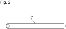
- Fig. 2 is a perspective view of the hollow acetate tube 20.
- three hollow filters are obtained by dividing the hollow acetate tube 20 equally into three along a longitudinal direction.
- the hollow acetate tube 20 is a hollow tube formed from a material called acetate.
- a raw material of the hollow acetate tube 20 is cellulose.
- cellulose obtained from wood can be used.
- Cellulose is reacted with acetic acid to produce cellulose acetate (also called acetyl cellulose or acetate), and cellulose acetate is dissolved in a solvent such as acetone, injected through thin holes, and dried using warm air to form fiber.
- the fiber is spun to form a bundle called tow.
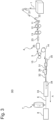
- FIG. 3 is a conceptual diagram showing the manufacturing process of the hollow acetate tube 20.
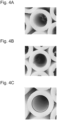
- Figs. 4A to 4C are perspective views showing an example of a defective product of the hollow acetate tube 20.
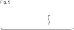
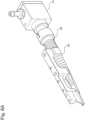
- Fig. 5 is a top view of a mandrel 34.
- Figs. 6A to 6C are perspective views showing a main part of the hollow acetate tube manufacturing apparatus 30.
- an acetate tow 1 delivered from a package of the acetate tow 1 receives air discharged from a first banding jet 21 and a second banding jet 22 and is made uniform and spread to a predetermined width. Afterward, the acetate tow 1 passes through pretension rollers 11, blooming rollers 12, stretch rollers 13 and a third banding jet 23 and proceeds toward a liquid addition booth 4.
- the acetate tow 1 is pretreated by impregnating the acetate tow with triacetin as a plasticizer in the liquid addition booth 4 to form a pretreated acetate tow 5.
- the pretreated acetate tow 5 is sent to a transport jet 31 via nip rolls 15 and a delivery roller 14.
- the pretreated acetate tow 5 receives compressed air. As a result, the pretreated acetate tow 5 is made uniform and conveyed into an internal space of the transport jet 31 extending along the longitudinal direction. When conveyed through the transport jet 31, the pretreated acetate tow 5 changes from a wide band shape to a substantially cylindrical rod-like shape through a mandrel holder 35.
- the internal space of the transport jet 31 extends substantially parallel to a transfer direction A of an uncut continuous hollow acetate tube 6 manufactured by the hollow acetate tube manufacturing apparatus 30.
- the pretreated acetate tow 5 flows out from an outlet opening of the transport jet 31 and is introduced into a tongue 32 via a trumpet guide 26 and compressed, thereby substantially determining an outer shape of the uncut continuous hollow acetate tube 6.
- the mandrel holder 35 and the mandrel 34 held by the mandrel holder 35 are arranged within the transport jet 31, the trumpet guide 26, the tongue 32 and a thermoforming part 33, and a hollow portion of the uncut continuous hollow acetate tube 6 is formed.
- the thermoforming part 33 steam is applied to the pretreated acetate tow 5, and by heat of the steam, the pretreated acetate tow 5 is rapidly plasticized and solidified, to form the uncut continuous hollow acetate tube 6.
- a filter cutting part 7 located downstream of the thermoforming part 33 cuts the uncut continuous hollow acetate tube 6 to a predetermined length with a knife, forms the hollow acetate tube 20, and sends the tube to an inspection unit 8.
- the inspection unit 8 optically inspects the hollow acetate tube 20.
- the inspection unit 8 is a member for rejecting defective products of the hollow acetate tube 20.
- the inspection unit 8 optically detects a state of an end of the hollow acetate tube 20 and inspects presence or absence of molding defects.
- Figs. 4A to 4C show examples of the defective product of the hollow acetate tube 20 having the end at which a manufacturing defect occurs.
- fluffing occurs on an inner circumference of the hollow acetate tube 20.
- a protrusion occurs on the inner circumference of the hollow acetate tube 20 and results in a molding defect.
- an inner circumferential circle of the hollow acetate tube 20 deviates from a predetermined shape (thick line).
- the inspection unit 8 merely inspects only one end of the hollow acetate tube 20, the defective products cannot completely be rejected. That is, the inspection unit 8 cannot detect a defective product in which a molding defect occurs only around a center of the hollow acetate tube 20 in the longitudinal direction and in which no molding defect appears at the end of the hollow acetate tube. Such a defective product of the hollow acetate tube 20 not detected by the inspection unit 8 is rejected, for example, by sample inspection with human power in a post-process of the hollow filter manufacturing process.
- the rejection of the defective product of the hollow acetate tube 20 referred to in the present disclosure means that the molding defect determined by the inspection unit 8 is rejected, and a rejection rate of defective products indicates a rate of a number of defective products determined as molding defects by the inspection unit 8 and rejected out of a total number of the hollow acetate tubes 20.
- the hollow acetate tube 20 that has passed through the inspection unit 8 is sent to a defective product storage or normal product storage (not shown).
- the hollow acetate tube 20 determined to be defective in the inspection unit 8 is sent to the defective product storage, and the hollow acetate tube 20 from which no molding defect is detected in the inspection unit 8 is sent to the normal product storage. Only the hollow acetate tubes 20 accumulated in the normal product storage are sent to a post-forming process of the hollow filter.
- the mandrel 34 is a metal core and is used to form a hollow portion of the hollow acetate tube 20 in the hollow acetate tube manufacturing apparatus 30.
- Fig. 6A is a view showing an excerpt including the transport jet 31, the trumpet guide 26, and the tongue 32.
- the transport jet 31, the trumpet guide 26 and the tongue 32 are also collectively referred to as a tongue part.
- Fig. 6B is a view showing an excerpt including the mandrel holder 35 and the mandrel 34.
- Fig. 6C is a view showing an excerpt including the tongue part and the thermoforming part 33.
- the transport jet 31, the trumpet guide 26 and the tongue 32 are arranged in this order substantially parallel to the transfer direction A.
- the mandrel 34 held in a rod-shaped portion of the mandrel holder 35 extends substantially parallel to the transfer direction A.
- the mandrel holder 35 and the mandrel 34 held by the mandrel holder 35 are arranged within the transport jet 31, the trumpet guide 26, the tongue 32 and the thermoforming part 33.
- the pretreated acetate tow 5 is introduced from an inlet opening of the transport jet 31, subjected to compressed air and made uniform.
- the pretreated acetate tow 5 is evenly disposed around the mandrel holder 35 due to influence of compressed air, changes from a wide band shape to a substantially cylindrical rod shape and flows out from the outlet opening of the transport jet 31.
- the pretreated acetate tow 5 is narrowed down around the mandrel holder 35 with the trumpet guide 26 and compressed around the mandrel holder 35 with the tongue 32, thereby defining a hollow in the tow.
- the pretreated acetate tow 5 is plasticized and solidified around the mandrel 34 with steam sprayed from a plurality of holes (not shown) arranged in the thermoforming part 33, to form the uncut continuous hollow acetate tube 6.
- the manufactured hollow filter is combined with the smokeable material 111 wrapped in the first wrapping paper 112 and the filter portion 115 prepared according to respective predetermined configurations and wrapped in the second wrapping paper 113, to couple respective members. Furthermore, by applying the lip release agent 117 to the outer surface of the second wrapping paper 113 in the vicinity of the end of the second wrapping paper on the filter portion 115 side, the consumable material 110 shown in Fig. 1 is manufactured.
- Fig. 7A is an enlarged view showing the surface of the mandrel 34 before being used in the hollow acetate tube manufacturing apparatus 30.
- Fig. 7B is an enlarged view showing the surface of the mandrel 34 after being used in the hollow acetate tube manufacturing apparatus 30.
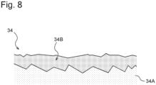
- Fig. 8 is a conceptual diagram showing a coating on the surface of the mandrel 34.
- the surface of an unused metal mandrel body 34A is provided with unevenness by blasting.
- the mandrel body 34A can maintain constant unevenness even after being used for a certain time or can maintain the constant unevenness even if worn.
- FIG. 7B after attaching the mandrel body 34A to the mandrel holder 35 and driving the hollow acetate tube manufacturing apparatus 30 for a predetermined time, the mandrel body 34A is worn in contact with the pretreated acetate tow 5 and has reduced unevenness on the surface of the mandrel body.
- various coatings 34B are applied to the surface of the metal mandrel body 34A.
- three types of mandrels 34 are manufactured by performing three types of processing on the surface of the mandrel body 34A. Hereinafter, each of these three examples will be described.
- a first example provides a mandrel 34 obtained by blasting the surface of a metal mandrel body 34A, and then performing composite resin processing described in literature ( Japanese Patent No. 3905730) of NIKKEN COATING INDUSTRY CO., LTD . to form a coating 34B on the surface.
- Japanese Patent No. 3905730 Japanese Patent No. 3905730
- NIKKEN COATING INDUSTRY CO., LTD to form a coating 34B on the surface.
- a manufacturing process of the coating 34B according to the first example will be described.
- the process includes pretreating the surface of the metal mandrel body 34A.
- Such pretreatment includes a first step of dry heating the mandrel body 34A, for example, at 400°C. Consequently, dirt such as oil content adhered to the surface of the mandrel body 34A is removed.
- the pretreatment includes a second step of blasting the surface, for example, with alumina. Consequently, other impurities remaining on the surface of the mandrel body 34A are removed and the unevenness shown in Fig. 7A is formed.
- the blasting is not limited to alumina, but may be fine particles of sand, metal, ceramic, or the like as long as it can be hit against the surface.
- the process includes subjecting the surface of the mandrel body 34A to surface treatment.
- the surface treatment includes a first step of applying a primer for adhering a composite resin to the surface of the mandrel body 34A.
- the surface treatment includes a second step of firing the mandrel body 34A with the primer applied thereto, for example, at 400°C for 60 minutes. Consequently, the surface of the mandrel body 34A and a primer layer adhere to each other.
- the process includes applying the composite resin to the surface of the mandrel body 34A.
- the composite resin is a mixture of one or more resins selected from the group consisting of a PEEK resin, a PEKK resin, a PPS resin and a PES resin and a fluorine resin.
- the process includes applying this composite resin onto the primer layer formed on the surface of the mandrel body 34A.
- the applying can be performed by a known coating method such as electrostatic powder coating, flow immersion, or spray coating.
- a coating method such as electrostatic powder coating, flow immersion, or spray coating.
- surface roughness of a composite resin film as the coating 34B formed can be set to a desired value.
- the blending ratio of the composite resin and the film thickness are adjusted such that a surface roughness Ra of the composite resin film as the coating 34B is in a range of 15 ⁇ m to 40 ⁇ m.
- the thickness of the composite resin film is from 50 ⁇ m to 200 ⁇ m.
- the process includes firing the applied composite resin in a firing furnace.
- the composite resin is fired, for example, at 420°C (melting temperature) for 60 minutes.
- the composite resin is melted and adheres to the primer layer.
- the composite resin film integrally adhered to the primer layer is cooled to cure the composite resin, thereby completing the coating 34B according to the first example.
- the composite resin film as the coating 34B has a surface formed in an uneven shape and is provided with slipperiness by a fluorine resin and formed integrally adhering to the surface of the mandrel body 34A.
- a second example provides a mandrel 34 obtained by blasting the surface of a metal mandrel body 34A, and then performing resin processing with a PEEK resin to form a coating 34B on the surface.
- a manufacturing process of the coating 34B according to the second example will be described.
- the process includes subjecting the surface of the metal mandrel body 34A to pretreatment and surface treatment.
- the pretreatment and surface treatment are the same as the treatments described in the first example.
- the process includes applying the PEEK resin onto a primer layer formed on the surface of the mandrel body 34A by the coating method described in the first example.
- the process includes firing the applied PEEK resin in a firing furnace.
- the PEEK resin is fired in the same manner as in the first example, so that a PEEK resin is melted and adheres to the primer layer.
- the process includes cooling the PEEK resin film integrally adhered to the primer layer to cure the PEEK resin, thereby completing the coating 34B according to the second example.
- a third example provides a mandrel 34 obtained by subjecting the surface of a metal mandrel body 34A to processing called Blastron (registered trademark) of Chiyoda Dai-ichi Kogyo Co., Ltd. to form a coating 34B.
- Blastron registered trademark
- Chiyoda Dai-ichi Kogyo Co., Ltd. a manufacturing process of the coating 34B according to the third example will be described.
- the process includes pretreating the surface of the metal mandrel body 34A.
- This pretreatment includes a first step of dry heating the mandrel body 34A, for example, at 400°C. Consequently, dirt such as oil content adhered to the surface of the mandrel body 34A is removed.
- the pretreatment includes a second step of blasting the surface, for example, with alumina. Consequently, other impurities remaining on the surface of the mandrel body 34A are removed and the unevenness shown in Fig. 7A is formed.
- the process includes subjecting the surface of the mandrel body 34A to carbide hard chromium plating, to form a carbide hard chromium plating film. Subsequently, the process includes blasting the carbide hard chromium plating film formed on the surface of the mandrel body 34A, for example, with alumina, to complete the coating 34B according to the third example.
- the coating 34B according to the third example is formed by processing called Blastron #120.
- a numerical after Blastron indicates surface roughness of the coating 34B.
- Blastron #200 indicates a surface roughness Ra of about 0.45 ⁇ m
- Blastron #400 indicates a surface roughness Ra of about 0.35 ⁇ m.
- Blastron #120 to #440 may be used as the coating 34B.
- the mandrel according to the first comparative example is an existing mandrel manufactured by Hauni Maschinenbau AG with a resin coating formed on the surface of a mandrel body. Furthermore, the mandrel according to the second comparative example is a mandrel with the surface of a mandrel body subjected only to blasting.
- the hollow acetate tube manufacturing apparatus 30 using the mandrels 34 according to the first to third examples and the hollow acetate tube manufacturing apparatus using the mandrels according to the first and second comparative examples were each driven to use limit of the mandrel, and time to the use limit, a reason for the use limit, and a rejection rate of defective products were verified.
- Fig. 9 is a table showing experimental results when the hollow acetate tube manufacturing apparatus 30 using the mandrels 34 according to the first to third examples and the hollow acetate tube manufacturing apparatus using the mandrels according to the first and second comparative examples were driven to the use limit of the mandrel.
- a mechanical speed of each hollow acetate tube manufacturing apparatus that is, a moving speed of the hollow acetate tube is 500 m/min, and various settings are on the same conditions.
- the mandrel use limit is defined after start of use of a new mandrel until a machine cannot be operated or rejection of defective products frequently occurs, due to the mandrel. Furthermore, the rejection rate of defective products indicates the rejection rate of defective products when a hollow acetate tube is manufactured for 15 minutes after the start of use of the new mandrel.
- the defective product rejection rate in the first example was 1.02%.
- the third example (carbide hard chromium plating)
- fluffing or deformation of the hollow acetate tube frequently occurred, and the mandrel reached the limit of use. At this time, any wear was not observed on the surface of the mandrel.
- the defective product rejection rate in the second example was 0.86%.
- the defective product rejection rate in the first comparative example was 1.67%.
- the defective product rejection rate was from 20 to 30%.
- a large number of defective products were generated, and only 70 to 80% of the manufactured hollow acetate tubes 20 could be manufactured as non-defective products.
- the hollow acetate tube manufacturing apparatus 30 using the mandrel 34 according to the first example and the hollow acetate tube manufacturing apparatus using the mandrel according to the first comparative example were each driven for six hours, and a rejection rate for each rejection content of defective products was verified.
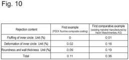
- Fig. 10 is a table showing experimental results when the hollow acetate tube manufacturing apparatus 30 using the mandrel 34 according to the first example and the hollow acetate tube manufacturing apparatus using the mandrel according to the first comparative example were each driven for six hours.
- the mechanical speed of each hollow acetate tube manufacturing apparatus that is, the moving speed of the hollow acetate tube, is 500 m/min, and various settings are on the same conditions.
- fluffing of an inner circle indicates the defective product shown in Fig. 4A .
- Deformation of the inner circle indicates the defective product shown in Fig. 4B .
- Roundness and wall thickness indicate the defective product shown in Fig. 4C .
- the defective product rejection rate due to the fluffing of the inner circle was 0%
- the defective product rejection rate due to the deformation of the inner circle was 0.02%
- the defective product rejection rate due to the roundness and wall thickness was 0.09%.
- the defective product rejection rate when driving the hollow acetate tube manufacturing apparatus 30 using the mandrel 34 according to the first example for six hours was 0.11 % in total.
- the defective product rejection rate due to the fluffing of the inner circle was 0.01%
- the defective product rejection rate due to the deformation of the inner circle was 0.16%
- the defective product rejection rate due to the roundness and wall thickness was 0.19%.
- the defective product rejection rate when driving the hollow acetate tube manufacturing apparatus using the mandrel according to the first comparative example for six hours was 0.36% in total.
- the inventors according to the present disclosure have found that a large number of bubbles 34C were formed inside a composite resin film as a coating 34B of the mandrel 34 according to the first example.
- the bubbles 34C are considered to contribute to maintaining the surface unevenness of the mandrel body 34A against wear due to contact with the pretreated acetate tow 5. Specifically, since the bubbles 34C having a certain volume are crushed, the wear on the coating 34B occurs discontinuously rather than continuously, so that new unevenness is considered to appear.
- the bubbles 34C have a minimum delivery length of 5 ⁇ m or more.
- the composite resin film as the coating 34B of the mandrel 34 according to the first example retains the surface roughness Ra even after use of the mandrel 34. Specifically, after driving the hollow acetate tube manufacturing apparatus 30 using the mandrel 34 according to the first example for 10 hours, the surface roughness Ra of the composite resin film as the coating 34B indicated a range of 15 ⁇ m to 40 ⁇ m.
- the results obtained according to the first example were the endurance time until tow clogging being about 50 hours, and the defective product rejection rate of 1.02% in 15 minutes evaluation.
- the results are desirable values as compared to the second comparative example.
- an occurrence rate of nonconforming products determined to be molding defects and rejected by the inspection unit 8 in 15 minutes is in a range of 0.86% or more to 1.67% or less.
- this numerical range is based on the evaluation by the inspection unit 8 that optically inspects only the end of the hollow acetate tube 20, and it is assumed that more nonconforming products are actually generated.
- the third example can largely reduce the defective product rejection rate but lacks in durability.
- the first example shows results that significantly exceed the other two examples in durability.
- Figs. 12A to 12C show evaluations of cross sections of coatings 34B according to the first to third examples, respectively.
- Each cross section depends on how to take a cut surface, but general tendency can be known. Particularly, in the first example, large unevenness is formed on the surface of the mandrel body 34A, to which the above-described bubbles 34C are considered to contribute.
Abstract
Description
- The present disclosure relates to a mandrel for use in a manufacturing apparatus for manufacturing a hollow acetate tube and a manufacturing method of a mandrel, and an apparatus and method for manufacturing a hollow acetate tube.
- Conventionally, in a field of flavor aspirators, a hollow filter constituting a part of a consumable material to be smoked is manufactured by manufacturing a hollow acetate tube and cutting this tube. Then, a metal core called a mandrel is used in an apparatus for manufacturing the hollow acetate tube. See, for example, PTL 1.
- PTL 1:
Japanese Translation of PCT International Application Publication No. 2019-502369 - However, in a process of manufacturing a hollow acetate tube, a mandrel may deteriorate. Specifically, a manufacturing apparatus may be stopped by a tow clogged in the manufacturing apparatus, which is a material of the hollow acetate tube, due to wear on the surface of the mandrel, or a defective product may occur among manufactured hollow acetate tubes.
- The present disclosure provides a mandrel for use in a manufacturing apparatus for manufacturing a hollow acetate tube and a manufacturing method of thereof, and an apparatus and method for manufacturing a hollow acetate tube, with improved durability as a component and improved quality of a manufactured product.
- A first aspect of the present disclosure provides a mandrel for use in a manufacturing apparatus for manufacturing a hollow acetate tube to be applied to a heating type tobacco product, the mandrel comprising a metal mandrel body, and a composite resin film formed on the surface of the mandrel body by melting a composite resin including one or more resins selected from the group consisting of a PEEK resin, a PEKK resin, a PPS resin and a PES resin together with a fluorine resin, wherein the composite resin film includes bubbles inside the film.
- In the above first aspect, the surface of the mandrel is coated with the composite resin film made of a predetermined material, and bubbles are formed within the composite resin film. According to the first aspect, favorable results are obtained in an endurance time of the mandrel and a rejection rate of the hollow acetate tube.
- A second aspect of the present disclosure provides the mandrel in the above first aspect, wherein the composite resin film has a thickness of 50 µm to 200 µm.
- In the above second aspect, the thickness of a layer of the composite resin film formed on the surface of the mandrel is from 50 µm to 200 µm. According to the second aspect, more favorable results are obtained in the endurance time of the mandrel and the rejection rate of the hollow acetate tube.
- A third aspect of the present disclosure provides the mandrel in the above first or second aspect, wherein the bubbles have a minimum delivery length of 5 µm or more.
- In the above third aspect, the minimum delivery length of the bubbles formed in the layer of the composite resin film is 5 µm or more. According to the third aspect, more favorable results are obtained in the endurance time of the mandrel and the rejection rate of the hollow acetate tube.
- A fourth aspect of the present disclosure provides the mandrel in the above first to third aspects, wherein the composite resin film has a surface roughness Ra of 15 µm to 40 µm.
- In the fourth aspect, the surface roughness Ra of the composite resin film is from 15 µm to 40 µm. According to the fourth aspect, more favorable results are obtained in the endurance time of the mandrel and the rejection rate of the hollow acetate tube.
- A fifth aspect of the present disclosure provides the mandrel in the fourth aspect, wherein the composite resin film exhibits the surface roughness Ra of 15 µm to 40 µm after being rubbed over 10 hours by the hollow acetate tube moving at a speed of 200 m/min to 300 m/min by driving the manufacturing apparatus.
- In the fifth aspect, after the manufacturing apparatus is driven for N hours to manufacture the hollow acetate tube, the composite resin film keeps the surface roughness Ra of 15 µm to 40 µm. According to the fifth aspect, more favorable results are obtained in the endurance time of the mandrel and the rejection rate of the hollow acetate tube.
- A sixth aspect of the present disclosure provides a mandrel for use in a manufacturing apparatus for manufacturing a hollow acetate tube to be applied to a heating type tobacco product, the mandrel comprising a metal mandrel body, and a carbide hard chromium plating film formed on the surface of the mandrel body.
- In the sixth aspect, the surface of the metal mandrel body is coated with carbide hard chromium plating. According to the sixth aspect, favorable results are obtained in the endurance time of the mandrel and the rejection rate of the hollow acetate tube.
- A seventh aspect of the present disclosure provides an apparatus for manufacturing a hollow acetate tube, comprising the mandrel according to the above first to sixth aspects.
- According to the above seventh aspect, it is possible to provide the apparatus for manufacturing the hollow acetate tube that obtains a favorable result in the rejection rate of the hollow acetate tube.
- An eighth aspect of the present disclosure provides a method for manufacturing a hollow acetate tube to be applied to a heating type tobacco product, the method comprising: rubbing the surface of a mandrel with fiber as a material of the hollow acetate tube moving in a manufacturing apparatus for manufacturing the hollow acetate tube, the mandrel for use in the manufacturing apparatus, comprising a metal mandrel body, and a composite resin film formed on the surface of the mandrel body by melting a composite resin including one or more resins selected from the group consisting of a PEEK resin, a PEKK resin, a PPS resin and a PES resin together with a fluorine resin, wherein the composite resin film includes bubbles inside the film.
- The above eighth aspect includes rubbing, with the fiber as the material of the hollow acetate tube, the surface of the metal mandrel body coated with the composite resin film made of a predetermined material and including the bubbles formed within the composite resin film. According to the eighth aspect, favorable results are obtained in the endurance time of the mandrel and the rejection rate of the hollow acetate tube.
- A ninth aspect of the present disclosure provides a method for manufacturing a hollow acetate tube to be applied to a heating type tobacco product, the method comprising: rubbing the surface of a mandrel with fiber as a material of the hollow acetate tube moving in a manufacturing apparatus for manufacturing the hollow acetate tube, the mandrel for use in a component of the manufacturing apparatus, comprising a metal mandrel body, and a carbide hard chromium plating film formed on the surface of the mandrel body.
- The ninth aspect includes rubbing, with the fiber as the material of the hollow acetate tube, the surface of the metal mandrel body coated with the carbide hard chromium plating film. According to the ninth aspect, favorable results are obtained in the endurance time of the mandrel and the rejection rate of the hollow acetate tube.
- A tenth aspect of the present disclosure provides a method for manufacturing a mandrel for use in a manufacturing apparatus for manufacturing a hollow acetate tube to be applied to a heating type tobacco product, the method comprising: blasting the surface of a metal mandrel body, and mixing, applying and melting one or more resins selected from the group consisting of a PEEK resin, a PEKK resin, a PPS resin and a PES resin together with a fluorine resin to form a composite resin film on the blasted surface.
- The above tenth aspect includes blasting the surface of the metal mandrel body and then coating the surface with the composite resin film formed by a predetermined process. According to the tenth aspect, favorable results are obtained in the endurance time of the mandrel and the rejection rate of the hollow acetate tube.
- An eleventh aspect of the present disclosure provides a method for manufacturing a mandrel for use in a manufacturing apparatus for manufacturing a hollow acetate tube to be applied to a heating type tobacco product, the method comprising blasting the surface of a metal mandrel body and forming a carbide hard chromium plating film on the blasted surface.
- The eleventh aspect includes blasting the surface of the metal mandrel body and then coating the surface with the carbide hard chromium plating film. According to the eleventh aspect, favorable results are obtained in the endurance time of the mandrel and the rejection rate of the hollow acetate tube.
-
-
Fig. 1 is a schematic cross-sectional side view showing an example of a consumable material of a flavor aspirator. -
Fig. 2 is a perspective view showing a hollow acetate tube. -
Fig. 3 is a conceptual diagram showing a manufacturing process of the hollow acetate tube. -
Fig. 4A is a perspective view showing an example of a defective product of the hollow acetate tube. -
Fig. 4B is a perspective view showing an example of the defective product of the hollow acetate tube. -
Fig. 4C is a perspective view showing an example of the defective product of the hollow acetate tube. -
Fig. 5 is a top view showing a mandrel. -
Fig. 6A is a perspective view showing a main part of a hollow acetate tube manufacturing apparatus. -
Fig. 6B is a perspective view showing the main part of the hollow acetate tube manufacturing apparatus. -
Fig. 6C is a perspective view showing the main part of the hollow acetate tube manufacturing apparatus. -
Fig. 7A is an enlarged view showing the surface of the mandrel before use. -
Fig. 7B is an enlarged view showing the surface of the mandrel after the use. -
Fig. 8 is a conceptual diagram showing a coating of the mandrel surface. -
Fig. 9 is a table showing experimental results when a hollow acetate tube manufacturing apparatus using mandrels according to first to third examples and a hollow acetate tube manufacturing apparatus using mandrels according to first and second comparative examples are driven to limit of use of the mandrel. -
Fig. 10 is a table showing experimental results when the hollow acetate tube manufacturing apparatus using the mandrel according to the first example and the hollow acetate tube manufacturing apparatus using the mandrel according to the first comparative example are driven for six hours. -
Fig. 11 is a conceptual diagram showing the surface of the mandrel according to the first example. -
Fig. 12A is a cross-sectional view showing the surface of the mandrel according to the first example. -
Fig. 12B is a cross-sectional view showing the surface of the mandrel according to the second example. -
Fig. 12C is a cross-sectional view showing the surface of the mandrel according to the third example. - Hereinafter, embodiments of the present disclosure will be described with reference to the drawings. In the drawings described below, the same or corresponding components are denoted with the same reference sign and duplicate descriptions are omitted.
-
Fig. 1 is a schematic cross-sectional side view of aconsumable material 110, which is an example of a consumable material for use in a flavor aspirator. The flavor aspirator and theconsumable material 110 may constitute a smoking system. In the example shown inFig. 1 , theconsumable material 110 includes asmokeable material 111, atubular member 114, ahollow filter portion 116, and afilter portion 115. Thesmokeable material 111 is wrapped infirst wrapping paper 112. Thetubular member 114, thehollow filter portion 116, and thefilter portion 115 are wrapped insecond wrapping paper 113 that is different from thefirst wrapping paper 112. Thesecond wrapping paper 113 is also for wrapping a part of thefirst wrapping paper 112 that wraps thesmokeable material 111. Thus, thetubular member 114, thehollow filter portion 116, and thefilter portion 115 are coupled to thesmokeable material 111. However, thesecond wrapping paper 113 may be omitted, and thefirst wrapping paper 112 may be used to couple thetubular member 114, thehollow filter portion 116, and thefilter portion 115 to thesmokeable material 111. Alip release agent 117 is applied to an outer surface of thesecond wrapping paper 113 in the vicinity of an end of thesecond wrapping paper 113 on afilter portion 115 side to prevent a user's lips from sticking to thesecond wrapping paper 113. A portion of theconsumable material 110 to which thelip release agent 117 is applied functions as a mouthpiece of theconsumable material 110. Theconsumable material 110 is an example of heating type tobacco of the present disclosure. - The
smokeable material 111 may include, for example, a flavor source such as tobacco and an aerosol source. Furthermore, thefirst wrapping paper 112 that wraps thesmokeable material 111 may be a breathable sheet member. Thetubular member 114 may be a paper tube or a hollow filter. In the example shown inFig. 1 , theconsumable material 110 includes thesmokeable material 111, thetubular member 114, thehollow filter portion 116, and thefilter portion 115, but theconsumable material 110 is not limited to this configuration. - The
tubular member 114 and thehollow filter portion 116 of theconsumable material 110 may be formed integrally. Hereinafter, in the present disclosure, thetubular member 114 and thehollow filter portion 116 will be described as an integral hollow filter. The hollow filter in which thetubular member 114 and thehollow filter portion 116 are integrally formed is an example of the filter of the present disclosure. - The hollow filter is formed by cutting a
hollow acetate tube 20 into a predetermined length.Fig. 2 is a perspective view of thehollow acetate tube 20. As an example, three hollow filters are obtained by dividing thehollow acetate tube 20 equally into three along a longitudinal direction. - The
hollow acetate tube 20 is a hollow tube formed from a material called acetate. A raw material of thehollow acetate tube 20 is cellulose. For example, cellulose obtained from wood can be used. Cellulose is reacted with acetic acid to produce cellulose acetate (also called acetyl cellulose or acetate), and cellulose acetate is dissolved in a solvent such as acetone, injected through thin holes, and dried using warm air to form fiber. The fiber is spun to form a bundle called tow. - Hereinafter, a manufacturing process of the
hollow acetate tube 20 using a hollow acetatetube manufacturing apparatus 30 will be described.Fig. 3 is a conceptual diagram showing the manufacturing process of thehollow acetate tube 20.Figs. 4A to 4C are perspective views showing an example of a defective product of thehollow acetate tube 20.Fig. 5 is a top view of amandrel 34.Figs. 6A to 6C are perspective views showing a main part of the hollow acetatetube manufacturing apparatus 30. - As shown in
Fig. 3 , an acetate tow 1 delivered from a package of the acetate tow 1 receives air discharged from afirst banding jet 21 and asecond banding jet 22 and is made uniform and spread to a predetermined width. Afterward, the acetate tow 1 passes throughpretension rollers 11, bloomingrollers 12,stretch rollers 13 and athird banding jet 23 and proceeds toward aliquid addition booth 4. The acetate tow 1 is pretreated by impregnating the acetate tow with triacetin as a plasticizer in theliquid addition booth 4 to form a pretreatedacetate tow 5. The pretreatedacetate tow 5 is sent to atransport jet 31 via nip rolls 15 and adelivery roller 14. - In the
transport jet 31, the pretreatedacetate tow 5 receives compressed air. As a result, the pretreatedacetate tow 5 is made uniform and conveyed into an internal space of thetransport jet 31 extending along the longitudinal direction. When conveyed through thetransport jet 31, the pretreatedacetate tow 5 changes from a wide band shape to a substantially cylindrical rod-like shape through amandrel holder 35. The internal space of thetransport jet 31 extends substantially parallel to a transfer direction A of an uncut continuoushollow acetate tube 6 manufactured by the hollow acetatetube manufacturing apparatus 30. - The pretreated
acetate tow 5 flows out from an outlet opening of thetransport jet 31 and is introduced into atongue 32 via atrumpet guide 26 and compressed, thereby substantially determining an outer shape of the uncut continuoushollow acetate tube 6. Themandrel holder 35 and themandrel 34 held by themandrel holder 35 are arranged within thetransport jet 31, thetrumpet guide 26, thetongue 32 and athermoforming part 33, and a hollow portion of the uncut continuoushollow acetate tube 6 is formed. In thethermoforming part 33, steam is applied to the pretreatedacetate tow 5, and by heat of the steam, the pretreatedacetate tow 5 is rapidly plasticized and solidified, to form the uncut continuoushollow acetate tube 6. - A
filter cutting part 7 located downstream of thethermoforming part 33 cuts the uncut continuoushollow acetate tube 6 to a predetermined length with a knife, forms thehollow acetate tube 20, and sends the tube to aninspection unit 8. - The
inspection unit 8 optically inspects thehollow acetate tube 20. Theinspection unit 8 is a member for rejecting defective products of thehollow acetate tube 20. Theinspection unit 8 optically detects a state of an end of thehollow acetate tube 20 and inspects presence or absence of molding defects. -
Figs. 4A to 4C show examples of the defective product of thehollow acetate tube 20 having the end at which a manufacturing defect occurs. InFig. 4A , fluffing occurs on an inner circumference of thehollow acetate tube 20. InFig. 4B , a protrusion occurs on the inner circumference of thehollow acetate tube 20 and results in a molding defect. InFIG. 4C , an inner circumferential circle of thehollow acetate tube 20 deviates from a predetermined shape (thick line). - Since the
inspection unit 8 merely inspects only one end of thehollow acetate tube 20, the defective products cannot completely be rejected. That is, theinspection unit 8 cannot detect a defective product in which a molding defect occurs only around a center of thehollow acetate tube 20 in the longitudinal direction and in which no molding defect appears at the end of the hollow acetate tube. Such a defective product of thehollow acetate tube 20 not detected by theinspection unit 8 is rejected, for example, by sample inspection with human power in a post-process of the hollow filter manufacturing process. - Hereinafter, the rejection of the defective product of the
hollow acetate tube 20 referred to in the present disclosure means that the molding defect determined by theinspection unit 8 is rejected, and a rejection rate of defective products indicates a rate of a number of defective products determined as molding defects by theinspection unit 8 and rejected out of a total number of thehollow acetate tubes 20. - The
hollow acetate tube 20 that has passed through theinspection unit 8 is sent to a defective product storage or normal product storage (not shown). Thehollow acetate tube 20 determined to be defective in theinspection unit 8 is sent to the defective product storage, and thehollow acetate tube 20 from which no molding defect is detected in theinspection unit 8 is sent to the normal product storage. Only thehollow acetate tubes 20 accumulated in the normal product storage are sent to a post-forming process of the hollow filter. - As shown in
Fig. 5 , themandrel 34 is a metal core and is used to form a hollow portion of thehollow acetate tube 20 in the hollow acetatetube manufacturing apparatus 30. - With reference to
Figs. 6A to 6C , a configuration of the main part of the hollow acetatetube manufacturing apparatus 30 shown inFig. 3 will be described.Fig. 6A is a view showing an excerpt including thetransport jet 31, thetrumpet guide 26, and thetongue 32. Hereinafter, thetransport jet 31, thetrumpet guide 26 and thetongue 32 are also collectively referred to as a tongue part.Fig. 6B is a view showing an excerpt including themandrel holder 35 and themandrel 34.Fig. 6C is a view showing an excerpt including the tongue part and thethermoforming part 33. - As shown in
Figs. 6A to 6C , thetransport jet 31, thetrumpet guide 26 and thetongue 32 are arranged in this order substantially parallel to the transfer direction A. Themandrel 34 held in a rod-shaped portion of themandrel holder 35 extends substantially parallel to the transfer direction A. Here, themandrel holder 35 and themandrel 34 held by themandrel holder 35 are arranged within thetransport jet 31, thetrumpet guide 26, thetongue 32 and thethermoforming part 33. - The pretreated
acetate tow 5 is introduced from an inlet opening of thetransport jet 31, subjected to compressed air and made uniform. When conveyed in thetransport jet 31, the pretreatedacetate tow 5 is evenly disposed around themandrel holder 35 due to influence of compressed air, changes from a wide band shape to a substantially cylindrical rod shape and flows out from the outlet opening of thetransport jet 31. - Subsequently, when conveyed in the
trumpet guide 26 and thetongue 32, the pretreatedacetate tow 5 is narrowed down around themandrel holder 35 with thetrumpet guide 26 and compressed around themandrel holder 35 with thetongue 32, thereby defining a hollow in the tow. Afterward, when conveyed in thethermoforming part 33, the pretreatedacetate tow 5 is plasticized and solidified around themandrel 34 with steam sprayed from a plurality of holes (not shown) arranged in thethermoforming part 33, to form the uncut continuoushollow acetate tube 6. - As described above, only the
hollow acetate tube 20 accumulated in the normal product storage is sent to the post-forming process of the hollow filter. Then, the manufactured hollow filter is combined with thesmokeable material 111 wrapped in thefirst wrapping paper 112 and thefilter portion 115 prepared according to respective predetermined configurations and wrapped in thesecond wrapping paper 113, to couple respective members. Furthermore, by applying thelip release agent 117 to the outer surface of thesecond wrapping paper 113 in the vicinity of the end of the second wrapping paper on thefilter portion 115 side, theconsumable material 110 shown inFig. 1 is manufactured. - Next, with reference to
Figs. 7A, 7B , and8 , a structure of the surface of themandrel 34 will be described.Fig. 7A is an enlarged view showing the surface of themandrel 34 before being used in the hollow acetatetube manufacturing apparatus 30.Fig. 7B is an enlarged view showing the surface of themandrel 34 after being used in the hollow acetatetube manufacturing apparatus 30.Fig. 8 is a conceptual diagram showing a coating on the surface of themandrel 34. - As shown in
Fig. 7A , the surface of an unusedmetal mandrel body 34A is provided with unevenness by blasting. Themandrel body 34A can maintain constant unevenness even after being used for a certain time or can maintain the constant unevenness even if worn. As shown inFIG. 7B , after attaching themandrel body 34A to themandrel holder 35 and driving the hollow acetatetube manufacturing apparatus 30 for a predetermined time, themandrel body 34A is worn in contact with the pretreatedacetate tow 5 and has reduced unevenness on the surface of the mandrel body. - In the present disclosure, as shown in
Fig. 8 ,various coatings 34B are applied to the surface of themetal mandrel body 34A. In the embodiment of the present disclosure, three types ofmandrels 34 are manufactured by performing three types of processing on the surface of themandrel body 34A. Hereinafter, each of these three examples will be described. - A first example provides a
mandrel 34 obtained by blasting the surface of ametal mandrel body 34A, and then performing composite resin processing described in literature (Japanese Patent No. 3905730) of NIKKEN COATING INDUSTRY CO., LTD coating 34B on the surface. Hereinafter, a manufacturing process of thecoating 34B according to the first example will be described. - First, the process includes pretreating the surface of the
metal mandrel body 34A. Such pretreatment includes a first step of dry heating themandrel body 34A, for example, at 400°C. Consequently, dirt such as oil content adhered to the surface of themandrel body 34A is removed. The pretreatment includes a second step of blasting the surface, for example, with alumina. Consequently, other impurities remaining on the surface of themandrel body 34A are removed and the unevenness shown inFig. 7A is formed. The blasting is not limited to alumina, but may be fine particles of sand, metal, ceramic, or the like as long as it can be hit against the surface. - Next, the process includes subjecting the surface of the
mandrel body 34A to surface treatment. The surface treatment includes a first step of applying a primer for adhering a composite resin to the surface of themandrel body 34A. The surface treatment includes a second step of firing themandrel body 34A with the primer applied thereto, for example, at 400°C for 60 minutes. Consequently, the surface of themandrel body 34A and a primer layer adhere to each other. - Subsequently, the process includes applying the composite resin to the surface of the
mandrel body 34A. The composite resin is a mixture of one or more resins selected from the group consisting of a PEEK resin, a PEKK resin, a PPS resin and a PES resin and a fluorine resin. As an example, the PEEK resin and a PFA resin as the fluorine resin can be used as the composite resin, and a ratio of PEEK resin:PFA resin = about 80: about 20 can be adopted as a blending ratio. - Next, the process includes applying this composite resin onto the primer layer formed on the surface of the
mandrel body 34A. The applying can be performed by a known coating method such as electrostatic powder coating, flow immersion, or spray coating. By adjusting the blending ratio of the composite resin and a film thickness, surface roughness of a composite resin film as thecoating 34B formed can be set to a desired value. In the first example, the blending ratio of the composite resin and the film thickness are adjusted such that a surface roughness Ra of the composite resin film as thecoating 34B is in a range of 15 µm to 40 µm. As an example, the thickness of the composite resin film is from 50 µm to 200 µm. - Subsequently, the process includes firing the applied composite resin in a firing furnace. The composite resin is fired, for example, at 420°C (melting temperature) for 60 minutes. Thus, the composite resin is melted and adheres to the primer layer. Finally, the composite resin film integrally adhered to the primer layer is cooled to cure the composite resin, thereby completing the
coating 34B according to the first example. The composite resin film as thecoating 34B has a surface formed in an uneven shape and is provided with slipperiness by a fluorine resin and formed integrally adhering to the surface of themandrel body 34A. - A second example provides a
mandrel 34 obtained by blasting the surface of ametal mandrel body 34A, and then performing resin processing with a PEEK resin to form acoating 34B on the surface. Hereinafter, a manufacturing process of thecoating 34B according to the second example will be described. - First, the process includes subjecting the surface of the
metal mandrel body 34A to pretreatment and surface treatment. The pretreatment and surface treatment are the same as the treatments described in the first example. Next, the process includes applying the PEEK resin onto a primer layer formed on the surface of themandrel body 34A by the coating method described in the first example. - Subsequently, the process includes firing the applied PEEK resin in a firing furnace. The PEEK resin is fired in the same manner as in the first example, so that a PEEK resin is melted and adheres to the primer layer. Finally, the process includes cooling the PEEK resin film integrally adhered to the primer layer to cure the PEEK resin, thereby completing the
coating 34B according to the second example. - A third example provides a
mandrel 34 obtained by subjecting the surface of ametal mandrel body 34A to processing called Blastron (registered trademark) of Chiyoda Dai-ichi Kogyo Co., Ltd. to form acoating 34B. Hereinafter, a manufacturing process of thecoating 34B according to the third example will be described. - First, the process includes pretreating the surface of the
metal mandrel body 34A. This pretreatment includes a first step of dry heating themandrel body 34A, for example, at 400°C. Consequently, dirt such as oil content adhered to the surface of themandrel body 34A is removed. The pretreatment includes a second step of blasting the surface, for example, with alumina. Consequently, other impurities remaining on the surface of themandrel body 34A are removed and the unevenness shown inFig. 7A is formed. - Next, the process includes subjecting the surface of the
mandrel body 34A to carbide hard chromium plating, to form a carbide hard chromium plating film. Subsequently, the process includes blasting the carbide hard chromium plating film formed on the surface of themandrel body 34A, for example, with alumina, to complete thecoating 34B according to the third example. Specifically, thecoating 34B according to the third example is formed by processing called Blastron #120. Here, a numerical after Blastron indicates surface roughness of thecoating 34B. For example, Blastron #200 indicates a surface roughness Ra of about 0.45 µm, and Blastron #400 indicates a surface roughness Ra of about 0.35 µm. As thecoating 34B, Blastron #120 to #440 may be used. - Experiments were performed using a hollow acetate
tube manufacturing apparatus 30 in which mandrels 34 according to the first to third examples of the embodiment of the present disclosure described above were used, and a hollow acetate tube manufacturing apparatus in which mandrels according to first and second comparative examples were used. Experimental results will be described as follows. - The mandrel according to the first comparative example is an existing mandrel manufactured by Hauni Maschinenbau AG with a resin coating formed on the surface of a mandrel body. Furthermore, the mandrel according to the second comparative example is a mandrel with the surface of a mandrel body subjected only to blasting.
- First, the hollow acetate
tube manufacturing apparatus 30 using themandrels 34 according to the first to third examples and the hollow acetate tube manufacturing apparatus using the mandrels according to the first and second comparative examples were each driven to use limit of the mandrel, and time to the use limit, a reason for the use limit, and a rejection rate of defective products were verified. -
Fig. 9 is a table showing experimental results when the hollow acetatetube manufacturing apparatus 30 using themandrels 34 according to the first to third examples and the hollow acetate tube manufacturing apparatus using the mandrels according to the first and second comparative examples were driven to the use limit of the mandrel. Here, a mechanical speed of each hollow acetate tube manufacturing apparatus, that is, a moving speed of the hollow acetate tube is 500 m/min, and various settings are on the same conditions. - In
FIG. 9 , the mandrel use limit is defined after start of use of a new mandrel until a machine cannot be operated or rejection of defective products frequently occurs, due to the mandrel. Furthermore, the rejection rate of defective products indicates the rejection rate of defective products when a hollow acetate tube is manufactured for 15 minutes after the start of use of the new mandrel. - As shown in
Fig. 9 , in the first example (PEEK fluorine composite coating), after 48 hours from the start of use of the mandrel, tow clogging frequently occurred in a tongue unit due to wear on the surface of the mandrel, and the mandrel reached the limit of use. Furthermore, the defective product rejection rate in the first example was 1.02%. - Also, in the second example (PEEK coating), after four hours from the start of use of the mandrel, the tow clogging frequently occurred in the tongue unit due to wear on the surface of the mandrel, and the mandrel reached the limit of use. Furthermore, the defective product rejection rate in the second example was 0.94%.
- Furthermore, in the third example (carbide hard chromium plating), after five hours from the start of use of the mandrel, fluffing or deformation of the hollow acetate tube frequently occurred, and the mandrel reached the limit of use. At this time, any wear was not observed on the surface of the mandrel. The defective product rejection rate in the second example was 0.86%.
- Additionally, in the first comparative example (existing mandrel manufactured by Hauni Maschinenbau AG), after six hours from the start of use of the mandrel, the tow clogging frequently occurred in the tongue unit due to wear on the mandrel surface, and the mandrel reached the use limit. The defective product rejection rate in the first comparative example was 1.67%.
- Furthermore, in the second comparative example (surface blasted mandrel), after 0.2 hours from the start of use of the mandrel, fluffing or deformation of the hollow acetate tube occurred frequently, the tow clogging frequently occurred in the tongue unit, and the mandrel reached the use limit. In the second comparative example, the defective product rejection rate was from 20 to 30%. Specifically, in the second comparative example, a large number of defective products were generated, and only 70 to 80% of the manufactured
hollow acetate tubes 20 could be manufactured as non-defective products. - As seen from
Fig. 9 , according to the first to third examples, much better results can be obtained than in the second comparative example in terms of the mandrel use limit and the defective product rejection rate. Furthermore, according to the first example, better results can be obtained than in the first comparative example in terms of the mandrel use limit and the defective product rejection rate. Furthermore, according to the second and third examples, better results can be obtained than in the first comparative example in terms of the defective product rejection rate. - Next, the hollow acetate
tube manufacturing apparatus 30 using themandrel 34 according to the first example and the hollow acetate tube manufacturing apparatus using the mandrel according to the first comparative example were each driven for six hours, and a rejection rate for each rejection content of defective products was verified. -
Fig. 10 is a table showing experimental results when the hollow acetatetube manufacturing apparatus 30 using themandrel 34 according to the first example and the hollow acetate tube manufacturing apparatus using the mandrel according to the first comparative example were each driven for six hours. Here, the mechanical speed of each hollow acetate tube manufacturing apparatus, that is, the moving speed of the hollow acetate tube, is 500 m/min, and various settings are on the same conditions. - In
Fig. 10 , fluffing of an inner circle indicates the defective product shown inFig. 4A . Deformation of the inner circle indicates the defective product shown inFig. 4B . Roundness and wall thickness indicate the defective product shown inFig. 4C . - As shown in
Fig. 10 , in the first example (PEEK fluorine composite coating), the defective product rejection rate due to the fluffing of the inner circle was 0%, the defective product rejection rate due to the deformation of the inner circle was 0.02%, and the defective product rejection rate due to the roundness and wall thickness was 0.09%. As a result, the defective product rejection rate when driving the hollow acetatetube manufacturing apparatus 30 using themandrel 34 according to the first example for six hours was 0.11 % in total. - Furthermore, in the first comparative example (existing mandrel manufactured by Hauni Maschinenbau AG), the defective product rejection rate due to the fluffing of the inner circle was 0.01%, the defective product rejection rate due to the deformation of the inner circle was 0.16%, and the defective product rejection rate due to the roundness and wall thickness was 0.19%. As a result, the defective product rejection rate when driving the hollow acetate tube manufacturing apparatus using the mandrel according to the first comparative example for six hours was 0.36% in total.
- As seen from
Fig. 10 , in the first example, better results can be obtained than in the first comparative example in terms of each of rejection contents, and better results can be obtained than in the first comparative example in terms of the defective product rejection rate obtained by summing the rejection rates for each rejection content. - As shown in
Fig. 11 , the inventors according to the present disclosure have found that a large number ofbubbles 34C were formed inside a composite resin film as acoating 34B of themandrel 34 according to the first example. Thebubbles 34C are considered to contribute to maintaining the surface unevenness of themandrel body 34A against wear due to contact with the pretreatedacetate tow 5. Specifically, since thebubbles 34C having a certain volume are crushed, the wear on thecoating 34B occurs discontinuously rather than continuously, so that new unevenness is considered to appear. Thebubbles 34C have a minimum delivery length of 5 µm or more. - The composite resin film as the
coating 34B of themandrel 34 according to the first example retains the surface roughness Ra even after use of themandrel 34. Specifically, after driving the hollow acetatetube manufacturing apparatus 30 using themandrel 34 according to the first example for 10 hours, the surface roughness Ra of the composite resin film as thecoating 34B indicated a range of 15 µm to 40 µm. - The results obtained according to the first example were the endurance time until tow clogging being about 50 hours, and the defective product rejection rate of 1.02% in 15 minutes evaluation. The results are desirable values as compared to the second comparative example.
- Through the three examples described above, when driving the hollow acetate
tube manufacturing apparatus 30 using themandrel 34 including themetal mandrel body 34A having the surface coated with the coating 34B to manufacture thehollow acetate tube 20, an occurrence rate of nonconforming products determined to be molding defects and rejected by theinspection unit 8 in 15 minutes is in a range of 0.86% or more to 1.67% or less. However, as described above, this numerical range is based on the evaluation by theinspection unit 8 that optically inspects only the end of thehollow acetate tube 20, and it is assumed that more nonconforming products are actually generated. - Furthermore, in comparison of the three examples with each other, the third example can largely reduce the defective product rejection rate but lacks in durability. On the other hand, the first example shows results that significantly exceed the other two examples in durability.
-
Figs. 12A to 12C show evaluations of cross sections ofcoatings 34B according to the first to third examples, respectively. Each cross section depends on how to take a cut surface, but general tendency can be known. Particularly, in the first example, large unevenness is formed on the surface of themandrel body 34A, to which the above-describedbubbles 34C are considered to contribute. - Although embodiments of the present disclosure have been described above, the present disclosure is not limited to the above embodiments, and various modifications are possible within the scope of the claims and technical thoughts illustrated in the specification and drawings. Note that any shape or material not directly described in the specification and drawings is within the scope of the technical thoughts of the present disclosure if it produces action of the present disclosure.
-
- 1
- acetate tow
- 4
- liquid addition booth
- 5
- pretreated acetate tow
- 6
- hollow acetate tube
- 7
- filter cutting part
- 8
- inspection unit
- 11
- pretension rollers
- 12
- blooming rollers
- 13
- stretch rollers
- 14
- delivery roller
- 15
- nip rolls
- 20
- hollow acetate tube
- 21
- first banding jet
- 22
- second banding jet
- 23
- third banding jet
- 26
- trumpet guide
- 30
- hollow acetate tube manufacturing apparatus
- 31
- transport jet
- 32
- tongue
- 33
- thermoforming part
- 34
- mandrel
- 34A
- mandrel body
- 34B
- coating
- 34C
- bubbles
- 35
- mandrel holder
- 110
- consumable material
- 111
- smokeable material
- 112
- first wrapping paper
- 113
- second wrapping paper
- 114
- tubular member
- 115
- filter portion
- 116
- hollow filter portion
- 117
- lip release agent
Claims (11)
- A mandrel for use in a manufacturing apparatus for manufacturing a hollow acetate tube to be applied to a heating type tobacco product, the mandrel comprising:a metal mandrel body, anda composite resin film formed on the surface of the mandrel body by melting a composite resin including one or more resins selected from the group consisting of a PEEK resin, a PEKK resin, a PPS resin and a PES resin together with a fluorine resin,wherein the composite resin film includes bubbles inside the film.
- The mandrel according to claim 1, wherein the composite resin film has a thickness of 50 µm to 200 µm.
- The mandrel according to claim 1 or 2, wherein the bubbles have a minimum delivery length of 5 µm or more.
- The mandrel according to any one of claims 1 to 3, wherein the composite resin film has a surface roughness Ra of 15 µm to 40 µm.
- The mandrel according to claim 4, wherein the composite resin film exhibits the surface roughness Ra of 15 µm to 40 µm after being rubbed over 10 hours by the hollow acetate tube moving at a speed of 200 m/min to 300 m/min by driving the manufacturing apparatus.
- A mandrel for use in a manufacturing apparatus for manufacturing a hollow acetate tube to be applied to a heating type tobacco product, the mandrel comprising:a metal mandrel body, anda carbide hard chromium plating film formed on the surface of the mandrel body.
- An apparatus for manufacturing a hollow acetate tube, comprising the mandrel according to any one of claims 1 to 6.
- A method for manufacturing a hollow acetate tube to be applied to a heating type tobacco product, the method comprising:
rubbing the surface of a mandrel with fiber as a material of the hollow acetate tube moving in a manufacturing apparatus for manufacturing the hollow acetate tube, the mandrel for use in the manufacturing apparatus, comprising:a metal mandrel body, anda composite resin film formed on the surface of the mandrel body by melting a composite resin including one or more resins selected from the group consisting of a PEEK resin, a PEKK resin, a PPS resin, and a PES resin together with a fluorine resin,wherein the composite resin film includes bubbles inside the film. - A method for manufacturing a hollow acetate tube to be applied to a heating type tobacco product, the method comprising:
rubbing the surface of a mandrel with fiber as a material of the hollow acetate tube moving in a manufacturing apparatus for manufacturing the hollow acetate tube, the mandrel for use in the manufacturing apparatus, comprising:a metal mandrel body, anda carbide hard chromium plating film formed on the surface of the mandrel body. - A method for manufacturing a mandrel for use in a manufacturing apparatus for manufacturing a hollow acetate tube to be applied to a heating type tobacco product, the method comprising:blasting the surface of a metal mandrel body, andmixing, applying and melting one or more resins selected from the group consisting of a PEEK resin, a PEKK resin, a PPS resin and a PES resin together with a fluorine resin to form a composite resin film on the blasted surface.
- A method for manufacturing a mandrel for use in a manufacturing apparatus for manufacturing a hollow acetate tube to be applied to a heating type tobacco product, the method comprising:blasting the surface of a metal mandrel body, andforming a carbide hard chromium plating film on the blasted surface.
Applications Claiming Priority (1)
| Application Number | Priority Date | Filing Date | Title |
|---|---|---|---|
| PCT/JP2022/012610 WO2023175896A1 (en) | 2022-03-18 | 2022-03-18 | Mandrel used in device for manufacturing hollow acetate tube and manufacturing method of mandrel, and device and method for manufacturing hollow acetate tube |
Publications (2)
| Publication Number | Publication Date |
|---|---|
| EP4494491A1 true EP4494491A1 (en) | 2025-01-22 |
| EP4494491A4 EP4494491A4 (en) | 2026-06-17 |
Family
ID=88022675
Family Applications (1)
| Application Number | Title | Priority Date | Filing Date |
|---|---|---|---|
| EP22932169.0A Pending EP4494491A4 (en) | 2022-03-18 | 2022-03-18 | Mandrel for use in a device for producing a hollow acetate tube and method for producing the mandrel, as well as device and method for producing a hollow acetate tube |
Country Status (3)
| Country | Link |
|---|---|
| EP (1) | EP4494491A4 (en) |
| JP (1) | JP7762793B2 (en) |
| WO (1) | WO2023175896A1 (en) |
Family Cites Families (6)
| Publication number | Priority date | Publication date | Assignee | Title |
|---|---|---|---|---|
| JP2000083642A (en) * | 1998-09-14 | 2000-03-28 | Mitsubishi Rayon Co Ltd | Cigarette filter manufacturing equipment |
| JP2002362991A (en) * | 2001-06-06 | 2002-12-18 | Asahi Kasei Corp | Coated fertilizer manufacturing device, the device, and coated fertilizer manufacturing method |
| JP3905730B2 (en) * | 2001-08-07 | 2007-04-18 | 日建塗装工業株式会社 | Composite resin film and method of forming composite resin film |
| EP1397967B1 (en) * | 2002-09-11 | 2005-12-28 | Hauni Maschinenbau AG | Production of non-cuttable filter elements |
| JP5330734B2 (en) * | 2008-05-23 | 2013-10-30 | 東洋製罐株式会社 | Metal roller |
| WO2017089514A1 (en) * | 2015-11-27 | 2017-06-01 | Philip Morris Products S.A. | Filter manufacturing apparatus |
-
2022
- 2022-03-18 WO PCT/JP2022/012610 patent/WO2023175896A1/en not_active Ceased
- 2022-03-18 JP JP2024507399A patent/JP7762793B2/en active Active
- 2022-03-18 EP EP22932169.0A patent/EP4494491A4/en active Pending
Also Published As
| Publication number | Publication date |
|---|---|
| EP4494491A4 (en) | 2026-06-17 |
| WO2023175896A1 (en) | 2023-09-21 |
| JPWO2023175896A1 (en) | 2023-09-21 |
| JP7762793B2 (en) | 2025-10-30 |
Similar Documents
| Publication | Publication Date | Title |
|---|---|---|
| JP5877570B2 (en) | Filter cigarette manufacturing method, filter and filter cigarette | |
| US12599164B2 (en) | Aerosol-generating article comprising an aerosol-cooling element | |
| EP2787107B1 (en) | Device for manufacturing spread long fiber tow | |
| CN108348000B (en) | Filter manufacturing equipment | |
| EP3864973B1 (en) | Tube filter manufacturing apparatus and tube filter manufacturing method | |
| JPH0576336A (en) | Method and device for producing filter rod for cigarette and other smokable rod-shaped article | |
| JPH11221068A (en) | Method and apparatus for processing tow strips for filters | |
| CA1324940C (en) | Method and apparatus for producing tobacco-smoke-filter rods | |
| EP0316318B1 (en) | Fiber separator | |
| JP7762793B2 (en) | Mandrel for use in a manufacturing apparatus for manufacturing hollow acetate tubes, a method for manufacturing the mandrel, and a manufacturing apparatus and method for hollow acetate tubes | |
| CN111712141B (en) | Aerosol-generating products | |
| WO2023175904A1 (en) | Hollow acetate tube and method for manufacturing hollow acetate tube | |
| CA1189784A (en) | Tow cutter | |
| WO2023175901A1 (en) | Heating type smoking article using hollow acetate tube and method for manufacturing heating type smoking article | |
| CN110382190A (en) | The manufacturing device of the drying means of elastomer, elastomer production method, the drying device of elastomer and elastomer | |
| KR20050077768A (en) | Method of separately removing stress and spraying of filter tow strip, and apparatus for separately removing stress and spraying of filter tow strip | |
| EP4651741A1 (en) | Methods and assemblies for the manufacture of a hollow component for use in or with an aerosol provision system | |
| EP4651742A2 (en) | Methods and assemblies for the processing of a continuous sheet of material | |
| EP4606233A1 (en) | Production machine and production method for hollow rod used in flavor inhalation article | |
| RU2771769C2 (en) | Aerosol-generating article containing an aerosol-cooling element | |
| CN119257299A (en) | A method for preparing a hollow filter rod | |
| WO2024260909A1 (en) | A method for manufacturing tobacco rods and a machine for manufacturing tobacco rods incorporating a device for pneumatically extracting a continuous rod from a forming unit | |
| JP2006297222A (en) | Hollow fiber bundle dispersion method and hollow fiber bundle dispersion device | |
| WO2025243510A1 (en) | Manufacturing machine for rod used in aerosol-generating article and method for manufacturing said rod | |
| CN110381755B (en) | Apparatus and method for forming filter bars |
Legal Events
| Date | Code | Title | Description |
|---|---|---|---|
| STAA | Information on the status of an ep patent application or granted ep patent |
Free format text: STATUS: THE INTERNATIONAL PUBLICATION HAS BEEN MADE |
|
| PUAI | Public reference made under article 153(3) epc to a published international application that has entered the european phase |
Free format text: ORIGINAL CODE: 0009012 |
|
| STAA | Information on the status of an ep patent application or granted ep patent |
Free format text: STATUS: REQUEST FOR EXAMINATION WAS MADE |
|
| 17P | Request for examination filed |
Effective date: 20241014 |
|
| AK | Designated contracting states |
Kind code of ref document: A1 Designated state(s): AL AT BE BG CH CY CZ DE DK EE ES FI FR GB GR HR HU IE IS IT LI LT LU LV MC MK MT NL NO PL PT RO RS SE SI SK SM TR |
|
| DAV | Request for validation of the european patent (deleted) | ||
| DAX | Request for extension of the european patent (deleted) | ||
| A4 | Supplementary search report drawn up and despatched |
Effective date: 20260518 |
|
| RIC1 | Information provided on ipc code assigned before grant |
Ipc: A24D 3/02 20060101AFI20260511BHEP Ipc: A24D 3/17 20200101ALI20260511BHEP |