EP4492651A1 - Device - Google Patents
Device Download PDFInfo
- Publication number
- EP4492651A1 EP4492651A1 EP22931024.8A EP22931024A EP4492651A1 EP 4492651 A1 EP4492651 A1 EP 4492651A1 EP 22931024 A EP22931024 A EP 22931024A EP 4492651 A1 EP4492651 A1 EP 4492651A1
- Authority
- EP
- European Patent Office
- Prior art keywords
- drive
- noise reduction
- shaft member
- motor
- noise
- Prior art date
- Legal status (The legal status is an assumption and is not a legal conclusion. Google has not performed a legal analysis and makes no representation as to the accuracy of the status listed.)
- Pending
Links
Images



Classifications
-
- H—ELECTRICITY
- H02—GENERATION; CONVERSION OR DISTRIBUTION OF ELECTRIC POWER
- H02K—DYNAMO-ELECTRIC MACHINES
- H02K7/00—Arrangements for handling mechanical energy structurally associated with dynamo-electric machines, e.g. structural association with mechanical driving motors or auxiliary dynamo-electric machines
- H02K7/006—Structural association of a motor or generator with the drive train of a motor vehicle
-
- B—PERFORMING OPERATIONS; TRANSPORTING
- B60—VEHICLES IN GENERAL
- B60K—ARRANGEMENT OR MOUNTING OF PROPULSION UNITS OR OF TRANSMISSIONS IN VEHICLES; ARRANGEMENT OR MOUNTING OF PLURAL DIVERSE PRIME-MOVERS IN VEHICLES; AUXILIARY DRIVES FOR VEHICLES; INSTRUMENTATION OR DASHBOARDS FOR VEHICLES; ARRANGEMENTS IN CONNECTION WITH COOLING, AIR INTAKE, GAS EXHAUST OR FUEL SUPPLY OF PROPULSION UNITS IN VEHICLES
- B60K1/00—Arrangement or mounting of electrical propulsion units
-
- B—PERFORMING OPERATIONS; TRANSPORTING
- B60—VEHICLES IN GENERAL
- B60K—ARRANGEMENT OR MOUNTING OF PROPULSION UNITS OR OF TRANSMISSIONS IN VEHICLES; ARRANGEMENT OR MOUNTING OF PLURAL DIVERSE PRIME-MOVERS IN VEHICLES; AUXILIARY DRIVES FOR VEHICLES; INSTRUMENTATION OR DASHBOARDS FOR VEHICLES; ARRANGEMENTS IN CONNECTION WITH COOLING, AIR INTAKE, GAS EXHAUST OR FUEL SUPPLY OF PROPULSION UNITS IN VEHICLES
- B60K17/00—Arrangement or mounting of transmissions in vehicles
- B60K17/22—Arrangement or mounting of transmissions in vehicles characterised by arrangement, location, or type of main drive shafting, e.g. cardan shaft
-
- F—MECHANICAL ENGINEERING; LIGHTING; HEATING; WEAPONS; BLASTING
- F16—ENGINEERING ELEMENTS AND UNITS; GENERAL MEASURES FOR PRODUCING AND MAINTAINING EFFECTIVE FUNCTIONING OF MACHINES OR INSTALLATIONS; THERMAL INSULATION IN GENERAL
- F16C—SHAFTS; FLEXIBLE SHAFTS; ELEMENTS OR CRANKSHAFT MECHANISMS; ROTARY BODIES OTHER THAN GEARING ELEMENTS; BEARINGS
- F16C3/00—Shafts; Axles; Cranks; Eccentrics
- F16C3/02—Shafts; Axles
-
- F—MECHANICAL ENGINEERING; LIGHTING; HEATING; WEAPONS; BLASTING
- F16—ENGINEERING ELEMENTS AND UNITS; GENERAL MEASURES FOR PRODUCING AND MAINTAINING EFFECTIVE FUNCTIONING OF MACHINES OR INSTALLATIONS; THERMAL INSULATION IN GENERAL
- F16F—SPRINGS; SHOCK-ABSORBERS; MEANS FOR DAMPING VIBRATION
- F16F15/00—Suppression of vibrations in systems; Means or arrangements for avoiding or reducing out-of-balance forces, e.g. due to motion
- F16F15/10—Suppression of vibrations in rotating systems by making use of members moving with the system
-
- F—MECHANICAL ENGINEERING; LIGHTING; HEATING; WEAPONS; BLASTING
- F16—ENGINEERING ELEMENTS AND UNITS; GENERAL MEASURES FOR PRODUCING AND MAINTAINING EFFECTIVE FUNCTIONING OF MACHINES OR INSTALLATIONS; THERMAL INSULATION IN GENERAL
- F16F—SPRINGS; SHOCK-ABSORBERS; MEANS FOR DAMPING VIBRATION
- F16F7/00—Vibration-dampers; Shock-absorbers
-
- F—MECHANICAL ENGINEERING; LIGHTING; HEATING; WEAPONS; BLASTING
- F16—ENGINEERING ELEMENTS AND UNITS; GENERAL MEASURES FOR PRODUCING AND MAINTAINING EFFECTIVE FUNCTIONING OF MACHINES OR INSTALLATIONS; THERMAL INSULATION IN GENERAL
- F16H—GEARING
- F16H57/00—General details of gearing
- F16H57/02—Gearboxes; Mounting gearing therein
- F16H57/021—Shaft support structures, e.g. partition walls, bearing eyes, casing walls or covers with bearings
-
- B—PERFORMING OPERATIONS; TRANSPORTING
- B60—VEHICLES IN GENERAL
- B60K—ARRANGEMENT OR MOUNTING OF PROPULSION UNITS OR OF TRANSMISSIONS IN VEHICLES; ARRANGEMENT OR MOUNTING OF PLURAL DIVERSE PRIME-MOVERS IN VEHICLES; AUXILIARY DRIVES FOR VEHICLES; INSTRUMENTATION OR DASHBOARDS FOR VEHICLES; ARRANGEMENTS IN CONNECTION WITH COOLING, AIR INTAKE, GAS EXHAUST OR FUEL SUPPLY OF PROPULSION UNITS IN VEHICLES
- B60K1/00—Arrangement or mounting of electrical propulsion units
- B60K2001/001—Arrangement or mounting of electrical propulsion units one motor mounted on a propulsion axle for rotating right and left wheels of this axle
-
- B—PERFORMING OPERATIONS; TRANSPORTING
- B60—VEHICLES IN GENERAL
- B60L—PROPULSION OF ELECTRICALLY-PROPELLED VEHICLES; SUPPLYING ELECTRIC POWER FOR AUXILIARY EQUIPMENT OF ELECTRICALLY-PROPELLED VEHICLES; ELECTRODYNAMIC BRAKE SYSTEMS FOR VEHICLES IN GENERAL; MAGNETIC SUSPENSION OR LEVITATION FOR VEHICLES; MONITORING OPERATING VARIABLES OF ELECTRICALLY-PROPELLED VEHICLES; ELECTRIC SAFETY DEVICES FOR ELECTRICALLY-PROPELLED VEHICLES
- B60L2270/00—Problem solutions or means not otherwise provided for
- B60L2270/10—Emission reduction
- B60L2270/14—Emission reduction of noise
- B60L2270/147—Emission reduction of noise electro magnetic [EMI]
-
- F—MECHANICAL ENGINEERING; LIGHTING; HEATING; WEAPONS; BLASTING
- F16—ENGINEERING ELEMENTS AND UNITS; GENERAL MEASURES FOR PRODUCING AND MAINTAINING EFFECTIVE FUNCTIONING OF MACHINES OR INSTALLATIONS; THERMAL INSULATION IN GENERAL
- F16C—SHAFTS; FLEXIBLE SHAFTS; ELEMENTS OR CRANKSHAFT MECHANISMS; ROTARY BODIES OTHER THAN GEARING ELEMENTS; BEARINGS
- F16C2223/00—Surface treatments; Hardening; Coating
- F16C2223/30—Coating surfaces
- F16C2223/32—Coating surfaces by attaching pre-existing layers, e.g. resin sheets or foils by adhesion to a substrate; Laminating
-
- F—MECHANICAL ENGINEERING; LIGHTING; HEATING; WEAPONS; BLASTING
- F16—ENGINEERING ELEMENTS AND UNITS; GENERAL MEASURES FOR PRODUCING AND MAINTAINING EFFECTIVE FUNCTIONING OF MACHINES OR INSTALLATIONS; THERMAL INSULATION IN GENERAL
- F16C—SHAFTS; FLEXIBLE SHAFTS; ELEMENTS OR CRANKSHAFT MECHANISMS; ROTARY BODIES OTHER THAN GEARING ELEMENTS; BEARINGS
- F16C2226/00—Joining parts; Fastening; Assembling or mounting parts
- F16C2226/30—Material joints
- F16C2226/40—Material joints with adhesive
-
- F—MECHANICAL ENGINEERING; LIGHTING; HEATING; WEAPONS; BLASTING
- F16—ENGINEERING ELEMENTS AND UNITS; GENERAL MEASURES FOR PRODUCING AND MAINTAINING EFFECTIVE FUNCTIONING OF MACHINES OR INSTALLATIONS; THERMAL INSULATION IN GENERAL
- F16C—SHAFTS; FLEXIBLE SHAFTS; ELEMENTS OR CRANKSHAFT MECHANISMS; ROTARY BODIES OTHER THAN GEARING ELEMENTS; BEARINGS
- F16C2326/00—Articles relating to transporting
- F16C2326/01—Parts of vehicles in general
- F16C2326/06—Drive shafts
-
- F—MECHANICAL ENGINEERING; LIGHTING; HEATING; WEAPONS; BLASTING
- F16—ENGINEERING ELEMENTS AND UNITS; GENERAL MEASURES FOR PRODUCING AND MAINTAINING EFFECTIVE FUNCTIONING OF MACHINES OR INSTALLATIONS; THERMAL INSULATION IN GENERAL
- F16F—SPRINGS; SHOCK-ABSORBERS; MEANS FOR DAMPING VIBRATION
- F16F2230/00—Purpose; Design features
- F16F2230/10—Enclosure elements, e.g. for protection
-
- F—MECHANICAL ENGINEERING; LIGHTING; HEATING; WEAPONS; BLASTING
- F16—ENGINEERING ELEMENTS AND UNITS; GENERAL MEASURES FOR PRODUCING AND MAINTAINING EFFECTIVE FUNCTIONING OF MACHINES OR INSTALLATIONS; THERMAL INSULATION IN GENERAL
- F16F—SPRINGS; SHOCK-ABSORBERS; MEANS FOR DAMPING VIBRATION
- F16F2234/00—Shape
- F16F2234/06—Shape plane or flat
-
- F—MECHANICAL ENGINEERING; LIGHTING; HEATING; WEAPONS; BLASTING
- F16—ENGINEERING ELEMENTS AND UNITS; GENERAL MEASURES FOR PRODUCING AND MAINTAINING EFFECTIVE FUNCTIONING OF MACHINES OR INSTALLATIONS; THERMAL INSULATION IN GENERAL
- F16H—GEARING
- F16H57/00—General details of gearing
- F16H57/02—Gearboxes; Mounting gearing therein
- F16H2057/02034—Gearboxes combined or connected with electric machines
-
- F—MECHANICAL ENGINEERING; LIGHTING; HEATING; WEAPONS; BLASTING
- F16—ENGINEERING ELEMENTS AND UNITS; GENERAL MEASURES FOR PRODUCING AND MAINTAINING EFFECTIVE FUNCTIONING OF MACHINES OR INSTALLATIONS; THERMAL INSULATION IN GENERAL
- F16H—GEARING
- F16H57/00—General details of gearing
- F16H57/02—Gearboxes; Mounting gearing therein
- F16H2057/02039—Gearboxes for particular applications
- F16H2057/02043—Gearboxes for particular applications for vehicle transmissions
- F16H2057/02052—Axle units; Transfer casings for four wheel drive
-
- F—MECHANICAL ENGINEERING; LIGHTING; HEATING; WEAPONS; BLASTING
- F16—ENGINEERING ELEMENTS AND UNITS; GENERAL MEASURES FOR PRODUCING AND MAINTAINING EFFECTIVE FUNCTIONING OF MACHINES OR INSTALLATIONS; THERMAL INSULATION IN GENERAL
- F16H—GEARING
- F16H37/00—Combinations of mechanical gearings, not provided for in groups F16H1/00 - F16H35/00
- F16H37/02—Combinations of mechanical gearings, not provided for in groups F16H1/00 - F16H35/00 comprising essentially only toothed or friction gearings
- F16H37/06—Combinations of mechanical gearings, not provided for in groups F16H1/00 - F16H35/00 comprising essentially only toothed or friction gearings with a plurality of driving or driven shafts; with arrangements for dividing torque between two or more intermediate shafts
- F16H37/08—Combinations of mechanical gearings, not provided for in groups F16H1/00 - F16H35/00 comprising essentially only toothed or friction gearings with a plurality of driving or driven shafts; with arrangements for dividing torque between two or more intermediate shafts with differential gearing
- F16H37/0806—Combinations of mechanical gearings, not provided for in groups F16H1/00 - F16H35/00 comprising essentially only toothed or friction gearings with a plurality of driving or driven shafts; with arrangements for dividing torque between two or more intermediate shafts with differential gearing with a plurality of driving or driven shafts
- F16H37/0813—Combinations of mechanical gearings, not provided for in groups F16H1/00 - F16H35/00 comprising essentially only toothed or friction gearings with a plurality of driving or driven shafts; with arrangements for dividing torque between two or more intermediate shafts with differential gearing with a plurality of driving or driven shafts with only one input shaft
- F16H37/082—Combinations of mechanical gearings, not provided for in groups F16H1/00 - F16H35/00 comprising essentially only toothed or friction gearings with a plurality of driving or driven shafts; with arrangements for dividing torque between two or more intermediate shafts with differential gearing with a plurality of driving or driven shafts with only one input shaft and additional planetary reduction gears
-
- F—MECHANICAL ENGINEERING; LIGHTING; HEATING; WEAPONS; BLASTING
- F16—ENGINEERING ELEMENTS AND UNITS; GENERAL MEASURES FOR PRODUCING AND MAINTAINING EFFECTIVE FUNCTIONING OF MACHINES OR INSTALLATIONS; THERMAL INSULATION IN GENERAL
- F16H—GEARING
- F16H48/00—Differential gearings
- F16H48/06—Differential gearings with gears having orbital motion
- F16H48/08—Differential gearings with gears having orbital motion comprising bevel gears
Definitions
- the present invention relates to a device.
- Patent Document 1 discloses a device including a motor and an inverter that drives the motor.
- a gear device is connected downstream of the motor.
- a drive shaft is connected downstream of the gear device. Power (rotation force) generated by the motor is transmitted to drive wheels via the gear device and the drive shaft.
- Patent Document 1 JP 2014-147293 A
- High frequency noise is generated when a transistor of the inverter repeatedly turns on and off at a high speed.
- the noise is propagated from the inverter, which is a source of the noise, to a power transmission path of the motor.
- the noise is finally emitted from the drive shaft, which acts as an antenna.
- the emitted noise can affect peripheral devices such as radios.
- a device includes:
- noise emitted from a drive shaft can be reduced.
- the power transmission device includes a motor that is a rotation electrical machine, and a power transmission mechanism that transmits power of the motor to a drive wheel.
- the power transmission mechanism includes, for example, a gear mechanism and/or a differential gear mechanism.
- first element and the second element are connected to each other in a power-transmissible manner.
- a power input side is upstream, and a power output side is downstream.
- the first element and the second element may be connected to each other via another element (clutch, other gear mechanism, or the like).
- “Overlapping when viewed from a predetermined direction” means that a plurality of elements are arranged in a predetermined direction, and has the same meaning as "overlapping in a predetermined direction”.
- the "predetermined direction” is, for example, an axial direction, a radial direction, a gravity direction, or a vehicle traveling direction (vehicle forward direction and vehicle backward direction).
- Not overlapping when viewed from a predetermined direction and “offset when viewed from a predetermined direction” mean that a plurality of elements are not arranged in a predetermined direction, and has the same meaning as “not overlapping in a predetermined direction” and “offset in a predetermined direction”.
- the "predetermined direction” is, for example, an axial direction, a radial direction, a gravity direction, or a vehicle traveling direction (vehicle forward direction and vehicle backward direction).
- a first element (member, portion, or the like) is positioned between a second element (member, portion, or the like) and a third element (member, portion, or the like)" means that the first element can be observed to be between the second element and the third element when viewed from the predetermined direction.
- the "predetermined direction” is, for example, an axial direction, a radial direction, a gravity direction, or a vehicle traveling direction (vehicle forward direction and vehicle backward direction).
- the first element is positioned between the second element and the third element when viewed from the radial direction.
- a drawing shows that a first element is between a second element and a third element when viewed from a predetermined direction, it can be considered that in explanation of the description, there is a sentence illustrating that the first element is between the second element and the third element when viewed from the predetermined direction.
- the "axial direction” means an axial direction of a rotation axis of a member that constitutes the device.
- the "radial direction” means a direction orthogonal to the rotation axis of the member that constitutes the device.
- a “circumferential direction” refers to a circumferential direction about the rotation axis of the member that constitutes the device.
- FIG. 1 is a skeleton diagram illustrating a power transmission device 1.
- the power transmission device 1 includes a motor 2, a power transmission mechanism 3, and an inverter 6.
- the motor 2 is driven by the inverter 6. Power generated by rotation of the motor 2 about a rotation axis X is transmitted to drive wheels KA and KB of a vehicle via the power transmission mechanism 3.
- the motor 2 is a rotation electrical machine having at least one of an electric motor function and a generator function.
- the power transmission mechanism 3 includes a gear device including a planetary reduction gear 4 and a differential mechanism 5, and drive shafts 7, 8 serving as output shafts.
- the planetary reduction gear 4 is connected downstream of the motor 2.
- the differential mechanism 5 is connected downstream of the motor 2 via the planetary reduction gear 4.
- the differential mechanism 5 is disposed coaxially with the rotation axis X.
- the drive shafts 7, 8 are connected downstream of the differential mechanism 5.
- the planetary reduction gear 4 In the power transmission device 1, the planetary reduction gear 4, the differential mechanism 5, and the drive shafts 7, 8 are provided along a transmission path for output rotation about the rotation axis X of the motor 2.
- the output rotation of the motor 2 is transmitted to the planetary reduction gear 4 via a motor shaft 21.
- the planetary reduction gear 4 reduces the transmitted rotation and outputs the reduced rotation to the differential mechanism 5.
- the drive shafts 7, 8 are connected to one side and the other side in the direction of the rotation axis X of the differential mechanism 5, respectively.
- the differential mechanism 5 outputs the rotation input from a planetary reduction gear 4 side to the drive shafts 7, 8.
- the motor 2 and the gear device are accommodated in a case 10.
- the case 10 may include a partition wall between the motor 2 and the gear device (planetary reduction gear 4 and differential mechanism 5).
- the motor 2 and the gear device (planetary reduction gear 4 and differential mechanism 5) may be accommodated in separate cases, and the cases may be joined together to form the case 10.
- the drive shafts 7, 8 are connected to the differential mechanism 5 inside the case 10.
- the drive shafts 7, 8 are respectively connected to the left and right drive wheels KA, KB of the vehicle outside the case 10.
- the output rotation of the motor 2 is finally transmitted to the drive wheels KA, KB via the drive shafts 7, 8.
- the inverter 6 is an electronic component including a smoothing capacitor, a transistor, a driver board, and the like (not shown).
- the inverter 6 is electrically connected to the motor 2 in the case 10.
- the inverter 6 converts a direct current into an alternating current and supplies the alternating current to the motor 2 to drive the motor 2.
- the inverter 6 controls a rotation speed of the motor 2 by changing a frequency of the alternating current.
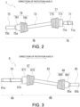
- FIG. 2 is a diagram showing the drive shaft 7.
- the drive shaft 7 includes a differential-side shaft member 71, an intermediate shaft member 73, and a drive wheel-side shaft member 75.
- the differential-side shaft member 71 is located inside the case 10 as a first region 7A of the drive shaft 7.
- the intermediate shaft member 73 and the drive wheel-side shaft member 75 are positioned outside the case 10.
- the drive wheel-side shaft member 75 is connected to the drive wheel KA in manner of being capable of transmitting rotation thereto.
- the intermediate shaft member 73 is provided between the differential-side shaft member 71 and the drive wheel-side shaft member 75.
- the intermediate shaft member 73 is connected to the differential-side shaft member 71 and the drive wheel-side shaft member 75 via universal joints 77 and 78 in manner of being capable of transmitting rotation.
- the intermediate shaft member 73, the drive wheel-side shaft member 75, and the universal joints 77, 78 are positioned outside the case 10 as a second region 7B of the drive shaft 7.
- the differential-side shaft member 71 is disposed coaxially with the rotation axis X of the motor 2 inside the case 10.
- One end 71a of the differential-side shaft member 71 is connected to the differential mechanism 5 from one side in the direction of the rotation axis X (left side in the figure).
- An opening 11a is provided at an end portion 11 of the case 10 in the direction of the rotation axis X.
- the other end 71b of the differential-side shaft member 71 in the direction of the rotation axis X passes through the opening 11a and is connected to the universal joint 77 located near the opening 11a.
- One end 73a of the intermediate shaft member 73 in the direction of the rotation axis X is connected to the universal joint 77 from an opposite side of the differential-side shaft member 71.
- the other end 73b of the intermediate shaft member 73 in the direction of the rotation axis X is connected to the universal joint 78.
- One end 75a of the drive wheel-side shaft member 75 in the direction of the rotation axis X is connected to the universal joint 78 from an opposite side of the intermediate shaft member 73.
- the other end 75b of the drive wheel-side shaft member 75 in the direction of the rotation axis X is connected to the drive wheel KA.
- the universal joint 77 includes a joint member 771 that is coupled to the intermediate shaft member 73, and a boot 775 that covers a coupling portion (not shown) of the joint member 771 and the intermediate shaft member 73.
- the intermediate shaft member 73 is swingably coupled to an inside of the joint member 771.
- the boot 775 prevents leakage of a lubricant enclosed in the joint member 771 and prevents a foreign matter from entering from an outside.
- the universal joint 78 includes a joint member 781 coupled to the intermediate shaft member 73, and a boot 785 that covers a coupling portion between the joint member 781 and the intermediate shaft member 73.
- the intermediate shaft member 73 is swingably coupled to an inside of the joint member 781.
- the boot 785 prevents leakage of the lubricant enclosed in the joint member 781 and prevents a foreign matter from entering from an outside.
- FIG. 3 is a diagram showing the drive shaft 8.
- the drive shaft 8 includes a differential-side shaft member 81, an intermediate shaft member 83, and a drive wheel-side shaft member 85.
- the differential-side shaft member 81 is located inside the case 10 as a first region 8A of the drive shaft 8.
- the intermediate shaft member 83 and the drive wheel-side shaft member 85 are positioned outside the case 10.
- the drive wheel-side shaft member 85 is connected to the drive wheel KB.
- the intermediate shaft member 83 is provided between the differential-side shaft member 81 and the drive wheel-side shaft member 85.
- the intermediate shaft member 83 is connected to the differential-side shaft member 81 and the drive wheel-side shaft member 85 via universal joints 87, 88, respectively.
- the intermediate shaft member 83, the drive wheel-side shaft member 85, and the universal joints 87, 88 are positioned outside the case 10 as a second region 8B of the drive shaft 8.
- the differential-side shaft member 81 is disposed coaxially with the rotation axis X of the motor 2 inside the case 10.
- One end 81a of the differential-side shaft member 81 in the direction of the rotation axis X is connected to the differential mechanism 5 from the other side (right side in the figure) in the direction of the rotation axis X.
- the differential-side shaft member 81 is inserted through an inner periphery of the motor shaft 21 inside the case 10.
- An opening 12a is provided at an end portion 12 of the case 10 on the other side in the direction of the rotation axis X.
- the other end 81b of the differential-side shaft member 81 in the direction of the rotation axis X passes through the opening 12a and is connected to the universal joint 87 located near the opening 12a.
- One end 83a of the intermediate shaft member 83 in the direction of the rotation axis X is connected to the universal joint 87 from an opposite side of the differential-side shaft member 81.
- the other end 83b of the intermediate shaft member 83 in the direction of the rotation axis X is connected to the universal joint 88.
- One end 85a of the drive wheel-side shaft member 85 in the direction of the rotation axis X is connected to the universal joint 88 from an opposite side of the intermediate shaft member 83.
- the other end 85b of the drive wheel-side shaft member 85 in the direction of the rotation axis X is connected to the drive wheel KB.
- the universal joint 87 includes a joint member 871 that is coupled to the intermediate shaft member 83, and a boot 875 that covers a coupling portion between the joint member 871 and the intermediate shaft member 83.
- the intermediate shaft member 83 is swingably coupled to an inside of the joint member 871.
- the boot 875 prevents leakage of the lubricant enclosed in the joint member 871 and prevents a foreign matter from entering from an outside.
- the universal joint 88 includes a joint member 881 that is coupled to the intermediate shaft member 83, and a boot 885 that covers a coupling portion of the joint member 881 and the intermediate shaft member 83.
- the intermediate shaft member 83 is swingably coupled to an inside of the joint member 881.
- the boot 885 prevents leakage of the lubricant enclosed in the joint member 881 and prevents a foreign matter from entering from an outside.
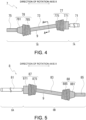
- FIG. 4 is a diagram showing the drive shaft 7 provided with a noise reduction sheet.
- FIG. 5 is a diagram showing the drive shaft 8 provided with a noise reduction sheet.
- FIG. 6 is a cross-sectional view taken along a line A-A in FIG. 4 .
- a noise reduction sheet 9 is shown by cross-hatching for ease of understanding. Further, in FIG. 6 , thicknesses of the noise reduction sheet 9 and an adhesive AH are exaggerated for easy understanding.
- each of the drive shafts 7, 8 includes a portion that is covered with the noise reduction sheet 9 (noise reducing material).
- the drive shafts 7, 8 respectively have portions that overlap with the noise reduction sheet 9 when viewed in radial directions of the respective axes.
- the second region 7B of the drive shaft 7 is covered with the noise reduction sheet 9.
- surfaces of the intermediate shaft member 73, the drive wheel-side shaft member 75, and the universal joints 77, 78 are covered with the noise reduction sheet 9.
- the second region 8B of the drive shaft 8 is covered with the noise reduction sheet 9.
- surfaces of the intermediate shaft member 83, the drive wheel-side shaft member 85, and the universal joints 87, 88 are covered with the noise reduction sheet 9.
- the second regions 7B, 8B of the drive shafts 7, 8 are regions located outside the case 10 (see FIG. 1 ).
- the noise reduction sheet 9 has a characteristic of converting high-frequency noise into heat.
- the noise reduction sheet 9 is provided to reduce the noise.
- the noise reduction sheet 9 is, for example, a resin film or a film containing a magnetic material, a conductive material, or the like.
- the conductive material include metals, carbon, and graphite.
- the noise reduction sheet 9 may be obtained by coating a fiber such as a woven fabric, a knitted fabric, or a nonwoven fabric with a conductive material, or may be a sheet in which a magnetic material or a conductive material is supported on the above-described various fibers.
- the noise reduction sheet 9 is attached so as to cover a surface of the drive shaft 7.
- the noise reduction sheet 9 can be attached closely to the surface of the drive shaft 7 using, for example, the adhesive AH.
- FIG. 6 illustrates the intermediate shaft member 73
- the noise reduction sheet 9 can be attached to the drive wheel-side shaft member 75 and the universal joints 77 and 78 using the adhesive AH.
- the noise reduction sheet 9 can be attached to the drive shaft 8 by using the adhesive AH.
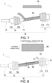
- FIG. 7 is a diagram showing an example of the attachment of the noise reduction sheet.
- FIG. 8 is a diagram showing another example of the attachment of the noise reduction sheet.
- FIGS. 7 and 8 show only the second region 7B of the drive shaft 7, and illustration of the adhesive is omitted.
- FIGS. 7 and 8 illustrate an example in which the noise reduction sheet 9 is attached to the intermediate shaft member 73 of the drive shaft 7, but the noise reduction sheet 9 can also be attached to other locations in the same manner. Similarly, the noise reduction sheet 9 can be attached to the drive shaft 8 in the same manner.
- the noise reduction sheets 9 are also referred to as a noise reduction sheet 9A and a noise reduction sheet 9B as necessary.
- the noise reduction sheet 9A may have a strip shape, for example.
- the strip-shaped noise reduction sheet 9A may be wound in a spiral shape, for example, around a surface of the intermediate shaft member 73 with phases shifted from one another.
- FIG. 7 shows an example in which the noise reduction sheet 9A is attached to the intermediate shaft member 73, but the strip-shaped noise reduction sheet 9A can also be wound around the universal joints 77, 78, for example. Accordingly, the noise reduction sheet 9A can be attached closely to the universal joints 77, 78 which have many projections and recesses on surfaces thereof.
- the noise reduction sheet 9B may have a rectangular shape, for example.
- the rectangular-shaped noise reduction sheet 9B can be attached to the surface of the intermediate shaft member 73 with a longitudinal direction aligned with a direction of an axis X1 of the intermediate shaft member 73 and one end 91 and the other end 92 in a lateral direction abutting against each other.
- the noise reduction sheet 9B may be attached such that the other end 92 overlaps with the one end 91.
- the intermediate shaft member 73 has relatively few projections and recesses and a long axial length. Accordingly, by using the noise reduction sheet 9B having the rectangular shape, the noise reduction sheet 9B can be efficiently attached. Similarly, the rectangular-shaped noise reduction sheet 9B can be attached efficiently to the drive wheel-side shaft member 75 as well.
- the shape of the noise reduction sheet 9 and a portion to which the noise reduction sheet 9 is attached are not limited to the examples in FIGS. 7 and 8 .
- the shape of the noise reduction sheet 9 and the portion to which the noise reduction sheet 9 is attached can be appropriately changed.
- FIG. 9 is a diagram illustrating propagation of the noise in the power transmission device 1.
- the noise is indicated by a hatched arrow.
- the inverter 6 includes a transistor that is a switch element.
- ringing which is a high-frequency noise, occurs.
- This noise is propagated from the inverter 6, which is a source of the noise, to a power transmission path of the motor 2. That is, the noise is finally propagated to the drive shafts 7, 8 via the motor 2, the motor shaft 21, the planetary reduction gear 4, and the differential mechanism 5.
- the drive shafts 7, 8 operate as antennas. Therefore, the noise propagated to the drive shafts 7, 8 is emitted to air from the drive shafts 7, 8.
- the noise emitted to the air may affect vehicle equipment such as an AM radio and radio communication device mounted on the vehicle.
- vehicle equipment such as an AM radio and radio communication device mounted on the vehicle.
- the second regions 7B, 8B (see FIGS. 2 and 3 ) of the drive shafts 7, 8 are located outside the case 10, there is a high possibility that the emitted noise affects the vehicle equipment.
- the vehicle equipment is, for example, an electronic device provided in the vehicle in which the power transmission device 1 is mounted.
- ground connector on the power transmission path of the motor 2.
- the ground connector is, for example, a sliding brush that comes into sliding contact with shaft elements (motor shaft 21, drive shafts 7, 8, and the like) on the power transmission path.
- the ground connector is connected to the case 10, and the case 10 is connected to a vehicle body by a ground line. Since the power transmission path is grounded to the vehicle body via the ground connector and the case 10, the noise can be reduced from being emitted from the drive shafts 7, 8.
- the ground connector is preferably provided at a position away from the inverter 6 which is the source of the noise.
- the second regions 7B, 8B of the drive shafts 7, 8 are separated from the inverter 6, the intermediate shaft members 73, 83 and the drive wheel-side shaft members 75, 85 swing. Therefore, it is difficult to provide the ground connector, which is the sliding brush, so as to be in normal contact with these members. Further, it is necessary to provide the ground connector in a dry environment, but the second regions 7B, 8B located outside the case 10 may be exposed to muddy water and the like, and thus when the ground connector is provided in the second regions 7B, 8B, it is difficult to place the ground connector in the dry environment.
- the ground connector When the ground connector is provided inside the case 10, the ground connector is a thick member, and the layout in the case 10 is easily restricted. Further, oil for lubrication of a rotary member is stored in the case 10. In order to provide the ground connector in the dry environment, it is necessary to provide, in the case 10, a separate chamber sealed to prevent the oil from entering. However, providing the separate chamber in the case 10 may lead to an increase in size of the case 10. Furthermore, since it is necessary to bring the ground connector into contact with a metal portion, there is a possibility that a dimension of the motor shaft 21 or the differential-side shaft member 71 is enlarged. In this way, a layout of the ground connector is likely to be restricted, and this may lead to an increase in size of the power transmission device 1.
- the noise reduction sheet 9 is a member having a small thickness, and can be provided in close contact with surfaces of the drive shafts 7, 8. Therefore, the noise reduction sheet 9 has few layout restrictions and is unlikely to lead to the increase in size of the power transmission device 1. Since it is not necessary to provide the noise reduction sheet 9 in the dry environment, the noise reduction sheet 9 can be provided in the second regions 7B, 8B of the drive shafts 7, 8 located outside the case 10. Since the noise reduction sheet 9 can be attached with the adhesive AH, the noise reduction sheet 9 can also be provided on the intermediate shaft member 73 and the drive wheel-side shaft member 75 that swing.
- the drive shafts 7, 8 act as the antennas and emit the noise, thereby affecting the vehicle equipment. Further, since the second regions 7B, 8B of the drive shafts 7, 8 are exposed to an outside of the case 10, the noise emitted from the second regions 7B, 8B easily affects the vehicle equipment. By providing the noise reduction sheet 9 in manner of covering the second regions 7B, 8B, it is possible to reduce the noise that easily affects the vehicle equipment.
- the drive shafts 7, 8 respectively have portions (second region 7B and second region 8B) covered with the noise reduction sheet 9 (noise reducing material).
- the power transmission device 1 includes the motor 2, the gear device, the drive shafts 7, 8, and the drive wheels KA, KB provided along the power transmission path.
- the motor 2 is driven by the inverter 6.
- the power (rotation force) generated by the motor 2 is transmitted to the drive wheels KA, KB via the gear device and the drive shafts 7, 8.
- the high-frequency noise generated by the inverter 6 is propagated to the drive shafts 7, 8 along the power transmission path of the motor 2.
- the propagated noise is finally emitted from the drive shafts 7, 8 acting as the antennas.
- the noise emitted from the drive shafts 7, 8 may affect the vehicle equipment such as an AM radio.
- the noise reducing material As the sheet-shaped noise reduction sheet 9, the noise reducing material can be easily attached in manner of being wound around the drive shafts 7, 8. Further, the noise reduction sheet 9 requires little space for installation, and therefore the increase in size of the device can be reduced. Furthermore, since the noise reduction sheet 9 is not subject to many restrictions regarding an installation environment, such as a dry environment, and therefore allows for greater freedom in layout.
- a drive shaft of the power transmission device 1 includes the drive shaft 7 (first drive shaft) and the drive shaft 8 (second drive shaft).
- the noise reduction sheet 9 is preferably provided on both the drive shaft 7 and the drive shaft 8.
- the power transmission device 1 includes the two drive shafts 7, 8 in order to transmit the power to each of the left and right drive wheels KA, KB.
- the two drive shafts 7 and 8 act as the antennas to emit the noise. Therefore, by providing the noise reduction sheet 9 on at least one of the two drive shafts 7, 8, and preferably on both, a noise reducing effect (effect of reducing the emitted noise) can be improved.
- the power transmission device 1 includes the case 10 that accommodates the planetary reduction gear 4 and the differential mechanism 5 (gear device).
- the drive shafts 7, 8 respectively have the first regions 7A, 8A connected to the differential mechanism 5 of the gear device inside the case 10.
- the first regions 7A, 8A respectively include the differential-side shaft members 71, 81.
- the drive shafts 7, 8 respectively have the second regions 7B, 8B connected to the drive wheels KA, KB outside the case 10.
- the second region 7B includes the intermediate shaft member 73, the drive wheel-side shaft member 75, and the universal joints 77, 78.
- the second region 8B includes the intermediate shaft member 83, the drive wheel-side shaft member 85, and the universal joints 87, 88.
- the portion covered with the noise reduction sheet 9 can be provided in each of the second regions 7B, 8B of the drive shafts 7, 8.
- the noise propagated to the drive shafts 7, 8 is easily emitted to an outside of the power transmission device 1 from the portions of the second regions 7B, 8B exposed to the outside.
- the noise reduction sheet 9 in the second regions 7B, 8B the noise reducing effect can be improved.
- the second regions 7B, 8B of the drive shafts 7, 8 are located outside the case 10, and thus may be exposed to muddy water or the like.
- the noise reduction sheet 9 is not required to be used in the dry environment. Therefore, even if the noise reduction sheet 9 is provided in the second regions 7B, 8B which are not always under the dry environment, the noise reducing effect can be exhibited.
- the noise reduction sheet 9 has a sheet shape, the noise reduction sheet 9 can be provided in manner of being wound around the surfaces of the drive shafts 7 and 8. Therefore, for example, the intermediate shaft members 73, 83 of the second regions 7B, 8B are members that swing when the vehicle is traveling, and the noise reduction sheet 9 can also be provided on such swing members, that is, the intermediate shaft members 73, 83 and connecting members with these intermediate shaft members 73, 83.
- the noise reduction sheet 9 has a high degree of freedom in terms of installation, and can be easily provided in any location where it is desired to exert the noise reducing effect.
- a portion of the second regions 7B, 8B may be provided with a portion that is covered with the noise reduction sheet 9.
- the noise reduction sheet 9 is preferably provided in close contact with the drive shafts 7 and 8.
- the noise reduction effect may be affected.
- the noise reduction sheet 9 By bringing the noise reduction sheet 9 into close contact with the surfaces of the drive shafts 7 and 8, it is possible to more effectively reduce the noise.
- the noise reduction sheet 9 can be attached to the drive shafts 7 and 8 by, for example, an adhesive AH.
- the noise reduction sheet 9 can be easily brought into close contact with the drive shafts 7 and 8.
- the noise reducing material is not limited to a sheet-shaped material.
- the noise reducing material may be, for example, a powdered magnetic material, a conductive material, or the like, which is directly applied or sprayed onto the surfaces of the drive shafts 7, 8.
- the example in which the noise reduction sheet 9 is attached to the drive shafts 7 and 8 using the adhesive AH has been described.
- An installation mode of the noise reduction sheet 9 is not limited to this mode.
- the noise reduction sheet 9 may be applied to the drive shafts 7 and 8 using, for example, a double-sided tape.
- the noise reduction sheet 9 may be in close contact with the surfaces of the drive shafts 7, 8 by a method such as vapor deposition.
- noise reduction sheet 9 is provided in the second regions 7B, 8B of the drive shafts 7, 8.
- An installation location of the noise reduction sheet 9 is not limited to this aspect.
- the noise reduction sheet 9 can also be provided in the first regions 7A, 8A of the drive shafts 7, 8.
- the present invention is not limited to this aspect and the device can be applied to other devices besides the vehicle.
- the present invention is not limited to this aspect and the device can be applied to other devices besides the vehicle.
Landscapes
- Engineering & Computer Science (AREA)
- General Engineering & Computer Science (AREA)
- Mechanical Engineering (AREA)
- Chemical & Material Sciences (AREA)
- Combustion & Propulsion (AREA)
- Transportation (AREA)
- Ocean & Marine Engineering (AREA)
- Physics & Mathematics (AREA)
- Acoustics & Sound (AREA)
- Aviation & Aerospace Engineering (AREA)
- Power Engineering (AREA)
- Motor Power Transmission Devices (AREA)
Abstract
Description
- The present invention relates to a device.
- Patent Document 1 discloses a device including a motor and an inverter that drives the motor. A gear device is connected downstream of the motor. A drive shaft is connected downstream of the gear device. Power (rotation force) generated by the motor is transmitted to drive wheels via the gear device and the drive shaft.
- Patent Document 1:
JP 2014-147293 A - High frequency noise is generated when a transistor of the inverter repeatedly turns on and off at a high speed. The noise is propagated from the inverter, which is a source of the noise, to a power transmission path of the motor. The noise is finally emitted from the drive shaft, which acts as an antenna. The emitted noise can affect peripheral devices such as radios.
- In the device, there is a demand for reducing the noise emitted from the drive shaft.
- A device according to an aspect of the present invention includes:
- a motor;
- an inverter configured to drive the motor;
- a gear device connected downstream of the motor; and
- a drive shaft configured to transmit, to a drive wheel, power of the motor transmitted from the gear device, in which
- the drive shaft includes a portion covered with a noise reducing material.
- According to an aspect of the present invention, noise emitted from a drive shaft can be reduced.
-
- [
FIG. 1] FIG. 1 is a skeleton diagram showing a power transmission device. - [
FIG. 2] FIG. 2 is a diagram showing adrive shaft 7. - [
FIG. 3] FIG. 3 is a diagram showing adrive shaft 8. - [
FIG. 4] FIG. 4 is a diagram showing thedrive shaft 7 provided with a noise reduction sheet. - [
FIG. 5] FIG. 5 is a diagram showing thedrive shaft 8 provided with a noise reduction sheet. - [
FIG. 6] FIG. 6 is a cross-sectional view taken along a line A-A inFIG. 4 . - [
FIG. 7] FIG. 7 is a diagram showing an example of attachment of the noise reduction sheet. - [
FIG. 8] FIG. 8 is a diagram showing another example of the attachment of the noise reduction sheet. - [
FIG. 9] FIG. 9 is a diagram illustrating propagation of noise in the power transmission device. - In the following description, a power transmission device mounted on a vehicle is described as an example of a device according to an aspect of the present invention. The power transmission device includes a motor that is a rotation electrical machine, and a power transmission mechanism that transmits power of the motor to a drive wheel. The power transmission mechanism includes, for example, a gear mechanism and/or a differential gear mechanism.
- In the following description, when referring to a second element (member, portion, or the like) connected to a first element (member, portion, or the like), a second element (member, portion, or the like) connected downstream of a first element (member, portion, or the like), or a second element (member, portion, or the like) connected upstream of a first element (member, portion, or the like), it is meant that the first element and the second element are connected to each other in a power-transmissible manner. A power input side is upstream, and a power output side is downstream. Further, the first element and the second element may be connected to each other via another element (clutch, other gear mechanism, or the like).
- "Overlapping when viewed from a predetermined direction" means that a plurality of elements are arranged in a predetermined direction, and has the same meaning as "overlapping in a predetermined direction". The "predetermined direction" is, for example, an axial direction, a radial direction, a gravity direction, or a vehicle traveling direction (vehicle forward direction and vehicle backward direction).
- If a drawing shows that a plurality of elements (member, portion, or the like) are arranged in a predetermined direction, it can be considered that in explanation of the description, there is a sentence illustrating that the plurality of elements overlap when viewed from the predetermined direction.
- "Not overlapping when viewed from a predetermined direction" and "offset when viewed from a predetermined direction" mean that a plurality of elements are not arranged in a predetermined direction, and has the same meaning as "not overlapping in a predetermined direction" and "offset in a predetermined direction". The "predetermined direction" is, for example, an axial direction, a radial direction, a gravity direction, or a vehicle traveling direction (vehicle forward direction and vehicle backward direction).
- If a drawing shows that a plurality of elements (member, portion, or the like) are not arranged in a predetermined direction, it can be considered that in explanation of the description, there is a sentence illustrating that the plurality of elements do not overlap when viewed from the predetermined direction.
- "When viewed from a predetermined direction, a first element (member, portion, or the like) is positioned between a second element (member, portion, or the like) and a third element (member, portion, or the like)" means that the first element can be observed to be between the second element and the third element when viewed from the predetermined direction. The "predetermined direction" is, for example, an axial direction, a radial direction, a gravity direction, or a vehicle traveling direction (vehicle forward direction and vehicle backward direction).
- For example, when the second element, the first element, and the third element are arranged in this order along the axial direction, it can be said that the first element is positioned between the second element and the third element when viewed from the radial direction. If a drawing shows that a first element is between a second element and a third element when viewed from a predetermined direction, it can be considered that in explanation of the description, there is a sentence illustrating that the first element is between the second element and the third element when viewed from the predetermined direction.
- In the following description, the "axial direction" means an axial direction of a rotation axis of a member that constitutes the device. The "radial direction" means a direction orthogonal to the rotation axis of the member that constitutes the device. A "circumferential direction" refers to a circumferential direction about the rotation axis of the member that constitutes the device.
-
FIG. 1 is a skeleton diagram illustrating a power transmission device 1. - As shown in
FIG. 1 , the power transmission device 1 includes amotor 2, a power transmission mechanism 3, and aninverter 6. Themotor 2 is driven by theinverter 6. Power generated by rotation of themotor 2 about a rotation axis X is transmitted to drive wheels KA and KB of a vehicle via the power transmission mechanism 3. Themotor 2 is a rotation electrical machine having at least one of an electric motor function and a generator function. - The power transmission mechanism 3 includes a gear device including a
planetary reduction gear 4 and adifferential mechanism 5, and driveshafts planetary reduction gear 4 is connected downstream of themotor 2. Thedifferential mechanism 5 is connected downstream of themotor 2 via theplanetary reduction gear 4. Thedifferential mechanism 5 is disposed coaxially with the rotation axis X. Thedrive shafts differential mechanism 5. - In the power transmission device 1, the
planetary reduction gear 4, thedifferential mechanism 5, and thedrive shafts motor 2. - The output rotation of the
motor 2 is transmitted to theplanetary reduction gear 4 via amotor shaft 21. Theplanetary reduction gear 4 reduces the transmitted rotation and outputs the reduced rotation to thedifferential mechanism 5. Thedrive shafts differential mechanism 5, respectively. Thedifferential mechanism 5 outputs the rotation input from aplanetary reduction gear 4 side to thedrive shafts - As shown in
FIG. 1 , themotor 2 and the gear device (planetary reduction gear 4 and differential mechanism 5) are accommodated in acase 10. - Although not shown, the
case 10 may include a partition wall between themotor 2 and the gear device (planetary reduction gear 4 and differential mechanism 5). Themotor 2 and the gear device (planetary reduction gear 4 and differential mechanism 5) may be accommodated in separate cases, and the cases may be joined together to form thecase 10. - The
drive shafts differential mechanism 5 inside thecase 10. Thedrive shafts case 10. The output rotation of themotor 2 is finally transmitted to the drive wheels KA, KB via thedrive shafts - The
inverter 6 is an electronic component including a smoothing capacitor, a transistor, a driver board, and the like (not shown). Theinverter 6 is electrically connected to themotor 2 in thecase 10. Theinverter 6 converts a direct current into an alternating current and supplies the alternating current to themotor 2 to drive themotor 2. Theinverter 6 controls a rotation speed of themotor 2 by changing a frequency of the alternating current. -
FIG. 2 is a diagram showing thedrive shaft 7. - As shown in
FIGS. 1 and2 , thedrive shaft 7 includes a differential-side shaft member 71, anintermediate shaft member 73, and a drive wheel-side shaft member 75. - The differential-
side shaft member 71 is located inside thecase 10 as afirst region 7A of thedrive shaft 7. - The
intermediate shaft member 73 and the drive wheel-side shaft member 75 are positioned outside thecase 10. - The drive wheel-
side shaft member 75 is connected to the drive wheel KA in manner of being capable of transmitting rotation thereto. Theintermediate shaft member 73 is provided between the differential-side shaft member 71 and the drive wheel-side shaft member 75. Theintermediate shaft member 73 is connected to the differential-side shaft member 71 and the drive wheel-side shaft member 75 viauniversal joints - The
intermediate shaft member 73, the drive wheel-side shaft member 75, and theuniversal joints case 10 as asecond region 7B of thedrive shaft 7. - As shown in
FIG. 1 , the differential-side shaft member 71 is disposed coaxially with the rotation axis X of themotor 2 inside thecase 10. Oneend 71a of the differential-side shaft member 71 is connected to thedifferential mechanism 5 from one side in the direction of the rotation axis X (left side in the figure). Anopening 11a is provided at anend portion 11 of thecase 10 in the direction of the rotation axis X. Theother end 71b of the differential-side shaft member 71 in the direction of the rotation axis X passes through theopening 11a and is connected to the universal joint 77 located near theopening 11a. - One
end 73a of theintermediate shaft member 73 in the direction of the rotation axis X is connected to the universal joint 77 from an opposite side of the differential-side shaft member 71. Theother end 73b of theintermediate shaft member 73 in the direction of the rotation axis X is connected to theuniversal joint 78. - One
end 75a of the drive wheel-side shaft member 75 in the direction of the rotation axis X is connected to the universal joint 78 from an opposite side of theintermediate shaft member 73. Theother end 75b of the drive wheel-side shaft member 75 in the direction of the rotation axis X is connected to the drive wheel KA. - As shown in
FIG. 2 , theuniversal joint 77 includes ajoint member 771 that is coupled to theintermediate shaft member 73, and aboot 775 that covers a coupling portion (not shown) of thejoint member 771 and theintermediate shaft member 73. Although not shown, theintermediate shaft member 73 is swingably coupled to an inside of thejoint member 771. Theboot 775 prevents leakage of a lubricant enclosed in thejoint member 771 and prevents a foreign matter from entering from an outside. - The
universal joint 78 includes ajoint member 781 coupled to theintermediate shaft member 73, and aboot 785 that covers a coupling portion between thejoint member 781 and theintermediate shaft member 73. Although not shown, theintermediate shaft member 73 is swingably coupled to an inside of thejoint member 781. Theboot 785 prevents leakage of the lubricant enclosed in thejoint member 781 and prevents a foreign matter from entering from an outside. -
FIG. 3 is a diagram showing thedrive shaft 8. - As shown in
FIGS. 1 and3 , thedrive shaft 8 includes a differential-side shaft member 81, anintermediate shaft member 83, and a drive wheel-side shaft member 85. - As shown in
FIG. 1 , the differential-side shaft member 81 is located inside thecase 10 as afirst region 8A of thedrive shaft 8. - The
intermediate shaft member 83 and the drive wheel-side shaft member 85 are positioned outside thecase 10. - The drive wheel-
side shaft member 85 is connected to the drive wheel KB. Theintermediate shaft member 83 is provided between the differential-side shaft member 81 and the drive wheel-side shaft member 85. Theintermediate shaft member 83 is connected to the differential-side shaft member 81 and the drive wheel-side shaft member 85 viauniversal joints - The
intermediate shaft member 83, the drive wheel-side shaft member 85, and theuniversal joints case 10 as asecond region 8B of thedrive shaft 8. - As shown in
FIG. 1 , the differential-side shaft member 81 is disposed coaxially with the rotation axis X of themotor 2 inside thecase 10. Oneend 81a of the differential-side shaft member 81 in the direction of the rotation axis X is connected to thedifferential mechanism 5 from the other side (right side in the figure) in the direction of the rotation axis X. The differential-side shaft member 81 is inserted through an inner periphery of themotor shaft 21 inside thecase 10. Anopening 12a is provided at anend portion 12 of thecase 10 on the other side in the direction of the rotation axis X. Theother end 81b of the differential-side shaft member 81 in the direction of the rotation axis X passes through theopening 12a and is connected to the universal joint 87 located near theopening 12a. - One
end 83a of theintermediate shaft member 83 in the direction of the rotation axis X is connected to the universal joint 87 from an opposite side of the differential-side shaft member 81. Theother end 83b of theintermediate shaft member 83 in the direction of the rotation axis X is connected to theuniversal joint 88. - One
end 85a of the drive wheel-side shaft member 85 in the direction of the rotation axis X is connected to the universal joint 88 from an opposite side of theintermediate shaft member 83. Theother end 85b of the drive wheel-side shaft member 85 in the direction of the rotation axis X is connected to the drive wheel KB. - As shown in
FIG. 3 , theuniversal joint 87 includes ajoint member 871 that is coupled to theintermediate shaft member 83, and aboot 875 that covers a coupling portion between thejoint member 871 and theintermediate shaft member 83. Although not shown, theintermediate shaft member 83 is swingably coupled to an inside of thejoint member 871. Theboot 875 prevents leakage of the lubricant enclosed in thejoint member 871 and prevents a foreign matter from entering from an outside. - The
universal joint 88 includes ajoint member 881 that is coupled to theintermediate shaft member 83, and aboot 885 that covers a coupling portion of thejoint member 881 and theintermediate shaft member 83. Although not shown, theintermediate shaft member 83 is swingably coupled to an inside of thejoint member 881. Theboot 885 prevents leakage of the lubricant enclosed in thejoint member 881 and prevents a foreign matter from entering from an outside. -
FIG. 4 is a diagram showing thedrive shaft 7 provided with a noise reduction sheet. -
FIG. 5 is a diagram showing thedrive shaft 8 provided with a noise reduction sheet. -
FIG. 6 is a cross-sectional view taken along a line A-A inFIG. 4 . - In
FIGS. 4 to 6 , anoise reduction sheet 9 is shown by cross-hatching for ease of understanding. Further, inFIG. 6 , thicknesses of thenoise reduction sheet 9 and an adhesive AH are exaggerated for easy understanding. - As shown in
FIGS. 4 and 5 , each of thedrive shafts drive shafts noise reduction sheet 9 when viewed in radial directions of the respective axes. - As shown in
FIG. 4 , thesecond region 7B of thedrive shaft 7 is covered with thenoise reduction sheet 9. Specifically, surfaces of theintermediate shaft member 73, the drive wheel-side shaft member 75, and theuniversal joints noise reduction sheet 9. - As shown in
FIG. 5 , similarly, thesecond region 8B of thedrive shaft 8 is covered with thenoise reduction sheet 9. Specifically, surfaces of theintermediate shaft member 83, the drive wheel-side shaft member 85, and theuniversal joints noise reduction sheet 9. - As described above, the
second regions drive shafts FIG. 1 ). - The
noise reduction sheet 9 has a characteristic of converting high-frequency noise into heat. Thenoise reduction sheet 9 is provided to reduce the noise. - The
noise reduction sheet 9 is, for example, a resin film or a film containing a magnetic material, a conductive material, or the like. Examples of the conductive material include metals, carbon, and graphite. Thenoise reduction sheet 9 may be obtained by coating a fiber such as a woven fabric, a knitted fabric, or a nonwoven fabric with a conductive material, or may be a sheet in which a magnetic material or a conductive material is supported on the above-described various fibers. - As shown in
FIG. 6 , thenoise reduction sheet 9 is attached so as to cover a surface of thedrive shaft 7. Thenoise reduction sheet 9 can be attached closely to the surface of thedrive shaft 7 using, for example, the adhesive AH. - Although
FIG. 6 illustrates theintermediate shaft member 73, similarly, thenoise reduction sheet 9 can be attached to the drive wheel-side shaft member 75 and theuniversal joints noise reduction sheet 9 can be attached to thedrive shaft 8 by using the adhesive AH. -
FIG. 7 is a diagram showing an example of the attachment of the noise reduction sheet. -
FIG. 8 is a diagram showing another example of the attachment of the noise reduction sheet. -
FIGS. 7 and 8 show only thesecond region 7B of thedrive shaft 7, and illustration of the adhesive is omitted.FIGS. 7 and 8 illustrate an example in which thenoise reduction sheet 9 is attached to theintermediate shaft member 73 of thedrive shaft 7, but thenoise reduction sheet 9 can also be attached to other locations in the same manner. Similarly, thenoise reduction sheet 9 can be attached to thedrive shaft 8 in the same manner. - In the following description, the
noise reduction sheets 9 are also referred to as anoise reduction sheet 9A and anoise reduction sheet 9B as necessary. - As shown in
FIG. 7 , thenoise reduction sheet 9A may have a strip shape, for example. The strip-shapednoise reduction sheet 9A may be wound in a spiral shape, for example, around a surface of theintermediate shaft member 73 with phases shifted from one another.FIG. 7 shows an example in which thenoise reduction sheet 9A is attached to theintermediate shaft member 73, but the strip-shapednoise reduction sheet 9A can also be wound around theuniversal joints noise reduction sheet 9A can be attached closely to theuniversal joints - As shown in
FIG. 8 , thenoise reduction sheet 9B may have a rectangular shape, for example. The rectangular-shapednoise reduction sheet 9B can be attached to the surface of theintermediate shaft member 73 with a longitudinal direction aligned with a direction of an axis X1 of theintermediate shaft member 73 and oneend 91 and theother end 92 in a lateral direction abutting against each other. Alternatively, thenoise reduction sheet 9B may be attached such that theother end 92 overlaps with the oneend 91. - The
intermediate shaft member 73 has relatively few projections and recesses and a long axial length. Accordingly, by using thenoise reduction sheet 9B having the rectangular shape, thenoise reduction sheet 9B can be efficiently attached. Similarly, the rectangular-shapednoise reduction sheet 9B can be attached efficiently to the drive wheel-side shaft member 75 as well. - The shape of the
noise reduction sheet 9 and a portion to which thenoise reduction sheet 9 is attached are not limited to the examples inFIGS. 7 and 8 . The shape of thenoise reduction sheet 9 and the portion to which thenoise reduction sheet 9 is attached can be appropriately changed. -
FIG. 9 is a diagram illustrating propagation of the noise in the power transmission device 1. InFIG. 9 , the noise is indicated by a hatched arrow. - As described above, the
inverter 6 includes a transistor that is a switch element. When the transistor is repeatedly turned on and off at a high speed during control of themotor 2, ringing, which is a high-frequency noise, occurs. This noise is propagated from theinverter 6, which is a source of the noise, to a power transmission path of themotor 2. That is, the noise is finally propagated to thedrive shafts motor 2, themotor shaft 21, theplanetary reduction gear 4, and thedifferential mechanism 5. - The
drive shafts drive shafts drive shafts second regions FIGS. 2 and 3 ) of thedrive shafts case 10, there is a high possibility that the emitted noise affects the vehicle equipment. Here, the vehicle equipment is, for example, an electronic device provided in the vehicle in which the power transmission device 1 is mounted. - In order to reduce the emitted noise, for example, it is conceivable to provide a ground connector on the power transmission path of the
motor 2. The ground connector is, for example, a sliding brush that comes into sliding contact with shaft elements (motor shaft 21,drive shafts case 10, and thecase 10 is connected to a vehicle body by a ground line. Since the power transmission path is grounded to the vehicle body via the ground connector and thecase 10, the noise can be reduced from being emitted from thedrive shafts - The ground connector is preferably provided at a position away from the
inverter 6 which is the source of the noise. Although thesecond regions drive shafts inverter 6, theintermediate shaft members side shaft members second regions case 10 may be exposed to muddy water and the like, and thus when the ground connector is provided in thesecond regions - When the ground connector is provided inside the
case 10, the ground connector is a thick member, and the layout in thecase 10 is easily restricted. Further, oil for lubrication of a rotary member is stored in thecase 10. In order to provide the ground connector in the dry environment, it is necessary to provide, in thecase 10, a separate chamber sealed to prevent the oil from entering. However, providing the separate chamber in thecase 10 may lead to an increase in size of thecase 10. Furthermore, since it is necessary to bring the ground connector into contact with a metal portion, there is a possibility that a dimension of themotor shaft 21 or the differential-side shaft member 71 is enlarged. In this way, a layout of the ground connector is likely to be restricted, and this may lead to an increase in size of the power transmission device 1. - On the other hand, the
noise reduction sheet 9 is a member having a small thickness, and can be provided in close contact with surfaces of thedrive shafts noise reduction sheet 9 has few layout restrictions and is unlikely to lead to the increase in size of the power transmission device 1. Since it is not necessary to provide thenoise reduction sheet 9 in the dry environment, thenoise reduction sheet 9 can be provided in thesecond regions drive shafts case 10. Since thenoise reduction sheet 9 can be attached with the adhesive AH, thenoise reduction sheet 9 can also be provided on theintermediate shaft member 73 and the drive wheel-side shaft member 75 that swing. - As described above, the
drive shafts second regions drive shafts case 10, the noise emitted from thesecond regions noise reduction sheet 9 in manner of covering thesecond regions - Hereinafter, examples of the device according to an aspect of the present invention will be listed.
- (1) The power transmission device 1 (device) includes:
- the
motor 2; - the
inverter 6 configured to drive themotor 2; - the
planetary reduction gear 4 and the differential mechanism 5 (gear device) connected downstream of themotor 2; and - the
drive shafts motor 2 transmitted from theplanetary reduction gear 4 and thedifferential mechanism 5.
- the
- The
drive shafts second region 7B andsecond region 8B) covered with the noise reduction sheet 9 (noise reducing material). - With such a configuration, the noise emitted from the
drive shafts - The power transmission device 1 includes the
motor 2, the gear device, thedrive shafts motor 2 is driven by theinverter 6. The power (rotation force) generated by themotor 2 is transmitted to the drive wheels KA, KB via the gear device and thedrive shafts - The high-frequency noise generated by the
inverter 6 is propagated to thedrive shafts motor 2. The propagated noise is finally emitted from thedrive shafts drive shafts - By respectively providing the portions covered with the noise reducing material on the
drive shafts drive shafts noise reduction sheet 9, the noise reducing material can be easily attached in manner of being wound around thedrive shafts noise reduction sheet 9 requires little space for installation, and therefore the increase in size of the device can be reduced. Furthermore, since thenoise reduction sheet 9 is not subject to many restrictions regarding an installation environment, such as a dry environment, and therefore allows for greater freedom in layout. - (2) A drive shaft of the power transmission device 1 includes the drive shaft 7 (first drive shaft) and the drive shaft 8 (second drive shaft).
- The
noise reduction sheet 9 is preferably provided on both thedrive shaft 7 and thedrive shaft 8. - The power transmission device 1 includes the two
drive shafts drive shafts noise reduction sheet 9 on at least one of the twodrive shafts - (3) The power transmission device 1 includes the
case 10 that accommodates theplanetary reduction gear 4 and the differential mechanism 5 (gear device). - The
drive shafts first regions differential mechanism 5 of the gear device inside thecase 10. Thefirst regions side shaft members - The
drive shafts second regions case 10. - The
second region 7B includes theintermediate shaft member 73, the drive wheel-side shaft member 75, and theuniversal joints second region 8B includes theintermediate shaft member 83, the drive wheel-side shaft member 85, and theuniversal joints - The portion covered with the
noise reduction sheet 9 can be provided in each of thesecond regions drive shafts - Since the
second regions drive shafts case 10, the noise propagated to thedrive shafts second regions noise reduction sheet 9 in thesecond regions - Further, the
second regions drive shafts case 10, and thus may be exposed to muddy water or the like. Thenoise reduction sheet 9 is not required to be used in the dry environment. Therefore, even if thenoise reduction sheet 9 is provided in thesecond regions - Further, since the
noise reduction sheet 9 has a sheet shape, thenoise reduction sheet 9 can be provided in manner of being wound around the surfaces of thedrive shafts intermediate shaft members second regions noise reduction sheet 9 can also be provided on such swing members, that is, theintermediate shaft members intermediate shaft members noise reduction sheet 9 has a high degree of freedom in terms of installation, and can be easily provided in any location where it is desired to exert the noise reducing effect. - Although the example in which the entire
second regions noise reduction sheet 9 has been described, a portion of thesecond regions noise reduction sheet 9. - (4) The
noise reduction sheet 9 is preferably provided in close contact with thedrive shafts - When there is an air layer between the
drive shafts noise reduction sheet 9, the noise reducing effect may be affected. By bringing thenoise reduction sheet 9 into close contact with the surfaces of thedrive shafts - (5) The
noise reduction sheet 9 can be attached to thedrive shafts - By using the adhesive AH, the
noise reduction sheet 9 can be easily brought into close contact with thedrive shafts - The noise reducing material is not limited to a sheet-shaped material. The noise reducing material may be, for example, a powdered magnetic material, a conductive material, or the like, which is directly applied or sprayed onto the surfaces of the
drive shafts - The example in which the
noise reduction sheet 9 is attached to thedrive shafts noise reduction sheet 9 is not limited to this mode. Thenoise reduction sheet 9 may be applied to thedrive shafts noise reduction sheet 9 may be in close contact with the surfaces of thedrive shafts - The example in which the
noise reduction sheet 9 is provided in thesecond regions drive shafts noise reduction sheet 9 is not limited to this aspect. Thenoise reduction sheet 9 can also be provided in thefirst regions drive shafts - In the present embodiment, although an example in which the device is applied to the power transmission device 1 mounted on the vehicle has been described, the present invention is not limited to this aspect and the device can be applied to other devices besides the vehicle. When a plurality of examples and modifications are described in the present embodiment, these examples and modifications may be freely combined.
- Although the embodiment of the present invention has been described above, the above embodiment is merely an application example of the present invention and is not intended to limit the technical scope of the present invention to the specific configuration of the above embodiment. The embodiment can be changed as appropriate within the scope of the technical idea of the invention.
-
- 1
- power transmission device (device)
- 2
- motor
- 4
- planetary reduction gear (gear device)
- 5
- differential mechanism (gear device)
- 6
- inverter
- 7
- drive shaft (first drive shaft)
- 8
- drive shaft (second drive shaft)
- 7A, 8A
- first region
- 7B, 8B
- second region
- 71,81
- differential-side shaft member
- 73, 83
- intermediate shaft member
- 75, 85
- drive wheel-side shaft member
- 77, 78
- universal joint
- 9
- noise reduction sheet (noise reducing material)
- 10
- case
- KA, KB
- drive wheel
Claims (5)
- A device comprising:a motor;an inverter configured to drive the motor;a gear device connected downstream of the motor; anda drive shaft configured to transmit, to a drive wheel, power of the motor transmitted from the gear device, whereinthe drive shaft includes a portion covered with a noise reducing material.
- The device according to claim 1, whereinthe drive shaft includes a first drive shaft and a second drive shaft, andboth of the first drive shaft and the second drive shaft are provided with the portion covered with the noise reducing material.
- The device according to claim 1, further comprising:a case accommodating the gear device, whereinthe drive shaft includesa first region that is connected to the gear device inside the case, anda second region that is connected to the drive wheel outside the case, andthe portion covered with the noise reducing material is provided in the second region.
- The device according to any one of claims 1 to 3, wherein
the noise reducing material is in close contact with the drive shaft. - The device according to any one of claims 1 to 3, wherein
the noise reducing material is attached to the drive shaft by an adhesive.
Applications Claiming Priority (2)
| Application Number | Priority Date | Filing Date | Title |
|---|---|---|---|
| JP2022035856 | 2022-03-09 | ||
| PCT/JP2022/044063 WO2023171052A1 (en) | 2022-03-09 | 2022-11-29 | Device |
Publications (2)
| Publication Number | Publication Date |
|---|---|
| EP4492651A1 true EP4492651A1 (en) | 2025-01-15 |
| EP4492651A4 EP4492651A4 (en) | 2026-02-18 |
Family
ID=87936563
Family Applications (1)
| Application Number | Title | Priority Date | Filing Date |
|---|---|---|---|
| EP22931024.8A Pending EP4492651A4 (en) | 2022-03-09 | 2022-11-29 | DEVICE |
Country Status (5)
| Country | Link |
|---|---|
| US (1) | US12577976B2 (en) |
| EP (1) | EP4492651A4 (en) |
| JP (1) | JP7760224B2 (en) |
| CN (1) | CN118900786A (en) |
| WO (1) | WO2023171052A1 (en) |
Family Cites Families (15)
| Publication number | Priority date | Publication date | Assignee | Title |
|---|---|---|---|---|
| JP2000306736A (en) | 1999-02-17 | 2000-11-02 | Tokin Corp | EMI countermeasure core, method of manufacturing the same, and bobbin used therefor |
| US6793050B2 (en) * | 2001-08-30 | 2004-09-21 | Gkn Driveline North America, Inc. | Dynamic damper |
| JP2003142911A (en) * | 2001-10-30 | 2003-05-16 | Toyota Motor Corp | Vehicle antenna structure |
| DE102004052796A1 (en) * | 2004-11-02 | 2006-05-11 | Volkswagen Ag | Drive shaft with a heat shield sleeve |
| JP4512551B2 (en) | 2005-12-13 | 2010-07-28 | 日立Geニュークリア・エナジー株式会社 | Reactor power measuring device and power measuring device |
| US7774911B2 (en) * | 2006-02-27 | 2010-08-17 | American Axle & Manufacturing, Inc. | Method for attenuating driveline vibrations |
| JP2009029218A (en) | 2007-07-25 | 2009-02-12 | Toyota Motor Corp | Shielding member and moving body comprising shielding member |
| US10641354B1 (en) * | 2008-12-31 | 2020-05-05 | Caraustar Industrial and Consumer Products Group, Inc. | Composite drive shaft damper |
| JP5585211B2 (en) | 2010-05-27 | 2014-09-10 | 日産自動車株式会社 | Power transmission device for electric vehicle |
| JP2012172791A (en) * | 2011-02-23 | 2012-09-10 | Toyota Motor Corp | Vibration damping device |
| US9003807B2 (en) * | 2011-11-08 | 2015-04-14 | Siemens Aktiengesellschaft | Gas turbine engine with structure for directing compressed air on a blade ring |
| JP5584737B2 (en) | 2012-07-10 | 2014-09-03 | 旭化成せんい株式会社 | Noise suppression cable |
| US8863390B1 (en) * | 2014-04-16 | 2014-10-21 | American Axle & Manufacturing, Inc. | Method for fabricating damped propshaft assembly |
| JP2017027730A (en) | 2015-07-21 | 2017-02-02 | 日立金属株式会社 | Method for manufacturing noise shield cable, and noise shield cable |
| JP2018035819A (en) | 2016-08-29 | 2018-03-08 | Ntn株式会社 | Seal structure of outer joint member, and constant velocity universal joint |
-
2022
- 2022-11-29 JP JP2024505895A patent/JP7760224B2/en active Active
- 2022-11-29 EP EP22931024.8A patent/EP4492651A4/en active Pending
- 2022-11-29 CN CN202280093202.8A patent/CN118900786A/en active Pending
- 2022-11-29 WO PCT/JP2022/044063 patent/WO2023171052A1/en not_active Ceased
- 2022-11-29 US US18/844,145 patent/US12577976B2/en active Active
Also Published As
| Publication number | Publication date |
|---|---|
| WO2023171052A1 (en) | 2023-09-14 |
| US12577976B2 (en) | 2026-03-17 |
| US20250172170A1 (en) | 2025-05-29 |
| CN118900786A (en) | 2024-11-05 |
| EP4492651A4 (en) | 2026-02-18 |
| JP7760224B2 (en) | 2025-10-27 |
| JPWO2023171052A1 (en) | 2023-09-14 |
Similar Documents
| Publication | Publication Date | Title |
|---|---|---|
| JP5943033B2 (en) | Power transmission device for electric vehicle | |
| EP2642163B1 (en) | Power transmission device for electric vehicle and production method therefor | |
| CN111279101A (en) | vehicle drive | |
| CN108688462A (en) | The ground structure of driving unit for motor-driven vehicle | |
| EP3783778A1 (en) | Dynamo-electric machine, and drive device for vehicle comprising dynamo-electric machine | |
| EP4428399A1 (en) | Vehicular drive apparatus | |
| US12577976B2 (en) | Power transmission device with motor and inverter | |
| WO2021187143A1 (en) | Motor assembly | |
| CN115175850A (en) | Drive unit | |
| JP2018167653A (en) | Ground structure of power transmission mechanism for electric vehicles | |
| WO2023054363A1 (en) | Drive device for vehicle | |
| US12338880B2 (en) | Vehicle drive device | |
| EP1419920B1 (en) | Hybrid transmission | |
| JP2022086641A (en) | Vehicle power transmission device | |
| US20260005584A1 (en) | Unit | |
| US7038139B2 (en) | Spiral cable device | |
| JP3337428B2 (en) | Conductorless contactless transmission device that supplies electrical signals and power to rotating bodies | |
| JP2004173335A (en) | Power transmission device for electric vehicles | |
| US10951087B2 (en) | Electric brake motor unit | |
| EP4661258A1 (en) | Unit | |
| EP4661259A1 (en) | Unit | |
| JP7610960B2 (en) | Vehicle power transmission device | |
| EP4711527A1 (en) | Joint mechanism for construction machine | |
| JP4725293B2 (en) | Motor unit | |
| WO2024202746A1 (en) | Brazed component and vehicular drive device |
Legal Events
| Date | Code | Title | Description |
|---|---|---|---|
| STAA | Information on the status of an ep patent application or granted ep patent |
Free format text: STATUS: THE INTERNATIONAL PUBLICATION HAS BEEN MADE |
|
| PUAI | Public reference made under article 153(3) epc to a published international application that has entered the european phase |
Free format text: ORIGINAL CODE: 0009012 |
|
| STAA | Information on the status of an ep patent application or granted ep patent |
Free format text: STATUS: REQUEST FOR EXAMINATION WAS MADE |
|
| 17P | Request for examination filed |
Effective date: 20240829 |
|
| AK | Designated contracting states |
Kind code of ref document: A1 Designated state(s): AL AT BE BG CH CY CZ DE DK EE ES FI FR GB GR HR HU IE IS IT LI LT LU LV MC ME MK MT NL NO PL PT RO RS SE SI SK SM TR |
|
| DAV | Request for validation of the european patent (deleted) | ||
| DAX | Request for extension of the european patent (deleted) | ||
| A4 | Supplementary search report drawn up and despatched |
Effective date: 20260119 |
|
| RIC1 | Information provided on ipc code assigned before grant |
Ipc: H02K 11/01 20160101AFI20260113BHEP Ipc: B60L 9/18 20060101ALI20260113BHEP Ipc: F16H 48/08 20060101ALI20260113BHEP Ipc: F16C 3/02 20060101ALI20260113BHEP Ipc: B60K 1/00 20060101ALI20260113BHEP Ipc: B60K 17/22 20060101ALI20260113BHEP |