EP4492581A1 - Plug connector, plug connector mating piece and plug connector system - Google Patents
Plug connector, plug connector mating piece and plug connector system Download PDFInfo
- Publication number
- EP4492581A1 EP4492581A1 EP24187907.1A EP24187907A EP4492581A1 EP 4492581 A1 EP4492581 A1 EP 4492581A1 EP 24187907 A EP24187907 A EP 24187907A EP 4492581 A1 EP4492581 A1 EP 4492581A1
- Authority
- EP
- European Patent Office
- Prior art keywords
- contact
- plug connector
- socket
- mating piece
- receiving region
- Prior art date
- Legal status (The legal status is an assumption and is not a legal conclusion. Google has not performed a legal analysis and makes no representation as to the accuracy of the status listed.)
- Pending
Links
Images

Classifications
-
- H—ELECTRICITY
- H01—ELECTRIC ELEMENTS
- H01R—ELECTRICALLY-CONDUCTIVE CONNECTIONS; STRUCTURAL ASSOCIATIONS OF A PLURALITY OF MUTUALLY-INSULATED ELECTRICAL CONNECTING ELEMENTS; COUPLING DEVICES; CURRENT COLLECTORS
- H01R13/00—Details of coupling devices of the kinds covered by groups H01R12/70 or H01R24/00 - H01R33/00
- H01R13/02—Contact members
- H01R13/15—Pins, blades or sockets having separate spring member for producing or increasing contact pressure
- H01R13/187—Pins, blades or sockets having separate spring member for producing or increasing contact pressure with spring member in the socket
-
- H—ELECTRICITY
- H01—ELECTRIC ELEMENTS
- H01R—ELECTRICALLY-CONDUCTIVE CONNECTIONS; STRUCTURAL ASSOCIATIONS OF A PLURALITY OF MUTUALLY-INSULATED ELECTRICAL CONNECTING ELEMENTS; COUPLING DEVICES; CURRENT COLLECTORS
- H01R13/00—Details of coupling devices of the kinds covered by groups H01R12/70 or H01R24/00 - H01R33/00
- H01R13/62—Means for facilitating engagement or disengagement of coupling parts or for holding them in engagement
- H01R13/629—Additional means for facilitating engagement or disengagement of coupling parts, e.g. aligning or guiding means, levers, gas pressure electrical locking indicators, manufacturing tolerances
-
- H—ELECTRICITY
- H01—ELECTRIC ELEMENTS
- H01R—ELECTRICALLY-CONDUCTIVE CONNECTIONS; STRUCTURAL ASSOCIATIONS OF A PLURALITY OF MUTUALLY-INSULATED ELECTRICAL CONNECTING ELEMENTS; COUPLING DEVICES; CURRENT COLLECTORS
- H01R11/00—Individual connecting elements providing two or more spaced connecting locations for conductive members which are, or may be, thereby interconnected, e.g. end pieces for wires or cables supported by the wire or cable and having means for facilitating electrical connection to some other wire, terminal, or conductive member, blocks of binding posts
- H01R11/11—End pieces or tapping pieces for wires, supported by the wire and for facilitating electrical connection to some other wire, terminal or conductive member
- H01R11/28—End pieces consisting of a ferrule or sleeve
-
- H—ELECTRICITY
- H01—ELECTRIC ELEMENTS
- H01R—ELECTRICALLY-CONDUCTIVE CONNECTIONS; STRUCTURAL ASSOCIATIONS OF A PLURALITY OF MUTUALLY-INSULATED ELECTRICAL CONNECTING ELEMENTS; COUPLING DEVICES; CURRENT COLLECTORS
- H01R13/00—Details of coupling devices of the kinds covered by groups H01R12/70 or H01R24/00 - H01R33/00
- H01R13/02—Contact members
- H01R13/04—Pins or blades for co-operation with sockets
-
- H—ELECTRICITY
- H01—ELECTRIC ELEMENTS
- H01R—ELECTRICALLY-CONDUCTIVE CONNECTIONS; STRUCTURAL ASSOCIATIONS OF A PLURALITY OF MUTUALLY-INSULATED ELECTRICAL CONNECTING ELEMENTS; COUPLING DEVICES; CURRENT COLLECTORS
- H01R13/00—Details of coupling devices of the kinds covered by groups H01R12/70 or H01R24/00 - H01R33/00
- H01R13/02—Contact members
- H01R13/10—Sockets for co-operation with pins or blades
-
- H—ELECTRICITY
- H01—ELECTRIC ELEMENTS
- H01R—ELECTRICALLY-CONDUCTIVE CONNECTIONS; STRUCTURAL ASSOCIATIONS OF A PLURALITY OF MUTUALLY-INSULATED ELECTRICAL CONNECTING ELEMENTS; COUPLING DEVICES; CURRENT COLLECTORS
- H01R13/00—Details of coupling devices of the kinds covered by groups H01R12/70 or H01R24/00 - H01R33/00
- H01R13/02—Contact members
- H01R13/10—Sockets for co-operation with pins or blades
- H01R13/11—Resilient sockets
-
- H—ELECTRICITY
- H01—ELECTRIC ELEMENTS
- H01R—ELECTRICALLY-CONDUCTIVE CONNECTIONS; STRUCTURAL ASSOCIATIONS OF A PLURALITY OF MUTUALLY-INSULATED ELECTRICAL CONNECTING ELEMENTS; COUPLING DEVICES; CURRENT COLLECTORS
- H01R13/00—Details of coupling devices of the kinds covered by groups H01R12/70 or H01R24/00 - H01R33/00
- H01R13/02—Contact members
- H01R13/15—Pins, blades or sockets having separate spring member for producing or increasing contact pressure
- H01R13/17—Pins, blades or sockets having separate spring member for producing or increasing contact pressure with spring member on the pin
-
- H—ELECTRICITY
- H01—ELECTRIC ELEMENTS
- H01R—ELECTRICALLY-CONDUCTIVE CONNECTIONS; STRUCTURAL ASSOCIATIONS OF A PLURALITY OF MUTUALLY-INSULATED ELECTRICAL CONNECTING ELEMENTS; COUPLING DEVICES; CURRENT COLLECTORS
- H01R13/00—Details of coupling devices of the kinds covered by groups H01R12/70 or H01R24/00 - H01R33/00
- H01R13/62—Means for facilitating engagement or disengagement of coupling parts or for holding them in engagement
- H01R13/639—Additional means for holding or locking coupling parts together, after engagement, e.g. separate keylock, retainer strap
-
- H—ELECTRICITY
- H01—ELECTRIC ELEMENTS
- H01R—ELECTRICALLY-CONDUCTIVE CONNECTIONS; STRUCTURAL ASSOCIATIONS OF A PLURALITY OF MUTUALLY-INSULATED ELECTRICAL CONNECTING ELEMENTS; COUPLING DEVICES; CURRENT COLLECTORS
- H01R24/00—Two-part coupling devices, or either of their cooperating parts, characterised by their overall structure
-
- H—ELECTRICITY
- H01—ELECTRIC ELEMENTS
- H01R—ELECTRICALLY-CONDUCTIVE CONNECTIONS; STRUCTURAL ASSOCIATIONS OF A PLURALITY OF MUTUALLY-INSULATED ELECTRICAL CONNECTING ELEMENTS; COUPLING DEVICES; CURRENT COLLECTORS
- H01R13/00—Details of coupling devices of the kinds covered by groups H01R12/70 or H01R24/00 - H01R33/00
- H01R13/44—Means for preventing access to live contacts
-
- H—ELECTRICITY
- H01—ELECTRIC ELEMENTS
- H01R—ELECTRICALLY-CONDUCTIVE CONNECTIONS; STRUCTURAL ASSOCIATIONS OF A PLURALITY OF MUTUALLY-INSULATED ELECTRICAL CONNECTING ELEMENTS; COUPLING DEVICES; CURRENT COLLECTORS
- H01R13/00—Details of coupling devices of the kinds covered by groups H01R12/70 or H01R24/00 - H01R33/00
- H01R13/62—Means for facilitating engagement or disengagement of coupling parts or for holding them in engagement
- H01R13/629—Additional means for facilitating engagement or disengagement of coupling parts, e.g. aligning or guiding means, levers, gas pressure electrical locking indicators, manufacturing tolerances
- H01R13/631—Additional means for facilitating engagement or disengagement of coupling parts, e.g. aligning or guiding means, levers, gas pressure electrical locking indicators, manufacturing tolerances for engagement only
-
- H—ELECTRICITY
- H01—ELECTRIC ELEMENTS
- H01R—ELECTRICALLY-CONDUCTIVE CONNECTIONS; STRUCTURAL ASSOCIATIONS OF A PLURALITY OF MUTUALLY-INSULATED ELECTRICAL CONNECTING ELEMENTS; COUPLING DEVICES; CURRENT COLLECTORS
- H01R2101/00—One pole
-
- H—ELECTRICITY
- H01—ELECTRIC ELEMENTS
- H01R—ELECTRICALLY-CONDUCTIVE CONNECTIONS; STRUCTURAL ASSOCIATIONS OF A PLURALITY OF MUTUALLY-INSULATED ELECTRICAL CONNECTING ELEMENTS; COUPLING DEVICES; CURRENT COLLECTORS
- H01R27/00—Coupling parts adapted for co-operation with two or more dissimilar counterparts
Definitions
- the present invention relates to a plug connector, a plug connector mating piece and a plug connector system.
- Plug connector systems are known from the prior art in many variants.
- One object of the present invention consists in providing a plug connector.
- a further object of the present invention consists in providing a plug connector mating piece.
- a further object of the present invention consists in providing a plug connector system.
- a plug connector which is designed such that a plug connector mating piece can be plugged together with the plug connector along a connection direction
- the plug connector comprises a connector housing, the connector housing defines an outer receiving region, the outer receiving region is configured in such a way that the plug connector mating piece can be inserted into the outer receiving region along the connection direction, a contact socket is arranged in the outer receiving region, the contact socket is sleeve-like and defines an inner receiving region, the inner receiving region is configured in such a way that, when the plug connector mating piece is inserted into the outer receiving region, a contact pin of the plug connector mating piece can be inserted into the inner receiving region, the outer receiving region is configured in such a way that, when the plug connector mating piece is inserted into the outer receiving region, a mating contact socket of the plug connector mating piece can be inserted into the outer receiving region, the sleeve-like contact socket has an inner lateral surface for making contact with the contact pin of the plug connector mating
- the plug connector permits an electrical connection to an inserted plug connector mating piece via an electrical contact between the inner lateral surface and/or the outer lateral surface of the contact socket.
- a contact can be achieved exclusively between the inner lateral surface of the contact socket, exclusively between the outer lateral surface of the contact socket or a contact between the inner lateral surface and the outer lateral surface of the contact socket.
- the inner lateral surface and the outer lateral surface provide contact-making surfaces of different sizes for the electrical contact with the plug connector mating piece.
- electrical connections can be provided for different current ranges. The larger the contact-making surface, the higher the currents that can be transmitted by the respective electrical connection.
- a possible area of use of the plug connector is in vehicle construction and here, in particular, in a power supply of electrically operable vehicles.
- the plug connector can be arranged on a vehicle battery.
- a single model of the plug connector can be formed on the vehicle battery, which is configured to accommodate differently configured plug connector mating pieces and therefore to provide different electrical connections for different current ranges.
- the different types of connection are each effected via the appropriately configured plug connector mating pieces, which are each configured to make contact only with the inner lateral surface, only the outer lateral surface or the inner and outer lateral surface of the contact socket.
- the plug connector By means of the plug connector, it is thus possible to provide a plug connector which can be used for various plug connector mating pieces and which permits electrical connections for different current ranges.
- the plug connector is designed in particular for a high-current range.
- a contact spring which is provided to produce the electrically conductive connection between the contact socket and the contact pin of the plug connector mating piece which is inserted into the receiving region is arranged on the lateral surface of the contact socket.
- the contact spring is sleeve-like, arranged on the inner lateral surface and running around the latter.
- the sleeve-like contact spring can additionally improve the mechanical connection between the plug connector and the inserted plug connector mating piece, in that the contact pin of the plug connector mating piece is retained in the inner receiving region by the contact spring.
- the contact spring is removably arranged on the inner lateral surface of the contact socket.
- the plug connector can be used for various plug connector mating pieces.
- the contact-making area between the plug connector and the plug connector mating piece can be varied by removing or using the contact spring. Electrical connections, in particular in the high-current range, can hereby be implemented for different power classes.
- the inner lateral surface and the outer lateral surface of the contact socket provide a contact-making area of 80 mm 2 for the electrical contact.
- the plug connector can be used for various plug connector mating pieces.
- a use in the high-current range is made possible.
- the plug connector permits electrical connection to plug connector mating pieces having cables with cable cross sections between 15 mm 2 and 120 mm 2 .
- an electrical high-current connection with rated currents up to 350 A and rated voltages up to 1200 V can be achieved.
- the plug connector has a guide pin arranged in the inner receiving region, which is provided to be inserted into a receiving region of the contact pin of the plug connector mating piece, counter to the connection direction.
- the guide pin is inserted into a receiving region of a contact pin of the plug connector mating piece.
- the receiving region extends along a longitudinal axis of the contact pin, so that as a result of introducing the guide pin, the plug connector mating piece is guided by the guide pin as it is inserted. This permits secured insertion and mating.
- an electrically insulating finger guard is formed on the contact socket.
- the finger guard reduces the risk of injury to users of the plug connector system.
- a plug connector mating piece which is designed to be plugged together with a plug connector along a connection direction
- the plug connector mating piece comprises a contact pin
- the contact pin is designed to be inserted along the connection direction into an inner receiving region defined by a contact socket of the plug connector
- the contact pin defines an outer contact surface
- the making of an electrical contact between the plug connector and the plug connector mating piece can be effected via making an electrical contact between the outer contact surface of the contact pin and an inner lateral surface of the contact socket of the plug connector.
- the plug connector mating piece is suitable in particular for use in the high-current range and is configured to transmit rated currents up to 200 A, rated voltages up to 800 V.
- the outer contact surface of the contact pin provides an electrical contact-making area of 45 mm 2 for the electrical contact, wherein the plug connector mating piece is designed for an electrical high-current connection to a cable having a cable cross section of 15 mm 2 to 35 mm 2 .
- a plug connector mating piece which is designed to be plugged together with a plug connector along a connection direction
- the plug connector mating piece comprises a mating contact socket
- the mating contact socket is sleeve-like and defines a receiving region
- the receiving region is configured to receive a contact socket of the plug connector counter to the connection direction
- the mating contact socket defines an inner contact surface
- an electrical contact between the plug connector and the plug connector mating piece can be effected via making an electrical contact between the inner contact surface of the mating contact socket of the plug connector mating piece and an outer lateral surface of the contact socket of the plug connector.
- the plug connector mating piece is suitable in particular for a use in the high-current range and is configured to transmit rated currents up to 250 A and rated voltages up to 1000 V.
- An enlarged contact-making area with respect to the contact pin can be provided by the mating contact socket. This permits a transmission of increased currents.
- the plug connector mating piece also comprises a contact pin, wherein the contact pin is designed to be inserted along the connection direction into an inner receiving region defined by the contact socket of the plug connector, the contact pin defines an outer contact surface, and an electrical contact between the plug connector and the plug connector mating piece can be effected via making an electrical contact between the outer contact surface of the contact pin and an inner lateral surface of the contact socket and via making an electrical contact between the inner contact surface of the mating contact socket of the plug connector mating piece and the outer lateral surface of the contact socket of the plug connector.
- the plug connector mating piece is suitable in particular for use in the high-current range and is configured to transmit rated currents up to 320 A and rated voltages of up to 1200 V. Via the combination of the contact pin and the mating contact socket, as compared with the contact pin and the mating contact socket on their own, an enlarged contact-making area can be provided. This permits a transmission of once more increased currents.
- the inner contact surface of the mating contact socket provides an electrical contact-making area of 95 mm 2 for the electrical contact, wherein the plug connector mating piece is designed for an electrical high-current connection to a cable with a cable cross section of 20 mm 2 to 50 mm 2 .
- the outer contact surface of the contact pin provides an electrical contact-making area of 45 mm 2 for the electrical contact
- the inner contact surface of the mating contact socket provides an electrical contact-making area of 95 mm 2 for the electrical contact
- the plug connector mating piece is designed for an electrical high-current connection to a cable with a cable cross section of 50 mm 2 to 120 mm 2 .
- a contact spring is formed on the inner contact surface of the mating contact socket, wherein the contact spring is configured to effect the electrical contact between the contact socket of the plug connector and the mating contact socket of the plug connector mating piece.
- the contact spring can additionally improve a mechanical retaining action of the plug connector in the plug connector mating piece, so that the plug connector mating piece is inserted into the plug connector so as to be secured.
- the contact pin is sleeve-like and defines a receiving region, wherein the receiving region is configured to receive a guide pin of the plug connector counter to the connection direction.
- the receiving region extends along a longitudinal axis of the contact pin.
- a plug connector system having a plug connector according to one of the preceding embodiments and a plug connector mating piece according to one of the preceding embodiments are provided.
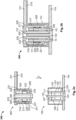
- Figure 1 shows a plug connector system 300 having a plug connector 100 and a plug connector mating piece 200 according to one embodiment in a connected state and a non-connected state.
- the plug connector system 300 is respectively illustrated in the non-connected and connected state in the graphics a) and b).
- the plug connector 100 has a connector housing 101.
- the connector housing 101 defines an outer receiving region 103, which is configured to receive a corresponding plug connector mating piece 200.
- the plug connector mating piece 200 is inserted into the plug connector 100 along the connection direction D, i.e. into the outer receiving region 103 of the connector housing 101.
- the plug connector 100 additionally has a contact socket 105.
- the contact socket 105 is arranged centrally in the receiving space 103 of the connector housing 101.
- the contact socket 105 is designed to make electrical contact with the plug connector mating piece 200.
- the contact socket 105 in the embodiment shown is sleeve-like and defines an inner receiving region 107 of the plug connector 100.
- a contact pin 201 of the plug connector mating piece 200 can be inserted into the inner receiving region 107.
- the contact pin 201 of the plug connector mating piece 200 is inserted into the inner receiving region 107 along the connection direction D.
- the sleeve-like contact socket 105 has an inner lateral surface 109 and an outer lateral surface 111.
- the inner lateral surface 109 restricts the inner receiving region 107.
- the outer lateral surface 111 defines an inner boundary wall of the outer receiving region 103.
- the outer receiving region 103 is arranged around the contact socket 105 and is thus arranged to run annularly concentrically around the inner receiving region 107.
- the contact socket 105 is formed from a metallic material. According to the invention, contact of the plug connector 100 with the plug connector mating piece 200 can thus be effected via making electrical contact of the inner lateral surface 109 of the contact socket 105 and/or of the outer lateral surface 111 of the contact socket 105 with a corresponding contact-making element of the plug connector mating piece 200.
- a contact spring 113 is formed on the inner lateral surface 109 of the contact socket 105.
- the contact spring 113 is configured to effect or to improve electrical contact of the contact socket 105 with the contact pin 201 of the plug connector mating piece 200.
- the contact spring 113 is annular.
- the annular contact spring 113 is arranged on the inner lateral surface 109, running around the inner receiving region 107.
- the contact spring 113 is arranged in a recess 125 provided for the purpose in the inner lateral surface 109.
- the contact spring 113 is removably arranged in the recess 125 in the inner lateral surface 109 of the contact socket.
- the contact spring 113 is capable of retaining, in the inner receiving region 107, the contact pin 201 of the plug connector mating piece 200 that is inserted into the inner receiving region 107 of the contact socket 105.
- the contact pin is pushed through the annular contact spring 113.
- the contact spring 113 additionally has an inwardly domed region 127. Via the domed region 127, the contact spring 113 is capable of exerting a contact pressure on the inserted contact pin 201 of the inserted plug connector mating piece 200. Thereby, the contact pin 201 of the plug connector mating piece 200 can be retained in the inner receiving region 107 of the contact socket 105.
- the contact spring 113 is made from a metallic material.
- the contact spring 113 can, for example, be made from a copper alloy.
- the plug connector 100 further comprises a guide pin 115.
- the guide pin is arranged centrally within the inner receiving region 107 of the contact socket 105.
- the guide pin 115 extends in a direction opposite to the connection direction D.
- the guide pin 115 is used to guide the plug connector mating piece 200 as it is inserted into the plug connector 100.
- the guide pin 115 is configured to be inserted counter to the connection direction D into a pin receiving region 205 defined by the contact pin 201 as the contact pin 201 of the plug connector mating piece 200 is inserted into the inner receiving region 107 of the contact socket 105.
- the mating of the plug connector 100 with the plug connector mating piece 200 can be improved, in that, by means of the guide pin 115, guidance of the plug connector mating piece 200 as it is inserted into the outer receiving region 103 of the connector housing 101 of the plug connector 100 is achieved.
- the guide pin 115 is connected to a guide base 123.
- the guide base 123 forms a termination of the contact socket.
- the guide pin 115 and/or the guide base 123 are made from an electrically insulating material.
- the guide pin 115 and/or the guide base 123 are made from plastic.
- the guide pin 115 and the guide base 123 are made in one piece.
- the contact socket 105 has a finger guard 117.
- the finger guard 117 is formed on an end of the contact socket 105 that is arranged opposite to the guide base 123.
- the finger guard 117 is made from an electrically insulating material, for example plastic.
- the contact socket 105 has a contact-making section 121. Via the contact-making section 121, electrical contact between the contact socket 105 and a conductor element to which the plug connector 100 is electrically conductively connected is achieved.
- the conductor element is designed as a bus bar 119.
- the plug connector 100 can be connected to a vehicle battery of a vehicle, in particular an electrically operable vehicle.
- the contact-making section is integrated directly in the bus bar 119.
- the guide base 123 is formed between the annular contact-making section 121.
- the connector housing 101 is made from an electrically insulating material, for example plastic.
- the plug connector mating piece 200 in the embodiment shown has the already described contact pin 201 with the pin receiving region 205.
- the contact pin 201 has an outer contact surface 103.
- the electrical contact between the plug connector 100 and the plug connector mating piece 200 inserted into the outer receiving region 103 of the plug connector 100 is made via an electrical contact between the outer contact surface 203 of the contact pin 201 and the inner lateral surface 109 of the contact socket 105 of the plug connector 100.
- the contact can additionally or alternatively be effected via the contact spring 113.
- the contact pin 201 is arranged centrally in a housing 209.
- the housing 209 defines a housing receiving region 210. As the plug connector mating piece 200 is inserted into the outer receiving region 103 of the connector housing 101 of the plug connector 100 along the connection direction D, the contact socket 105 of the plug connector 100 is received by the housing receiving region 210.
- the contact pin 201 is electrically connected to a cable 211 via a contact-making section 213.
- the contact pin 201 also has a finger guard made of an electrically insulating material, for example plastic.
- the housing 209 is likewise made from an electrically insulating material. In the embodiment shown, the housing 209 is connected to electrical insulation 215 of the cable 211. The connection of the housing 209 and the insulation 211 can in particular be made in one piece.
- the housing 209 is sleeve-like and, as the plug connector mating piece 200 is inserted into the plug connector 100, is received by the outer receiving region 103 of the connector housing 101.
- the inner lateral surface 109 and the outer lateral surface 111 of the contact socket 105 of the plug connector 100 define a contact-making area of 80 mm 2 for making an electrical contact.
- the outer contact surface 203 of the contact pin 201 of the plug connector mating piece 200 defines a contact-making area of 45 mm 2 for making the electrical contact.
- the plug connector mating piece 200 is designed here for a cable 211 having a cable cross section of 15-25 mm 2 .
- the plug connector system 300 is thus designed for a high-current connection of rated currents of up to 200 A and rated voltages of up to 800 V.
- the plug connector system 300 is shown in the connected state.
- the plug connector mating piece 200 has been inserted into the plug connector 100 along the connection direction D.
- the housing 209 of the plug connector mating piece 200 is received by the outer receiving region 103 of the connector housing 101 of the plug connector. Furthermore, the contact pin 201 of the plug connector mating piece 200 is received by the inner receiving region 107 of the contact socket 105. Analogously, the guide pin 115 of the plug connector 100 is received by the pin receiving region 205 of the contact pin 201 of the plug connector mating piece 200.
- the contact spring 113 in particular the domed region of the contact spring 113, is compressed by the contact pin 201 inserted into the inner receiving region 107 of the contact socket 105.
- the contact spring 113 is capable of exerting a contact pressure on the contact pin 201. Via the contact pressure, the electrical contact between the contact pin 201 and the contact socket 105 can be effected or improved.
- the contact pin 201 can be retained in the inner receiving region 107.
- the contact pin 201 contacts the inner lateral surface 109 of the contact sleeve 105 via its outer contact surface 203.
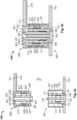
- Figure 2 shows a plug connector system 300 having a plug connector 100 and a plug connector mating piece 200 according to a further embodiment in a connected state and a non-connected state.
- the embodiment shown is based on the embodiment in figure 1 . As far as the configurations of the plug connector 100 and/or the plug connector mating piece 200 correspond to the configurations of the embodiment in figure 1 , a renewed detailed description will be dispensed with.
- the plug connector 100 differs from the embodiment in figure 1 only in the fact that the contact spring 113 has been removed.
- an electrical contact-making area of 80 mm 2 is still nevertheless provided by the inner lateral surface 109 and the outer lateral surface 111 of the contact socket 105.
- the plug connector mating piece 200 differs from the embodiment in figure 1 primarily in the fact that the electrical contact of the plug connector mating piece 200 is effected not via the contact pin 201 but via a mating contact socket 217.
- the mating contact socket 217 is sleeve-like and defines a socket receiving region 219.
- the mating contact socket 217 is arranged in the housing 209 in such a way that, when the plug connector mating piece 200 is connected to the plug connector 100, the contact socket 105 of the plug connector 100 is received by the socket receiving region 219.
- the sleeve-like mating contact socket 217 has an inner lateral surface 221.
- the inner lateral surface 221 is used to make electrical contact with the outer contact surface 111 of the contact socket 105 of the plug connector 100 when the contact socket 105 is received in the socket receiving region 219 of the mating contact socket 217.
- the mating contact socket 217 further has a contact spring 225.
- the contact spring 215 is sleeve-like and, running onto the socket receiving region 219, is arranged on the inner contact surface 221 of the mating contact socket 219.
- the contact spring 225 is arranged in a recess 223 in the inner contact surface 221 of the mating contact socket 217.
- the recess 223 is formed in the inner contact surface 221, running appropriately annularly around.
- the contact spring 215 has a domed region 233. As the contact socket 105 of the plug connector 100 is received in the socket receiving region 219, the domed region 233 is compressed by the contact socket 105. As a result, the contact spring is capable of exerting a contact pressure on the outer lateral surface 111 of the contact socket 105, whereby the electrical contact is improved and the contact socket 105 can be retained in the socket receiving region 219 of the mating contact socket 217.
- the contact pin 201 of the embodiment in figure 1 is replaced by a mating guide pin 202.
- the mating guide pin 202 is not used to make electrical contact but, exclusively in interaction with the guide pin 115 of the plug connector 100, ensures the guidance of the connection and of the mating of the plug connector 100 and the plug connector mating piece 200.
- the mating guide pin 202 has the pin receiving region 205, into which the guide pin 115 of the plug connector 100 can be inserted counter to the connection direction D as they are plugged together.
- the mating guide pin 202 is made from an electrically insulating material, for example plastic.
- the mating contact sleeve 217 is electrically conductively connected to the cable 211 via a contact-making region 229. Via the contact-making region 229, electrical contact of the plug connector mating piece 200 with the cable 211 is effected.
- the contact-making region 229 is formed in a base region 233 of the mating contact socket 217, which defines a termination of the mating contact socket 217.
- the mating contact socket 217 has a finger guard 227 formed at an end of the mating contact socket 217 arranged opposite to the contact-making region 229.
- the finger guard 227 is made from an electrically insulating material, for example plastic.
- the finger guard 227 is integrally connected to the housing 209.
- the electrical contact between the plug connector 100 and the plug connector mating piece 200 is effected via the contact between the inner contact surface 221 of the mating contact socket 217 and the outer lateral surface 111 of the contact socket 105.
- an electrical contact-making area of 95 mm 2 is provided by the inner lateral surface 221 of the mating contact socket 217.
- the plug connector mating piece 200 can thus be used for cables 211 with a cable cross section of 25-50 mm 2 .
- the plug connector system 300 in the embodiment shown can thus be used for high-current connections with rated currents up to 250 A and rated voltages up to 1000 V.
- the housing 209 with the mating contact socket 217 is received in the outer receiving region 103.
- the contact socket 105 is received in the socket receiving region 219.
- the outer lateral surface 111 of the contact socket 105 here contacts the inner contact surface 221 of the mating contact socket 217 and compresses the contact spring 225.
- the guide pin 115 is received in the pin receiving region 205 of the mating guide pin 202.
- Figure 3 shows a plug connector system 300 having a plug connector 100 and a plug connector mating piece 200 according to a further embodiment in a connected state and a non-connected state.
- the embodiment shown is based on a combination of the embodiments of figures 1 and 2 .
- the plug connector 100 corresponds to the embodiment of figure 1 and is unchanged relative to the latter.
- the plug connector mating piece 200 has the contact pin 201 of the embodiment in figure 1 and the mating contact socket 217 of the embodiment in figure 2 .
- the contact pin 201 is connected to the bottom surface of the mating contact socket 217 via a contact-making region 231.
- the electrical contact is effected via the contact pin 201 and the mating contact socket 217.
- the contact pin 201 contacts the inner lateral surface 109 of the contact socket 105 via the outer contact surface 203, and the inner contact surface 221 of the mating contact socket 217 contacts the outer lateral surface 111 of the contact socket 105.
- the plug connector mating piece 200 can be used for cables 211 with cable cross sections between 50 mm 2 and 120 mm 2 .
- the plug connector 100 of the invention can thus be used for plug connector mating pieces 200 according to the three embodiments described above. In this way, electrical high-current connections with rated currents between 200 and 320 A and rated voltages between 800 V and 1200 V can be effected via a plug connector 100. According to the embodiments described, the correspondingly described plug connector mating pieces 200 can be used for cables with cable cross sections between 15 mm 2 and 120 mm 2 .
- the plug connector system 300 permits a use in the automotive sector. In particular, a use in the electrical cabling of vehicle batteries, in particular of electrically operable vehicles, is possible.
- the plug connectors 100 suitable for the various cable cross sections and the various electrical connections with different rated currents and rated voltages can here in particular be installed or arranged directly on the battery. The different connections can be effected here via the different configurations of the plug connector mating pieces 200, as described above.
- the plug connector 100 as described above is thus suitable for effecting the different electrical high-current connections as described above.
- the connector housing 101, the contact socket 105 and the contact pin 201 are designed with a cylindrical form.
- the plug connector system 300 is thus suitable for round contact designs.
- the connector housing 101, the contact socket 105 and the contact pin 201 can alternatively also be formed with angular cross sections.
- the plug connector system 300 is suitable for flat contact designs.
Landscapes
- Details Of Connecting Devices For Male And Female Coupling (AREA)
- Coupling Device And Connection With Printed Circuit (AREA)
Abstract
A plug connector is designed such that a plug connector mating piece can be plugged together with the plug connector along a connection direction. The plug connector has a contact socket, via which electrical contact with a correspondingly designed contact connector mating piece can be effected. The contact socket is formed in such a way that an electrical contact with the plug connector mating piece can be achieved via a contact pin and/or a mating contact socket of the plug connector mating piece.
Description
- The present invention relates to a plug connector, a plug connector mating piece and a plug connector system.
- Plug connector systems are known from the prior art in many variants.
- One object of the present invention consists in providing a plug connector. A further object of the present invention consists in providing a plug connector mating piece. A further object of the present invention consists in providing a plug connector system.
- These objects are achieved by a plug connector, a plug connector mating piece and a plug connector system having the features of the independent claims. Various developments are specified in the dependent claims.
- According to one aspect of the invention, a plug connector is provided which is designed such that a plug connector mating piece can be plugged together with the plug connector along a connection direction, wherein the plug connector comprises a connector housing, the connector housing defines an outer receiving region, the outer receiving region is configured in such a way that the plug connector mating piece can be inserted into the outer receiving region along the connection direction, a contact socket is arranged in the outer receiving region, the contact socket is sleeve-like and defines an inner receiving region, the inner receiving region is configured in such a way that, when the plug connector mating piece is inserted into the outer receiving region, a contact pin of the plug connector mating piece can be inserted into the inner receiving region, the outer receiving region is configured in such a way that, when the plug connector mating piece is inserted into the outer receiving region, a mating contact socket of the plug connector mating piece can be inserted into the outer receiving region, the sleeve-like contact socket has an inner lateral surface for making contact with the contact pin of the plug connector mating piece and an outer lateral surface for making contact with the mating contact socket of the plug connector mating piece, and an electrical contact between the plug connector and the inserted plug connector mating piece can be effected via the inner lateral surface and/or the outer lateral surface.
- It is thereby possible to achieve the technical advantage that an improved plug connector can be provided. Here, the plug connector permits an electrical connection to an inserted plug connector mating piece via an electrical contact between the inner lateral surface and/or the outer lateral surface of the contact socket. Depending on the design of the respective plug connector mating piece, a contact can be achieved exclusively between the inner lateral surface of the contact socket, exclusively between the outer lateral surface of the contact socket or a contact between the inner lateral surface and the outer lateral surface of the contact socket. Because of the sleeve-like design of the contact socket, the inner lateral surface and the outer lateral surface provide contact-making surfaces of different sizes for the electrical contact with the plug connector mating piece. By virtue of the different contact-making surfaces, electrical connections can be provided for different current ranges. The larger the contact-making surface, the higher the currents that can be transmitted by the respective electrical connection.
- Depending on the design of the plug connector mating pieces, electrical connections for different current ranges and voltage ranges can thus be provided by the plug connector.
- According to the invention, a possible area of use of the plug connector is in vehicle construction and here, in particular, in a power supply of electrically operable vehicles. Here, the plug connector can be arranged on a vehicle battery. As a result of the wide applicability of the plug connector, which permits various electrical connections in different current ranges, a single model of the plug connector can be formed on the vehicle battery, which is configured to accommodate differently configured plug connector mating pieces and therefore to provide different electrical connections for different current ranges.
- Only one plug connector model is therefore needed for the different electrical connections in different current and/or voltage ranges. The different types of connection are each effected via the appropriately configured plug connector mating pieces, which are each configured to make contact only with the inner lateral surface, only the outer lateral surface or the inner and outer lateral surface of the contact socket.
- By means of the plug connector, it is thus possible to provide a plug connector which can be used for various plug connector mating pieces and which permits electrical connections for different current ranges. According to the invention, the plug connector is designed in particular for a high-current range.
- According to one embodiment, a contact spring which is provided to produce the electrically conductive connection between the contact socket and the contact pin of the plug connector mating piece which is inserted into the receiving region is arranged on the lateral surface of the contact socket.
- It is thereby possible to achieve the technical advantage that an optimized electrical contact between the inner lateral surface of the contact socket of the plug connector and the outer contact surface of the contact pin of the plug connector mating piece can be provided.
- According to one embodiment, the contact spring is sleeve-like, arranged on the inner lateral surface and running around the latter.
- It is thereby possible to achieve the technical advantage that an optimized electrical contact between the inner lateral surface of the contact socket of the plug connector and the outer contact surface of the contact pin of the plug connector mating piece can be provided. The sleeve-like contact spring can additionally improve the mechanical connection between the plug connector and the inserted plug connector mating piece, in that the contact pin of the plug connector mating piece is retained in the inner receiving region by the contact spring.
- According to one embodiment, the contact spring is removably arranged on the inner lateral surface of the contact socket.
- It is thereby possible to achieve the technical advantage that the plug connector can be used for various plug connector mating pieces. The contact-making area between the plug connector and the plug connector mating piece can be varied by removing or using the contact spring. Electrical connections, in particular in the high-current range, can hereby be implemented for different power classes.
- According to one embodiment, the inner lateral surface and the outer lateral surface of the contact socket provide a contact-making area of 80 mm2 for the electrical contact.
- It is thereby possible to achieve the technical advantage that the plug connector can be used for various plug connector mating pieces. In particular, a use in the high-current range is made possible. The plug connector permits electrical connection to plug connector mating pieces having cables with cable cross sections between 15 mm2 and 120 mm2. In particular, by using the plug connector according to the invention and a correspondingly designed plug connector mating piece, an electrical high-current connection with rated currents up to 350 A and rated voltages up to 1200 V can be achieved.
- According to one embodiment, the plug connector has a guide pin arranged in the inner receiving region, which is provided to be inserted into a receiving region of the contact pin of the plug connector mating piece, counter to the connection direction.
- It is thereby possible to achieve the technical advantage that secured mating of the plug connector with a plug connector mating piece is made possible via the guide pin. Here, when the plug connector is plugged together with the plug connector mating piece, the guide pin is inserted into a receiving region of a contact pin of the plug connector mating piece. The receiving region extends along a longitudinal axis of the contact pin, so that as a result of introducing the guide pin, the plug connector mating piece is guided by the guide pin as it is inserted. This permits secured insertion and mating.
- According to one embodiment, an electrically insulating finger guard is formed on the contact socket.
- It is thereby possible to achieve the technical advantage that the safety of the plug connector can be ensured via the finger guard. Because of the area of use of the plug connector in the high-current range, the finger guard reduces the risk of injury to users of the plug connector system.
- According to a further aspect, a plug connector mating piece is provided which is designed to be plugged together with a plug connector along a connection direction, wherein the plug connector mating piece comprises a contact pin, the contact pin is designed to be inserted along the connection direction into an inner receiving region defined by a contact socket of the plug connector, the contact pin defines an outer contact surface, and the making of an electrical contact between the plug connector and the plug connector mating piece can be effected via making an electrical contact between the outer contact surface of the contact pin and an inner lateral surface of the contact socket of the plug connector.
- It is thereby possible to achieve the technical advantage that an improved plug connector mating piece which can be plugged together with the plug connector according to the invention can be provided, with the aforementioned technical advantages. The plug connector mating piece is suitable in particular for use in the high-current range and is configured to transmit rated currents up to 200 A, rated voltages up to 800 V.
- According to one embodiment, the outer contact surface of the contact pin provides an electrical contact-making area of 45 mm2 for the electrical contact, wherein the plug connector mating piece is designed for an electrical high-current connection to a cable having a cable cross section of 15 mm2 to 35 mm2.
- It is thereby possible to achieve the technical advantage that a high-current connection can be provided. Via the 45 mm2 contact-making area, by using the plug connector according to the invention, it is possible to achieve an electrical contact which is configured to transmit rated currents up to 200 A and rated voltages of up to 800 V.
- According to a further aspect, a plug connector mating piece is provided which is designed to be plugged together with a plug connector along a connection direction, wherein the plug connector mating piece comprises a mating contact socket, the mating contact socket is sleeve-like and defines a receiving region, the receiving region is configured to receive a contact socket of the plug connector counter to the connection direction, the mating contact socket defines an inner contact surface, and an electrical contact between the plug connector and the plug connector mating piece can be effected via making an electrical contact between the inner contact surface of the mating contact socket of the plug connector mating piece and an outer lateral surface of the contact socket of the plug connector.
- It is thereby possible to achieve the technical advantage that an improved plug connector mating piece which can be plugged together with the plug connector according to the invention can be provided, with the aforementioned technical advantages. The plug connector mating piece is suitable in particular for a use in the high-current range and is configured to transmit rated currents up to 250 A and rated voltages up to 1000 V. An enlarged contact-making area with respect to the contact pin can be provided by the mating contact socket. This permits a transmission of increased currents.
- According to one embodiment, the plug connector mating piece also comprises a contact pin, wherein the contact pin is designed to be inserted along the connection direction into an inner receiving region defined by the contact socket of the plug connector, the contact pin defines an outer contact surface, and an electrical contact between the plug connector and the plug connector mating piece can be effected via making an electrical contact between the outer contact surface of the contact pin and an inner lateral surface of the contact socket and via making an electrical contact between the inner contact surface of the mating contact socket of the plug connector mating piece and the outer lateral surface of the contact socket of the plug connector.
- It is thereby possible to achieve the technical advantage that an improved plug connector mating piece which can be plugged together with the plug connector according to the invention can be provided, with the aforementioned technical advantages. The plug connector mating piece is suitable in particular for use in the high-current range and is configured to transmit rated currents up to 320 A and rated voltages of up to 1200 V. Via the combination of the contact pin and the mating contact socket, as compared with the contact pin and the mating contact socket on their own, an enlarged contact-making area can be provided. This permits a transmission of once more increased currents.
- According to one embodiment, the inner contact surface of the mating contact socket provides an electrical contact-making area of 95 mm2 for the electrical contact, wherein the plug connector mating piece is designed for an electrical high-current connection to a cable with a cable cross section of 20 mm2 to 50 mm2.
- It is thereby possible to achieve the technical advantage that a high-current connection can be provided. Via the 95 mm2 contact-making area of the mating contact socket, in combination with the plug connector according to the invention, a contact for rated currents up to 250 A and rated voltages of up to 1000 V can be achieved.
- According to one embodiment, the outer contact surface of the contact pin provides an electrical contact-making area of 45 mm2 for the electrical contact, wherein the inner contact surface of the mating contact socket provides an electrical contact-making area of 95 mm2 for the electrical contact, and wherein the plug connector mating piece is designed for an electrical high-current connection to a cable with a cable cross section of 50 mm2 to 120 mm2.
- It is thereby possible to achieve the technical advantage that a high-current contact can be provided. By means of the combination of the contact-making area of 45 mm2 of the contact pin and the contact-making area of 95 mm2 of the mating contact socket, in combination with the plug connector according to the invention, an electrical contact for rated currents of up to 350 A and rated voltages of up to 1200 V can be provided.
- According to one embodiment, a contact spring is formed on the inner contact surface of the mating contact socket, wherein the contact spring is configured to effect the electrical contact between the contact socket of the plug connector and the mating contact socket of the plug connector mating piece.
- It is thereby possible to achieve the technical advantage that an improved electrical contact between the contact socket of the plug connector and the mating contact socket of the plug connector mating piece is made possible via the contact spring. The contact spring can additionally improve a mechanical retaining action of the plug connector in the plug connector mating piece, so that the plug connector mating piece is inserted into the plug connector so as to be secured.
- According to one embodiment, the contact pin is sleeve-like and defines a receiving region, wherein the receiving region is configured to receive a guide pin of the plug connector counter to the connection direction.
- In this way, it is possible to achieve the technical advantage that, as a result of receiving the guide pin in the receiving region of the contact pin, secured mating of the plug connector with the plug connector mating piece is made possible. Here, the receiving region extends along a longitudinal axis of the contact pin.
- According to a further aspect, a plug connector system having a plug connector according to one of the preceding embodiments and a plug connector mating piece according to one of the preceding embodiments are provided.
- It is thereby possible to achieve the technical advantage that an improved plug connector system having a plug connector according to the invention and a plug connector mating piece according to the invention with the above technical advantages can be provided.
- The above-described properties, features and advantages of this invention will be explained in more detail below with reference to the appended figures. In the figures, in a respective schematic illustration:
- Figure 1
- shows a plug connector system having a plug connector and a plug connector mating piece according to one embodiment in a connected state and a non-connected state;
- Figure 2
- shows a plug connector system having a plug connector and a plug connector mating piece according to a further embodiment in a connected state and a non-connected state; and
- Figure 3
- shows a plug connector system having a plug connector and a plug connector mating piece according to a further embodiment in a connected state and a non-connected state.
-
Figure 1 shows aplug connector system 300 having aplug connector 100 and a plugconnector mating piece 200 according to one embodiment in a connected state and a non-connected state. - In
figures 1 to 3 , theplug connector system 300 is respectively illustrated in the non-connected and connected state in the graphics a) and b). - In the embodiment shown, the
plug connector 100 has aconnector housing 101. Theconnector housing 101 defines anouter receiving region 103, which is configured to receive a corresponding plugconnector mating piece 200. To plug theplug connector 100 and the plugconnector mating piece 200 together, according to the invention the plugconnector mating piece 200 is inserted into theplug connector 100 along the connection direction D, i.e. into theouter receiving region 103 of theconnector housing 101. - The
plug connector 100 additionally has acontact socket 105. Thecontact socket 105 is arranged centrally in the receivingspace 103 of theconnector housing 101. Thecontact socket 105 is designed to make electrical contact with the plugconnector mating piece 200. - The
contact socket 105 in the embodiment shown is sleeve-like and defines aninner receiving region 107 of theplug connector 100. Acontact pin 201 of the plugconnector mating piece 200 can be inserted into theinner receiving region 107. For this purpose, thecontact pin 201 of the plugconnector mating piece 200 is inserted into theinner receiving region 107 along the connection direction D. - The sleeve-
like contact socket 105 has an innerlateral surface 109 and an outerlateral surface 111. The innerlateral surface 109 restricts theinner receiving region 107. - The outer
lateral surface 111 defines an inner boundary wall of theouter receiving region 103. - In the embodiment shown, the
outer receiving region 103 is arranged around thecontact socket 105 and is thus arranged to run annularly concentrically around theinner receiving region 107. - The
contact socket 105 is formed from a metallic material. According to the invention, contact of theplug connector 100 with the plugconnector mating piece 200 can thus be effected via making electrical contact of the innerlateral surface 109 of thecontact socket 105 and/or of the outerlateral surface 111 of thecontact socket 105 with a corresponding contact-making element of the plugconnector mating piece 200. - In the embodiment shown, a
contact spring 113 is formed on the innerlateral surface 109 of thecontact socket 105. Thecontact spring 113 is configured to effect or to improve electrical contact of thecontact socket 105 with thecontact pin 201 of the plugconnector mating piece 200. - In the embodiment shown, the
contact spring 113 is annular. Theannular contact spring 113 is arranged on the innerlateral surface 109, running around theinner receiving region 107. - In the embodiment shown, the
contact spring 113 is arranged in arecess 125 provided for the purpose in the innerlateral surface 109. - According to one embodiment, the
contact spring 113 is removably arranged in therecess 125 in the innerlateral surface 109 of the contact socket. - As a result of the annular design, the
contact spring 113 is capable of retaining, in theinner receiving region 107, thecontact pin 201 of the plugconnector mating piece 200 that is inserted into theinner receiving region 107 of thecontact socket 105. For this purpose, as a result of the insertion of thecontact pin 201 along the connection direction D into theinner receiving region 107, the contact pin is pushed through theannular contact spring 113. - The
contact spring 113 additionally has an inwardly domed region 127. Via the domed region 127, thecontact spring 113 is capable of exerting a contact pressure on the insertedcontact pin 201 of the inserted plugconnector mating piece 200. Thereby, thecontact pin 201 of the plugconnector mating piece 200 can be retained in theinner receiving region 107 of thecontact socket 105. - As a result of the contact pressure of the
contact spring 113 of thecontact socket 105, an electrical contact between the insertedcontact pin 201 and thecontact socket 105 can also be improved. - According to the invention, the
contact spring 113 is made from a metallic material. Thecontact spring 113 can, for example, be made from a copper alloy. - In the embodiment shown, the
plug connector 100 further comprises aguide pin 115. The guide pin is arranged centrally within theinner receiving region 107 of thecontact socket 105. Theguide pin 115 extends in a direction opposite to the connection direction D. - The
guide pin 115 is used to guide the plugconnector mating piece 200 as it is inserted into theplug connector 100. For this purpose, theguide pin 115 is configured to be inserted counter to the connection direction D into apin receiving region 205 defined by thecontact pin 201 as thecontact pin 201 of the plugconnector mating piece 200 is inserted into theinner receiving region 107 of thecontact socket 105. - Via the insertion of the
guide pin 115 into thepin receiving region 205 of thecontact pin 201 of the plugconnector mating piece 200, the mating of theplug connector 100 with the plugconnector mating piece 200 can be improved, in that, by means of theguide pin 115, guidance of the plugconnector mating piece 200 as it is inserted into theouter receiving region 103 of theconnector housing 101 of theplug connector 100 is achieved. - In the embodiment shown, the
guide pin 115 is connected to aguide base 123. In the embodiment shown, theguide base 123 forms a termination of the contact socket. - According to one embodiment, the
guide pin 115 and/or theguide base 123 are made from an electrically insulating material. For example, theguide pin 115 and/or theguide base 123 are made from plastic. According to one embodiment, theguide pin 115 and theguide base 123 are made in one piece. - In the embodiment shown, the
contact socket 105 has afinger guard 117. Thefinger guard 117 is formed on an end of thecontact socket 105 that is arranged opposite to theguide base 123. Thefinger guard 117 is made from an electrically insulating material, for example plastic. - In the embodiment shown, the
contact socket 105 has a contact-makingsection 121. Via the contact-makingsection 121, electrical contact between thecontact socket 105 and a conductor element to which theplug connector 100 is electrically conductively connected is achieved. - In the embodiment shown, the conductor element is designed as a
bus bar 119. According to one embodiment, theplug connector 100 can be connected to a vehicle battery of a vehicle, in particular an electrically operable vehicle. - In the embodiment shown, the contact-making section is integrated directly in the
bus bar 119. - Here, the
guide base 123 is formed between the annular contact-makingsection 121. - According to one embodiment, the
connector housing 101 is made from an electrically insulating material, for example plastic. - The plug
connector mating piece 200 in the embodiment shown has the already describedcontact pin 201 with thepin receiving region 205. Thecontact pin 201 has anouter contact surface 103. In the embodiment shown, the electrical contact between theplug connector 100 and the plugconnector mating piece 200 inserted into theouter receiving region 103 of theplug connector 100 is made via an electrical contact between theouter contact surface 203 of thecontact pin 201 and the innerlateral surface 109 of thecontact socket 105 of theplug connector 100. In the embodiment shown, the contact can additionally or alternatively be effected via thecontact spring 113. - The
contact pin 201 is arranged centrally in ahousing 209. Thehousing 209 defines ahousing receiving region 210. As the plugconnector mating piece 200 is inserted into theouter receiving region 103 of theconnector housing 101 of theplug connector 100 along the connection direction D, thecontact socket 105 of theplug connector 100 is received by thehousing receiving region 210. - In the embodiment shown, the
contact pin 201 is electrically connected to acable 211 via a contact-makingsection 213. - Hereby, an electrical connection between the plug
connector mating piece 200 and thecable 211 is achieved. - In the embodiment shown, the
contact pin 201 also has a finger guard made of an electrically insulating material, for example plastic. - In the embodiment shown, the
housing 209 is likewise made from an electrically insulating material. In the embodiment shown, thehousing 209 is connected toelectrical insulation 215 of thecable 211. The connection of thehousing 209 and theinsulation 211 can in particular be made in one piece. - In the embodiment shown, the
housing 209 is sleeve-like and, as the plugconnector mating piece 200 is inserted into theplug connector 100, is received by theouter receiving region 103 of theconnector housing 101. - According to one embodiment, the inner
lateral surface 109 and the outerlateral surface 111 of thecontact socket 105 of theplug connector 100 define a contact-making area of 80 mm2 for making an electrical contact. - The
outer contact surface 203 of thecontact pin 201 of the plugconnector mating piece 200 defines a contact-making area of 45 mm2 for making the electrical contact. The plugconnector mating piece 200 is designed here for acable 211 having a cable cross section of 15-25 mm2. - In the embodiment shown, the
plug connector system 300 is thus designed for a high-current connection of rated currents of up to 200 A and rated voltages of up to 800 V. - In graphic b), the
plug connector system 300 is shown in the connected state. The plugconnector mating piece 200 has been inserted into theplug connector 100 along the connection direction D. - To mate the
plug connector 100 and the plugconnector mating piece 200 along the connection direction, thehousing 209 of the plugconnector mating piece 200 is received by theouter receiving region 103 of theconnector housing 101 of the plug connector. Furthermore, thecontact pin 201 of the plugconnector mating piece 200 is received by theinner receiving region 107 of thecontact socket 105. Analogously, theguide pin 115 of theplug connector 100 is received by thepin receiving region 205 of thecontact pin 201 of the plugconnector mating piece 200. - The
contact spring 113, in particular the domed region of thecontact spring 113, is compressed by thecontact pin 201 inserted into theinner receiving region 107 of thecontact socket 105. Hereby, thecontact spring 113 is capable of exerting a contact pressure on thecontact pin 201. Via the contact pressure, the electrical contact between thecontact pin 201 and thecontact socket 105 can be effected or improved. In addition, thecontact pin 201 can be retained in theinner receiving region 107. - Besides the
contact spring 113, thecontact pin 201 contacts the innerlateral surface 109 of thecontact sleeve 105 via itsouter contact surface 203. - Via the contact shown, an electrical high-current connection with rated currents up to 200 A and related voltages up to 800 V is made possible.
-
Figure 2 shows aplug connector system 300 having aplug connector 100 and a plugconnector mating piece 200 according to a further embodiment in a connected state and a non-connected state. - The embodiment shown is based on the embodiment in
figure 1 . As far as the configurations of theplug connector 100 and/or the plugconnector mating piece 200 correspond to the configurations of the embodiment infigure 1 , a renewed detailed description will be dispensed with. - In the embodiment shown, the
plug connector 100 differs from the embodiment infigure 1 only in the fact that thecontact spring 113 has been removed. - In the embodiment shown, an electrical contact-making area of 80 mm2 is still nevertheless provided by the inner
lateral surface 109 and the outerlateral surface 111 of thecontact socket 105. - In the embodiment shown, the plug
connector mating piece 200 differs from the embodiment infigure 1 primarily in the fact that the electrical contact of the plugconnector mating piece 200 is effected not via thecontact pin 201 but via amating contact socket 217. - The
mating contact socket 217 is sleeve-like and defines asocket receiving region 219. Themating contact socket 217 is arranged in thehousing 209 in such a way that, when the plugconnector mating piece 200 is connected to theplug connector 100, thecontact socket 105 of theplug connector 100 is received by thesocket receiving region 219. - The sleeve-like
mating contact socket 217 has an innerlateral surface 221. The innerlateral surface 221 is used to make electrical contact with theouter contact surface 111 of thecontact socket 105 of theplug connector 100 when thecontact socket 105 is received in thesocket receiving region 219 of themating contact socket 217. - In the embodiment shown, the
mating contact socket 217 further has acontact spring 225. Thecontact spring 215 is sleeve-like and, running onto thesocket receiving region 219, is arranged on theinner contact surface 221 of themating contact socket 219. For this purpose, thecontact spring 225 is arranged in arecess 223 in theinner contact surface 221 of themating contact socket 217. Therecess 223 is formed in theinner contact surface 221, running appropriately annularly around. - The
contact spring 215 has adomed region 233. As thecontact socket 105 of theplug connector 100 is received in thesocket receiving region 219, thedomed region 233 is compressed by thecontact socket 105. As a result, the contact spring is capable of exerting a contact pressure on the outerlateral surface 111 of thecontact socket 105, whereby the electrical contact is improved and thecontact socket 105 can be retained in thesocket receiving region 219 of themating contact socket 217. - In the embodiment shown, the
contact pin 201 of the embodiment infigure 1 is replaced by amating guide pin 202. Themating guide pin 202 is not used to make electrical contact but, exclusively in interaction with theguide pin 115 of theplug connector 100, ensures the guidance of the connection and of the mating of theplug connector 100 and the plugconnector mating piece 200. - For this purpose, in a manner analogous to the
contact pin 201, themating guide pin 202 has thepin receiving region 205, into which theguide pin 115 of theplug connector 100 can be inserted counter to the connection direction D as they are plugged together. - In the embodiment shown, the
mating guide pin 202 is made from an electrically insulating material, for example plastic. - In the embodiment shown, the
mating contact sleeve 217 is electrically conductively connected to thecable 211 via a contact-makingregion 229. Via the contact-makingregion 229, electrical contact of the plugconnector mating piece 200 with thecable 211 is effected. The contact-makingregion 229 is formed in abase region 233 of themating contact socket 217, which defines a termination of themating contact socket 217. - In the embodiment shown, the
mating contact socket 217 has afinger guard 227 formed at an end of themating contact socket 217 arranged opposite to the contact-makingregion 229. Thefinger guard 227 is made from an electrically insulating material, for example plastic. In the embodiment shown, thefinger guard 227 is integrally connected to thehousing 209. - As the
plug connector 100 is plugged together with the plugconnector mating piece 200, the electrical contact between theplug connector 100 and the plugconnector mating piece 200 is effected via the contact between theinner contact surface 221 of themating contact socket 217 and the outerlateral surface 111 of thecontact socket 105. - In the embodiment shown, an electrical contact-making area of 95 mm2 is provided by the inner
lateral surface 221 of themating contact socket 217. The plugconnector mating piece 200 can thus be used forcables 211 with a cable cross section of 25-50 mm2. - The
plug connector system 300 in the embodiment shown can thus be used for high-current connections with rated currents up to 250 A and rated voltages up to 1000 V. - In the connected state, as illustrated in graphic b), the
housing 209 with themating contact socket 217 is received in theouter receiving region 103. By contrast, thecontact socket 105 is received in thesocket receiving region 219. The outerlateral surface 111 of thecontact socket 105 here contacts theinner contact surface 221 of themating contact socket 217 and compresses thecontact spring 225. Theguide pin 115 is received in thepin receiving region 205 of themating guide pin 202. -
Figure 3 shows aplug connector system 300 having aplug connector 100 and a plugconnector mating piece 200 according to a further embodiment in a connected state and a non-connected state. - The embodiment shown is based on a combination of the embodiments of
figures 1 and2 . - The
plug connector 100 corresponds to the embodiment offigure 1 and is unchanged relative to the latter. - The plug
connector mating piece 200 has thecontact pin 201 of the embodiment infigure 1 and themating contact socket 217 of the embodiment infigure 2 . - In the embodiment shown, the
contact pin 201 is connected to the bottom surface of themating contact socket 217 via a contact-makingregion 231. - In the embodiment shown, the electrical contact is effected via the
contact pin 201 and themating contact socket 217. Thecontact pin 201 contacts the innerlateral surface 109 of thecontact socket 105 via theouter contact surface 203, and theinner contact surface 221 of themating contact socket 217 contacts the outerlateral surface 111 of thecontact socket 105. - Via a combination of the
outer contact surface 203 of thecontact pin 201 and theinner contact surface 221 of themating contact socket 217, an electrical contact-making area of 45 mm2 + 90 mm2 = 135 mm2 can be effected. In this way, the plugconnector mating piece 200 can be used forcables 211 with cable cross sections between 50 mm2 and 120 mm2. - In this way, by means of the
plug connector system 200, a high-current connection with rated currents up to 320 A and rated voltages up to 1200 V can be provided. - The
plug connector 100 of the invention according to the above-described embodiments can thus be used for plugconnector mating pieces 200 according to the three embodiments described above. In this way, electrical high-current connections with rated currents between 200 and 320 A and rated voltages between 800 V and 1200 V can be effected via aplug connector 100. According to the embodiments described, the correspondingly described plugconnector mating pieces 200 can be used for cables with cable cross sections between 15 mm2 and 120 mm2. - The
plug connector system 300 permits a use in the automotive sector. In particular, a use in the electrical cabling of vehicle batteries, in particular of electrically operable vehicles, is possible. Theplug connectors 100 suitable for the various cable cross sections and the various electrical connections with different rated currents and rated voltages can here in particular be installed or arranged directly on the battery. The different connections can be effected here via the different configurations of the plugconnector mating pieces 200, as described above. Theplug connector 100 as described above is thus suitable for effecting the different electrical high-current connections as described above. - In the above embodiments, the
connector housing 101, thecontact socket 105 and thecontact pin 201 are designed with a cylindrical form. Theplug connector system 300 is thus suitable for round contact designs. However, theconnector housing 101, thecontact socket 105 and thecontact pin 201 can alternatively also be formed with angular cross sections. In this embodiment, theplug connector system 300 is suitable for flat contact designs. -
- 100
- Plug connector
- 101
- Connector housing
- 103
- Outer receiving region
- 105
- Contact socket
- 107
- Inner receiving region
- 109
- Inner lateral surface
- 111
- Outer lateral surface
- 113
- Contact spring
- 115
- Guide pin
- 117
- Finger guard
- 119
- Bus bar
- 121
- Contact-making section
- 123
- Guide base
- 125
- Recess
- 127
- Domed region
- 200
- Plug connector mating piece
- 201
- Contact pin
- 202
- Mating guide pin
- 203
- Outer contact surface
- 205
- Pin receiving region
- 207
- Finger guard
- 209
- Housing
- 210
- Housing receiving region
- 211
- Cable
- 213
- Contact-making section
- 215
- Insulation
- 217
- Mating contact socket
- 219
- Socket receiving region
- 221
- Inner contact surface
- 223
- Recess
- 225
- Contact spring
- 227
- Finger guard
- 229
- Contact-making section
- 231
- Contact-making section
- 233
- Base region
- 235
- Domed region
- 300
- Plug connector system
- D
- Connection direction
Claims (16)
- A plug connector (100), which is designed such that a plug connector mating piece (200) can be plugged together with the plug connector (100) along a connection direction (D),
wherein the plug connector (100) comprises a connector housing (101), the connector housing (101) defines an outer receiving region (103), the outer receiving region (103) is configured in such a way that the plug connector mating piece (200) can be inserted into the outer receiving region (103) along the connection direction (D), a contact socket (105) is arranged in the outer receiving region (103), the contact socket (105) is sleeve-like and defines an inner receiving region (107), the inner receiving region (107) is configured in such a way that, when the plug connector mating piece (200) is inserted into the outer receiving region (103), a contact pin (201) of the plug connector mating piece (200) can be inserted into the inner receiving region (107), the outer receiving region (103) is configured in such a way that, when the plug connector mating piece (200) is inserted into the outer receiving region (103), a mating contact socket (217) of the plug connector mating piece (200) can be inserted into the outer receiving region (103), the sleeve-like contact socket (105) has an inner lateral surface (109) for making contact with the contact pin (201) of the plug connector mating piece (200) and an outer lateral surface (111) for making contact with the mating contact socket (217) of the plug connector mating piece (200), and an electrical contact between the plug connector (100) and the inserted plug connector mating piece (200) can be effected via the inner lateral surface (109) and/or the outer lateral surface (111). - The plug connector (100) as claimed in claim 1, wherein a contact spring (113) which is provided to produce the electrically conductive connection between the contact socket (105) and the contact pin (201) of the plug connector mating piece (200) that is inserted into the inner receiving region (107) is arranged on the inner lateral surface (109) of the contact socket (105).
- The plug connector (100) as claimed in the preceding claim 2, wherein the contact spring (113) is sleeve-like and, running around the inner lateral surface (109), is arranged on the inner lateral surface (109) of the contact sleeve (105).
- The plug connector (100) as claimed in one of the preceding claims 2 to 3, wherein the contact spring (113) is removably arranged on the inner lateral surface (109) of the contact socket (105).
- The plug connector (100) as claimed in one of the preceding claims, wherein the inner lateral surface (109) and the outer lateral surface (111) of the contact socket (105) provide a contact-making area of 80 mm2 for the electrical contact.
- The plug connector (100) as claimed in one of the preceding claims, wherein the plug connector (100) has a guide pin (115) arranged in the inner receiving region (107), which is provided to be inserted into a pin receiving region (205) of the contact pin (201) of the plug connector mating piece (200), counter to the connection direction (D).
- The plug connector (100) as claimed in one of the preceding claims, wherein an electrically insulating finger guard (117) is formed on the contact socket (105).
- A plug connector mating piece (200), which is designed to be plugged together with a plug connector (100) along a connection direction (D), wherein the plug connector mating piece (200) comprises a contact pin (201), the contact pin (201) is designed to be inserted along the connection direction (D) into an inner receiving region (107) defined by a contact socket (105) of the plug connector (100), the contact pin (201) defines an outer contact surface (203), and the making of an electrical contact between the plug connector (100) and the plug connector mating piece (200) can be effected via making an electrical contact between the outer contact surface (203) of the contact pin (201) and an inner lateral surface (109) of the contact socket (105) of the plug connector (100).
- The plug connector mating piece (200) as claimed in claim 8, wherein the outer contact surface (203) of the contact pin (201) provides an electrical contact-making area of 45 mm2 for the electrical contact, and wherein the plug connector mating piece (200) is designed for an electrical high-current connection to a cable (211) with a cable cross section of 15 mm2 to 35 mm2.
- A plug connector mating piece (200), which is designed to be plugged together with a plug connector (100) along a connection direction (D), wherein the plug connector mating piece (200) comprises a mating contact socket (217), the mating contact socket (217) is sleeve-like and defines a socket receiving region (219), the socket receiving region (219) is configured to receive a contact socket (105) of the plug connector (100) counter to the connection direction (D), the mating contact socket (217) defines an inner contact surface (221), and an electrical contact between the plug connector (100) and the plug connector mating piece (200) can be effected via making an electrical contact between the inner contact surface (221) of the mating contact socket (217) of the plug connector mating piece (200) and an outer lateral surface (111) of the contact socket (105) of the plug connector (100) .
- The plug connector mating piece (200) as claimed in claim 10, wherein the plug connector mating piece (200) also comprises a contact pin (201), wherein the contact pin (201) is designed to be inserted along the connection direction (D) into an inner receiving region (107) defined by the contact socket (105) of the plug connector (100), the contact pin (201) defines an outer contact surface (203), and electrical contact between the plug connector (100) and the plug connector mating piece (200) can be effected via making an electrical contact between the outer contact surface (203) of the contact pin (201) and an inner lateral surface (109) of the contact socket (105) and via making an electrical contact between the inner contact surface (221) of the mating contact socket (217) of the plug connector mating piece (200) and the outer lateral surface (111) of the contact socket (105) of the plug connector (100).
- The plug connector mating piece (200) as claimed in claim 10, wherein the inner contact surface (221) of the mating contact socket (217) provides an electrical contact-making area of 95 mm2 for the electrical contact, and wherein the plug connector mating piece is designed for an electrical high-current connection to a cable (211) with a cable cross section of 20 mm2 to 50 mm2.
- The plug connector mating piece (200) as claimed in claim 11, wherein the outer contact surface (203) of the contact pin (201) provides an electrical contact-making area of 45 mm2 for the electrical contact, wherein the inner contact surface (221) of the mating contact socket (217) provides an electrical contact-making area of 95 mm2 for the electrical contact, and wherein the plug connector mating piece (200) is designed for an electrical high-current connection to a cable (211) with a cable cross section of 50 mm2 to 120 mm2.
- The plug connector mating piece (200) as claimed in one of claims 10 to 13, wherein a contact spring (225) is formed on the inner contact surface (221) of the mating contact socket (217), and wherein the contact spring (225) is configured to effect the electrical contact between the contact socket (105) of the plug connector (100) and the mating contact socket (217) of the plug connector mating piece (200).
- The plug connector mating piece (200) as claimed in 8 or 11, wherein the contact pin (201) is sleeve-like and defines a pin receiving region (205), and wherein the pin receiving region (205) is configured to receive a guide pin (115) of the plug connector (100) counter to the connection direction (D).
- A plug connector system (300) comprising a plug connector (100) as claimed in one of the preceding claims 1 to 7 and a plug connector mating piece (200) as claimed in one of the preceding claims 8 to 15.
Applications Claiming Priority (1)
| Application Number | Priority Date | Filing Date | Title |
|---|---|---|---|
| DE102023118722.8A DE102023118722A1 (en) | 2023-07-14 | 2023-07-14 | connector, connector counterpart and connector system |
Publications (1)
| Publication Number | Publication Date |
|---|---|
| EP4492581A1 true EP4492581A1 (en) | 2025-01-15 |
Family
ID=91924569
Family Applications (1)
| Application Number | Title | Priority Date | Filing Date |
|---|---|---|---|
| EP24187907.1A Pending EP4492581A1 (en) | 2023-07-14 | 2024-07-11 | Plug connector, plug connector mating piece and plug connector system |
Country Status (5)
| Country | Link |
|---|---|
| US (1) | US20250023276A1 (en) |
| EP (1) | EP4492581A1 (en) |
| JP (1) | JP7787246B2 (en) |
| CN (1) | CN119315317A (en) |
| DE (1) | DE102023118722A1 (en) |
Citations (2)
| Publication number | Priority date | Publication date | Assignee | Title |
|---|---|---|---|---|
| DE102020112117A1 (en) * | 2020-05-05 | 2021-11-11 | Te Connectivity Germany Gmbh | Connector, connector counterpart and connector system |
| US20220384973A1 (en) * | 2021-06-01 | 2022-12-01 | Aptiv Technologies Limited | Male and female power terminal assembly, female and male power terminals |
Family Cites Families (2)
| Publication number | Priority date | Publication date | Assignee | Title |
|---|---|---|---|---|
| JP2002373729A (en) * | 2001-06-13 | 2002-12-26 | Join:Kk | Circular connector |
| JP2019200844A (en) | 2018-05-14 | 2019-11-21 | 矢崎総業株式会社 | Female connector and mating connector |
-
2023
- 2023-07-14 DE DE102023118722.8A patent/DE102023118722A1/en active Pending
-
2024
- 2024-07-10 US US18/768,735 patent/US20250023276A1/en active Pending
- 2024-07-10 JP JP2024110631A patent/JP7787246B2/en active Active
- 2024-07-11 CN CN202410926533.6A patent/CN119315317A/en active Pending
- 2024-07-11 EP EP24187907.1A patent/EP4492581A1/en active Pending
Patent Citations (2)
| Publication number | Priority date | Publication date | Assignee | Title |
|---|---|---|---|---|
| DE102020112117A1 (en) * | 2020-05-05 | 2021-11-11 | Te Connectivity Germany Gmbh | Connector, connector counterpart and connector system |
| US20220384973A1 (en) * | 2021-06-01 | 2022-12-01 | Aptiv Technologies Limited | Male and female power terminal assembly, female and male power terminals |
Also Published As
| Publication number | Publication date |
|---|---|
| JP2025013262A (en) | 2025-01-24 |
| DE102023118722A1 (en) | 2025-01-16 |
| CN119315317A (en) | 2025-01-14 |
| JP7787246B2 (en) | 2025-12-16 |
| US20250023276A1 (en) | 2025-01-16 |
Similar Documents
| Publication | Publication Date | Title |
|---|---|---|
| EP3584889B1 (en) | Connector device | |
| US10340623B2 (en) | Car charging plug-in connector | |
| EP3667828B1 (en) | Contact member for electrical connector | |
| EP3726660B1 (en) | High-voltage finger protection | |
| US4895530A (en) | Quick disconnect automotive battery connector | |
| US10840648B2 (en) | Shield terminal and shield connector | |
| CN108475889A (en) | High-power electric connector | |
| EP4099519B1 (en) | Male and female power terminal assembly, female and male power terminals | |
| US10644414B2 (en) | Terminal fitting and connector | |
| US5135417A (en) | Dual usage electrical/electronic pin terminal system | |
| EP4274033A1 (en) | Electrical power connector assembly | |
| KR101248896B1 (en) | Plug housing and electrical plug for transmitting electrical drive power | |
| US9017107B2 (en) | Insertion-type connector having a contact-making member | |
| US20250023276A1 (en) | Plug connector, plug connector mating piece and plug connector system | |
| US11258215B2 (en) | High voltage connector | |
| CN112290265A (en) | Female power contact | |
| CN121002737A (en) | High-power plug connector system | |
| EP4262028A1 (en) | Electric connector assembly for a high-voltage terminal and method for assembling | |
| EP4439870A1 (en) | Female contact with at least one new wire assembly | |
| EP4283789A1 (en) | Electrical safety connector | |
| JP2019193416A (en) | Cable connection part | |
| CN118156862A (en) | Power connector with removable touch-proof element | |
| WO2013076521A1 (en) | Plug, electrical connector, harness and method of assembly |
Legal Events
| Date | Code | Title | Description |
|---|---|---|---|
| PUAI | Public reference made under article 153(3) epc to a published international application that has entered the european phase |
Free format text: ORIGINAL CODE: 0009012 |
|
| STAA | Information on the status of an ep patent application or granted ep patent |
Free format text: STATUS: THE APPLICATION HAS BEEN PUBLISHED |
|
| AK | Designated contracting states |
Kind code of ref document: A1 Designated state(s): AL AT BE BG CH CY CZ DE DK EE ES FI FR GB GR HR HU IE IS IT LI LT LU LV MC ME MK MT NL NO PL PT RO RS SE SI SK SM TR |
|
| STAA | Information on the status of an ep patent application or granted ep patent |
Free format text: STATUS: REQUEST FOR EXAMINATION WAS MADE |
|
| 17P | Request for examination filed |
Effective date: 20250714 |