EP4492578A1 - Terminal assembly with terminal inspection port and methods of assembling same - Google Patents
Terminal assembly with terminal inspection port and methods of assembling same Download PDFInfo
- Publication number
- EP4492578A1 EP4492578A1 EP24186154.1A EP24186154A EP4492578A1 EP 4492578 A1 EP4492578 A1 EP 4492578A1 EP 24186154 A EP24186154 A EP 24186154A EP 4492578 A1 EP4492578 A1 EP 4492578A1
- Authority
- EP
- European Patent Office
- Prior art keywords
- terminal
- opening
- connection
- assembly
- shield
- Prior art date
- Legal status (The legal status is an assumption and is not a legal conclusion. Google has not performed a legal analysis and makes no representation as to the accuracy of the status listed.)
- Pending
Links
Images






Classifications
-
- H—ELECTRICITY
- H01—ELECTRIC ELEMENTS
- H01R—ELECTRICALLY-CONDUCTIVE CONNECTIONS; STRUCTURAL ASSOCIATIONS OF A PLURALITY OF MUTUALLY-INSULATED ELECTRICAL CONNECTING ELEMENTS; COUPLING DEVICES; CURRENT COLLECTORS
- H01R13/00—Details of coupling devices of the kinds covered by groups H01R12/70 or H01R24/00 - H01R33/00
- H01R13/40—Securing contact members in or to a base or case; Insulating of contact members
- H01R13/42—Securing in a demountable manner
-
- H—ELECTRICITY
- H01—ELECTRIC ELEMENTS
- H01R—ELECTRICALLY-CONDUCTIVE CONNECTIONS; STRUCTURAL ASSOCIATIONS OF A PLURALITY OF MUTUALLY-INSULATED ELECTRICAL CONNECTING ELEMENTS; COUPLING DEVICES; CURRENT COLLECTORS
- H01R13/00—Details of coupling devices of the kinds covered by groups H01R12/70 or H01R24/00 - H01R33/00
- H01R13/40—Securing contact members in or to a base or case; Insulating of contact members
-
- H—ELECTRICITY
- H01—ELECTRIC ELEMENTS
- H01R—ELECTRICALLY-CONDUCTIVE CONNECTIONS; STRUCTURAL ASSOCIATIONS OF A PLURALITY OF MUTUALLY-INSULATED ELECTRICAL CONNECTING ELEMENTS; COUPLING DEVICES; CURRENT COLLECTORS
- H01R13/00—Details of coupling devices of the kinds covered by groups H01R12/70 or H01R24/00 - H01R33/00
- H01R13/02—Contact members
-
- H—ELECTRICITY
- H01—ELECTRIC ELEMENTS
- H01R—ELECTRICALLY-CONDUCTIVE CONNECTIONS; STRUCTURAL ASSOCIATIONS OF A PLURALITY OF MUTUALLY-INSULATED ELECTRICAL CONNECTING ELEMENTS; COUPLING DEVICES; CURRENT COLLECTORS
- H01R13/00—Details of coupling devices of the kinds covered by groups H01R12/70 or H01R24/00 - H01R33/00
- H01R13/648—Protective earth or shield arrangements on coupling devices, e.g. anti-static shielding
- H01R13/658—High frequency shielding arrangements, e.g. against EMI [Electro-Magnetic Interference] or EMP [Electro-Magnetic Pulse]
- H01R13/6581—Shield structure
- H01R13/6585—Shielding material individually surrounding or interposed between mutually spaced contacts
-
- H—ELECTRICITY
- H01—ELECTRIC ELEMENTS
- H01R—ELECTRICALLY-CONDUCTIVE CONNECTIONS; STRUCTURAL ASSOCIATIONS OF A PLURALITY OF MUTUALLY-INSULATED ELECTRICAL CONNECTING ELEMENTS; COUPLING DEVICES; CURRENT COLLECTORS
- H01R24/00—Two-part coupling devices, or either of their cooperating parts, characterised by their overall structure
- H01R24/38—Two-part coupling devices, or either of their cooperating parts, characterised by their overall structure having concentrically or coaxially arranged contacts
- H01R24/40—Two-part coupling devices, or either of their cooperating parts, characterised by their overall structure having concentrically or coaxially arranged contacts specially adapted for high frequency
- H01R24/54—Intermediate parts, e.g. adapters, splitters or elbows
- H01R24/545—Elbows
-
- H—ELECTRICITY
- H01—ELECTRIC ELEMENTS
- H01R—ELECTRICALLY-CONDUCTIVE CONNECTIONS; STRUCTURAL ASSOCIATIONS OF A PLURALITY OF MUTUALLY-INSULATED ELECTRICAL CONNECTING ELEMENTS; COUPLING DEVICES; CURRENT COLLECTORS
- H01R43/00—Apparatus or processes specially adapted for manufacturing, assembling, maintaining, or repairing of line connectors or current collectors or for joining electric conductors
- H01R43/20—Apparatus or processes specially adapted for manufacturing, assembling, maintaining, or repairing of line connectors or current collectors or for joining electric conductors for assembling or disassembling contact members with insulating base, case or sleeve
-
- H—ELECTRICITY
- H01—ELECTRIC ELEMENTS
- H01R—ELECTRICALLY-CONDUCTIVE CONNECTIONS; STRUCTURAL ASSOCIATIONS OF A PLURALITY OF MUTUALLY-INSULATED ELECTRICAL CONNECTING ELEMENTS; COUPLING DEVICES; CURRENT COLLECTORS
- H01R9/00—Structural associations of a plurality of mutually-insulated electrical connecting elements, e.g. terminal strips or terminal blocks; Terminals or binding posts mounted upon a base or in a case; Bases therefor
- H01R9/03—Connectors arranged to contact a plurality of the conductors of a multiconductor cable, e.g. tapping connections
- H01R9/05—Connectors arranged to contact a plurality of the conductors of a multiconductor cable, e.g. tapping connections for coaxial cables
- H01R9/0518—Connection to outer conductor by crimping or by crimping ferrule
Definitions
- This disclosure is directed to a terminal assembly, particularly to a terminal assembly having one or more terminal inspection ports which allows visual confirmation of proper seating and/or connection of electrical terminals within the connector.
- Terminal assemblies may have a blind plug and socket connection between a male plug terminal and a female socket terminal within an insulator or connector housing.
- Blind plug and socket connections cause a risk of lower quality due to a partial or improper plugging of the male terminal within the female socket terminal which could lead to poor or intermittent performance of the connector.
- Some previous connector designs had a slot configured for viewing the interface between the male and female terminals along the terminal axis. However, this causes a long sight path which could obscure the view of the plug and socket connection and therefore render it difficult to clearly inspect the connection.
- the techniques described herein relate to a terminal assembly, including: an insulative body having a terminal cavity formed within; a first terminal disposed within the terminal cavity; and a second terminal having an interface configured to connect with the first terminal within the terminal cavity, wherein the insulative body defines a connection verification opening extending from an outer surface of the insulative body to the terminal cavity and wherein the connection verification opening is sized, shaped, and arranged to provide visual access to verify a connection between the first and second terminals.
- the techniques described herein relate to a method of assembling a terminal assembly, including: forming a terminal cavity within an insulative body; inserting and securing a first terminal within the terminal cavity; mating a second terminal with the first terminal within the terminal cavity, wherein the insulative body defines a connection verification opening extending from an outer surface of the insulative body to the terminal cavity and wherein the connection verification opening is sized, shaped, and arranged to provide visual access to verify a connection between the first and second terminals; and inspecting the terminal assembly through the connection verification opening to verify that the first and second terminals are properly mated by viewing a tip of the second terminal in the connection verification opening.
- the techniques described herein relate to a method of assembling a terminal assembly, including: forming a terminal cavity within an insulative body via an injection molding process using a core that is stabilized by at least two guide pins, wherein the at least two guide pins form a terminal viewing opening extending from an outer surface of the insulative body to the terminal cavity; inserting and securing a first terminal within the terminal cavity, wherein the first terminal has a first connection portion configured to connect with a second terminal and a second connection portion configured to connect with a third terminal; and inspecting the terminal assembly to verify that the second connection portion is visible through the terminal viewing opening.
- FIGs. 1, 2A, and 2B illustrate non-limiting examples of embodiments of terminal assemblies 100.
- the embodiments are right-angled coaxial terminal assemblies.
- These terminal assemblies 100 each have an attachment portion 102 that is attached to a coaxial cable 104 by a ferrule 106 crimped around the attachment portion 102.
- the terminal assemblies 100 also have a connection portion 108 that is generally arranged perpendicularly with the attachment portion 102 and that is configured to interconnect with a corresponding coaxial mating connector (now shown).
- the length of the connection portion 108 may be varied to allow multiple terminal assemblies 100 to be accommodated in a single connector housing 202 as shown in FIG.
- the attachment and connection portions 102, 108 are electrically interconnected and are connected to a shield conductor 704 (see FIG. 7 ) of the coaxial cable 104 to provide an electromagnetic shield for the center conductor terminal 702 attached to the central conductor 706 (see FIG. 7 ) of the coaxial cable 104 in the terminal assemblies 100.
- the housing 202 has several cavities that are configured to receive the terminal assemblies 100 and retaining features 204 configured to secure the terminal assemblies 100 within the cavities of the housing 202.
- the housing 202 may also be configured to receive the corresponding coaxial mating connectors and secure them to the terminal assemblies 100.
- FIGs. 3A to 3D illustrate a sequence of forming a connector subassembly 300 by inserting a central terminal 302 within an insulator 304 of the terminal assembly 100 of FIG. 1 according to some embodiments.
- the central terminal 302 is a double ended female socket terminal, however alternative embodiments may be envisioned that employ different types of central terminals.
- the insulator 304 is contained within the attachment and connection portions 102, 108.
- FIG. 3A illustrates the L-shaped insulative housing 304 which has first and second ends 306, 308 and an opening 310 configured to receive the central terminal 302 into an L-shaped cavity 410 (see FIG. 4B ) within the insulator 304. As shown in FIG.
- the central terminal 302 which is configured to terminate a central conductor 706 (see FIG. 7 ) of the coaxial cable 104, is inserted within the opening 310 in the insulative housing 304.
- the central terminal 302 may be secured within the housing 304 by an indentation 312 using a cold-forming process described in U.S. Patent No. 10,680,358 B2 as shown in FIG. 3C.
- FIG. 3D shows the attachment portion 102 being placed over part of the connector subassembly 300.
- the attachment portion illustrated here is configured to open and clamp around the connector subassembly 300. Alternative embodiments may be envisioned in which the attachment portion slides over the connector subassembly 300.
- FIGs. 4A and 4B show the central terminal 302 properly placed in the L-shaped terminal cavity 310.
- the central terminal 302 has a second connection portion 402 configured to connect to a central terminal attached to the central conductor of the coaxial cable and a first connection portion 404 that is configured to connect with a mating terminal of a corresponding coaxial connector (not shown).
- the second connection portion 402 is visible within a terminal viewing opening 406 extending through the insulative housing 304 from an outer surface on one side of the insulative housing 304 to the outer surface on another side of the insulative housing 304.
- the terminal viewing opening 406 allows visual inspection and verification of the proper location of the second connection portion 402 within the insulative housing 304 by a human inspector or machine vision inspection system. By extending the terminal viewing opening 406 through the insulative housing 304, the terminal viewing opening 406 may be backlighted to provide a better view of the second connection portion 402 during the inspection process.
- the insulative housing 304 also defines a connection verification opening 408 which will be discussed later.
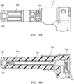
- FIGs. 5A and 5B show the central terminal 302 only partially inserted, and therefore improperly placed, in the L-shaped terminal cavity 310.
- the terminal assembly subassembly 602 shown in FIG. 3D after inspection of the central terminal 302 through the terminal viewing opening 406, is placed within a connection portion outer shield 604, thereby covering the terminal viewing opening 406.
- the center conductor terminal 702 attached to the coaxial cable is inserted within the terminal assembly 100.
- the center conductor terminal 702 is a male pin terminal that is received within the first connection portion 404 of the central terminal 302 as shown in FIG. 8A .
- the outer shield 704 of the coaxial cable 104 is attached to a connection portion outer shield 604. As highlighted in FIG.
- the insulative housing 304 defines a connection verification opening 408 and the attachment portion outer shield 310 defines first and second shield openings 802 aligned with the connection verification opening 408 that allow a human inspector or machine vision inspection system to verify the proper connection between a pin tip 708 of the center conductor terminal 702 attached to the central conductor 706 of the coaxial cable 104 and the central terminal 302.
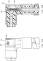
- FIGs. 9A and 9B show the center conductor terminal 702 properly seated within the first connection portion 404 of the central terminal 302. As shown in FIG. 9A , the center conductor terminal 702 is properly seated within the first connection portion 404 of the central terminal 302 when the pin tip 708 of the center conductor terminal 702 is visible within the connection verification opening 408.
- FIGs. 9A and 9B show the center conductor terminal 702 properly seated within the first connection portion 404 of the central terminal 302. As shown in FIG. 9A , the center conductor terminal 702 is properly seated within the first connection portion 404 of the central terminal 302 when the pin
- connection verification opening 408 in relation to the first connection portion 404 of the central terminal 302 allows for verification of appropriate pin tip placement of the center conductor terminal 702. If any portion of the pin tip 708 of the center conductor terminal 702 is visible in the connection verification opening 408 and the first and second shield openings 802 above the insulative housing 304, then a minimum acceptable connection interface between the center conductor terminal 702 and the central terminal 302 has been established. As shown in FIG. 10A , the pin tip 708 of the center conductor terminal 702 is not visible within the connection verification opening 408 when the center conductor terminal 702 is improperly seated within the first connection portion 404 of the central terminal 302.
- connection verification opening 408 define a through-hole allows backlighting of the connection verification opening 408 when inspecting for the pin tip 708 engagement of the center conductor terminal 702 in the first connection portion 404 of the central terminal 302 which simplifies the inspection process.
- connection verification opening 408 may be formed by stamping into the attachment portion outer shield 310 and molding the insulative housing 304 without the need for an additional manufacturing process to close the connection verification opening after inspection, e.g., no additional flap or secondary cover is needed.
- the double ended central terminal 302 described within has a female socket on each end
- other embodiments of a the double ended terminal be envisioned that have male pins or blades on each end or a combination for male and female features on each end of the double ended terminal.
- FIG. 11A illustrates another non-limiting example of an embodiment of a terminal assembly 1100.
- the embodiment is a straight two pin connector for a shielded two conductor electrical cable 1102 having a parallel wire pair or a twisted wire pair.
- pin terminals 1104 attached to the conductor of the shielded two conductor electrical cable 1102 are properly seated within the female sockets 1106 of the connector terminals 1108 when the pin terminals 1104 are visible within the connection verification openings 1110 in the terminal shield 1112.
- the size and location of the connection verification openings 1110 in relation to the female sockets 1106 of the connector terminals 1108 allows for verification of appropriate pin tip placement of the pin terminals 1104. If any portion of the pin terminal 1104 is visible in the connection verification openings 1110, then a minimum acceptable connection interface between the pin terminals 1104 and the connector terminals 1108 has been established. As shown in FIG.
- connection verification openings 1110 also allow inspection and/or measurement of the pin terminals 1104 being consistently inserted within the female sockets 1106 of the connector terminals 1108.
- terminal assembly 1100 described within has connector terminals 1108 with female sockets 1106, other embodiments of the connector terminals be envisioned that have male pins or blades.
- the techniques described herein relate to a terminal assembly, including: an insulative body having a terminal cavity formed within; a first terminal disposed within the terminal cavity; and a second terminal having an interface configured to connect with the first terminal within the terminal cavity, wherein the insulative body defines a connection verification opening extending from an outer surface of the insulative body to the terminal cavity and wherein the connection verification opening is sized, shaped, and arranged to provide visual access to verify a connection between the first and second terminals.
- connection verification opening extends through the terminal cavity to the outer surface on an opposite side of the insulative body in a direction generally perpendicular to a longitudinal axis of the terminal cavity.
- the techniques described herein relate to a terminal assembly, wherein the first terminal has a first connection portion configured to connect to the second terminal and a second connection portion configured to connect with a third corresponding mating terminal and wherein a tip of the second terminal is received in the first connection portion and is visible though the connection verification opening.
- the techniques described herein relate to a terminal assembly, wherein the insulative body also defines a terminal viewing opening distinct from the connection verification opening extending from an outer surface of the insulative body to the terminal cavity, wherein the terminal viewing opening is sized, shaped, and arranged to provide visual access to the second connection portion.
- the techniques described herein relate to a terminal assembly, wherein the terminal viewing opening is covered by a conductive shield when the terminal assembly is fully assembled.
- the techniques described herein relate to a terminal assembly, wherein the insulative body is disposed within a conductive shield defining a first shield opening through the conductive shield that is aligned with the connection verification opening and sized, shaped, and arranged to provide visual access to verify the connection between the first and second terminals.
- the techniques described herein relate to a terminal assembly, wherein the conductive shield defines a second shield opening through the conductive shield located opposite the first shield opening and wherein the second shield opening is aligned with the connection verification opening and the first shield opening and is sized, shaped, and arranged to provide visual access to verify the connection between the first and second terminals.
- the techniques described herein relate to a terminal assembly, wherein the first and second connection portions each include a female socket.
- the techniques described herein relate to a terminal assembly, wherein a first mating axis of the first connection portion is generally perpendicular to a second mating axis of the second connection portion.
- the techniques described herein relate to a terminal assembly, wherein a first mating axis of the first connection portion is generally parallel to a second mating axis of the second connection portion.
- the techniques described herein relate to a terminal assembly, wherein the terminal assembly is configured to terminate a coaxial cable.
- the techniques described herein relate to a terminal assembly, wherein the terminal assembly is configured to terminate a shielded twisted pair cable.
- the techniques described herein relate to a method of assembling a terminal assembly, including: forming a terminal cavity within an insulative body; inserting and securing a first terminal within the terminal cavity; mating a second terminal with the first terminal within the terminal cavity, wherein the insulative body defines a connection verification opening extending from an outer surface of the insulative body to the terminal cavity and wherein the connection verification opening is sized, shaped, and arranged to provide visual access to verify a connection between the first and second terminals; and inspecting the terminal assembly through the connection verification opening to verify that the first and second terminals are properly mated by viewing a tip of the second terminal in the connection verification opening.
- the techniques described herein relate to a method, wherein the first terminal has a first connection portion configured to mate with the second terminal and a second connection portion configured to connect with a third corresponding mating terminal, wherein the insulative body defines a terminal viewing opening distinct from the connection verification opening extending from an outer surface of the insulative body to the terminal cavity and sized, shaped, and arranged to provide visual access to the second connection portion, and wherein the method further includes: inspecting the terminal assembly to verify that the second connection portion is visible in the terminal viewing opening prior to mating the second terminal with the first terminal; and covering the terminal viewing opening with a conductive shield.
- the techniques described herein relate to a method, wherein a first mating axis of the first connection portion is generally perpendicular to a second mating axis of the second connection portion.
- the techniques described herein relate to a method, wherein a first mating axis of the first connection portion is generally parallel to a second mating axis of the second connection portion.
- the techniques described herein relate to a method, wherein the method further includes: inserting the insulative body within a conductive shield defining a first shield opening through the conductive shield that is aligned with the connection verification opening and sized, shaped, and arranged to provide visual access to a tip of the second terminal to verify the connection between the first and second terminals and also defining a second shield opening through the conductive shield located opposite the first shield opening, wherein the second shield opening is aligned with the connection verification opening and the first shield opening and is sized, shaped, and arranged to provide visual access to the tip of the second terminal to verify the connection between the first and second terminals.
- the techniques described herein relate to a method of assembling a terminal assembly, including: forming a terminal cavity within an insulative body via an injection molding process using a core that is stabilized by at least two guide pins, wherein the at least two guide pins form a terminal viewing opening extending from an outer surface of the insulative body to the terminal cavity; inserting and securing a first terminal within the terminal cavity, wherein the first terminal has a first connection portion configured to connect with a second terminal and a second connection portion configured to connect with a third terminal; and inspecting the terminal assembly to verify that the second connection portion is visible through the terminal viewing opening.
- the techniques described herein relate to a method, wherein the at least two guide pins form the terminal viewing opening such that the opening extends through the terminal cavity to the outer surface on opposite sides of the insulative body.
- the techniques described herein relate to a method, wherein the core is stabilized by four or more guide pins that form four or more openings extending through the terminal cavity to the outer surface on opposite sides of the insulative body.
- 'one or more' includes a function being performed by one element, a function being performed by more than one element, e.g., in a distributed fashion, several functions being performed by one element, several functions being performed by several elements, or any combination of the above.
- first, second, etc. are, in some instances, used herein to describe various elements, these elements should not be limited by these terms. These terms are only used to distinguish one element from another.
- a first contact could be termed a second contact, and, similarly, a second contact could be termed a first contact, without departing from the scope of the various described embodiments.
- the first contact and the second contact are both contacts, but they are not the same contact.
- the term “if' is, optionally, construed to mean “when” or “upon” or “in response to determining” or “in response to detecting,” depending on the context.
- the phrase “if it is determined” or “if [a stated condition or event] is detected” is, optionally, construed to mean “upon determining” or “in response to determining” or “upon detecting [the stated condition or event]” or “in response to detecting [the stated condition or event],” depending on the context.
Landscapes
- Engineering & Computer Science (AREA)
- Manufacturing & Machinery (AREA)
- Details Of Connecting Devices For Male And Female Coupling (AREA)
Abstract
A terminal assembly (100, 1100) includes an insulative body (304) having a terminal cavity (410) formed within, a first terminal (302, 1104) is disposed within the terminal cavity (410), and a second terminal (702, 1108) having an interface configured to connect with the first terminal (302, 1104) within the terminal cavity (410). The insulative body (304) defines an opening (408) extending from an outer surface of the insulative body (304) to the terminal cavity (410). The opening (408) is sized, shaped, and arranged to provide visual access to verify a connection between the first and second terminals (302, 702, 1104, 1108). Several methods of assembling such a terminal assembly (100, 1100) are also disclosed.
Description
- This disclosure is directed to a terminal assembly, particularly to a terminal assembly having one or more terminal inspection ports which allows visual confirmation of proper seating and/or connection of electrical terminals within the connector.
- Terminal assemblies may have a blind plug and socket connection between a male plug terminal and a female socket terminal within an insulator or connector housing. Blind plug and socket connections cause a risk of lower quality due to a partial or improper plugging of the male terminal within the female socket terminal which could lead to poor or intermittent performance of the connector. Some previous connector designs had a slot configured for viewing the interface between the male and female terminals along the terminal axis. However, this causes a long sight path which could obscure the view of the plug and socket connection and therefore render it difficult to clearly inspect the connection.
- In some aspects, the techniques described herein relate to a terminal assembly, including: an insulative body having a terminal cavity formed within; a first terminal disposed within the terminal cavity; and a second terminal having an interface configured to connect with the first terminal within the terminal cavity, wherein the insulative body defines a connection verification opening extending from an outer surface of the insulative body to the terminal cavity and wherein the connection verification opening is sized, shaped, and arranged to provide visual access to verify a connection between the first and second terminals.
- In some aspects, the techniques described herein relate to a method of assembling a terminal assembly, including: forming a terminal cavity within an insulative body; inserting and securing a first terminal within the terminal cavity; mating a second terminal with the first terminal within the terminal cavity, wherein the insulative body defines a connection verification opening extending from an outer surface of the insulative body to the terminal cavity and wherein the connection verification opening is sized, shaped, and arranged to provide visual access to verify a connection between the first and second terminals; and inspecting the terminal assembly through the connection verification opening to verify that the first and second terminals are properly mated by viewing a tip of the second terminal in the connection verification opening.
- In some aspects, the techniques described herein relate to a method of assembling a terminal assembly, including: forming a terminal cavity within an insulative body via an injection molding process using a core that is stabilized by at least two guide pins, wherein the at least two guide pins form a terminal viewing opening extending from an outer surface of the insulative body to the terminal cavity; inserting and securing a first terminal within the terminal cavity, wherein the first terminal has a first connection portion configured to connect with a second terminal and a second connection portion configured to connect with a third terminal; and inspecting the terminal assembly to verify that the second connection portion is visible through the terminal viewing opening.
- The present invention will now be described by way of example with reference to the accompanying drawings, in which:
-
FIG. 1 illustrates an isometric view of a terminal assembly according to some embodiments. -
FIG. 2A illustrates side views of two variants of the terminal assembly ofFIG. 1 according to some embodiments. -
FIG. 2B illustrates a side view of the terminal assembly ofFIG. 2A contained in a connector housing according to some embodiments. -
FIGs. 3A to 3D illustrate a sequence of forming a connector subassembly by inserting a central terminal within an insulator of the terminal assembly ofFIG. 1 according to some embodiments. -
FIG. 4A is a side view of the insulator of the terminal assembly ofFIG. 1 showing the central terminal in the proper location according to some embodiments. -
FIG. 4B is a cross section view of the insulator of the terminal assembly ofFIG. 1 showing the central terminal in the proper location according to some embodiments. -
FIG. 5A is a side view of the insulator of the terminal assembly ofFIG. 1 showing the central terminal in an improper location according to some embodiments. -
FIG. 5B is a cross section view of the insulator of the terminal assembly ofFIG. 1 showing the central terminal in the improper location according to some embodiments. -
FIG. 6 illustrates an assembly step of inserting the connector subassembly ofFIG 3D within a shield terminal portion of the terminal assembly ofFIG. 1 according to some embodiments. -
FIGs. 7 ,8A, and 8B illustrate an assembly sequence of inserting a male plug terminal into the central terminal in the insulator of the terminal assembly ofFIG. 1 according to some embodiments. -
FIG. 9A is a side view of the terminal assembly ofFIG. 1 showing male plug terminal in the proper location according to some embodiments. -
FIG. 9B is a cross section view of the terminal assembly ofFIG. 1 showing the male plug terminal in the proper location according to some embodiments. -
FIG. 10A is a side view of the terminal assembly ofFIG. 1 showing the central terminal and the male plug terminal in the proper location according to some embodiments. -
FIG. 10B is a cross section view of the terminal assembly ofFIG. 1 showing the central terminal and the male plug terminal in the proper location according to some embodiments. -
FIG. 11A illustrates a top view of another terminal assembly according to some embodiments having two female terminals and two male plug terminals. -
FIG. 11B is an isolated top view of the terminal assembly ofFIG. 11A showing one of the male plug terminals properly mated with one of the female terminals according to some embodiments. -
FIG. 11C is an isolated top view of the terminal assembly ofFIG. 11A showing one of the male plug terminals properly mated with one of the female terminals according to some embodiments. -
FIG. 12 is a top view of the terminal assembly ofFIG. 11A showing an acceptable offset between the two male terminals when mated with the two female terminals according to some embodiments. -
FIGs. 1, 2A, and 2B illustrate non-limiting examples of embodiments ofterminal assemblies 100. In these examples, the embodiments are right-angled coaxial terminal assemblies. Theseterminal assemblies 100 each have anattachment portion 102 that is attached to acoaxial cable 104 by aferrule 106 crimped around theattachment portion 102. Theterminal assemblies 100 also have aconnection portion 108 that is generally arranged perpendicularly with theattachment portion 102 and that is configured to interconnect with a corresponding coaxial mating connector (now shown). As shown inFIGs 2A and 2B , the length of theconnection portion 108 may be varied to allowmultiple terminal assemblies 100 to be accommodated in asingle connector housing 202 as shown inFIG. 2B The attachment andconnection portions FIG. 7 ) of thecoaxial cable 104 to provide an electromagnetic shield for thecenter conductor terminal 702 attached to the central conductor 706 (seeFIG. 7 ) of thecoaxial cable 104 in theterminal assemblies 100. Thehousing 202 has several cavities that are configured to receive theterminal assemblies 100 and retaining features 204 configured to secure theterminal assemblies 100 within the cavities of thehousing 202. Thehousing 202 may also be configured to receive the corresponding coaxial mating connectors and secure them to theterminal assemblies 100. -
FIGs. 3A to 3D illustrate a sequence of forming a connector subassembly 300 by inserting acentral terminal 302 within aninsulator 304 of theterminal assembly 100 ofFIG. 1 according to some embodiments. In the illustrated example thecentral terminal 302 is a double ended female socket terminal, however alternative embodiments may be envisioned that employ different types of central terminals. Theinsulator 304 is contained within the attachment andconnection portions FIG. 3A illustrates the L-shapedinsulative housing 304 which has first andsecond ends opening 310 configured to receive thecentral terminal 302 into an L-shaped cavity 410 (seeFIG. 4B ) within theinsulator 304. As shown inFIG. 3B , thecentral terminal 302, which is configured to terminate a central conductor 706 (seeFIG. 7 ) of thecoaxial cable 104, is inserted within theopening 310 in theinsulative housing 304. Thecentral terminal 302 may be secured within thehousing 304 by anindentation 312 using a cold-forming process described inU.S. Patent No. 10,680,358 B2 FIG. 3C. FIG. 3D shows theattachment portion 102 being placed over part of theconnector subassembly 300. The attachment portion illustrated here is configured to open and clamp around theconnector subassembly 300. Alternative embodiments may be envisioned in which the attachment portion slides over theconnector subassembly 300. -
FIGs. 4A and 4B show thecentral terminal 302 properly placed in the L-shapedterminal cavity 310. Thecentral terminal 302 has asecond connection portion 402 configured to connect to a central terminal attached to the central conductor of the coaxial cable and afirst connection portion 404 that is configured to connect with a mating terminal of a corresponding coaxial connector (not shown). When thecentral terminal 302 is fully inserted in the L-shapedterminal cavity 310, thesecond connection portion 402 is visible within aterminal viewing opening 406 extending through theinsulative housing 304 from an outer surface on one side of theinsulative housing 304 to the outer surface on another side of theinsulative housing 304. Theterminal viewing opening 406 allows visual inspection and verification of the proper location of thesecond connection portion 402 within theinsulative housing 304 by a human inspector or machine vision inspection system. By extending theterminal viewing opening 406 through theinsulative housing 304, theterminal viewing opening 406 may be backlighted to provide a better view of thesecond connection portion 402 during the inspection process. Theinsulative housing 304 also defines aconnection verification opening 408 which will be discussed later.FIGs. 5A and 5B show thecentral terminal 302 only partially inserted, and therefore improperly placed, in the L-shapedterminal cavity 310. - As shown in
FIG. 6 , theterminal assembly subassembly 602 shown inFIG. 3D , after inspection of thecentral terminal 302 through theterminal viewing opening 406, is placed within a connection portionouter shield 604, thereby covering theterminal viewing opening 406. - As shown in
FIG. 7 , thecenter conductor terminal 702 attached to the coaxial cable is inserted within theterminal assembly 100. Thecenter conductor terminal 702 is a male pin terminal that is received within thefirst connection portion 404 of thecentral terminal 302 as shown inFIG. 8A . Theouter shield 704 of thecoaxial cable 104 is attached to a connection portionouter shield 604. As highlighted inFIG. 8B , theinsulative housing 304 defines aconnection verification opening 408 and the attachment portionouter shield 310 defines first andsecond shield openings 802 aligned with theconnection verification opening 408 that allow a human inspector or machine vision inspection system to verify the proper connection between apin tip 708 of thecenter conductor terminal 702 attached to thecentral conductor 706 of thecoaxial cable 104 and thecentral terminal 302.FIGs. 9A and 9B show thecenter conductor terminal 702 properly seated within thefirst connection portion 404 of thecentral terminal 302. As shown inFIG. 9A , thecenter conductor terminal 702 is properly seated within thefirst connection portion 404 of thecentral terminal 302 when thepin tip 708 of thecenter conductor terminal 702 is visible within theconnection verification opening 408.FIGs. 10A and 10B show thecenter conductor terminal 702 improperly seated within thefirst connection portion 404 of thecentral terminal 302. The size and location of theconnection verification opening 408 in relation to thefirst connection portion 404 of thecentral terminal 302 allows for verification of appropriate pin tip placement of thecenter conductor terminal 702. If any portion of thepin tip 708 of thecenter conductor terminal 702 is visible in theconnection verification opening 408 and the first andsecond shield openings 802 above theinsulative housing 304, then a minimum acceptable connection interface between thecenter conductor terminal 702 and thecentral terminal 302 has been established. As shown inFIG. 10A , thepin tip 708 of thecenter conductor terminal 702 is not visible within theconnection verification opening 408 when thecenter conductor terminal 702 is improperly seated within thefirst connection portion 404 of thecentral terminal 302. - Having the
connection verification opening 408 define a through-hole allows backlighting of theconnection verification opening 408 when inspecting for thepin tip 708 engagement of thecenter conductor terminal 702 in thefirst connection portion 404 of thecentral terminal 302 which simplifies the inspection process. - The
connection verification opening 408 may be formed by stamping into the attachment portionouter shield 310 and molding theinsulative housing 304 without the need for an additional manufacturing process to close the connection verification opening after inspection, e.g., no additional flap or secondary cover is needed. - While the double ended
central terminal 302 described within has a female socket on each end, other embodiments of a the double ended terminal be envisioned that have male pins or blades on each end or a combination for male and female features on each end of the double ended terminal. -
FIG. 11A illustrates another non-limiting example of an embodiment of aterminal assembly 1100. In this example, the embodiment is a straight two pin connector for a shielded two conductorelectrical cable 1102 having a parallel wire pair or a twisted wire pair. - As shown in
FIG. 11B ,pin terminals 1104 attached to the conductor of the shielded two conductorelectrical cable 1102 are properly seated within thefemale sockets 1106 of theconnector terminals 1108 when thepin terminals 1104 are visible within theconnection verification openings 1110 in theterminal shield 1112. The size and location of theconnection verification openings 1110 in relation to thefemale sockets 1106 of theconnector terminals 1108 allows for verification of appropriate pin tip placement of thepin terminals 1104. If any portion of thepin terminal 1104 is visible in theconnection verification openings 1110, then a minimum acceptable connection interface between thepin terminals 1104 and theconnector terminals 1108 has been established. As shown inFIG. 11C , thepin terminals 1104 are not visible within theconnection verification openings 1110 when thepin terminals 1104 are improperly seated within thefemale sockets 1106 of theconnector terminals 1108. As shown inFIG. 12 , theconnection verification openings 1110 also allow inspection and/or measurement of thepin terminals 1104 being consistently inserted within thefemale sockets 1106 of theconnector terminals 1108. - While the
terminal assembly 1100 described within hasconnector terminals 1108 withfemale sockets 1106, other embodiments of the connector terminals be envisioned that have male pins or blades. - While a right-angled coaxial connector assembly and a straight two pin connector assembly for a shielded two conductor electrical cable has been described herein, other embodiments may be different connector configurations, for example connectors having different angles between the cable and the connector or that may be used with other cable types, e.g., twin-axial or unshielded conductor cables, may also be envisioned.
- In some aspects, the techniques described herein relate to a terminal assembly, including: an insulative body having a terminal cavity formed within; a first terminal disposed within the terminal cavity; and a second terminal having an interface configured to connect with the first terminal within the terminal cavity, wherein the insulative body defines a connection verification opening extending from an outer surface of the insulative body to the terminal cavity and wherein the connection verification opening is sized, shaped, and arranged to provide visual access to verify a connection between the first and second terminals.
- In some aspects, the techniques described herein relate to a terminal assembly, wherein the connection verification opening extends through the terminal cavity to the outer surface on an opposite side of the insulative body in a direction generally perpendicular to a longitudinal axis of the terminal cavity.
- In some aspects, the techniques described herein relate to a terminal assembly, wherein the first terminal has a first connection portion configured to connect to the second terminal and a second connection portion configured to connect with a third corresponding mating terminal and wherein a tip of the second terminal is received in the first connection portion and is visible though the connection verification opening.
- In some aspects, the techniques described herein relate to a terminal assembly, wherein the insulative body also defines a terminal viewing opening distinct from the connection verification opening extending from an outer surface of the insulative body to the terminal cavity, wherein the terminal viewing opening is sized, shaped, and arranged to provide visual access to the second connection portion.
- In some aspects, the techniques described herein relate to a terminal assembly, wherein the terminal viewing opening is covered by a conductive shield when the terminal assembly is fully assembled.
- In some aspects, the techniques described herein relate to a terminal assembly, wherein the insulative body is disposed within a conductive shield defining a first shield opening through the conductive shield that is aligned with the connection verification opening and sized, shaped, and arranged to provide visual access to verify the connection between the first and second terminals.
- In some aspects, the techniques described herein relate to a terminal assembly, wherein the conductive shield defines a second shield opening through the conductive shield located opposite the first shield opening and wherein the second shield opening is aligned with the connection verification opening and the first shield opening and is sized, shaped, and arranged to provide visual access to verify the connection between the first and second terminals.
- In some aspects, the techniques described herein relate to a terminal assembly, wherein the first and second connection portions each include a female socket.
- In some aspects, the techniques described herein relate to a terminal assembly, wherein a first mating axis of the first connection portion is generally perpendicular to a second mating axis of the second connection portion.
- In some aspects, the techniques described herein relate to a terminal assembly, wherein a first mating axis of the first connection portion is generally parallel to a second mating axis of the second connection portion.
- In some aspects, the techniques described herein relate to a terminal assembly, wherein the terminal assembly is configured to terminate a coaxial cable.
- In some aspects, the techniques described herein relate to a terminal assembly, wherein the terminal assembly is configured to terminate a shielded twisted pair cable.
- In some aspects, the techniques described herein relate to a method of assembling a terminal assembly, including: forming a terminal cavity within an insulative body; inserting and securing a first terminal within the terminal cavity; mating a second terminal with the first terminal within the terminal cavity, wherein the insulative body defines a connection verification opening extending from an outer surface of the insulative body to the terminal cavity and wherein the connection verification opening is sized, shaped, and arranged to provide visual access to verify a connection between the first and second terminals; and inspecting the terminal assembly through the connection verification opening to verify that the first and second terminals are properly mated by viewing a tip of the second terminal in the connection verification opening.
- In some aspects, the techniques described herein relate to a method, wherein the first terminal has a first connection portion configured to mate with the second terminal and a second connection portion configured to connect with a third corresponding mating terminal, wherein the insulative body defines a terminal viewing opening distinct from the connection verification opening extending from an outer surface of the insulative body to the terminal cavity and sized, shaped, and arranged to provide visual access to the second connection portion, and wherein the method further includes: inspecting the terminal assembly to verify that the second connection portion is visible in the terminal viewing opening prior to mating the second terminal with the first terminal; and covering the terminal viewing opening with a conductive shield.
- In some aspects, the techniques described herein relate to a method, wherein a first mating axis of the first connection portion is generally perpendicular to a second mating axis of the second connection portion.
- In some aspects, the techniques described herein relate to a method, wherein a first mating axis of the first connection portion is generally parallel to a second mating axis of the second connection portion.
- In some aspects, the techniques described herein relate to a method, wherein the method further includes: inserting the insulative body within a conductive shield defining a first shield opening through the conductive shield that is aligned with the connection verification opening and sized, shaped, and arranged to provide visual access to a tip of the second terminal to verify the connection between the first and second terminals and also defining a second shield opening through the conductive shield located opposite the first shield opening, wherein the second shield opening is aligned with the connection verification opening and the first shield opening and is sized, shaped, and arranged to provide visual access to the tip of the second terminal to verify the connection between the first and second terminals.
- In some aspects, the techniques described herein relate to a method of assembling a terminal assembly, including: forming a terminal cavity within an insulative body via an injection molding process using a core that is stabilized by at least two guide pins, wherein the at least two guide pins form a terminal viewing opening extending from an outer surface of the insulative body to the terminal cavity; inserting and securing a first terminal within the terminal cavity, wherein the first terminal has a first connection portion configured to connect with a second terminal and a second connection portion configured to connect with a third terminal; and inspecting the terminal assembly to verify that the second connection portion is visible through the terminal viewing opening.
- In some aspects, the techniques described herein relate to a method, wherein the at least two guide pins form the terminal viewing opening such that the opening extends through the terminal cavity to the outer surface on opposite sides of the insulative body.
- In some aspects, the techniques described herein relate to a method, wherein the core is stabilized by four or more guide pins that form four or more openings extending through the terminal cavity to the outer surface on opposite sides of the insulative body.
- While the invention has been described with reference to an exemplary embodiment(s), it will be understood by those skilled in the art that various changes may be made, and equivalents may be substituted for elements thereof without departing from the scope of the invention. In addition, many modifications may be made to adapt a particular situation or material to the teachings of the invention without departing from the essential scope thereof. Therefore, it is intended that the invention is not limited to the disclosed embodiment(s), but that the invention will include all embodiments falling within the scope of the appended claims.
- As used herein, 'one or more' includes a function being performed by one element, a function being performed by more than one element, e.g., in a distributed fashion, several functions being performed by one element, several functions being performed by several elements, or any combination of the above.
- It will also be understood that, although the terms first, second, etc. are, in some instances, used herein to describe various elements, these elements should not be limited by these terms. These terms are only used to distinguish one element from another. For example, a first contact could be termed a second contact, and, similarly, a second contact could be termed a first contact, without departing from the scope of the various described embodiments. The first contact and the second contact are both contacts, but they are not the same contact.
- The terminology used in the description of the various described embodiments herein is for the purpose of describing particular embodiments only and is not intended to be limiting. As used in the description of the various described embodiments and the appended claims, the singular forms "a", "an" and "the" are intended to include the plural forms as well, unless the context clearly indicates otherwise. It will also be understood that the term "and/or" as used herein refers to and encompasses any and all possible combinations of one or more of the associated listed items. It will be further understood that the terms "includes," "including," "comprises," and/or "comprising," when used in this specification, specify the presence of stated features, integers, steps, operations, elements, and/or components, but do not preclude the presence or addition of one or more other features, integers, steps, operations, elements, components, and/or groups thereof.
- As used herein, the term "if' is, optionally, construed to mean "when" or "upon" or "in response to determining" or "in response to detecting," depending on the context. Similarly, the phrase "if it is determined" or "if [a stated condition or event] is detected" is, optionally, construed to mean "upon determining" or "in response to determining" or "upon detecting [the stated condition or event]" or "in response to detecting [the stated condition or event]," depending on the context.
- Additionally, while terms of ordinance or orientation may be used herein these elements should not be limited by these terms. All terms of ordinance or orientation, unless stated otherwise, are used for purposes distinguishing one element from another, and do not denote any particular order, order of operations, direction or orientation unless stated otherwise.
Claims (15)
- A terminal assembly (100, 1100), comprising:an insulative body (304) having a terminal cavity (410) formed within;a first terminal (302, 1104) disposed within the terminal cavity (410); anda second terminal (702, 1108) having an interface configured to connect with the first terminal (302) within the terminal cavity (410), wherein the insulative body (304) defines a connection verification opening (408) extending from an outer surface of the insulative body (304) to the terminal cavity (410) and wherein the connection verification opening (408) is sized, shaped, and arranged to provide visual access to verify a connection between the first and second terminals (302, 702, 1104, 1108).
- The terminal assembly (100, 1100) according to claim 1, wherein the connection verification opening (408, 1110) extends through the terminal cavity (410) to the outer surface on an opposite side of the insulative body (304) in a direction generally perpendicular to a longitudinal axis of the terminal cavity (410).
- The terminal assembly (100) according to claim 1 or 2, wherein the first terminal (302) has a first connection portion (404) configured to connect to the second terminal (702) and a second connection portion (402) configured to connect with a third corresponding mating terminal and wherein a tip (708) of the second terminal (702) is received in the first connection portion (404) and is visible though the connection verification opening (408).
- The terminal assembly (100) according to claim 3, wherein the insulative body (304) also defines a terminal viewing opening (406) distinct from the connection verification opening (408) extending from an outer surface of the insulative body (304) to the terminal cavity (410), wherein the terminal viewing opening (406) is sized, shaped, and arranged to provide visual access to the second connection portion (402).
- The terminal assembly (100) according to claim 4, wherein the terminal viewing opening (406) is covered by a conductive shield (604) when the terminal assembly (100) is fully assembled.
- The terminal assembly (100, 1100) according to any one of claims 3 to 5, wherein the insulative body (304) is disposed within a conductive shield (310, 1112) defining a first shield opening (802, 1110) through the conductive shield (310, 1112) that is aligned with the connection verification opening (408) and sized, shaped, and arranged to provide visual access to verify the connection between the first and second terminals (302, 702, 1104, 1108).
- The terminal assembly (100, 1100) according to claim 6, wherein the conductive shield (310) defines a second shield opening (802, 1110) through the conductive shield (310) located opposite the first shield opening (802, 1110) and wherein the second shield opening (802, 1110) is aligned with the connection verification opening (408) and the first shield opening and is sized, shaped, and arranged to provide visual access to verify the connection between the first and second terminals (302, 702, 1104, 1108).
- The terminal assembly (100) according to claim 7, wherein the first and second connection portions (404, 402) each comprise a female socket.
- The terminal assembly (100) according to claim 7 or 8, wherein a first mating axis of the first connection portion (404) is generally perpendicular to a second mating axis of the second connection portion (402).
- The terminal assembly (1100) according to any one of claims 7 to 9, wherein a first mating axis of the first connection portion (1108) is generally parallel to a second mating axis of the second connection portion (1104).
- The terminal assembly (100) according to any one of the preceding claims, wherein the terminal assembly (100) is configured to terminate a coaxial cable (104).
- The terminal assembly (1100) according to claim 1, wherein the terminal assembly (1100) is configured to terminate a shielded twisted pair cable (1102).
- A method of assembling a terminal assembly (100, 1100), comprising:forming a terminal cavity (410) within an insulative body (304);inserting and securing a first terminal (302, 1104) within the terminal cavity (410);mating a second terminal (702, 1108) with the first terminal (302, 1104) within the terminal cavity (410), wherein the insulative body (304) defines a connection verification opening (408) extending from an outer surface of the insulative body to the terminal cavity and wherein the connection verification opening (408) is sized, shaped, and arranged to provide visual access to verify a connection between the first and second terminals (302, 702, 1104, 1108); andinspecting the terminal assembly (100, 1100) through the connection verification opening (408) to verify that the first and second terminals (302, 702, 1104, 1108) are properly mated by viewing a tip of the second terminal (702, 1108) in the connection verification opening (408).
- The method according to claim 13, wherein the first terminal (302) has a first connection portion (404) configured to mate with the second terminal (702) and a second connection portion (402) configured to connect with a third corresponding mating terminal, wherein the insulative body (304) defines a terminal viewing opening (406) distinct from the connection verification opening (408) extending from an outer surface of the insulative body (304) to the terminal cavity (410) and sized, shaped, and arranged to provide visual access to the second connection portion (402), and wherein the method further comprises:inspecting the terminal assembly (100) to verify that the second connection portion (402) is visible in the terminal viewing opening (406) prior to mating the second terminal (702) with the first terminal (302); andcovering the terminal viewing opening (406) with a conductive shield (310).
- The method according to claim 14, wherein the method further comprises:
inserting the insulative body (304) within a conductive shield (310, 1112) defining a first shield opening (802, 1110) through the conductive shield (310, 1112) that is aligned with the connection verification opening (408) and sized, shaped, and arranged to provide visual access to a tip (708) of the second terminal (702, 1108) to verify the connection between the first and second terminals (302, 702, 1104, 1108) and also defining a second shield opening (802, 1110) through the conductive shield (310, 1112) located opposite the first shield opening (802, 1110), wherein the second shield opening (802, 1110) is aligned with the connection verification opening (408) and the first shield opening (802, 1110) and is sized, shaped, and arranged to provide visual access to the tip of the second terminal (702, 1108) to verify the connection between the first and second terminals (302, 702, 1104, 1108).
Applications Claiming Priority (2)
| Application Number | Priority Date | Filing Date | Title |
|---|---|---|---|
| US202363526220P | 2023-07-12 | 2023-07-12 | |
| US18/383,334 US20250023279A1 (en) | 2023-07-12 | 2023-10-24 | Terminal assembly with terminal inspection port and methods of assembling same |
Publications (1)
| Publication Number | Publication Date |
|---|---|
| EP4492578A1 true EP4492578A1 (en) | 2025-01-15 |
Family
ID=91804067
Family Applications (1)
| Application Number | Title | Priority Date | Filing Date |
|---|---|---|---|
| EP24186154.1A Pending EP4492578A1 (en) | 2023-07-12 | 2024-07-03 | Terminal assembly with terminal inspection port and methods of assembling same |
Country Status (3)
| Country | Link |
|---|---|
| US (1) | US20250023279A1 (en) |
| EP (1) | EP4492578A1 (en) |
| CN (1) | CN119315304A (en) |
Citations (6)
| Publication number | Priority date | Publication date | Assignee | Title |
|---|---|---|---|---|
| US4096627A (en) * | 1976-05-24 | 1978-06-27 | Amp Incorporated | Method of forming port hole coaxial connector |
| US20110230092A1 (en) * | 2008-10-29 | 2011-09-22 | Rosenberger Hochfrequenztechnik Gmbh & Co. Kg | Hf-angle plug connector |
| EP2053705B1 (en) * | 2007-10-23 | 2017-05-03 | Rosenberger Hochfrequenztechnik GmbH & Co. KG | Angle plug |
| US20170222368A1 (en) * | 2016-02-01 | 2017-08-03 | Delphi Technologies, Inc. | Right angled coaxial electrical connector and methods for verifying proper assembly thereof |
| US10680358B2 (en) | 2018-08-09 | 2020-06-09 | Aptiv Technologies Limited | Method for securing a terminal within a connector housing of a connector assembly and a connector assembly formed by said method |
| US10770840B1 (en) * | 2019-06-14 | 2020-09-08 | Aptiv Technologies Limited | Shielded electrical connector assembly |
Family Cites Families (5)
| Publication number | Priority date | Publication date | Assignee | Title |
|---|---|---|---|---|
| US4655534A (en) * | 1985-03-15 | 1987-04-07 | E. F. Johnson Company | Right angle coaxial connector |
| US4932898A (en) * | 1989-02-07 | 1990-06-12 | Itt Corporation | Termination system for coaxial conductor |
| US7946886B1 (en) * | 2009-12-22 | 2011-05-24 | Wealleys Technologies Co., Ltd. | Contact of coaxial cable connector |
| US8647128B2 (en) * | 2011-12-20 | 2014-02-11 | Tyco Electronics Corporation | Coaxial connector |
| DE102020116736A1 (en) * | 2020-06-25 | 2021-12-30 | Te Connectivity Germany Gmbh | Connector for a connector system, connector system and method for producing a connector system |
-
2023
- 2023-10-24 US US18/383,334 patent/US20250023279A1/en active Pending
-
2024
- 2024-07-03 EP EP24186154.1A patent/EP4492578A1/en active Pending
- 2024-07-09 CN CN202410913967.2A patent/CN119315304A/en active Pending
Patent Citations (6)
| Publication number | Priority date | Publication date | Assignee | Title |
|---|---|---|---|---|
| US4096627A (en) * | 1976-05-24 | 1978-06-27 | Amp Incorporated | Method of forming port hole coaxial connector |
| EP2053705B1 (en) * | 2007-10-23 | 2017-05-03 | Rosenberger Hochfrequenztechnik GmbH & Co. KG | Angle plug |
| US20110230092A1 (en) * | 2008-10-29 | 2011-09-22 | Rosenberger Hochfrequenztechnik Gmbh & Co. Kg | Hf-angle plug connector |
| US20170222368A1 (en) * | 2016-02-01 | 2017-08-03 | Delphi Technologies, Inc. | Right angled coaxial electrical connector and methods for verifying proper assembly thereof |
| US10680358B2 (en) | 2018-08-09 | 2020-06-09 | Aptiv Technologies Limited | Method for securing a terminal within a connector housing of a connector assembly and a connector assembly formed by said method |
| US10770840B1 (en) * | 2019-06-14 | 2020-09-08 | Aptiv Technologies Limited | Shielded electrical connector assembly |
Also Published As
| Publication number | Publication date |
|---|---|
| CN119315304A (en) | 2025-01-14 |
| US20250023279A1 (en) | 2025-01-16 |
Similar Documents
| Publication | Publication Date | Title |
|---|---|---|
| CN108701948B (en) | Right-angle coaxial electrical connector and method for verifying proper assembly of right-angle coaxial electrical connector | |
| CN113841302B (en) | Contact carrier for shielding a hybrid contact assembly and plug connector | |
| US9899760B2 (en) | Electrical connector having a metallic ferrule accommodated within a receptacle and crimped to a cable | |
| US10886668B1 (en) | Coaxial cable connector assembly | |
| US10770840B1 (en) | Shielded electrical connector assembly | |
| US9172188B2 (en) | Plug for a data and/or telecommunication cable comprising several conductors | |
| US9899775B2 (en) | Connector insert and connector for data transmission in automobiles | |
| US20130143424A1 (en) | Electrical plug connector | |
| CN101257167B (en) | Connector and a connector assembly | |
| US4494816A (en) | Coaxial cable connector | |
| US7892018B1 (en) | Electrical connector assembly with two cable loading stop elements | |
| US7070440B1 (en) | Coaxial cable insulation displacement connector | |
| US20200313375A1 (en) | Self shorting connector | |
| JP2023072680A (en) | Contact arrangement for coaxial plug and multiple contact arrangement | |
| US20250023279A1 (en) | Terminal assembly with terminal inspection port and methods of assembling same | |
| CN118249100A (en) | Connector components | |
| US11462342B2 (en) | Cable harness assembly with a shielded twisted pair cable | |
| US6517388B1 (en) | Line connecter with permanent or temporary screw clamp | |
| EP4411992A1 (en) | Right angled coaxial electrical connector and method of forming same | |
| EP4723390A1 (en) | Electrical connector having contacts with polarizing features | |
| HK40065410B (en) | Self shorting connector | |
| CN121216177A (en) | Second electrical connector and connector assembly | |
| HK40065410A (en) | Self shorting connector |
Legal Events
| Date | Code | Title | Description |
|---|---|---|---|
| PUAI | Public reference made under article 153(3) epc to a published international application that has entered the european phase |
Free format text: ORIGINAL CODE: 0009012 |
|
| STAA | Information on the status of an ep patent application or granted ep patent |
Free format text: STATUS: THE APPLICATION HAS BEEN PUBLISHED |
|
| AK | Designated contracting states |
Kind code of ref document: A1 Designated state(s): AL AT BE BG CH CY CZ DE DK EE ES FI FR GB GR HR HU IE IS IT LI LT LU LV MC ME MK MT NL NO PL PT RO RS SE SI SK SM TR |
|
| STAA | Information on the status of an ep patent application or granted ep patent |
Free format text: STATUS: REQUEST FOR EXAMINATION WAS MADE |
|
| 17P | Request for examination filed |
Effective date: 20250603 |