EP4492561A1 - Battery, and method for manufacturing battery - Google Patents
Battery, and method for manufacturing battery Download PDFInfo
- Publication number
- EP4492561A1 EP4492561A1 EP22930924.0A EP22930924A EP4492561A1 EP 4492561 A1 EP4492561 A1 EP 4492561A1 EP 22930924 A EP22930924 A EP 22930924A EP 4492561 A1 EP4492561 A1 EP 4492561A1
- Authority
- EP
- European Patent Office
- Prior art keywords
- recess
- joint part
- current collecting
- collecting tab
- dimension
- Prior art date
- Legal status (The legal status is an assumption and is not a legal conclusion. Google has not performed a legal analysis and makes no representation as to the accuracy of the status listed.)
- Pending
Links
Images


Classifications
-
- H—ELECTRICITY
- H01—ELECTRIC ELEMENTS
- H01M—PROCESSES OR MEANS, e.g. BATTERIES, FOR THE DIRECT CONVERSION OF CHEMICAL ENERGY INTO ELECTRICAL ENERGY
- H01M50/00—Constructional details or processes of manufacture of the non-active parts of electrochemical cells other than fuel cells, e.g. hybrid cells
- H01M50/50—Current conducting connections for cells or batteries
- H01M50/531—Electrode connections inside a battery casing
- H01M50/533—Electrode connections inside a battery casing characterised by the shape of the leads or tabs
-
- B—PERFORMING OPERATIONS; TRANSPORTING
- B23—MACHINE TOOLS; METAL-WORKING NOT OTHERWISE PROVIDED FOR
- B23K—SOLDERING OR UNSOLDERING; WELDING; CLADDING OR PLATING BY SOLDERING OR WELDING; CUTTING BY APPLYING HEAT LOCALLY, e.g. FLAME CUTTING; WORKING BY LASER BEAM
- B23K20/00—Non-electric welding by applying impact or other pressure, with or without the application of heat, e.g. cladding or plating
- B23K20/10—Non-electric welding by applying impact or other pressure, with or without the application of heat, e.g. cladding or plating making use of vibrations, e.g. ultrasonic welding
-
- H—ELECTRICITY
- H01—ELECTRIC ELEMENTS
- H01M—PROCESSES OR MEANS, e.g. BATTERIES, FOR THE DIRECT CONVERSION OF CHEMICAL ENERGY INTO ELECTRICAL ENERGY
- H01M50/00—Constructional details or processes of manufacture of the non-active parts of electrochemical cells other than fuel cells, e.g. hybrid cells
- H01M50/10—Primary casings; Jackets or wrappings
- H01M50/172—Arrangements of electric connectors penetrating the casing
- H01M50/174—Arrangements of electric connectors penetrating the casing adapted for the shape of the cells
- H01M50/176—Arrangements of electric connectors penetrating the casing adapted for the shape of the cells for prismatic or rectangular cells
-
- H—ELECTRICITY
- H01—ELECTRIC ELEMENTS
- H01M—PROCESSES OR MEANS, e.g. BATTERIES, FOR THE DIRECT CONVERSION OF CHEMICAL ENERGY INTO ELECTRICAL ENERGY
- H01M50/00—Constructional details or processes of manufacture of the non-active parts of electrochemical cells other than fuel cells, e.g. hybrid cells
- H01M50/50—Current conducting connections for cells or batteries
- H01M50/531—Electrode connections inside a battery casing
- H01M50/534—Electrode connections inside a battery casing characterised by the material of the leads or tabs
-
- H—ELECTRICITY
- H01—ELECTRIC ELEMENTS
- H01M—PROCESSES OR MEANS, e.g. BATTERIES, FOR THE DIRECT CONVERSION OF CHEMICAL ENERGY INTO ELECTRICAL ENERGY
- H01M50/00—Constructional details or processes of manufacture of the non-active parts of electrochemical cells other than fuel cells, e.g. hybrid cells
- H01M50/50—Current conducting connections for cells or batteries
- H01M50/531—Electrode connections inside a battery casing
- H01M50/536—Electrode connections inside a battery casing characterised by the method of fixing the leads to the electrodes, e.g. by welding
-
- H—ELECTRICITY
- H01—ELECTRIC ELEMENTS
- H01M—PROCESSES OR MEANS, e.g. BATTERIES, FOR THE DIRECT CONVERSION OF CHEMICAL ENERGY INTO ELECTRICAL ENERGY
- H01M50/00—Constructional details or processes of manufacture of the non-active parts of electrochemical cells other than fuel cells, e.g. hybrid cells
- H01M50/50—Current conducting connections for cells or batteries
- H01M50/531—Electrode connections inside a battery casing
- H01M50/538—Connection of several leads or tabs of wound or folded electrode stacks
-
- H—ELECTRICITY
- H01—ELECTRIC ELEMENTS
- H01M—PROCESSES OR MEANS, e.g. BATTERIES, FOR THE DIRECT CONVERSION OF CHEMICAL ENERGY INTO ELECTRICAL ENERGY
- H01M50/00—Constructional details or processes of manufacture of the non-active parts of electrochemical cells other than fuel cells, e.g. hybrid cells
- H01M50/50—Current conducting connections for cells or batteries
- H01M50/543—Terminals
- H01M50/547—Terminals characterised by the disposition of the terminals on the cells
- H01M50/55—Terminals characterised by the disposition of the terminals on the cells on the same side of the cell
-
- H—ELECTRICITY
- H01—ELECTRIC ELEMENTS
- H01M—PROCESSES OR MEANS, e.g. BATTERIES, FOR THE DIRECT CONVERSION OF CHEMICAL ENERGY INTO ELECTRICAL ENERGY
- H01M50/00—Constructional details or processes of manufacture of the non-active parts of electrochemical cells other than fuel cells, e.g. hybrid cells
- H01M50/50—Current conducting connections for cells or batteries
- H01M50/543—Terminals
- H01M50/552—Terminals characterised by their shape
- H01M50/553—Terminals adapted for prismatic, pouch or rectangular cells
-
- H—ELECTRICITY
- H01—ELECTRIC ELEMENTS
- H01M—PROCESSES OR MEANS, e.g. BATTERIES, FOR THE DIRECT CONVERSION OF CHEMICAL ENERGY INTO ELECTRICAL ENERGY
- H01M50/00—Constructional details or processes of manufacture of the non-active parts of electrochemical cells other than fuel cells, e.g. hybrid cells
- H01M50/50—Current conducting connections for cells or batteries
- H01M50/543—Terminals
- H01M50/562—Terminals characterised by the material
-
- H—ELECTRICITY
- H01—ELECTRIC ELEMENTS
- H01M—PROCESSES OR MEANS, e.g. BATTERIES, FOR THE DIRECT CONVERSION OF CHEMICAL ENERGY INTO ELECTRICAL ENERGY
- H01M50/00—Constructional details or processes of manufacture of the non-active parts of electrochemical cells other than fuel cells, e.g. hybrid cells
- H01M50/50—Current conducting connections for cells or batteries
- H01M50/543—Terminals
- H01M50/564—Terminals characterised by their manufacturing process
- H01M50/566—Terminals characterised by their manufacturing process by welding, soldering or brazing
-
- B—PERFORMING OPERATIONS; TRANSPORTING
- B23—MACHINE TOOLS; METAL-WORKING NOT OTHERWISE PROVIDED FOR
- B23K—SOLDERING OR UNSOLDERING; WELDING; CLADDING OR PLATING BY SOLDERING OR WELDING; CUTTING BY APPLYING HEAT LOCALLY, e.g. FLAME CUTTING; WORKING BY LASER BEAM
- B23K2101/00—Articles made by soldering, welding or cutting
- B23K2101/36—Electric or electronic devices
- B23K2101/38—Conductors
-
- Y—GENERAL TAGGING OF NEW TECHNOLOGICAL DEVELOPMENTS; GENERAL TAGGING OF CROSS-SECTIONAL TECHNOLOGIES SPANNING OVER SEVERAL SECTIONS OF THE IPC; TECHNICAL SUBJECTS COVERED BY FORMER USPC CROSS-REFERENCE ART COLLECTIONS [XRACs] AND DIGESTS
- Y02—TECHNOLOGIES OR APPLICATIONS FOR MITIGATION OR ADAPTATION AGAINST CLIMATE CHANGE
- Y02E—REDUCTION OF GREENHOUSE GAS [GHG] EMISSIONS, RELATED TO ENERGY GENERATION, TRANSMISSION OR DISTRIBUTION
- Y02E60/00—Enabling technologies; Technologies with a potential or indirect contribution to GHG emissions mitigation
- Y02E60/10—Energy storage using batteries
Definitions
- Embodiments of the present invention relate generally to a battery and a manufacturing method of a battery.
- an electrode group including a positive electrode and a negative electrode is housed in an inner cavity of a container member.
- an electrode terminal is disposed in the container member.
- the electrode group includes a current collector and an active material-containing layer supported on the current collector.
- the current collector includes a current collecting tab as a part on which the active material-containing layer is not supported.
- the current collecting tab is electrically connected to the electrode terminal via a conductive material such as a lead.
- a plurality of belt-shaped portions are stacked in the current collecting tab.
- the belt-shaped portions stacked in the current collecting tab are joined to a conductive member or the like by ultrasonic welding. Specifically, the stacked belt-shaped portions of the current collecting tab and the conductive member are mutually joined by being deformed. If the belt-shaped portions and the conductive member are joined in this manner, a recess is formed in a connection part, and there may be a case where burrs are formed on a peripheral edge or the like of the recess. The burrs are protrusions occurring on the above-described peripheral edge or the like during the process of forming the recess, or a residual portion of the belt-shaped portion or the like. In the joining, it is required to reduce the formation of burrs on the peripheral edge or the like of the recess that joins the belt-shaped portion and the conductive member.
- the problem to be solved by the present invention is to provide a battery and a manufacturing method of a battery, which can reduce the formation of burrs on a peripheral edge or the like of a recess that joins a belt-shaped portion and a conductive member.
- a battery includes a container member, an electrode terminal, an electrode group, a conductive member and a joint part.
- the electrode terminal is disposed in the container member.
- the electrode group is housed in an inner cavity of the container member, and includes a current collecting tab that protrudes.
- the conductive member electrically connects the electrode terminal and the current collecting tab.
- the joint part connects the current collecting tab and the conductive member.
- the joint part includes a recess and a peripheral edge portion.
- the recess is recessed toward a side on which the conductive member is located in the current collecting tab, and a second dimension between both ends in a second direction of the recess is less than a first dimension between both ends in a first direction of the recess, the second direction crossing the first direction.
- the peripheral edge portion surrounds the recess, and a residual amount of burrs is greater in a part neighboring the recess from the first direction, than in a part neighboring the recess from the second direction.
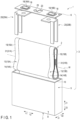
- FIG. 1 illustrates a battery 1 according to an embodiment.
- the battery 1 includes an electrode group 2 and a container member 3.
- the container member 3 includes an outer container 5 and a lid 6.
- Each of the outer container 5 and the lid 6 is made of a metal such as aluminum, an aluminum alloy, iron, copper, or stainless steel.
- a depth direction (indicated by arrow X1 and arrow X2)
- a lateral direction (indicated by arrow Y1 and arrow Y2) crossing (perpendicular or substantially perpendicular to) the depth direction
- a height direction (indicated by arrow Z1 and arrow Z2) crossing (perpendicular or substantially perpendicular to) both the depth direction and the lateral direction
- a dimension in the depth direction is less than a dimension in the lateral direction and a dimension in the height direction.
- FIG. 1 is a perspective view illustrating the individual members being exploded.
- the outer container 5 includes a bottom wall 7 and a peripheral wall 8.
- the bottom wall 7 and the peripheral wall 8 define an inner cavity 10 configured to house the electrode group 2.
- the inner cavity 10 opens to a side opposite to a side on which the bottom wall 7 is located in the height direction.
- the lid 6 is attached to the peripheral wall 8 at an end opposite to the bottom wall 7. Accordingly, the lid 6 closes the opening of the inner cavity 10 of the outer container 5.
- the lid 6 and the bottom wall 7 are opposed to each other, with the inner cavity 10 being interposed in the height direction.
- the electrode group 2 includes a pair of electrodes 13, a pair of current collectors 14, and a pair of current collecting tabs 15.
- One of the paired electrodes 13 is a positive electrode 13A, and the other of the paired electrodes 13, which is different from the positive electrode 13A, is a negative electrode 13B.
- One of the paired current collectors 14 is a positive electrode current collector 14A, and the other of the paired current collectors 14, which is different from the positive electrode current collector 14A, is a negative electrode current collector 14B.
- One of the paired current collecting tabs 15 is a positive electrode current collecting tab 15A, and the other of the paired current collecting tabs 15, which is different from the positive electrode current collecting tab 15A, is a negative electrode current collecting tab 15B.
- each of the paired current collecting tab 15 a plurality of belt-shaped portions is bundled.
- a separator (not illustrated) is interposed between the positive electrode 13A and the negative electrode 13B.
- the separator is formed of a material having an electrical insulation property, and electrically insulates the positive electrode 13A from the negative electrode 13B.
- the positive electrode current collector 14A is formed of a positive electrode current collecting foil or the like.
- a positive electrode active material-containing layer (not illustrated) is formed on a surface of the positive electrode current collector 14A.
- the positive electrode current collector 14A is, for example, an aluminum foil or an aluminum alloy foil.
- the positive electrode current collector 14A has a thickness of about 10 um to 20 um.
- the positive electrode active material-containing layer includes a positive electrode active material.
- the positive electrode active material-containing layer may optionally contain a binder and an electro-conductive agent. Examples of the positive electrode active material include oxides, sulfides, and polymers capable of occluding and releasing lithium ions.
- the positive electrode current collecting tab 15A is a portion (unsupported portion) of the positive electrode current collector 14A, on which the positive electrode active material-containing layer is not supported. The positive electrode current collecting tab 15A protrudes relative to the negative electrode 13B and the separator.
- the negative electrode current collector 14B is formed of a negative electrode current collecting foil or the like.
- a negative electrode active material-containing layer (not illustrated) is formed on a surface of the negative electrode current collector 14B.
- the negative electrode current collector 14B is, for example, an aluminum foil, an aluminum alloy foil, or a copper foil.
- the negative electrode current collector 14B has a thickness of about 10 ⁇ m to 20 ⁇ m.
- the negative electrode active material-containing layer includes a negative electrode active material.
- the negative electrode active material-containing layer may optionally contain a binder and an electro-conductive agent. Examples of the negative electrode active material include metal oxides, metal sulfides, metal nitrides, and carbon materials capable of occluding and releasing lithium ions.
- the negative electrode current collecting tab 15B is a portion (unsupported portion) of the negative electrode current collector 14B, on which the negative electrode active material-containing layer is not supported.
- the negative electrode current collecting tab 15B protrudes, relative to the positive electrode 13A and the separator, to a side opposite to a side toward which the positive electrode current collecting tab 15A protrudes.
- the positive electrode 13A, the negative electrode 13B, and the separator are wound around a winding axis W.
- the positive electrode 13A is provided by being displaced to one side in an axial direction along the winding axis W, relative to the separator.
- the negative electrode 13B is provided by being displaced to an opposite side to the positive electrode 13A in the axial direction, relative to the separator.
- the paired current collecting tabs 15 protrude outward in the axial direction, relative to the separator.
- the positive electrode current collecting tab 15A protrudes to one side in the axial direction, relative to the separator.
- the negative electrode current collecting tab 15B protrudes, relative to the separator, to an opposite side to the side toward which the positive electrode current collecting tab 15A protrudes.
- a plurality of positive electrodes 13A and a plurality of negative electrodes 13B are alternatively stacked.
- the electrode group 2 has a stack structure.
- the positive electrodes 13A are provided by being displaced to one side, relative to the separator.
- the negative electrodes 13B are provided by being displaced to an opposite side to the positive electrodes 13A, relative to the separator.
- the paired current collecting tabs 15 protrude outward, relative to the separator.
- the positive electrode current collecting tab 15A protrudes in a lateral direction of the battery 1, relative to the separator, and the negative electrode current collecting tab 15B protrudes, relative to the separator, to an opposite side to the positive electrode current collecting tab 15A in the lateral direction of the battery 1.
- the electrode group 2 is an electrode group of the above-described winding type, but the electrode group 2 is not limited to this.
- one of the paired current collecting tabs 15 protrudes to one side in the lateral direction of the battery 1 (the axial direction along the winding axis W).
- the other of the paired current collecting tabs 15 protrudes to the opposite side to the side toward which the one of the paired current collecting tabs 15 protrudes in the lateral direction of the battery 1.
- the positive electrode current collecting tab 15A protrudes to one side in the lateral direction of the battery 1
- the negative electrode current collecting tab 15B protrudes to the other side in the lateral direction of the battery 1.
- an electrolytic solution (not illustrated) is held (impregnated) in the electrode group 2.
- the electrolytic solution may be a nonaqueous electrolytic solution having an electrolyte dissolved in an organic solvent or may be an aqueous electrolytic solution such as an aqueous solution.
- a gel electrolyte or a solid electrolyte may be used in place of the electrolytic solution.
- the solid electrolyte instead of the separator, is interposed between the positive electrode 13A and the negative electrode 13B in the electrode group. In this case, the positive electrode 13A is electrically insulated from the negative electrode 13B by the solid electrolyte.
- a pair of electrode terminals 16 is attached to the outer surface of the lid 6.
- the paired electrode terminals 16 are exposed to the outside of the battery 1, and are disposed on the outer surface of the lid 6. Accordingly, the paired electrode terminals 16 are disposed in the container member 3.
- the paired electrode terminals 16 are made of a conductive material such as a metal.
- One of the paired electrode terminals 16 is a positive electrode terminal 16A of the battery 1.
- the other of the paired electrode terminals 16, which is different from the positive electrode terminal 16A, is a negative electrode terminal 16B of the battery 1.
- an insulating member 18 is provided between each of the paired electrode terminals 16 and the lid 6.
- Each of the paired electrode terminals 16 is electrically insulated from the outer container 5 and the lid 6 by the insulating member 18.
- a pair of conductive members 20 is disposed in the inner cavity 10 of the outer container 5.
- One of the paired conductive members 20 is a positive electrode conductive member 20A.
- the other of the paired conductive members 20, which is different from the positive electrode conductive member 20A, is a negative electrode conductive member 20B.
- the positive electrode conductive member 20A forms at least a part of an electrical path between the positive electrode current collecting tab 15A and the positive electrode terminal 16A.
- the positive electrode current collecting tab 15A is electrically connected to the positive electrode terminal 16A through at least the positive electrode conductive member 20A.
- the negative electrode conductive member 20B forms at least a part of an electrical path between the negative electrode current collecting tab 15B and the negative electrode terminal 16B.
- the negative electrode current collecting tab 15B is electrically connected to the negative electrode terminal 16B through at least the negative electrode conductive member 20B.
- Each of the conductive members 20 is made of a conductive material such as a metal. Examples of the conductive material, of which the conductive members 20 are formed, include aluminum, stainless steel, copper, and iron.
- the pair of conductive members 20 is a pair of leads.
- each of the paired current collecting tabs 15 a plurality of belt-shaped portions are stacked.
- the belt-shaped portions are bundled in each of the paired current collecting tabs 15. Accordingly, in each of the current collecting tabs 15, the bundled belt-shaped portions are electrically connected to the corresponding one of the electrode terminals 16 via the corresponding one of the conductive members 20.
- the bundled belt-shaped portions of the positive electrode current collecting tab 15A are electrically connected to the positive electrode terminal 16A via the positive electrode conductive member 20A.
- each of the paired conductive members 20 includes a pair of leg portions, and is formed in a two-forked shape.
- at least one of the paired leg portions is connected to the bundled belt-shaped portions of the corresponding one of the current collecting tabs 15.
- each of the conductive members 20 may be configured to be provided with only one leg portion. In this case, in each of the conductive members 20, the leg portion, which is the only one leg portion, is connected to the bundled belt-shaped portions of the corresponding one of the current collecting tabs 15.
- the lid 6 is provided with a gas release valve 23 and a filling port (not illustrated).
- a sealing plate 25 that closes the filling port is welded on the outer surface of the lid 6.
- the battery 1 is not necessarily provided with, for example, the gas release valve 23 and the filling port.
- the current collecting tabs (15A and 15B) and the paired conductive members 20 are electrically insulated from the outer container 5 by one or more insulating members (not illustrated).
- a joint part 31 which is formed in each of the paired current collecting tabs 15 of the electrode group 2, is described. Specifically, as illustrated in FIG. 1 , a positive electrode-side joint part 31A is formed in the positive electrode current collecting tab 15A, and a negative electrode-side joint part 31B is formed in the negative electrode current collecting tab 15B.
- the positive electrode-side joint part 31A and the negative electrode-side joint part 31B are similarly constituted.
- the same description of the structure of the positive electrode-side joint part 31A is applicable to the negative electrode-side joint part 31B.
- the joint part 31 may not be formed in both of the paired current collecting tabs 15. In other words, the joint part 31 may be formed in only one of the paired current collecting tabs 15, or may be formed in each of both of the paired current collecting tabs 15.
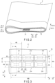
- FIG. 2 is a schematic diagram illustrating a part of the electrode group 2 housed in the battery 1 according to the embodiment.
- the height direction, lateral direction and depth direction of the battery 1 are defined.
- a first direction (indicated by arrow Z3 and arrow Z4) agrees or substantially agrees with the height direction of the battery 1.
- a second direction (indicated by arrow Y3 and arrow Y4) crosses (perpendicular or substantially perpendicular to) the first direction.
- a third direction (indicated by arrow X3 and arrow X4) crosses (perpendicular or substantially perpendicular to) both the first direction and the second direction.
- the second direction agrees or substantially agrees with the lateral direction of the battery 1.
- the third direction agrees or substantially agrees with the depth direction of the battery 1.
- the third direction is the depth direction of the joint part 31.
- the joint part 31 is formed, for example, in a connection part between the conductive member (not illustrated in FIG. 2 ) and the current collecting tab 15. Thereby, the current collecting tab 15 is joined to the conductive member, and the current collecting tab 15 and the conductive member are electrically connected.
- the joint part 31 is formed by, for example, a horn (ultrasonic horn) that is used for ultrasonic welding.
- the electrode group 2 of the present embodiment is the electrode group of the winding type.
- the ultrasonic horn is disposed at an appropriate position of the current collecting tab 15, from the outside in the lateral direction of the battery 1. The ultrasonic horn presses the current collecting tab 15 onto the conductive member, and deforms the current collecting tab 15.
- the ultrasonic horn recesses the current collecting tab 15 toward the conductive member side in the depth direction of the battery 1, and forms the joint part 31 by applying ultrasonic vibration. It is preferable that the joint part 31 is formed from the current collecting tab 15 to the conductive member along the depth direction of the battery 1 (the depth direction of the joint part 31). Thereby, since the joint part 31 is formed over both the current collecting tab 15 and the conductive member in the depth direction, the strength of joining of the current collecting tab 15 and the conductive member is increased, and thus the occurrence of a fault of the battery 1 due to defective joining of the current collecting tab 15 and the conductive member can be reduced.
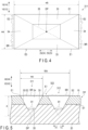
- FIG. 3 is a schematic diagram illustrating, in enlarged scale, the joint part 31 formed in the current collecting tab 15.
- the joint part 31 of the present embodiment includes a plurality of recesses, and a spacing portion 32 formed between the recesses.
- the joint part 31 of the present embodiment includes six recesses 311 to 316.
- the six recesses 311 to 316 are formed close to each other. Specifically, in the joint part 31, a plurality of recesses arranged along the first direction of the joint part 31 are formed, and a plurality of recesses arranged along the second direction of the joint part 31 are formed.
- the joint part 31 includes a plurality of recesses arranged in at least one of the first direction and second direction of the joint part 31.
- the recesses 311 to 316 are also referred to as a first recess to a sixth recess.
- the first recess 311 and second recess 312, the third recess 313 and fourth recess 314, and the fifth recess 315 and sixth recess 316 are arranged along the second direction of the joint part 31 and are formed to neighbor each other, respectively.
- the first recess 311, third recess 313, and recess 315 are arranged along the first direction of the joint part 31, and the first recess 311 and third recess 313, and the third recess 313 and fifth recess 315, are formed to neighbor each other, respectively.
- the second recess 312, fourth recess 314, and sixth recess 316 are arranged along the first direction of the joint part 31, and the second recess 312 and fourth recess 314, and the fourth recess 314 and sixth recess 316, are formed to neighbor each other, respectively.
- three recesses are formed to be arranged in the first direction of the joint part 31, and two recesses are formed to be arranged in the second direction of the joint part 31, and thus six recesses are formed close to each other.
- the spacing portion 32 includes a first spacing portion 321 and a second spacing portion 322.
- the first spacing portion 321 is formed between two recesses neighboring in the first direction of the joint part 31. Specifically, the first spacing portion 321 is formed between the first recess 311 and third recess 313, between the third recess 313 and fifth recess 315, between the second recess 312 and fourth recess 314, and between the fourth recess 314 and sixth recess 316.
- the second spacing portion 322 is formed between two recesses neighboring in the second direction of the joint part 31. Specifically, the second spacing portion 322 is formed between the first recess 311 and second recess 312, between the third recess 313 and fourth recess 314, and between the fifth recess 315 and sixth recess 316.
- the first spacing portion 321 between the first recess 311 and third recess 313, and the first spacing portion 321 between the second recess 312 and fourth recess 314, are not displaced, or not substantially displaced, in the first direction of the joint part 31.
- the first spacing portion 321 between the third recess 313 and fifth recess 315, and the first spacing portion 321 between the fourth recess 314 and sixth recess 316, are not displaced, or not substantially displaced, in the first direction of the joint part 31.
- the second spacing portion 322 between the first recess 311 and second recess 312, the second spacing portion 322 between the third recess 313 and fourth recess 314, and the second spacing portion 322 between the fifth recess 315 and sixth recess 316 are not displaced, or not substantially displaced, in the first direction of the joint part 31. Accordingly, in the joint part 31, linear or substantially linear spacing portions extending in the second direction of the joint part 31 are formed by the first spacing portions 321, and a linear or substantially linear spacing portion extending in the first direction of the joint part 31 is formed by the second spacing portions 322.
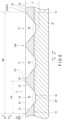
- FIG. 4 is a schematic diagram illustrating one of the recesses 311 to 316 formed in the current collecting tab 15.
- FIG. 5 is a cross-sectional view along line V-V of the joint part 31 illustrated in FIG. 3 .
- FIG. 6 is a cross-sectional view along line VI-VI of the joint part 31 illustrated in FIG. 3 .
- the recesses 311 to 316 are similarly formed.
- the same description of the structure of the recess 311 is applicable to the recesses 312 to 316.
- the first direction, second direction and third direction are defined.
- the recess 311 includes two pairs of edge portions E1 and E2, two pairs of inclined surfaces 33 and 34, and a bottom portion 35.
- the two pairs of edge portions E1 and E2 include a pair of edge portions E1, and a pair of edge portions E2.
- the paired edge portions E1 are located, spaced apart from each other in the second direction of the joint part 31.
- One of the paired edge portions E1 forms one edge of the recess 311 in regard to the second direction of the joint part 31, and the other of the paired edge portions E1 forms the other edge of the recess 311 in regard to the second direction of the joint part 31.
- the paired edge portions E1 extend in the first direction of the joint part 31 between the paired edge portions E2.
- the paired edge portions E2 are located, spaced apart from each other in the first direction of the joint part 31.
- One of the paired edge portions E2 forms one edge of the recess 311 in regard to the first direction of the joint part 31, and the other of the paired edge portions E2 forms the other edge of the recess 311 in regard to the first direction of the joint part 31.
- the paired edge portions E2 extend in the second direction of the joint part 31 between the paired edge portions E1.
- a peripheral edge portion E of the recess 311 is formed by the two pairs of edge portions E1 and E2.
- the two pairs of inclined surfaces 33 and 34 are disposed to neighbor each other.
- Each of the paired inclined surfaces 33 is formed from the edge portion E1, which forms an end of the inclined surface 33, to the bottom portion 35 in regard to the second direction of the joint part 31.
- Each of side edges of the paired inclined surfaces 33 extends toward the bottom portion 35 side relative to the end portion E1 in the second direction, as it extends toward the center side of the joint portion 31 in regard to the first direction.
- the paired inclined surfaces 33 are formed in such a state as to extend toward one side in the third direction of the joint part 31, i.e., toward the side on which the conductive member 20 is located in the third direction of the joint part 31 (the depth direction of the battery 1), as the paired inclined surfaces 33 extend toward the bottom portion 35.
- Each of the paired inclined surfaces 34 is formed from the edge portion E2, which forms an end of the inclined surface 34, to the bottom portion 35 in regard to the first direction of the joint part 31.
- Each of side edges of the paired inclined surfaces 34 extends toward the bottom portion 35 side relative to the end portion E2 in the second direction, as it extends toward the center side of the joint portion 31 in regard to the second direction.
- the paired inclined surfaces 34 are formed in such a state as to extend toward one side in the third direction of the joint part 31, i.e., toward the side on which the conductive member 20 is located in the third direction of the joint part 31 (the depth direction of the battery 1), as the paired inclined surfaces 34 extend toward the bottom portion 35.
- the two pairs of inclined surfaces 33 and 34 surround the bottom portion 35 from the outer peripheral side.
- extension planes of the two pairs of inclined surfaces 33 and 34 intersect at an intersection DP.
- the paired inclined surfaces 33 have identical or substantially identical shapes
- the paired inclined surfaces 34 have identical or substantially identical shapes.
- each of the paired inclined surfaces 33 and the paired inclined surfaces 34 has a triangular shape or a substantially triangular shape.
- a plurality of intersections DP may be formed in the recess 311.
- the extension planes of the paired inclined surfaces 33 and the extension planes of the paired inclined surfaces 34 may intersect at a plurality of points.
- a dimension between both ends of the recess 311 in the second direction of the joint part 31 is defined as wa
- a dimension between both ends of the recess 311 in the first direction of the joint part 31 is defined as wb.
- the dimension wa is less than the dimension wb. That is, wa ⁇ wb.
- the recess 311 is formed in a rectangular or a substantially rectangular shape that is elongated in the first direction of the joint part 31, as viewed from one side in the third direction of the joint portion 31.
- the dimension wa is equal to or substantially equal to the length of each of the paired edge portions E2, and the dimension wb is equal to or substantially equal to the length of each of the paired edge portions E1. Besides, it is preferable that the dimension wa is 0.2 times to 0.8 times relative to the dimension wb.
- the shape of the recess 311 is not limited to the shape illustrated in FIG. 3 and FIG. 4 . It suffices that the shape of the recess 311 satisfies the condition that the dimension wa is less than the dimension wb.
- the shape of the recess 311 may be an elliptic shape, a triangular shape, or a trapezoidal shape. In these cases, the shape of the recess 311 may be a truncated conical shape, a truncated trigonal pyramidal shape, or a truncated quadrangular pyramidal shape.
- the dimension wa is less than the dimension wb.
- the dimension wa is identical or substantially identical in the recesses 311 to 316
- the dimension wb is identical or substantially identical in the recesses 311 to 316.
- a plurality of recesses are arranged in the second direction of the joint part 31, and a plurality of recesses are arranged in the first direction of the joint part 31.
- a dimension between both ends of the joint part 31 in the second direction of the joint part 31 is defined as WA
- a dimension between both ends of the joint part 31 in the first direction of the joint part 31 is defined as WB.
- the dimension WA is less than the dimension WB. That is, WA ⁇ WB.
- the dimension WA is 0.5 mm to 5.0 mm.
- the recesses 311 to 316 are arranged two by two in the second direction of the joint part 31.
- the dimension WA in the second direction of the joint part 31 is greater than double the dimension wa in the second direction of each of the recesses 311 to 316. That is, WA > 2 ⁇ wa.
- the recesses 311 to 316 are arranged three by three in the first direction of the joint part 31.
- the dimension WB in the first direction of the joint part 31 is greater than three times the dimension wb in the first direction of each of the recesses 311 to 316. That is, WB > 3 ⁇ wb.
- the dimension of the first spacing portion 321 in the first direction is half the difference between the dimension WB and three times the dimension wb, i.e., (WB - 3 ⁇ wb)/2.
- the dimension of the second spacing portion 322 in the second direction is the difference between the dimension WA and double the dimension wa, i.e., WA - 2 ⁇ wa.
- the dimension of the first spacing portion 321 in the first direction may not be equal between the plural first spacing portions 321.
- the total of the dimensions in the first direction of the joint part 31 is WB - 3 ⁇ wb.
- the total of the dimensions in the.first direction of both the first spacing portion 321 between the recess 311 and recess 313, and the first spacing portion 321 between the recess 313 and recess 315 is WB - 3 ⁇ wb.
- the total of the dimensions in the first direction of both the first spacing portion 321 between the recess 312 and recess 314, and the first spacing portion 321 between the recess 314 and recess 316 is WB - 3 ⁇ wb.
- the joint part 31 includes m ⁇ n recesses.
- the joint part 31 satisfies WA ⁇ WB.
- the dimension WA of the joint part 31 is greater than m times the dimension wa of the recess
- the dimension WB of the joint part 31 is greater than n times the dimension wb of the recess. That is, WA > m ⁇ wa, and WB > n ⁇ wb.
- the dimension of the first spacing portion 321 in the first direction is 1/(n - 1) of the difference between the dimension WB of the joint part 31 and n times the dimension wb of the recess, i.e., (WB - n ⁇ wb)/(n - 1).
- the dimension of the second spacing portion 322 in the second direction is 1/(m - 1) of the difference between the dimension WA of the joint part 31 and m times the dimension wa of the recess, i.e., (WA - m ⁇ wa)/(m - 1).
- the dimension of each of the first spacing portions 321 is not particularly limited.
- the dimension of each of the second spacing portions 322 is not particularly limited.
- the dimension between both ends in the second direction is less that the dimension between both ends in the first direction.
- the dimensions between both ends in the second direction of the respective recesses are wa1, wa2,..., wan, and the dimensions between both ends in the first direction of the respective recesses are wb1, wb2,..., wbm, WA > wa1 + wa2 + ... + wan, and WB > wb1 + wb2 + ... + wbm.
- the current collecting tab 15 includes surfaces S1 and S2.
- the surface S1 faces a side on which the conductive member 20 is located in the third direction of the joint part 31.
- the surface S2 faces an opposite side (an opposite side to the conductive member 20 side) to the surface S1 in the third direction of the joint part 31.
- the surface S1 of the current collecting tab 15 is in contact with the conductive member 20.
- the paired inclined surfaces 33 are inclined to the surface S1 and inclined to the surface S2. The paired inclined surfaces 33 are formed beyond the surface S1 of the current collecting tab 15 in the third direction of the joint portion 31.
- the paired surfaces 33 are formed from the current collecting tab 15 into the conductive member 20. In other words, the paired surfaces 33 are formed from the surface S2 of the current collecting tab 15 into the inside of the conductive member 20.
- the paired inclined surfaces 34 are inclined to the surface S1 and inclined to the surface S2. The paired inclined surfaces 34 are formed beyond the surface S1 of the current collecting tab 15 in the third direction of the joint portion 31.
- the paired inclined surfaces 34 are formed from the current collecting tab 15 into the conductive member 20. In other words, the paired inclined surfaces 34 are formed from the surface S2 of the current collecting tab 15 into the inside of the conductive member 20.
- the intersection DP is located in the inside of the conductive member 20 in the third direction of the joint part 31. In other words, the intersection DP is formed further toward the side on which the conductive member 20 is located, relative to the surface S1 in the third direction of the joint part 31.
- a recess distance d of the recess 311 in the third direction is an imaginary distance from the surface S2 of the current collecting tab 15 to the intersection DP.
- the recess distance d of the recess 311 is greater than the thickness of the current collecting tab 15 (i.e., the dimension in the third direction of the joint part 31 from the surface S1 to the surface S2).
- the intersection DP is not located beyond the conductive member 20 in the third direction.
- the recess distance d of the recess 311 is less than the total thickness of the thickness of the current collecting tab 15 and the thickness of the conductive member 20.
- the recess distance d of the recess 311 is greater than half the dimension wa of the recess 311. In regard to the recess distance d, it is preferable that d > wa/2.
- the intersection DP is located at the center position of the recess 311 in the second direction of the joint part 31.
- the recess 311 is formed symmetric with respect to a plane that passes through the intersection DP and is perpendicular or substantially perpendicular to the second direction. It is thus preferable that, as illustrated in FIG. 5 , an angle ⁇ 1 between the paired inclined surfaces 33 is an acute angle.
- the angle ⁇ 1 between the paired inclined surfaces 33 is less than 45°. In addition, it is preferable that the angle ⁇ 1 between the paired inclined surfaces 33 is greater than 30°. Specifically, it is more preferable that the angle ⁇ 1 between the paired inclined surfaces 33 is greater than 30° and is less than 45°.
- the recess distance d in the recess 311 is the distance from the surface S2 of the current collecting tab 15 to the intersection DP. Since the paired inclined surfaces 34 are formed to have the identical or substantially identical shapes, as described above, the intersection DP is located at the center position of the recess 311 in the first direction of the joint part 31. Thus, the recess 311 is formed symmetric with respect to a plane that passes through the intersection DP and is perpendicular or substantially perpendicular to the first direction. At this time, an angle ⁇ 2 between the paired inclined surfaces 34 is not particularly limited.
- the angle ⁇ 2 between the paired inclined surfaces 34 is determined on the condition that wb is greater than wa and the angle ⁇ 1 between the paired inclined surfaces 33 is an acute angle. Accordingly, it is preferable that the angle ⁇ 2 between the paired inclined surfaces 34 is greater than the angle ⁇ 1 between the paired inclined surfaces 33. It is more preferable that the angle ⁇ 2 between the paired inclined surfaces 34 is an obtuse angle.
- the recess distance d is defined for each of the recesses. Specifically, in each of the recesses, it is preferable that the recess distance d is greater than half the dimension between both ends of the recess in the second direction.
- burrs BR are formed on the peripheral edge portion E of the recess 311.
- the burrs BR are formed when the current collecting tab 15 is recessed by the ultrasonic horn.
- the ultrasonic horn is pressed on the current collecting tab 15, while vibrating in the first direction of the joint part 31, thereby forming the recess 311.
- the current collecting tab 15 is pushed by the ultrasonic horn toward the side on which the conductive member 20 is located, and vibration along the first direction of the joint part 31 is applied to the current collecting tab 15.
- the ultrasonic horn that vibrates in the extending direction of the paired edge portions E1 forms the paired edge portions E1 in the current collecting tab 15.
- the ultrasonic horn that vibrates in a direction crossing (perpendicular or substantially perpendicular to) the paired edge portions E2 formed in the current collecting tab 15 forms the paired edge portions E2 in the current collecting tab 15.
- the residual amount of burrs BR is different between the paired edge portions E1 and the paired edge portions E2.
- the residual amount of burrs is greater in the part neighboring the recess 311 from the first direction, than in the part neighboring the recess 311 from the second direction.
- the part neighboring the recess 311 from the first direction is, for example, the part neighboring the paired edge portions E2 from the first direction.
- the part neighboring the recess 311 from the second direction is, for example, the part neighboring the paired edge portions E1 from the second direction.
- FIG. 4 and FIG. 5 do not illustrate burrs BR formed on the paired edge portions E1.
- the burrs BR may not be formed over the entire dimensions of the paired edge portions E2.
- the burrs BR may be formed only on parts of the paired edge portions E2.
- the burrs BR are formed on the peripheral edge portion E, and the residual amount of the formed burrs BR is greater on the paired edge portions E2 than on the paired edge portions E1. Accordingly, in the joint part 31 of the present embodiment, the dimension of the edge portion, where the residual amount of burrs BR is large, is less than the dimension of the edge portion, where the residual amount of burrs BR is small.
- the burrs BR are formed on the peripheral edge portions E of the recesses 311 to 316.
- the recesses 311 to 316 are formed by the ultrasonic horn that vibrates in the vibrating direction along the first direction of the joint part 31.
- the residual amount of burrs BR formed on edge portions E2 (referred to as "outermost edge portions EO") located outermost in the first direction of the joint part 31 is greater than the residual amount of burrs BR formed on the other edge portions E1 and E2.
- the cause of the occurrence of the difference in the residual amount of burrs is assumed to be that the burrs formed on the edge portions other than the outermost edge portions EO are removed by the pressing on the current collecting tab 15 and vibration.
- the edge portion E2 located outside in the first direction of the joint part 31 is the outermost edge portion EO.
- the edge portion E2 located outside in the first direction of the joint part 31 is the outermost edge portion EO.
- the edge portion E2 located outside in the first direction of the joint part 31 is the outermost edge portion EO.
- the edge portion E2 located outside in the first direction of the joint part 31 is the outermost edge portion EO.
- the joint part 31 connects the current collecting tab 15 and the conductive member 20.
- the joint part 31 includes the recess and the peripheral edge portion E.
- the recess is recessed in the current collecting tab 15 toward the side on which the conductive member 20 is located, and a second dimension wa between both ends in the second direction is less than a first dimension wb between both ends in the first direction.
- the peripheral edge portion E surrounds the recess, and the residual amount of burrs is greater in the part neighboring the recess from the first direction than the part neighboring the recess from the second direction.
- the dimension of the part, where the residual amount of burrs BR is greater than in the other part can be formed to be smaller.
- the total amount of burrs, which occur when the joint part 31 is formed can be reduced.
- the joint part 31 is formed to extend from the current collecting tab 15 to the conductive member 20.
- the joint part 31 is formed on both sides, with the surface S1 being interposed. Thereby, the current collecting tab 15 and the conductive member 20 can fully be joined.
- the joint part 31 includes a plurality of recesses, and includes a peripheral edge portion for each of the recesses.
- a fourth dimension WA between both ends in the second direction is less than a third dimension WB between both ends in the first direction.
- the residual amount of burrs is greater in the outermost part of the joint part 31 in the first direction than in the other parts.
- the second dimension wa is 0.2 times to 0.8 times of the first dimension wb.
- the dimension of the recess 311 in the direction crossing (perpendicular or substantially perpendicular to) the vibrating direction can be reduced in the joining by the ultrasonic horn that vibrates in the first direction of the joint part 31.
- the second dimension wa is equal to or greater than 0.2 times the first dimension wb, the second dimension wa is not too small, and thus the possibility of breakage of the current collecting tab 15 that is the joining target decreases.
- the second dimension wa is equal to or less than 0.8 times the first dimension wb, since a difference in dimensions between the first direction and the second direction can sufficiently be secured, the advantageous effects in the present embodiment can fully be obtained.
- the recess distance d of the recess is greater than half the second dimension wa.
- a joint part 31 including the recesses of the embodiment was formed by joining the current collecting tab 15 and the conductive member 20 by ultrasonic welding by the ultrasonic horn.
- a comparative example by forming a joint part 31 including recesses each of in which edge portions E1 and E2 have identical dimensions, the current collecting tab 15 and the conductive member 20 are joined by ultrasonic welding by the ultrasonic horn.
- the number of recesses is one row in the second direction of the joint part 31, and three rows in the first direction of the joint part 31. Accordingly, in each of the example and the comparative example, three recesses in total are formed at a time.
- the vibrating direction of the ultrasonic horn is made to substantially agree with the first direction of the joint part 31.
- a test was conducted five times.
- the values of ⁇ 1, ⁇ 2, wa, and wb in each recess are set as indicated in the table below. (Table 1) ⁇ 1 (°) ⁇ 2 (°) wa (mm) wb (mm)
- Example 60 90 3.1 4.7 Comparative example 90 90 4.7 4.7
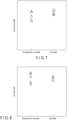
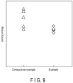
- the results are illustrated in FIG. 7 to FIG. 9 .
- the ordinate axis of FIG. 7 indicates joining strength
- the ordinate axis of FIG. 8 indicates joining time
- the ordinate axis of FIG. 9 indicates joining energy.
- the units in the ordinate axes of FIG. 7 to FIG. 9 are discretionary units corresponding to the respective items.
- the joining strength of the recesses of the example has less nonuniformity than the joining strength of the recesses of the comparative example.
- the joining time of the recesses of the example has less nonuniformity than the joining time of the recesses of the comparative example.
- the joining energy of the recesses of the example has less nonuniformity than the joining energy of the recesses of the comparative example. It is considered that these results are due to the fact that the stability of joining at a time of performing one-time joining is improved (the reproducibility of joining is improved) by the reduction in the occurrence of burrs in the recesses of the example. Thus, by reducing the occurrence of burrs, the improvement of the joining property of members by recesses is exhibited.
- the bottom portion 35 may be formed at the same position as the intersection DP in the third direction. In this case, the bottom portion 35 agrees or substantially agrees with the intersection DP.
- the two pairs of inclined surfaces 33 and 34 have the same structure as in the above-described embodiment.
- the intersection DP is located at the bottom portion 35, and the shape of the recess is, for example, a trigonal pyramidal shape, or a quadrangular pyramidal shape, or a conical shape.
- the recess distance d coincides with the depth of the recess.
- the peripheral edge portion E surrounds the recess, and the residual amount of burrs is greater in the part neighboring the recess from the first direction, than in the part neighboring the recess from the second direction.
- FIG. 10 is a cross-sectional view schematically illustrating a modification of the battery 1 according to the embodiment, by a cross section perpendicular to the depth direction of the battery 1.
- the height direction, lateral direction and depth direction of the battery 1 are defined.
- the first direction (indicated by arrow Y5 and Y6) agrees or substantially agrees with the lateral direction of the battery 1.
- the second direction (indicated by arrow Z5 and arrow Z6) agrees or substantially agrees with the height direction of the battery 1.
- the third direction agrees or substantially agrees with the depth direction of the battery 1.
- a pair of current collecting tabs 15 protrude to the same side.
- the paired current collecting tabs 15 protrude from the electrode group 2 to the side on which the paired electrode terminals 16 are located in the height direction of the battery 1.
- the paired current collecting tabs 15 are not in contact with each other.
- the positive electrode current collecting tab 15A protrudes from the electrode group 2 to the side on which the positive electrode terminal 16A is located.
- the negative electrode current collecting tab 15B protrudes from the electrode group 2 to the side on which the negative electrode terminal 16B is located. In this case, too, as illustrated in FIG.
- the peripheral edge portion E surrounds the recess, and the residual amount of burrs is greater in the part neighboring the recess from the first direction, than in the part neighboring the recess from the second direction.
- the container member of the battery 1 is not limited to the configuration in which the container member is composed of the outer container 5 and the lid 6.
- the container unit may be composed of a first container member and a second container member, which are formed of a metal.
- the first container member includes a bottom wall and a peripheral wall, and, in the first container member, a flange in the peripheral wall protrudes to the outer peripheral side from an end portion opposite to the bottom wall.
- the second container member is attached to the flange of the first container member.
- the container unit of the battery may be formed of a laminate film of a three-layer structure in which a metal layer is sandwiched between resin layers.
- the joint part 31 is formed in the current collecting tab 15.
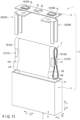
- FIG. 11 is a perspective view schematically illustrating an example of a battery according to a modification of the embodiment.
- the height direction, lateral direction and depth direction of the battery 1 are defined, and the first direction, second direction and third direction of the joint part 31 are defined.
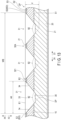
- FIG. 12 is a cross-sectional view illustrating the joint part 31 illustrated in FIG. 11 , by a cross section perpendicular or substantially perpendicular to the first direction.
- FIG. 13 is a cross-sectional view illustrating the joint part 31 illustrated in FIG. 11 , by a cross section perpendicular or substantially to the second direction.
- the height direction, lateral direction and depth direction of the battery 1 are defined, and the first direction, second direction and third direction of the joint part 31 are defined.
- the conductive member 20 is composed of a plurality of members.
- a backup lead 21 functioning as a member of the conductive member 20 is attached to the current collecting tab 15.
- a positive electrode-side backup lead 21A is attached to the positive electrode current collecting tab 15A
- a negative electrode-side backup lead 21B is attached to the negative electrode current collecting tab 15B.
- the backup lead 21 includes a surface S3.
- the surface S3 faces an opposite side (a side opposite to the current collecting tab 15 side) to the surface S1 in the third direction of the joint part 31, and forms a front surface of the joint part 31.
- the paired inclined surfaces 33 are formed from the surface S3 of the backup lead 21 into the inside of the conductive member 20, and the paired inclined surfaces 34 are formed from the surface S3 of the backup lead 21 into the inside of the conductive member 20.
- the recess distance d is a distance from the surface S3 of the backup lead 21 to the intersection DP.
- the intersection DP may be located further toward the conductive member 20 side relative to the surface S1 of the current collecting tab 15 in the third direction.
- the intersection DP may be located in the backup lead 21 on the side of contact with the conductive member 20 in the third direction.
- the two pairs of inclined surfaces 33 and 34 are formed from the backup lead 21 on the side of contact with the current collecting tab 15 to the vicinity of the backup lead 21 on the side of contact with the conductive member 20 in the third direction.
- the peripheral edge portion E surrounds the recess, and the residual amount of burrs is greater in the part neighboring the recess from the first direction, than in the part neighboring the recess from the second direction.
- the joint part that connects the current collecting tab of the battery and the conductive member includes the recess and the peripheral edge portion.
- the recess is recessed toward the side on which the conductive member is located in the current collecting tab, and the second dimension between both ends in the second direction is less than the first dimension between both ends in the first direction in the recess.
- the peripheral edge portion surrounds the recess, and the residual amount of burrs is greater in the part neighboring the recess from the first direction, than in the part neighboring the recess from the second direction.
Landscapes
- Chemical & Material Sciences (AREA)
- Chemical Kinetics & Catalysis (AREA)
- Electrochemistry (AREA)
- General Chemical & Material Sciences (AREA)
- Engineering & Computer Science (AREA)
- Mechanical Engineering (AREA)
- Manufacturing & Machinery (AREA)
- Connection Of Batteries Or Terminals (AREA)
Abstract
Description
- Embodiments of the present invention relate generally to a battery and a manufacturing method of a battery.
- As a battery such as a lithium ion secondary battery, there is known such a battery that an electrode group including a positive electrode and a negative electrode is housed in an inner cavity of a container member. In this battery, an electrode terminal is disposed in the container member. Furthermore, the electrode group includes a current collector and an active material-containing layer supported on the current collector. The current collector includes a current collecting tab as a part on which the active material-containing layer is not supported. The current collecting tab is electrically connected to the electrode terminal via a conductive material such as a lead. In addition, a plurality of belt-shaped portions are stacked in the current collecting tab.
- In manufacturing such a battery, the belt-shaped portions stacked in the current collecting tab are joined to a conductive member or the like by ultrasonic welding. Specifically, the stacked belt-shaped portions of the current collecting tab and the conductive member are mutually joined by being deformed. If the belt-shaped portions and the conductive member are joined in this manner, a recess is formed in a connection part, and there may be a case where burrs are formed on a peripheral edge or the like of the recess. The burrs are protrusions occurring on the above-described peripheral edge or the like during the process of forming the recess, or a residual portion of the belt-shaped portion or the like. In the joining, it is required to reduce the formation of burrs on the peripheral edge or the like of the recess that joins the belt-shaped portion and the conductive member.
-
- Patent document 1: Jpn. Pat. Appln. KOKAI Publication No.
2017-074611 - Patent document 2: Jpn. Pat. Appln. KOKAI Publication No.
2018-094559 - Patent document 3: Jpn. Pat. Appln. KOKAI Publication No.
2007-330851 - Patent document 4: Jpn. Pat. Appln. KOKAI Publication No.
2017-054704 - The problem to be solved by the present invention is to provide a battery and a manufacturing method of a battery, which can reduce the formation of burrs on a peripheral edge or the like of a recess that joins a belt-shaped portion and a conductive member.
- According to an embodiment, a battery includes a container member, an electrode terminal, an electrode group, a conductive member and a joint part. The electrode terminal is disposed in the container member. The electrode group is housed in an inner cavity of the container member, and includes a current collecting tab that protrudes. The conductive member electrically connects the electrode terminal and the current collecting tab. The joint part connects the current collecting tab and the conductive member. The joint part includes a recess and a peripheral edge portion. The recess is recessed toward a side on which the conductive member is located in the current collecting tab, and a second dimension between both ends in a second direction of the recess is less than a first dimension between both ends in a first direction of the recess, the second direction crossing the first direction. The peripheral edge portion surrounds the recess, and a residual amount of burrs is greater in a part neighboring the recess from the first direction, than in a part neighboring the recess from the second direction.
-
-
FIG. 1 is a perspective view schematically illustrating an example of a battery according to an embodiment. -
FIG. 2 is a perspective view schematically illustrating a configuration of an electrode group ofFIG. 1 . -
FIG. 3 is a schematic diagram illustrating a configuration of a current collecting tab of the electrode group ofFIG. 1 . -
FIG. 4 is a schematic diagram illustrating an example of a recess of the current collecting tab formed in the electrode group ofFIG. 1 . -
FIG. 5 is a cross-sectional view schematically illustrating a V-V cross section inFIG. 3 . -
FIG. 6 is a cross-sectional view schematically illustrating a VI-VI cross section inFIG. 3 . -
FIG. 7 is a diagram illustrating a joining strength at a time when a recess according to the embodiment is formed. -
FIG. 8 is a diagram illustrating a joining time at a time when the recess according to the embodiment is formed. -
FIG. 9 is a diagram illustrating a joining energy at a time when the recess according to the embodiment is formed. -
FIG. 10 is a cross-sectional view schematically illustrating a battery according to a modification of the embodiment, by a cross section perpendicular to a depth direction of the battery. -
FIG. 11 is a perspective view schematically illustrating an example of a battery according to another modification of the embodiment. -
FIG. 12 is a cross-sectional view schematically illustrating a joint part of the battery according to the another modification illustrated inFIG. 11 , by a cross section perpendicular to a first direction. -
FIG. 12 is a cross-sectional view schematically illustrating the joint part of the battery according to the another modification illustrated inFIG. 11 , by a cross section perpendicular to a second direction. - Hereinafter, an embodiment will be described with reference to the drawings.
-
FIG. 1 illustrates abattery 1 according to an embodiment. As illustrated inFIG. 1 , thebattery 1 includes anelectrode group 2 and acontainer member 3. Thecontainer member 3 includes anouter container 5 and alid 6. Each of theouter container 5 and thelid 6 is made of a metal such as aluminum, an aluminum alloy, iron, copper, or stainless steel. Here, in the battery 1 (outer container 5), a depth direction (indicated by arrow X1 and arrow X2), a lateral direction (indicated by arrow Y1 and arrow Y2) crossing (perpendicular or substantially perpendicular to) the depth direction, and a height direction (indicated by arrow Z1 and arrow Z2) crossing (perpendicular or substantially perpendicular to) both the depth direction and the lateral direction, are defined. In each of thebattery 1 and theouter container 5, a dimension in the depth direction is less than a dimension in the lateral direction and a dimension in the height direction. Note thatFIG. 1 is a perspective view illustrating the individual members being exploded. - The
outer container 5 includes abottom wall 7 and aperipheral wall 8. Thebottom wall 7 and theperipheral wall 8 define aninner cavity 10 configured to house theelectrode group 2. In theouter container 5, theinner cavity 10 opens to a side opposite to a side on which thebottom wall 7 is located in the height direction. Thelid 6 is attached to theperipheral wall 8 at an end opposite to thebottom wall 7. Accordingly, thelid 6 closes the opening of theinner cavity 10 of theouter container 5. Thelid 6 and thebottom wall 7 are opposed to each other, with theinner cavity 10 being interposed in the height direction. - The
electrode group 2 includes a pair ofelectrodes 13, a pair ofcurrent collectors 14, and a pair ofcurrent collecting tabs 15. One of the pairedelectrodes 13 is apositive electrode 13A, and the other of the pairedelectrodes 13, which is different from thepositive electrode 13A, is anegative electrode 13B. One of the pairedcurrent collectors 14 is a positive electrodecurrent collector 14A, and the other of the pairedcurrent collectors 14, which is different from the positive electrodecurrent collector 14A, is a negative electrodecurrent collector 14B. One of the pairedcurrent collecting tabs 15 is a positive electrodecurrent collecting tab 15A, and the other of the pairedcurrent collecting tabs 15, which is different from the positive electrodecurrent collecting tab 15A, is a negative electrodecurrent collecting tab 15B. In each of the pairedcurrent collecting tab 15, a plurality of belt-shaped portions is bundled. In theelectrode group 2, a separator (not illustrated) is interposed between thepositive electrode 13A and thenegative electrode 13B. The separator is formed of a material having an electrical insulation property, and electrically insulates thepositive electrode 13A from thenegative electrode 13B. - The positive electrode
current collector 14A is formed of a positive electrode current collecting foil or the like. A positive electrode active material-containing layer (not illustrated) is formed on a surface of the positive electrodecurrent collector 14A. The positive electrodecurrent collector 14A is, for example, an aluminum foil or an aluminum alloy foil. The positive electrodecurrent collector 14A has a thickness of about 10 um to 20 um. The positive electrode active material-containing layer includes a positive electrode active material. The positive electrode active material-containing layer may optionally contain a binder and an electro-conductive agent. Examples of the positive electrode active material include oxides, sulfides, and polymers capable of occluding and releasing lithium ions. The positive electrodecurrent collecting tab 15A is a portion (unsupported portion) of the positive electrodecurrent collector 14A, on which the positive electrode active material-containing layer is not supported. The positive electrodecurrent collecting tab 15A protrudes relative to thenegative electrode 13B and the separator. - The negative electrode
current collector 14B is formed of a negative electrode current collecting foil or the like. A negative electrode active material-containing layer (not illustrated) is formed on a surface of the negative electrodecurrent collector 14B. The negative electrodecurrent collector 14B is, for example, an aluminum foil, an aluminum alloy foil, or a copper foil. The negative electrodecurrent collector 14B has a thickness of about 10 µm to 20 µm. The negative electrode active material-containing layer includes a negative electrode active material. The negative electrode active material-containing layer may optionally contain a binder and an electro-conductive agent. Examples of the negative electrode active material include metal oxides, metal sulfides, metal nitrides, and carbon materials capable of occluding and releasing lithium ions. The negative electrodecurrent collecting tab 15B is a portion (unsupported portion) of the negative electrodecurrent collector 14B, on which the negative electrode active material-containing layer is not supported. The negative electrodecurrent collecting tab 15B protrudes, relative to thepositive electrode 13A and the separator, to a side opposite to a side toward which the positive electrodecurrent collecting tab 15A protrudes. - In one example of the
electrode group 2, thepositive electrode 13A, thenegative electrode 13B, and the separator are wound around a winding axis W. Thepositive electrode 13A is provided by being displaced to one side in an axial direction along the winding axis W, relative to the separator. Thenegative electrode 13B is provided by being displaced to an opposite side to thepositive electrode 13A in the axial direction, relative to the separator. Thus, the paired current collecting tabs 15 (positive electrodecurrent collecting tab 15A and negative electrodecurrent collecting tab 15B) protrude outward in the axial direction, relative to the separator. In this case, the positive electrodecurrent collecting tab 15A protrudes to one side in the axial direction, relative to the separator. The negative electrodecurrent collecting tab 15B protrudes, relative to the separator, to an opposite side to the side toward which the positive electrodecurrent collecting tab 15A protrudes. - In another example of the
electrode group 2, a plurality ofpositive electrodes 13A and a plurality ofnegative electrodes 13B are alternatively stacked. In other words, theelectrode group 2 has a stack structure. Thepositive electrodes 13A are provided by being displaced to one side, relative to the separator. Thenegative electrodes 13B are provided by being displaced to an opposite side to thepositive electrodes 13A, relative to the separator. Thus, the pairedcurrent collecting tabs 15 protrude outward, relative to the separator. Specifically, the positive electrodecurrent collecting tab 15A protrudes in a lateral direction of thebattery 1, relative to the separator, and the negative electrodecurrent collecting tab 15B protrudes, relative to the separator, to an opposite side to the positive electrodecurrent collecting tab 15A in the lateral direction of thebattery 1. - In the description below, it is assumed that the
electrode group 2 is an electrode group of the above-described winding type, but theelectrode group 2 is not limited to this. As illustrated inFIG. 1 , one of the pairedcurrent collecting tabs 15 protrudes to one side in the lateral direction of the battery 1 (the axial direction along the winding axis W). The other of the pairedcurrent collecting tabs 15 protrudes to the opposite side to the side toward which the one of the pairedcurrent collecting tabs 15 protrudes in the lateral direction of thebattery 1. In other words, the positive electrodecurrent collecting tab 15A protrudes to one side in the lateral direction of thebattery 1, and the negative electrodecurrent collecting tab 15B protrudes to the other side in the lateral direction of thebattery 1. - In the
inner cavity 10, an electrolytic solution (not illustrated) is held (impregnated) in theelectrode group 2. The electrolytic solution may be a nonaqueous electrolytic solution having an electrolyte dissolved in an organic solvent or may be an aqueous electrolytic solution such as an aqueous solution. A gel electrolyte or a solid electrolyte may be used in place of the electrolytic solution. In a case where a solid electrolyte is employed as the electrolyte, the solid electrolyte, instead of the separator, is interposed between thepositive electrode 13A and thenegative electrode 13B in the electrode group. In this case, thepositive electrode 13A is electrically insulated from thenegative electrode 13B by the solid electrolyte. - In the
battery 1, a pair ofelectrode terminals 16 is attached to the outer surface of thelid 6. The pairedelectrode terminals 16 are exposed to the outside of thebattery 1, and are disposed on the outer surface of thelid 6. Accordingly, the pairedelectrode terminals 16 are disposed in thecontainer member 3. The pairedelectrode terminals 16 are made of a conductive material such as a metal. One of the pairedelectrode terminals 16 is apositive electrode terminal 16A of thebattery 1. The other of the pairedelectrode terminals 16, which is different from thepositive electrode terminal 16A, is anegative electrode terminal 16B of thebattery 1. On the outer surface of thelid 6, an insulatingmember 18 is provided between each of the pairedelectrode terminals 16 and thelid 6. Each of the pairedelectrode terminals 16 is electrically insulated from theouter container 5 and thelid 6 by the insulatingmember 18. - A pair of
conductive members 20 is disposed in theinner cavity 10 of theouter container 5. One of the pairedconductive members 20 is a positive electrode conductive member 20A. The other of the pairedconductive members 20, which is different from the positive electrode conductive member 20A, is a negative electrodeconductive member 20B. The positive electrode conductive member 20A forms at least a part of an electrical path between the positive electrodecurrent collecting tab 15A and thepositive electrode terminal 16A. Thus, the positive electrodecurrent collecting tab 15A is electrically connected to thepositive electrode terminal 16A through at least the positive electrode conductive member 20A. The negative electrodeconductive member 20B forms at least a part of an electrical path between the negative electrodecurrent collecting tab 15B and thenegative electrode terminal 16B. Thus, the negative electrodecurrent collecting tab 15B is electrically connected to thenegative electrode terminal 16B through at least the negative electrodeconductive member 20B. Each of theconductive members 20 is made of a conductive material such as a metal. Examples of the conductive material, of which theconductive members 20 are formed, include aluminum, stainless steel, copper, and iron. For example, the pair ofconductive members 20 is a pair of leads. - In each of the paired
current collecting tabs 15, a plurality of belt-shaped portions are stacked. In manufacturing thebattery 1, before each of thecurrent collecting tabs 15 is electrically connected to the corresponding one of theelectrode terminals 16, the belt-shaped portions are bundled in each of the pairedcurrent collecting tabs 15. Accordingly, in each of thecurrent collecting tabs 15, the bundled belt-shaped portions are electrically connected to the corresponding one of theelectrode terminals 16 via the corresponding one of theconductive members 20. Specifically, the bundled belt-shaped portions of the positive electrodecurrent collecting tab 15A are electrically connected to thepositive electrode terminal 16A via the positive electrode conductive member 20A. The bundled belt-shaped portions of the negative electrodecurrent collecting tab 15B are electrically connected to thenegative electrode terminal 16B via the negative electrodeconductive member 20B. Note that in the example ofFIG. 1 , each of the pairedconductive members 20 includes a pair of leg portions, and is formed in a two-forked shape. In addition, in each of theconductive members 20, at least one of the paired leg portions is connected to the bundled belt-shaped portions of the corresponding one of thecurrent collecting tabs 15. In another example, each of theconductive members 20 may be configured to be provided with only one leg portion. In this case, in each of theconductive members 20, the leg portion, which is the only one leg portion, is connected to the bundled belt-shaped portions of the corresponding one of thecurrent collecting tabs 15. - In the example in
FIG. 1 , thelid 6 is provided with agas release valve 23 and a filling port (not illustrated). In addition, a sealingplate 25 that closes the filling port is welded on the outer surface of thelid 6. Note that thebattery 1 is not necessarily provided with, for example, thegas release valve 23 and the filling port. In theinner cavity 10 of theouter container 5, the current collecting tabs (15A and 15B) and the pairedconductive members 20 are electrically insulated from theouter container 5 by one or more insulating members (not illustrated). - Next, a
joint part 31, which is formed in each of the pairedcurrent collecting tabs 15 of theelectrode group 2, is described. Specifically, as illustrated inFIG. 1 , a positive electrode-sidejoint part 31A is formed in the positive electrodecurrent collecting tab 15A, and a negative electrode-sidejoint part 31B is formed in the negative electrodecurrent collecting tab 15B. Here, the positive electrode-sidejoint part 31A and the negative electrode-sidejoint part 31B are similarly constituted. Thus, the same description of the structure of the positive electrode-sidejoint part 31A is applicable to the negative electrode-sidejoint part 31B. Hereinafter, the description is given on the assumption that the positive electrodecurrent collecting tab 15A is thecurrent collecting tab 15, and the positive electrode-sidejoint part 31A is thejoint part 31, and the description of the negative electrodecurrent collecting tab 15B and negative electrode-sidejoint part 31B is omitted. Note that thejoint part 31 may not be formed in both of the pairedcurrent collecting tabs 15. In other words, thejoint part 31 may be formed in only one of the pairedcurrent collecting tabs 15, or may be formed in each of both of the pairedcurrent collecting tabs 15. -
FIG. 2 is a schematic diagram illustrating a part of theelectrode group 2 housed in thebattery 1 according to the embodiment. InFIG. 2 , likeFIG. 1 , the height direction, lateral direction and depth direction of thebattery 1 are defined. In addition, in thejoint part 31, a first direction (indicated by arrow Z3 and arrow Z4) agrees or substantially agrees with the height direction of thebattery 1. A second direction (indicated by arrow Y3 and arrow Y4) crosses (perpendicular or substantially perpendicular to) the first direction. A third direction (indicated by arrow X3 and arrow X4) crosses (perpendicular or substantially perpendicular to) both the first direction and the second direction. In the present embodiment, the second direction agrees or substantially agrees with the lateral direction of thebattery 1. The third direction agrees or substantially agrees with the depth direction of thebattery 1. In addition, the third direction is the depth direction of thejoint part 31. - The
joint part 31 is formed, for example, in a connection part between the conductive member (not illustrated inFIG. 2 ) and thecurrent collecting tab 15. Thereby, thecurrent collecting tab 15 is joined to the conductive member, and thecurrent collecting tab 15 and the conductive member are electrically connected. Thejoint part 31 is formed by, for example, a horn (ultrasonic horn) that is used for ultrasonic welding. As described above, theelectrode group 2 of the present embodiment is the electrode group of the winding type. Thus, the ultrasonic horn is disposed at an appropriate position of thecurrent collecting tab 15, from the outside in the lateral direction of thebattery 1. The ultrasonic horn presses thecurrent collecting tab 15 onto the conductive member, and deforms thecurrent collecting tab 15. The ultrasonic horn recesses thecurrent collecting tab 15 toward the conductive member side in the depth direction of thebattery 1, and forms thejoint part 31 by applying ultrasonic vibration. It is preferable that thejoint part 31 is formed from thecurrent collecting tab 15 to the conductive member along the depth direction of the battery 1 (the depth direction of the joint part 31). Thereby, since thejoint part 31 is formed over both thecurrent collecting tab 15 and the conductive member in the depth direction, the strength of joining of thecurrent collecting tab 15 and the conductive member is increased, and thus the occurrence of a fault of thebattery 1 due to defective joining of thecurrent collecting tab 15 and the conductive member can be reduced. -
FIG. 3 is a schematic diagram illustrating, in enlarged scale, thejoint part 31 formed in thecurrent collecting tab 15. InFIG. 3 , likeFIG. 2 , the first direction, second direction and third direction of thejoint part 31 are defined. As illustrated inFIG. 3 , thejoint part 31 of the present embodiment includes a plurality of recesses, and aspacing portion 32 formed between the recesses. Thejoint part 31 of the present embodiment includes sixrecesses 311 to 316. The sixrecesses 311 to 316 are formed close to each other. Specifically, in thejoint part 31, a plurality of recesses arranged along the first direction of thejoint part 31 are formed, and a plurality of recesses arranged along the second direction of thejoint part 31 are formed. Thus, thejoint part 31 includes a plurality of recesses arranged in at least one of the first direction and second direction of thejoint part 31. Hereinafter, therecesses 311 to 316 are also referred to as a first recess to a sixth recess. - In the
joint part 31 of the present embodiment, thefirst recess 311 andsecond recess 312, thethird recess 313 andfourth recess 314, and thefifth recess 315 andsixth recess 316, are arranged along the second direction of thejoint part 31 and are formed to neighbor each other, respectively. In addition, thefirst recess 311,third recess 313, andrecess 315 are arranged along the first direction of thejoint part 31, and thefirst recess 311 andthird recess 313, and thethird recess 313 andfifth recess 315, are formed to neighbor each other, respectively. Similarly, thesecond recess 312,fourth recess 314, andsixth recess 316 are arranged along the first direction of thejoint part 31, and thesecond recess 312 andfourth recess 314, and thefourth recess 314 andsixth recess 316, are formed to neighbor each other, respectively. In this manner, in thejoint part 31, three recesses are formed to be arranged in the first direction of thejoint part 31, and two recesses are formed to be arranged in the second direction of thejoint part 31, and thus six recesses are formed close to each other. - The spacing
portion 32 includes afirst spacing portion 321 and asecond spacing portion 322. Thefirst spacing portion 321 is formed between two recesses neighboring in the first direction of thejoint part 31. Specifically, thefirst spacing portion 321 is formed between thefirst recess 311 andthird recess 313, between thethird recess 313 andfifth recess 315, between thesecond recess 312 andfourth recess 314, and between thefourth recess 314 andsixth recess 316. Thesecond spacing portion 322 is formed between two recesses neighboring in the second direction of thejoint part 31. Specifically, thesecond spacing portion 322 is formed between thefirst recess 311 andsecond recess 312, between thethird recess 313 andfourth recess 314, and between thefifth recess 315 andsixth recess 316. - The
first spacing portion 321 between thefirst recess 311 andthird recess 313, and thefirst spacing portion 321 between thesecond recess 312 andfourth recess 314, are not displaced, or not substantially displaced, in the first direction of thejoint part 31. Similarly, thefirst spacing portion 321 between thethird recess 313 andfifth recess 315, and thefirst spacing portion 321 between thefourth recess 314 andsixth recess 316, are not displaced, or not substantially displaced, in the first direction of thejoint part 31. In addition, thesecond spacing portion 322 between thefirst recess 311 andsecond recess 312, thesecond spacing portion 322 between thethird recess 313 andfourth recess 314, and thesecond spacing portion 322 between thefifth recess 315 andsixth recess 316, are not displaced, or not substantially displaced, in the first direction of thejoint part 31. Accordingly, in thejoint part 31, linear or substantially linear spacing portions extending in the second direction of thejoint part 31 are formed by thefirst spacing portions 321, and a linear or substantially linear spacing portion extending in the first direction of thejoint part 31 is formed by thesecond spacing portions 322. -
FIG. 4 is a schematic diagram illustrating one of therecesses 311 to 316 formed in thecurrent collecting tab 15.FIG. 5 is a cross-sectional view along line V-V of thejoint part 31 illustrated inFIG. 3 .FIG. 6 is a cross-sectional view along line VI-VI of thejoint part 31 illustrated inFIG. 3 . Here, in the present embodiment, therecesses 311 to 316 are similarly formed. Thus, the same description of the structure of therecess 311 is applicable to therecesses 312 to 316. Note that inFIG. 4 to FIG. 6 , likeFIG. 2 and FIG. 3 , the first direction, second direction and third direction are defined. - As illustrated in
FIG. 4 , therecess 311 includes two pairs of edge portions E1 and E2, two pairs ofinclined surfaces bottom portion 35. The two pairs of edge portions E1 and E2 include a pair of edge portions E1, and a pair of edge portions E2. The paired edge portions E1 are located, spaced apart from each other in the second direction of thejoint part 31. One of the paired edge portions E1 forms one edge of therecess 311 in regard to the second direction of thejoint part 31, and the other of the paired edge portions E1 forms the other edge of therecess 311 in regard to the second direction of thejoint part 31. The paired edge portions E1 extend in the first direction of thejoint part 31 between the paired edge portions E2. In addition, the paired edge portions E2 are located, spaced apart from each other in the first direction of thejoint part 31. One of the paired edge portions E2 forms one edge of therecess 311 in regard to the first direction of thejoint part 31, and the other of the paired edge portions E2 forms the other edge of therecess 311 in regard to the first direction of thejoint part 31. The paired edge portions E2 extend in the second direction of thejoint part 31 between the paired edge portions E1. Thus, a peripheral edge portion E of therecess 311 is formed by the two pairs of edge portions E1 and E2. - The two pairs of
inclined surfaces inclined surfaces 33 is formed from the edge portion E1, which forms an end of theinclined surface 33, to thebottom portion 35 in regard to the second direction of thejoint part 31. Each of side edges of the pairedinclined surfaces 33 extends toward thebottom portion 35 side relative to the end portion E1 in the second direction, as it extends toward the center side of thejoint portion 31 in regard to the first direction. The pairedinclined surfaces 33 are formed in such a state as to extend toward one side in the third direction of thejoint part 31, i.e., toward the side on which theconductive member 20 is located in the third direction of the joint part 31 (the depth direction of the battery 1), as the pairedinclined surfaces 33 extend toward thebottom portion 35. - Each of the paired
inclined surfaces 34 is formed from the edge portion E2, which forms an end of theinclined surface 34, to thebottom portion 35 in regard to the first direction of thejoint part 31. Each of side edges of the pairedinclined surfaces 34 extends toward thebottom portion 35 side relative to the end portion E2 in the second direction, as it extends toward the center side of thejoint portion 31 in regard to the second direction. The pairedinclined surfaces 34 are formed in such a state as to extend toward one side in the third direction of thejoint part 31, i.e., toward the side on which theconductive member 20 is located in the third direction of the joint part 31 (the depth direction of the battery 1), as the pairedinclined surfaces 34 extend toward thebottom portion 35. - Since the two pairs of
inclined surfaces inclined surfaces bottom portion 35 from the outer peripheral side. As illustrated inFIG. 4 to FIG. 6 , extension planes of the two pairs ofinclined surfaces inclined surfaces 33 have identical or substantially identical shapes, and the pairedinclined surfaces 34 have identical or substantially identical shapes. Specifically, each of the pairedinclined surfaces 33 and the pairedinclined surfaces 34 has a triangular shape or a substantially triangular shape. Note that a plurality of intersections DP may be formed in therecess 311. In other words, the extension planes of the pairedinclined surfaces 33 and the extension planes of the pairedinclined surfaces 34 may intersect at a plurality of points. - As illustrated in
FIG. 3 andFIG. 4 , in therecess 311, a dimension between both ends of therecess 311 in the second direction of thejoint part 31 is defined as wa, and a dimension between both ends of therecess 311 in the first direction of thejoint part 31 is defined as wb. At this time, the dimension wa is less than the dimension wb. That is, wa < wb. Thus, therecess 311 is formed in a rectangular or a substantially rectangular shape that is elongated in the first direction of thejoint part 31, as viewed from one side in the third direction of thejoint portion 31. At this time, the dimension wa is equal to or substantially equal to the length of each of the paired edge portions E2, and the dimension wb is equal to or substantially equal to the length of each of the paired edge portions E1. Besides, it is preferable that the dimension wa is 0.2 times to 0.8 times relative to the dimension wb. - Note that the shape of the
recess 311 is not limited to the shape illustrated inFIG. 3 andFIG. 4 . It suffices that the shape of therecess 311 satisfies the condition that the dimension wa is less than the dimension wb. For example, when viewed from one side in the third direction of thejoint part 31, the shape of therecess 311 may be an elliptic shape, a triangular shape, or a trapezoidal shape. In these cases, the shape of therecess 311 may be a truncated conical shape, a truncated trigonal pyramidal shape, or a truncated quadrangular pyramidal shape. - In addition, in each of the
recesses 311 to 316, if the dimension in the second direction is wa and the dimension in the first direction is wb, the dimension wa is less than the dimension wb. In the present embodiment, since therecesses 311 to 316 are formed in identical or substantially identical shapes, the dimension wa is identical or substantially identical in therecesses 311 to 316, and the dimension wb is identical or substantially identical in therecesses 311 to 316. - As described above, as regards the
recesses 311 to 316, a plurality of recesses are arranged in the second direction of thejoint part 31, and a plurality of recesses are arranged in the first direction of thejoint part 31. Here, as illustrated inFIG. 3 and the like, as regards thejoint part 31, a dimension between both ends of thejoint part 31 in the second direction of thejoint part 31 is defined as WA, and a dimension between both ends of thejoint part 31 in the first direction of thejoint part 31 is defined as WB. At this time, the dimension WA is less than the dimension WB. That is, WA < WB. In one example, the dimension WA is 0.5 mm to 5.0 mm. Specifically, in thejoint part 31, therecesses 311 to 316 are arranged two by two in the second direction of thejoint part 31. Thus, the dimension WA in the second direction of thejoint part 31 is greater than double the dimension wa in the second direction of each of therecesses 311 to 316. That is, WA > 2 × wa. In addition, in thejoint part 31, therecesses 311 to 316 are arranged three by three in the first direction of thejoint part 31. Thus, the dimension WB in the first direction of thejoint part 31 is greater than three times the dimension wb in the first direction of each of therecesses 311 to 316. That is, WB > 3 × wb. - From the relationship between these dimensions, the dimension of the
first spacing portion 321 in the first direction is half the difference between the dimension WB and three times the dimension wb, i.e., (WB - 3 × wb)/2. In addition, the dimension of thesecond spacing portion 322 in the second direction is the difference between the dimension WA and double the dimension wa, i.e., WA - 2 × wa. Note that the dimension of thefirst spacing portion 321 in the first direction may not be equal between the pluralfirst spacing portions 321. However, in thefirst spacing portions 321 arranged in the first direction of thejoint part 31, the total of the dimensions in the first direction of thejoint part 31 is WB - 3 × wb. For example, the total of the dimensions in the.first direction of both thefirst spacing portion 321 between therecess 311 andrecess 313, and thefirst spacing portion 321 between therecess 313 andrecess 315, is WB - 3 × wb. In addition, the total of the dimensions in the first direction of both thefirst spacing portion 321 between therecess 312 andrecess 314, and thefirst spacing portion 321 between therecess 314 andrecess 316, is WB - 3 × wb. - The relationship between these dimensions is established regardless of the number of recesses. For example, in the
joint part 31, it is assumed that m (m > 1) recesses are formed in the second direction of thejoint part 31 and n (n > 1) recesses are formed in the first direction of thejoint part 31. At this time, thejoint part 31 includes m × n recesses. In this case, too, thejoint part 31 satisfies WA < WB. In addition, the dimension WA of thejoint part 31 is greater than m times the dimension wa of the recess, and the dimension WB of thejoint part 31 is greater than n times the dimension wb of the recess. That is, WA > m × wa, and WB > n × wb. In addition, the dimension of thefirst spacing portion 321 in the first direction is 1/(n - 1) of the difference between the dimension WB of thejoint part 31 and n times the dimension wb of the recess, i.e., (WB - n × wb)/(n - 1). Besides, the dimension of thesecond spacing portion 322 in the second direction is 1/(m - 1) of the difference between the dimension WA of thejoint part 31 and m times the dimension wa of the recess, i.e., (WA - m × wa)/(m - 1). - However, in the plural
first spacing portions 321 arranged in the first direction of thejoint part 31, if the total of the dimensions in the first direction of thejoint part 31 is WB - n × wb, the dimension of each of thefirst spacing portions 321 is not particularly limited. In addition, in the pluralsecond spacing portions 322 arranged in the second direction of thejoint part 31, if the total of the dimensions in the second direction of thejoint part 31 is WA - m × wa, the dimension of each of thesecond spacing portions 322 is not particularly limited. - Note that the above applies to the case where the dimensions of the recesses are different from each other. In this case, too, in each recess, the dimension between both ends in the second direction is less that the dimension between both ends in the first direction. In addition, if the dimensions between both ends in the second direction of the respective recesses are wa1, wa2,..., wan, and the dimensions between both ends in the first direction of the respective recesses are wb1, wb2,..., wbm, WA > wa1 + wa2 + ... + wan, and WB > wb1 + wb2 + ... + wbm.
- A case is assumed in which m = 1 and n > 1, that is, one recess is formed in the second direction of the
joint part 31, and n (n > 1) recesses are formed in the first direction of thejoint part 31. At this time, thejoint part 31 includes n recesses. At this time, too, thejoint part 31 satisfies WA < WB. However, since one recess is formed in the second direction of thejoint part 31, thesecond spacing portion 322 is not formed. Thus, in thejoint part 31, WA = wa. In addition, a case is assumed in which m > 1 and n = 1, that is, one recess is formed in the first direction of thejoint part 31, and m (m > 1) recesses are formed in the second direction of thejoint part 31. At this time, thejoint part 31 includes m recesses. At this time, too, thejoint part 31 satisfies WA < WB. However, since one recess is formed in the first direction of thejoint part 31, thefirst spacing portion 321 is not formed. Thus, in thejoint part 31, WB = wb. Besides, also in a case where m = 1 and n = 1, that is, one recess is formed in thejoint part 31, thejoint part 31 satisfies WA < WB. However, since one recess is formed in thejoint part 31, neither thefirst spacing portion 321 nor thesecond spacing portion 322 is formed. Thus, in thejoint part 31, WA = wb and WB = wb. - As illustrated in
FIG. 5 andFIG. 6 , thecurrent collecting tab 15 includes surfaces S1 and S2. The surface S1 faces a side on which theconductive member 20 is located in the third direction of thejoint part 31. The surface S2 faces an opposite side (an opposite side to theconductive member 20 side) to the surface S1 in the third direction of thejoint part 31. In addition, the surface S1 of thecurrent collecting tab 15 is in contact with theconductive member 20. As illustrated inFIG. 5 , in therecess 311, the pairedinclined surfaces 33 are inclined to the surface S1 and inclined to the surface S2. The pairedinclined surfaces 33 are formed beyond the surface S1 of thecurrent collecting tab 15 in the third direction of thejoint portion 31. In addition, the paired surfaces 33 are formed from thecurrent collecting tab 15 into theconductive member 20. In other words, the paired surfaces 33 are formed from the surface S2 of thecurrent collecting tab 15 into the inside of theconductive member 20. In addition, as illustrated inFIG. 6 , in therecess 311, the pairedinclined surfaces 34 are inclined to the surface S1 and inclined to the surface S2. The pairedinclined surfaces 34 are formed beyond the surface S1 of thecurrent collecting tab 15 in the third direction of thejoint portion 31. In addition, the pairedinclined surfaces 34 are formed from thecurrent collecting tab 15 into theconductive member 20. In other words, the pairedinclined surfaces 34 are formed from the surface S2 of thecurrent collecting tab 15 into the inside of theconductive member 20. Since the two pairs ofinclined surfaces conductive member 20 in the third direction of thejoint part 31. In other words, the intersection DP is formed further toward the side on which theconductive member 20 is located, relative to the surface S1 in the third direction of thejoint part 31. - A recess distance d of the
recess 311 in the third direction is an imaginary distance from the surface S2 of thecurrent collecting tab 15 to the intersection DP. As illustrated inFIG. 5 andFIG. 6 , in the present embodiment, since the intersection DP is formed in theconductive member 20, the recess distance d of therecess 311 is greater than the thickness of the current collecting tab 15 (i.e., the dimension in the third direction of thejoint part 31 from the surface S1 to the surface S2). Besides, the intersection DP is not located beyond theconductive member 20 in the third direction. Thus, the recess distance d of therecess 311 is less than the total thickness of the thickness of thecurrent collecting tab 15 and the thickness of theconductive member 20. - The recess distance d of the
recess 311 is greater than half the dimension wa of therecess 311. In regard to the recess distance d, it is preferable that d > wa/2. In addition, as described above, since the pairedinclined surfaces 33 are formed in the identical or substantially identical shapes, the intersection DP is located at the center position of therecess 311 in the second direction of thejoint part 31. Thus, therecess 311 is formed symmetric with respect to a plane that passes through the intersection DP and is perpendicular or substantially perpendicular to the second direction. It is thus preferable that, as illustrated inFIG. 5 , an angle θ1 between the pairedinclined surfaces 33 is an acute angle. It is preferable that the angle θ1 between the pairedinclined surfaces 33 is less than 45°. In addition, it is preferable that the angle Θ1 between the pairedinclined surfaces 33 is greater than 30°. Specifically, it is more preferable that the angle Θ1 between the pairedinclined surfaces 33 is greater than 30° and is less than 45°. With the angle Θ1 between the pairedinclined surfaces 33 being formed in this manner, when thecurrent collecting tab 15 is joined to theconductive member 20, the occurrence of defective joining, such as breakage of thecurrent collecting tab 15, can be reduced. With theangle 01 being formed as the acute angle in this manner, the recess distance d can be increased while the dimension wa is kept small in the recess. Thus, since thejoint part 31 can be formed while the volume of the part surrounded by the recess is kept small, the amount of occurrence of burrs can be reduced. - As illustrated in
FIG. 6 , also in the VI-VI cross section, the recess distance d in therecess 311 is the distance from the surface S2 of thecurrent collecting tab 15 to the intersection DP. Since the pairedinclined surfaces 34 are formed to have the identical or substantially identical shapes, as described above, the intersection DP is located at the center position of therecess 311 in the first direction of thejoint part 31. Thus, therecess 311 is formed symmetric with respect to a plane that passes through the intersection DP and is perpendicular or substantially perpendicular to the first direction. At this time, an angle Θ2 between the pairedinclined surfaces 34 is not particularly limited. However, the angle θ2 between the pairedinclined surfaces 34 is determined on the condition that wb is greater than wa and the angle θ1 between the pairedinclined surfaces 33 is an acute angle. Accordingly, it is preferable that the angle θ2 between the pairedinclined surfaces 34 is greater than the angle θ1 between the paired inclined surfaces 33. It is more preferable that the angle Θ2 between the pairedinclined surfaces 34 is an obtuse angle. - Note that in a case where the dimensions of a plurality of recesses are mutually different, the recess distance d is defined for each of the recesses. Specifically, in each of the recesses, it is preferable that the recess distance d is greater than half the dimension between both ends of the recess in the second direction.
- As illustrated in
FIG. 4 and FIG. 5 , burrs BR are formed on the peripheral edge portion E of therecess 311. The burrs BR are formed when thecurrent collecting tab 15 is recessed by the ultrasonic horn. In the present embodiment, the ultrasonic horn is pressed on thecurrent collecting tab 15, while vibrating in the first direction of thejoint part 31, thereby forming therecess 311. At this time, thecurrent collecting tab 15 is pushed by the ultrasonic horn toward the side on which theconductive member 20 is located, and vibration along the first direction of thejoint part 31 is applied to thecurrent collecting tab 15. Thus, the ultrasonic horn that vibrates in the extending direction of the paired edge portions E1 forms the paired edge portions E1 in thecurrent collecting tab 15. The ultrasonic horn that vibrates in a direction crossing (perpendicular or substantially perpendicular to) the paired edge portions E2 formed in thecurrent collecting tab 15 forms the paired edge portions E2 in thecurrent collecting tab 15. Thus, the residual amount of burrs BR is different between the paired edge portions E1 and the paired edge portions E2. In the present embodiment, the residual amount of burrs is greater in the part neighboring therecess 311 from the first direction, than in the part neighboring therecess 311 from the second direction. The part neighboring therecess 311 from the first direction is, for example, the part neighboring the paired edge portions E2 from the first direction. The part neighboring therecess 311 from the second direction is, for example, the part neighboring the paired edge portions E1 from the second direction. - Note that
FIG. 4 and FIG. 5 do not illustrate burrs BR formed on the paired edge portions E1. In addition, the burrs BR may not be formed over the entire dimensions of the paired edge portions E2. In other words, the burrs BR may be formed only on parts of the paired edge portions E2. In therecesses 312 to 316, like therecess 311, the burrs BR are formed on the peripheral edge portion E, and the residual amount of the formed burrs BR is greater on the paired edge portions E2 than on the paired edge portions E1. Accordingly, in thejoint part 31 of the present embodiment, the dimension of the edge portion, where the residual amount of burrs BR is large, is less than the dimension of the edge portion, where the residual amount of burrs BR is small. - In this manner, the burrs BR are formed on the peripheral edge portions E of the
recesses 311 to 316. As described above, therecesses 311 to 316 are formed by the ultrasonic horn that vibrates in the vibrating direction along the first direction of thejoint part 31. At this time, as illustrated inFIG. 3 andFIG. 6 , in thejoint part 31, the residual amount of burrs BR formed on edge portions E2 (referred to as "outermost edge portions EO") located outermost in the first direction of thejoint part 31 is greater than the residual amount of burrs BR formed on the other edge portions E1 and E2. The cause of the occurrence of the difference in the residual amount of burrs is assumed to be that the burrs formed on the edge portions other than the outermost edge portions EO are removed by the pressing on thecurrent collecting tab 15 and vibration. In thejoint portion 31 of the present embodiment, to be more specific, of the paired edge portions E2 of therecess 311, the edge portion E2 located outside in the first direction of thejoint part 31 is the outermost edge portion EO. Similarly, of the paired edge portions E2 of therecess 312, the edge portion E2 located outside in the first direction of thejoint part 31 is the outermost edge portion EO. Of the paired edge portions E2 of therecess 315, the edge portion E2 located outside in the first direction of thejoint part 31 is the outermost edge portion EO. Of the paired edge portions E2 of therecess 316, the edge portion E2 located outside in the first direction of thejoint part 31 is the outermost edge portion EO. - As described above, in the present embodiment, the
joint part 31 connects thecurrent collecting tab 15 and theconductive member 20. Thejoint part 31 includes the recess and the peripheral edge portion E. The recess is recessed in thecurrent collecting tab 15 toward the side on which theconductive member 20 is located, and a second dimension wa between both ends in the second direction is less than a first dimension wb between both ends in the first direction. The peripheral edge portion E surrounds the recess, and the residual amount of burrs is greater in the part neighboring the recess from the first direction than the part neighboring the recess from the second direction. By the formation of thejoint part 31 in this manner, when thejoint part 31 is formed by the ultrasonic horn that vibrates in a direction along the first direction, the dimension of the part, where the residual amount of burrs BR is greater than in the other part, can be formed to be smaller. Thus, the total amount of burrs, which occur when thejoint part 31 is formed, can be reduced. - In the present embodiment, it is preferable that the
joint part 31 is formed to extend from thecurrent collecting tab 15 to theconductive member 20. By the formation of thejoint part 31 in this manner, thejoint part 31 is formed on both sides, with the surface S1 being interposed. Thereby, thecurrent collecting tab 15 and theconductive member 20 can fully be joined. - In the present embodiment, it is preferable that the
joint part 31 includes a plurality of recesses, and includes a peripheral edge portion for each of the recesses. In thejoint part 31 formed of the set of the recesses, it is preferable that a fourth dimension WA between both ends in the second direction is less than a third dimension WB between both ends in the first direction. By the formation of the recesses in this manner, thejoint part 31 is formed in an elongated shape in the first direction. Thus, when thejoint part 31 is formed by the ultrasonic horn that vibrates in a direction along the first direction, for example, the dimension of the edge portion, on which the residual amount of burrs BR is greater than on the other edge portions, can be formed to be smaller. Thus, the total amount of burrs occurring at the time of forming thejoint part 31 can be reduced. - In the present embodiment, it is preferable that, among the peripheral edges of the recesses, the residual amount of burrs is greater in the outermost part of the
joint part 31 in the first direction than in the other parts. Thereby, for the above-described reasons, the residual amount of burrs in the other parts can be reduced, and the residual amount of burrs occurring from the entirety of thejoint part 31 can be reduced. Therefore, an increase amount of burrs occurring at the time of forming thejoint part 31 can be reduced. - In the present embodiment, it is preferable that the second dimension wa is 0.2 times to 0.8 times of the first dimension wb. By forming the
recess 311 with these dimensions, the dimension of therecess 311 in the direction crossing (perpendicular or substantially perpendicular to) the vibrating direction can be reduced in the joining by the ultrasonic horn that vibrates in the first direction of thejoint part 31. In particular, in a case where the second dimension wa is equal to or greater than 0.2 times the first dimension wb, the second dimension wa is not too small, and thus the possibility of breakage of thecurrent collecting tab 15 that is the joining target decreases. In addition, in a case where the second dimension wa is equal to or less than 0.8 times the first dimension wb, since a difference in dimensions between the first direction and the second direction can sufficiently be secured, the advantageous effects in the present embodiment can fully be obtained. - In the present embodiment, it is preferable that the recess distance d of the recess is greater than half the second dimension wa. Thereby, when the recess is formed by the ultrasonic horn that vibrates along the first direction, the size of the recess can be formed to be small, while the recess distance d of the recess is formed to be sufficiently large for joining. In addition, since the size of the recess can be reduced, the size of the
joint part 31 can be reduced. Therefore, the total amount of burrs occurring at the time of forming thejoint part 31 can be reduced. - As an example, a
joint part 31 including the recesses of the embodiment was formed by joining thecurrent collecting tab 15 and theconductive member 20 by ultrasonic welding by the ultrasonic horn. As a comparative example, by forming ajoint part 31 including recesses each of in which edge portions E1 and E2 have identical dimensions, thecurrent collecting tab 15 and theconductive member 20 are joined by ultrasonic welding by the ultrasonic horn. As regards both the recesses of the example and the recesses of the comparative example, the number of recesses is one row in the second direction of thejoint part 31, and three rows in the first direction of thejoint part 31. Accordingly, in each of the example and the comparative example, three recesses in total are formed at a time. In each of the example and the comparative example, the vibrating direction of the ultrasonic horn is made to substantially agree with the first direction of thejoint part 31. In addition, in each of the example and the comparative example, a test was conducted five times. The values of θ1, θ2, wa, and wb in each recess are set as indicated in the table below.(Table 1) θ1 (°) θ2 (°) wa (mm) wb (mm) Example 60 90 3.1 4.7 Comparative example 90 90 4.7 4.7 - The results are illustrated in
FIG. 7 to FIG. 9 . The ordinate axis ofFIG. 7 indicates joining strength, the ordinate axis ofFIG. 8 indicates joining time, and the ordinate axis ofFIG. 9 indicates joining energy. The units in the ordinate axes ofFIG. 7 to FIG. 9 are discretionary units corresponding to the respective items. As illustrated inFIG. 7 , the joining strength of the recesses of the example has less nonuniformity than the joining strength of the recesses of the comparative example. As illustrated inFIG. 8 , the joining time of the recesses of the example has less nonuniformity than the joining time of the recesses of the comparative example. As illustrated inFIG. 9 , the joining energy of the recesses of the example has less nonuniformity than the joining energy of the recesses of the comparative example. It is considered that these results are due to the fact that the stability of joining at a time of performing one-time joining is improved (the reproducibility of joining is improved) by the reduction in the occurrence of burrs in the recesses of the example. Thus, by reducing the occurrence of burrs, the improvement of the joining property of members by recesses is exhibited. - In one modification, in at least one of the
recesses 311 to 316, thebottom portion 35 may be formed at the same position as the intersection DP in the third direction. In this case, thebottom portion 35 agrees or substantially agrees with the intersection DP. In the present modification, too, the two pairs ofinclined surfaces bottom portion 35, and the shape of the recess is, for example, a trigonal pyramidal shape, or a quadrangular pyramidal shape, or a conical shape. In addition, the recess distance d coincides with the depth of the recess. In the present modification, like any one of the above-described embodiment and the like, the peripheral edge portion E surrounds the recess, and the residual amount of burrs is greater in the part neighboring the recess from the first direction, than in the part neighboring the recess from the second direction. Thereby, also in thebattery 1 of the present modification, the same advantageous effects as in the above-described embodiment and the like can be obtained. -
FIG. 10 is a cross-sectional view schematically illustrating a modification of thebattery 1 according to the embodiment, by a cross section perpendicular to the depth direction of thebattery 1. In thebattery 1 illustrated inFIG. 10 , too, the height direction, lateral direction and depth direction of thebattery 1 are defined. However, in thebattery 1 of the present modification, in thejoint part 31, the first direction (indicated by arrow Y5 and Y6) agrees or substantially agrees with the lateral direction of thebattery 1. The second direction (indicated by arrow Z5 and arrow Z6) agrees or substantially agrees with the height direction of thebattery 1. The third direction agrees or substantially agrees with the depth direction of thebattery 1. - In the
battery 1 of the present modification, a pair ofcurrent collecting tabs 15 protrude to the same side. The pairedcurrent collecting tabs 15 protrude from theelectrode group 2 to the side on which the pairedelectrode terminals 16 are located in the height direction of thebattery 1. In the present modification, too, the pairedcurrent collecting tabs 15 are not in contact with each other. Specifically, the positive electrodecurrent collecting tab 15A protrudes from theelectrode group 2 to the side on which thepositive electrode terminal 16A is located. The negative electrodecurrent collecting tab 15B protrudes from theelectrode group 2 to the side on which thenegative electrode terminal 16B is located. In this case, too, as illustrated inFIG. 10 , like any one of the above-described embodiment and the like, the peripheral edge portion E surrounds the recess, and the residual amount of burrs is greater in the part neighboring the recess from the first direction, than in the part neighboring the recess from the second direction. Thereby, also in thebattery 1 of the present modification, the same advantageous effects as in the above-described embodiment and the like can be obtained. - Note that the container member of the
battery 1 is not limited to the configuration in which the container member is composed of theouter container 5 and thelid 6. In one modification, as disclosed in reference document 1 (International Publication No. 2016/204147), the container unit may be composed of a first container member and a second container member, which are formed of a metal. In this case, the first container member includes a bottom wall and a peripheral wall, and, in the first container member, a flange in the peripheral wall protrudes to the outer peripheral side from an end portion opposite to the bottom wall. In addition, the second container member is attached to the flange of the first container member. In another modification, the container unit of the battery may be formed of a laminate film of a three-layer structure in which a metal layer is sandwiched between resin layers. In each of the modifications, like any one of the above-described embodiment and the like, thejoint part 31 is formed in thecurrent collecting tab 15. -
FIG. 11 is a perspective view schematically illustrating an example of a battery according to a modification of the embodiment. InFIG. 11 , likeFIG. 1 , the height direction, lateral direction and depth direction of thebattery 1 are defined, and the first direction, second direction and third direction of thejoint part 31 are defined.FIG. 12 is a cross-sectional view illustrating thejoint part 31 illustrated inFIG. 11 , by a cross section perpendicular or substantially perpendicular to the first direction.FIG. 13 is a cross-sectional view illustrating thejoint part 31 illustrated inFIG. 11 , by a cross section perpendicular or substantially to the second direction. InFIG. 12 andFIG. 13 , likeFIG. 11 , the height direction, lateral direction and depth direction of thebattery 1 are defined, and the first direction, second direction and third direction of thejoint part 31 are defined. - In the modification illustrated in
FIG. 11 to FIG. 13 , theconductive member 20 is composed of a plurality of members. In the modification ofFIG. 11 to FIG. 13 , abackup lead 21 functioning as a member of theconductive member 20 is attached to thecurrent collecting tab 15. A positive electrode-side backup lead 21A is attached to the positive electrodecurrent collecting tab 15A, and a negative electrode-side backup lead 21B is attached to the negative electrodecurrent collecting tab 15B. Thebackup lead 21 includes a surface S3. The surface S3 faces an opposite side (a side opposite to thecurrent collecting tab 15 side) to the surface S1 in the third direction of thejoint part 31, and forms a front surface of thejoint part 31. The pairedinclined surfaces 33 are formed from the surface S3 of thebackup lead 21 into the inside of theconductive member 20, and the pairedinclined surfaces 34 are formed from the surface S3 of thebackup lead 21 into the inside of theconductive member 20. In the present modification, the recess distance d is a distance from the surface S3 of thebackup lead 21 to the intersection DP. - In the present modification, the intersection DP may be located further toward the
conductive member 20 side relative to the surface S1 of thecurrent collecting tab 15 in the third direction. The intersection DP may be located in thebackup lead 21 on the side of contact with theconductive member 20 in the third direction. At this time, the two pairs ofinclined surfaces backup lead 21 on the side of contact with thecurrent collecting tab 15 to the vicinity of thebackup lead 21 on the side of contact with theconductive member 20 in the third direction. In this case, too, as illustrated inFIG. 11 to FIG. 13 , the peripheral edge portion E surrounds the recess, and the residual amount of burrs is greater in the part neighboring the recess from the first direction, than in the part neighboring the recess from the second direction. Thereby, also in thebattery 1 of the present modification, the same advantageous effects as in the above-described embodiment and the like can be obtained. - At least one of these embodiments, the joint part that connects the current collecting tab of the battery and the conductive member includes the recess and the peripheral edge portion. The recess is recessed toward the side on which the conductive member is located in the current collecting tab, and the second dimension between both ends in the second direction is less than the first dimension between both ends in the first direction in the recess. The peripheral edge portion surrounds the recess, and the residual amount of burrs is greater in the part neighboring the recess from the first direction, than in the part neighboring the recess from the second direction. Thereby, there can be provided a battery and a manufacturing method of a battery, which can reduce the formation of burrs in a recess that joins a belt-shaped portion and a conductive member.
- Although some embodiments of the invention have been described, these embodiments are for purposes of illustration and are not intended to limit the scope of the invention. These novel embodiments may be implemented in various other forms and may be omitted, substituted, or changed in various ways without departing from the gist of the invention. These embodiments and modifications thereof are included in the scope and gist of the invention and are included in the invention disclosed in the claims and the equivalent scope thereof.
Claims (8)
- A battery comprising:a container member;an electrode terminal disposed in the container member;an electrode group housed in an inner cavity of the container member, the electrode group including a current collecting tab that protrudes;a conductive member configured to electrically connect the electrode terminal and the current collecting tab; anda joint part configured to connect the current collecting tab and the conductive member, whereinthe joint part includes:a recess recessed toward a side on which the conductive member is located in the current collecting tab, a second dimension between both ends in a second direction of the recess being less than a first dimension between both ends in a first direction of the recess, the second direction crossing the first direction; anda peripheral edge portion surrounding the recess, the peripheral edge portion being configured such that a residual amount of burrs being greater in a part neighboring the recess from the first direction, than in a part neighboring the recess from the second direction.
- The battery of Claim 1, wherein the joint part is formed to extend from the current collating tab to the conductive member.
- The battery of Claim 1 or 2, whereinthe joint part includes a plurality of the recesses, and includes the peripheral edge portion relative to each of the recesses, andin the joint part formed of a set of the recesses, a fourth dimension between both ends in the second direction is less than a third dimension between both ends in the first direction.
- The battery of Claim 3, wherein among the peripheral edge portions of the recesses, the residual amount of the burrs is greater in an outermost part of the joint part in the first direction than in the other parts.
- The battery of any one of Claims 1 to 4, wherein the second dimension is 0.2 times to 0.8 times of the first dimension.
- The battery of any one of Claims 1 to 5, wherein a recess distance of the recess is greater than half the second dimension.
- A manufacturing method of a battery, comprising:disposing an electrode terminal in a container member;forming an electrode group in a state in which a current collecting tab protrudes;housing the electrode group in an inner cavity of the container member;forming a recess recessed toward a side on which a conductive member is located in the current collecting tab, the recess being formed by a horn that vibrates along a first direction in such a state that a second dimension between both ends in a second direction crossing the first direction is greater than a first dimension between both ends in the first direction; andconnecting the current collecting tab to the conductive member by forming the recess recessed toward the conductive member side in the current collecting tab, and electrically connecting the electrode terminal and the current collecting tab by the conductive member.
- The manufacturing method of a battery of Claim 7, wherein the forming the recess recessed toward the side on which the conductive member is located in the current collecting tab includes:forming a plurality of the recesses;forming a peripheral edge portion that surrounds the recess, for each of the recesses; andforming the recesses in such a state that a residual amount of burrs is greater in a part formed on an outermost side in the first direction in the peripheral edge portions of the recesses than in the other parts in the peripheral edge portions.
Applications Claiming Priority (1)
| Application Number | Priority Date | Filing Date | Title |
|---|---|---|---|
| PCT/JP2022/010955 WO2023170943A1 (en) | 2022-03-11 | 2022-03-11 | Battery, and method for manufacturing battery |
Publications (2)
| Publication Number | Publication Date |
|---|---|
| EP4492561A1 true EP4492561A1 (en) | 2025-01-15 |
| EP4492561A4 EP4492561A4 (en) | 2025-10-29 |
Family
ID=87936503
Family Applications (1)
| Application Number | Title | Priority Date | Filing Date |
|---|---|---|---|
| EP22930924.0A Pending EP4492561A4 (en) | 2022-03-11 | 2022-03-11 | BATTERY AND METHOD FOR MAKING THE BATTERY |
Country Status (5)
| Country | Link |
|---|---|
| US (1) | US20240387958A1 (en) |
| EP (1) | EP4492561A4 (en) |
| JP (1) | JP7767576B2 (en) |
| CN (1) | CN118765460A (en) |
| WO (1) | WO2023170943A1 (en) |
Families Citing this family (1)
| Publication number | Priority date | Publication date | Assignee | Title |
|---|---|---|---|---|
| WO2026048970A1 (en) * | 2024-08-30 | 2026-03-05 | 株式会社Gsユアサ | Power storage unit and power storage device |
Family Cites Families (12)
| Publication number | Priority date | Publication date | Assignee | Title |
|---|---|---|---|---|
| JP2007330851A (en) | 2006-06-12 | 2007-12-27 | Toyota Motor Corp | Ultrasonic bonding horn, ultrasonic bonding apparatus and ultrasonic bonding method |
| CN102969478B (en) * | 2011-08-31 | 2016-06-29 | 株式会社杰士汤浅国际 | Storage element |
| US9819027B2 (en) * | 2012-06-28 | 2017-11-14 | Toyota Jidosha Kabushiki Kaisha | Method for producing battery and battery |
| EP3309869A4 (en) | 2015-06-15 | 2018-12-05 | Kabushiki Kaisha Toshiba | Battery and battery pack |
| JP6466296B2 (en) | 2015-09-10 | 2019-02-06 | 株式会社東芝 | Battery and battery manufacturing method |
| JP6634262B2 (en) | 2015-10-16 | 2020-01-22 | 株式会社Gsユアサ | Horn, anvil, ultrasonic bonding tool, and method for manufacturing power storage element. |
| JP6788821B2 (en) * | 2016-05-31 | 2020-11-25 | 株式会社Gsユアサ | Power storage element, power storage device, and manufacturing method of power storage element |
| JP2018094559A (en) | 2016-12-08 | 2018-06-21 | トヨタ自動車株式会社 | Ultrasonic bonding apparatus |
| JP6892496B2 (en) | 2017-02-28 | 2021-06-23 | ビークルエナジージャパン株式会社 | Secondary battery |
| JP6873798B2 (en) | 2017-04-12 | 2021-05-19 | 株式会社エンビジョンAescジャパン | Manufacturing method of film exterior battery and film exterior battery |
| JP6868704B2 (en) | 2017-10-02 | 2021-05-12 | ビークルエナジージャパン株式会社 | Secondary battery |
| JP7236035B2 (en) | 2019-12-04 | 2023-03-09 | トヨタ自動車株式会社 | Secondary battery and manufacturing method thereof |
-
2022
- 2022-03-11 CN CN202280092580.4A patent/CN118765460A/en active Pending
- 2022-03-11 EP EP22930924.0A patent/EP4492561A4/en active Pending
- 2022-03-11 WO PCT/JP2022/010955 patent/WO2023170943A1/en not_active Ceased
- 2022-03-11 JP JP2024505825A patent/JP7767576B2/en active Active
-
2024
- 2024-07-30 US US18/788,683 patent/US20240387958A1/en active Pending
Also Published As
| Publication number | Publication date |
|---|---|
| WO2023170943A1 (en) | 2023-09-14 |
| JP7767576B2 (en) | 2025-11-11 |
| CN118765460A (en) | 2024-10-11 |
| EP4492561A4 (en) | 2025-10-29 |
| US20240387958A1 (en) | 2024-11-21 |
| JPWO2023170943A1 (en) | 2023-09-14 |
Similar Documents
| Publication | Publication Date | Title |
|---|---|---|
| US12183931B2 (en) | Current collecting member, secondary battery, and method for manufacturing secondary battery | |
| US8673476B2 (en) | Electrode assembly having stable lead-tap joint and electrochemical cell containing them | |
| US10079370B2 (en) | Secondary battery | |
| US12230841B2 (en) | Battery | |
| US9343726B2 (en) | Rechargeable battery | |
| KR102780825B1 (en) | Secondary battery and manufacturing method therof | |
| JP7304330B2 (en) | secondary battery | |
| JP2020513148A (en) | Electrode having improved electrode tab welding characteristics and secondary battery including the same | |
| KR102125059B1 (en) | Electrode Assembly Comprising Electrode Plates Having Electrode Plate Extending Part | |
| US20230216155A1 (en) | Battery | |
| JP2016162755A (en) | Secondary battery having a cover | |
| KR20230115755A (en) | Cylindrical secondary battery | |
| KR102487890B1 (en) | Secondary battery | |
| US20240387958A1 (en) | Battery and manufacturing method of battery | |
| US11121399B2 (en) | Battery cell and method of manufacturing a battery cell | |
| WO2009048303A2 (en) | Electrochemical cell | |
| KR102654648B1 (en) | secondary battery | |
| JP7782062B2 (en) | Secondary battery and method of manufacturing the same | |
| JP7285817B2 (en) | SEALED BATTERY AND METHOD OF MANUFACTURING SEALED BATTERY | |
| CN116998059A (en) | Cylindrical secondary battery | |
| KR20230048764A (en) | Secondary battery | |
| JP2022129822A (en) | battery | |
| WO2021181563A1 (en) | Connection lead and battery | |
| JP7721783B2 (en) | secondary battery | |
| JP7772034B2 (en) | secondary battery |
Legal Events
| Date | Code | Title | Description |
|---|---|---|---|
| STAA | Information on the status of an ep patent application or granted ep patent |
Free format text: STATUS: THE INTERNATIONAL PUBLICATION HAS BEEN MADE |
|
| PUAI | Public reference made under article 153(3) epc to a published international application that has entered the european phase |
Free format text: ORIGINAL CODE: 0009012 |
|
| STAA | Information on the status of an ep patent application or granted ep patent |
Free format text: STATUS: REQUEST FOR EXAMINATION WAS MADE |
|
| 17P | Request for examination filed |
Effective date: 20240802 |
|
| AK | Designated contracting states |
Kind code of ref document: A1 Designated state(s): AL AT BE BG CH CY CZ DE DK EE ES FI FR GB GR HR HU IE IS IT LI LT LU LV MC MK MT NL NO PL PT RO RS SE SI SK SM TR |
|
| DAV | Request for validation of the european patent (deleted) | ||
| DAX | Request for extension of the european patent (deleted) | ||
| REG | Reference to a national code |
Ref country code: DE Ref legal event code: R079 Free format text: PREVIOUS MAIN CLASS: H01M0050536000 Ipc: H01M0050176000 |
|
| A4 | Supplementary search report drawn up and despatched |
Effective date: 20250929 |
|
| RIC1 | Information provided on ipc code assigned before grant |
Ipc: H01M 50/176 20210101AFI20250923BHEP Ipc: H01M 50/533 20210101ALI20250923BHEP Ipc: H01M 50/534 20210101ALI20250923BHEP Ipc: H01M 50/536 20210101ALI20250923BHEP Ipc: H01M 50/538 20210101ALI20250923BHEP Ipc: H01M 50/55 20210101ALI20250923BHEP Ipc: H01M 50/562 20210101ALI20250923BHEP Ipc: H01M 50/553 20210101ALI20250923BHEP Ipc: H01M 50/566 20210101ALI20250923BHEP Ipc: B23K 20/10 20060101ALI20250923BHEP Ipc: B23K 101/38 20060101ALI20250923BHEP |