EP4492553A1 - Battery pack - Google Patents
Battery pack Download PDFInfo
- Publication number
- EP4492553A1 EP4492553A1 EP23766367.9A EP23766367A EP4492553A1 EP 4492553 A1 EP4492553 A1 EP 4492553A1 EP 23766367 A EP23766367 A EP 23766367A EP 4492553 A1 EP4492553 A1 EP 4492553A1
- Authority
- EP
- European Patent Office
- Prior art keywords
- battery
- battery pack
- sealing plate
- face plate
- battery cells
- Prior art date
- Legal status (The legal status is an assumption and is not a legal conclusion. Google has not performed a legal analysis and makes no representation as to the accuracy of the status listed.)
- Pending
Links
Images



Classifications
-
- H—ELECTRICITY
- H01—ELECTRIC ELEMENTS
- H01M—PROCESSES OR MEANS, e.g. BATTERIES, FOR THE DIRECT CONVERSION OF CHEMICAL ENERGY INTO ELECTRICAL ENERGY
- H01M50/00—Constructional details or processes of manufacture of the non-active parts of electrochemical cells other than fuel cells, e.g. hybrid cells
- H01M50/10—Primary casings; Jackets or wrappings
- H01M50/147—Lids or covers
- H01M50/166—Lids or covers characterised by the methods of assembling casings with lids
- H01M50/167—Lids or covers characterised by the methods of assembling casings with lids by crimping
-
- H—ELECTRICITY
- H01—ELECTRIC ELEMENTS
- H01M—PROCESSES OR MEANS, e.g. BATTERIES, FOR THE DIRECT CONVERSION OF CHEMICAL ENERGY INTO ELECTRICAL ENERGY
- H01M50/00—Constructional details or processes of manufacture of the non-active parts of electrochemical cells other than fuel cells, e.g. hybrid cells
- H01M50/30—Arrangements for facilitating escape of gases
- H01M50/383—Flame arresting or ignition-preventing means
-
- H—ELECTRICITY
- H01—ELECTRIC ELEMENTS
- H01M—PROCESSES OR MEANS, e.g. BATTERIES, FOR THE DIRECT CONVERSION OF CHEMICAL ENERGY INTO ELECTRICAL ENERGY
- H01M50/00—Constructional details or processes of manufacture of the non-active parts of electrochemical cells other than fuel cells, e.g. hybrid cells
- H01M50/10—Primary casings; Jackets or wrappings
- H01M50/147—Lids or covers
- H01M50/155—Lids or covers characterised by the material
-
- H—ELECTRICITY
- H01—ELECTRIC ELEMENTS
- H01M—PROCESSES OR MEANS, e.g. BATTERIES, FOR THE DIRECT CONVERSION OF CHEMICAL ENERGY INTO ELECTRICAL ENERGY
- H01M50/00—Constructional details or processes of manufacture of the non-active parts of electrochemical cells other than fuel cells, e.g. hybrid cells
- H01M50/10—Primary casings; Jackets or wrappings
- H01M50/183—Sealing members
- H01M50/184—Sealing members characterised by their shape or structure
-
- H—ELECTRICITY
- H01—ELECTRIC ELEMENTS
- H01M—PROCESSES OR MEANS, e.g. BATTERIES, FOR THE DIRECT CONVERSION OF CHEMICAL ENERGY INTO ELECTRICAL ENERGY
- H01M50/00—Constructional details or processes of manufacture of the non-active parts of electrochemical cells other than fuel cells, e.g. hybrid cells
- H01M50/10—Primary casings; Jackets or wrappings
- H01M50/183—Sealing members
- H01M50/186—Sealing members characterised by the disposition of the sealing members
-
- H—ELECTRICITY
- H01—ELECTRIC ELEMENTS
- H01M—PROCESSES OR MEANS, e.g. BATTERIES, FOR THE DIRECT CONVERSION OF CHEMICAL ENERGY INTO ELECTRICAL ENERGY
- H01M50/00—Constructional details or processes of manufacture of the non-active parts of electrochemical cells other than fuel cells, e.g. hybrid cells
- H01M50/20—Mountings; Secondary casings or frames; Racks, modules or packs; Suspension devices; Shock absorbers; Transport or carrying devices; Holders
- H01M50/204—Racks, modules or packs for multiple batteries or multiple cells
-
- H—ELECTRICITY
- H01—ELECTRIC ELEMENTS
- H01M—PROCESSES OR MEANS, e.g. BATTERIES, FOR THE DIRECT CONVERSION OF CHEMICAL ENERGY INTO ELECTRICAL ENERGY
- H01M50/00—Constructional details or processes of manufacture of the non-active parts of electrochemical cells other than fuel cells, e.g. hybrid cells
- H01M50/20—Mountings; Secondary casings or frames; Racks, modules or packs; Suspension devices; Shock absorbers; Transport or carrying devices; Holders
- H01M50/271—Lids or covers for the racks or secondary casings
- H01M50/273—Lids or covers for the racks or secondary casings characterised by the material
- H01M50/276—Inorganic material
-
- H—ELECTRICITY
- H01—ELECTRIC ELEMENTS
- H01M—PROCESSES OR MEANS, e.g. BATTERIES, FOR THE DIRECT CONVERSION OF CHEMICAL ENERGY INTO ELECTRICAL ENERGY
- H01M50/00—Constructional details or processes of manufacture of the non-active parts of electrochemical cells other than fuel cells, e.g. hybrid cells
- H01M50/20—Mountings; Secondary casings or frames; Racks, modules or packs; Suspension devices; Shock absorbers; Transport or carrying devices; Holders
- H01M50/271—Lids or covers for the racks or secondary casings
- H01M50/273—Lids or covers for the racks or secondary casings characterised by the material
- H01M50/278—Organic material
-
- H—ELECTRICITY
- H01—ELECTRIC ELEMENTS
- H01M—PROCESSES OR MEANS, e.g. BATTERIES, FOR THE DIRECT CONVERSION OF CHEMICAL ENERGY INTO ELECTRICAL ENERGY
- H01M50/00—Constructional details or processes of manufacture of the non-active parts of electrochemical cells other than fuel cells, e.g. hybrid cells
- H01M50/10—Primary casings; Jackets or wrappings
- H01M50/102—Primary casings; Jackets or wrappings characterised by their shape or physical structure
- H01M50/107—Primary casings; Jackets or wrappings characterised by their shape or physical structure having curved cross-section, e.g. round or elliptic
-
- H—ELECTRICITY
- H01—ELECTRIC ELEMENTS
- H01M—PROCESSES OR MEANS, e.g. BATTERIES, FOR THE DIRECT CONVERSION OF CHEMICAL ENERGY INTO ELECTRICAL ENERGY
- H01M50/00—Constructional details or processes of manufacture of the non-active parts of electrochemical cells other than fuel cells, e.g. hybrid cells
- H01M50/10—Primary casings; Jackets or wrappings
- H01M50/147—Lids or covers
- H01M50/148—Lids or covers characterised by their shape
- H01M50/152—Lids or covers characterised by their shape for cells having curved cross-section, e.g. round or elliptic
-
- H—ELECTRICITY
- H01—ELECTRIC ELEMENTS
- H01M—PROCESSES OR MEANS, e.g. BATTERIES, FOR THE DIRECT CONVERSION OF CHEMICAL ENERGY INTO ELECTRICAL ENERGY
- H01M50/00—Constructional details or processes of manufacture of the non-active parts of electrochemical cells other than fuel cells, e.g. hybrid cells
- H01M50/20—Mountings; Secondary casings or frames; Racks, modules or packs; Suspension devices; Shock absorbers; Transport or carrying devices; Holders
- H01M50/204—Racks, modules or packs for multiple batteries or multiple cells
- H01M50/207—Racks, modules or packs for multiple batteries or multiple cells characterised by their shape
- H01M50/213—Racks, modules or packs for multiple batteries or multiple cells characterised by their shape adapted for cells having curved cross-section, e.g. round or elliptic
-
- H—ELECTRICITY
- H01—ELECTRIC ELEMENTS
- H01M—PROCESSES OR MEANS, e.g. BATTERIES, FOR THE DIRECT CONVERSION OF CHEMICAL ENERGY INTO ELECTRICAL ENERGY
- H01M50/00—Constructional details or processes of manufacture of the non-active parts of electrochemical cells other than fuel cells, e.g. hybrid cells
- H01M50/50—Current conducting connections for cells or batteries
- H01M50/543—Terminals
- H01M50/552—Terminals characterised by their shape
- H01M50/559—Terminals adapted for cells having curved cross-section, e.g. round, elliptic or button cells
-
- Y—GENERAL TAGGING OF NEW TECHNOLOGICAL DEVELOPMENTS; GENERAL TAGGING OF CROSS-SECTIONAL TECHNOLOGIES SPANNING OVER SEVERAL SECTIONS OF THE IPC; TECHNICAL SUBJECTS COVERED BY FORMER USPC CROSS-REFERENCE ART COLLECTIONS [XRACs] AND DIGESTS
- Y02—TECHNOLOGIES OR APPLICATIONS FOR MITIGATION OR ADAPTATION AGAINST CLIMATE CHANGE
- Y02E—REDUCTION OF GREENHOUSE GAS [GHG] EMISSIONS, RELATED TO ENERGY GENERATION, TRANSMISSION OR DISTRIBUTION
- Y02E60/00—Enabling technologies; Technologies with a potential or indirect contribution to GHG emissions mitigation
- Y02E60/10—Energy storage using batteries
Definitions
- the present invention relates to battery packs in which a plurality of battery cells are disposed in an outer covering case.
- Secondary batteries such as lithium-ion batteries, which have high electromotive force and high energy density, generate gas inside battery cells and increases the internal pressure due to overcharge, overdischarge, internal short circuit, or external short circuit, so they are provided with a relief valve to prevent its outer covering can from rapturing.
- the gas ejected from the opened relief valve has a high temperature, so it may heat up adjacent battery cells and cause them to catch fire.
- a battery pack has been proposed that has a structure of preventing the adverse effects of the high-temperature ejected substance exhausted from a heated battery cell that causes adjacent battery cells to catch fire (for example, see PTL 1).
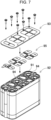
- the battery pack disclosed in the publication is provided with, as illustrated in the exploded perspective view of Fig. 7 and the enlarged cross-sectional view of Fig. 8 , gap closing wall 94 disposed around each electrode end face 91A of battery cells 91 in which the relief valve is provided. Gap closing wall 94 protrudes so as to abut against end face covering portion 93 of battery holder 92, which is provided around battery cells 91 and disposed opposite electrode end faces 91A of battery cells 91. End face covering portion 93 and gap closing wall 94 together form a closed structure for the space in which electrode end face 91A is exposed, to prevent the ejected substance from battery cell 91 from flowing out to an end face of adj acent battery cell 91.
- the battery pack shown in Figs. 7 and 8 allows gap closing wall 94 and end face covering portion 93 of battery holder 92 to clamp lead plate 95, so it is difficult to achieve a hermeticity sealed structure across lead plate 95. Therefore, it is difficult to reliably prevent the ejected substance from leaking from the gap between the lead plate 95 and causing adjacent battery cells 91 to catch fire. Further, it is extremely difficult for the battery pack in which a plurality of battery cells 91 are encased in an outer covering case to confine the high temperature, high pressure ejected substance, which is ejected from a battery cell in which the internal pressure is increased, within the case. The reason is that the ejected substance is gushed out from the battery cell at a high temperature exceeding 500°C.
- conventional common battery packs employ a structure such as to exhaust the high temperature, high pressure ejected substance, which is exhausted from a battery cell, to outside while reducing the energy, to prevent fire from spreading to another battery cell.
- This structure allows the ejected substance exhausted from each of the battery cells to be guided into the space that exists as a gap space inside the battery pack and to be exhausted outside. Therefore, the battery cells are allowed to communicate with each other at the exhaust side of the relief valve through the space inside the battery pack, so that the ejected substance exhausted from a certain battery cell can flows out to the relief valve side of another battery cell, causing fire to spread to the battery cell.
- the opening of the outer covering can is closed by a sealing plate.
- an insulating member called an insulating gasket
- the insulating gasket may soften and melt when exposed to the high temperature, high pressure ejected substance exhausted from the relief valve, causing a short-circuit between the outer covering can and the sealing plate.
- the short-circuit between the outer covering can and the sealing plate causes the battery cell to pass excessive short-circuit current and to generate abnormal heat, which may be a cause of spread of fire.
- the abnormal heat generation of the battery cell itself due to the excessive short-circuit current may be an inhibitory factor to ensure safety.
- An object of the present invention is to provide a battery pack that prevents the adverse effects due to the heat of the insulating gasket resulting from high temperature, high pressure ejected substance, and effectively prevents fire from spreading to battery cells, to be able to achieve high safety.
- a battery pack includes: a plurality of battery cells, each including an outer covering can and a sealing plate and being formed by securing an outer peripheral edge of the sealing plate to an opening of the outer covering can by a crimped part via an insulating gasket; an outer covering case containing the battery cells; and a protective ring member for the insulating gasket of one of the battery cells.
- the protective ring member includes an end face plate part covering a surface of the crimped part and a ribbed ring part covering an inner peripheral end edge of the crimped part, and the ribbed ring part is disposed between the end face plate part and the sealing plate, and includes a tip end surface close to a surface of the sealing plate.
- the battery pack as described above is able to achieve high safety by preventing the adverse effects due to the heat of the insulating gasket resulting from high temperature, high pressure ejected substance, and effectively preventing fire from spreading to battery cells.
- a battery pack includes: a plurality of battery cells, each including an outer covering can and a sealing plate and being formed by securing an outer peripheral edge of the sealing plate to an opening of the outer covering can by a crimped part via an insulating gasket; an outer covering case containing the battery cells; and a protective ring member for the insulating gasket of each of the battery cells, wherein: the protective ring member includes an end face plate part covering a surface of the crimped part and a ribbed ring part covering an inner peripheral end edge of the crimped part; and the ribbed ring part is disposed between the end face plate part and the sealing plate such as to bring a tip end surface thereof close to a surface of the sealing plate.
- the battery pack as described above has the feature of preventing the adverse effects caused by softening or melting of the insulating gasket of any of the battery cells due to the high temperature, high pressure ejected substance that is ejected when the battery cell has undergone thermal runaway, thereby preventing the thermal runaway of the battery cells from being induced, to ensure safety.
- a battery cell that has undergone thermal runaway exhausts high temperature, high pressure ejected substance.
- the battery cell in this condition causes an excessive short-circuit current to flow between the outer covering can and the sealing plate, generating heat due to Joule heat, which may be a cause of inducing thermal runaway.
- the battery pack as described above includes: a protective ring member for the insulating gasket of each battery cell; and the protective ring member includes an end face plate part covering a surface of the crimped part and a ribbed ring part covering an inner peripheral end edge of the crimped part; and the ribbed ring part is disposed between the end face plate part and the sealing plate such as to bring a tip end surface thereof close to a surface of the sealing plate.
- the ribbed ring part covers an exposed part of the insulating gasket to prevent a high temperature ejected substance from making contact with the insulating gasket.
- the insulating gasket that does not make contact with the high temperature ejected substance retains the outer covering can and the sealing plate in an electrically insulated condition without being affected by the damages caused by the heat of the ejected substance. Therefore, the battery pack as described above prevents the high temperature ejected substance exhausted from a battery cell that has undergone a thermal runaway from causing thermal damages to the insulating gasket of another battery cell disposed in the outer covering case. This prevents the adverse effect of thermal runaway in a battery cell that induces thermal runaway in another battery cell.
- the sealing plate may include a protruding electrode at a center of the sealing plate, and a ring-shaped flat surface, disposed outside the protruding electrode, on which the crimped part is stacked via the insulating gasket; a ring-shaped recess may be formed between the protruding electrode and the crimped part; and the ribbed ring part may protrude toward the ring-shaped recess to bring the tip end surface into contact with the ring-shaped flat surface.
- a battery pack according to another embodiment of the present invention may further include a battery holder arranging the battery cells at a fixed position, and the end face plate part may be integrally molded with the battery holder.
- the end face plate part and the ribbed ring part may be molded into an integral structure.
- the ribbed ring part may be a member separate from the end face plate part.
- the end face plate part and the ribbed ring part may be connected together in a fixed position by an engaging structure.
- the end face plate part and the ribbed ring part may be joined together.
- the ribbed ring part may be molded of a heat resistant material with a higher heat resistance temperature than the end face plate part.
- the ribbed ring part may be molded of a plastic with a higher heat resistance temperature than the end face plate part.
- the ribbed ring part may be made of an inorganic material.
- each of the elements that constitute the present invention may be embodied by an embodiment in which one member serves as a plurality of elements so that the plurality of elements are composed of the same member, or conversely, may be achieved in such an embodiment in which the function of one member is shared among a plurality of members.
- the battery pack of the present invention is mainly used as a power supply for motive power.
- This battery pack may be used, for example, a power supply for electrically-powered apparatuses that are driven by an electric motor, such as electric cleaners, electric power tools, electric power assisted bicycles, electric motorbikes, electric wheelchairs, electric tricycles, and electric carts.
- the present invention does not specifically limit the applications of the battery pack, but the battery pack may also be used as a power supply for electrical appliances other than the electrically-powered apparatuses, such as various electrical appliances used indoors or outdoors, for example, radio transceivers, lighting devices, and so forth, and as a motive power source and an auxiliary power source for transportation means.
- FIG. 1 shows a schematic cross-sectional view of the battery pack according to the first exemplary embodiment
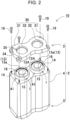
- Fig. 2 shows a schematic exploded perspective view of a battery assembly of the battery pack shown in Fig. 1
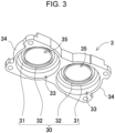
- Fig. 3 shows a bottom perspective view of an insulating cover of a battery holder of the battery assembly shown in Fig. 2 .
- FIG. 1 shows a schematic cross-sectional view of the battery pack according to the first exemplary embodiment
- FIG. 2 shows a schematic exploded perspective view of a battery assembly of the battery pack shown in Fig. 1
- Fig. 3 shows a bottom perspective view of an insulating cover of a battery holder of the battery assembly shown in Fig. 2 .
- FIG. 1 shows a schematic cross-sectional view of the battery pack according to the first exemplary embodiment
- Fig. 2 shows a schematic exploded perspective view of a battery assembly of the battery pack shown in Fig. 1
- Fig. 3 shows a bottom perspective view of an insulating cover of a battery
- the present invention does not particularly specify the number of battery cells 1 to be encased in outer covering case 9, and the number of battery cells 1 may be set to an optimum number in order to obtain a capacity that is suitable for the use.
- battery cells 1 may be connected in series or in parallel by connecting later-described lead plate 5 to electrodes 13 provided at respective ends of adj acent battery cells 1 the opposite ends of which are disposed on the same plane.
- Battery pack 100 described above includes outer covering case 9, a plurality of battery cells 1 encased in outer covering case 9, battery holder 2 arranging each of battery cells 1 at a fixed position, and lead plate 5 connected to ends of battery cells 1.
- Battery cell 1 is provided with positive and negative electrodes 13 at respective end faces.
- Battery holder 2 includes main body holder 4 and insulating covers 3 and 3' connected to the top and bottom of main body holder 4.
- Battery holder 2 retains a plurality of battery cells 1 in such an orientation parallel to each other along a longitudinal direction, and in such an orientation in which electrodes 13 provided at respective ends of battery cells 1 are arranged on the same plane.
- Insulating covers 3 and 3' are connected to the top and bottom of main body holder 4 to cover the end faces of battery cells 1 and arrange lead plate 5 at a fixed position.
- Lead plate 5 connects electrodes 13 of adjacent battery cells 1.
- Outer covering case 9 encases a plurality of battery cells 1 therein as battery assembly 10 arranged at a fixed position by battery holder 2.
- Outer covering case 9 is formed by molding a thermoplastic into a hollow box shape.
- Outer covering case 9 is provided with a relief opening (not shown) for exhausting the ejected substance from the relief valves of battery cells 1. Because outer covering case 9 is a closed structure and contains battery assembly 10 inside, the ejected substance flows into the gap space inside outer covering case 9 and causes thermal damages to insulating gaskets 15 of battery cells 1.
- Insulating gasket 15 is disposed between crimped part 14 of outer covering can 11 and sealing plate 12 in order to electrically insulate outer covering can 11 and sealing plate 12, which serve as the positive and negative electrodes.
- battery cell 1 a non-aqueous electrolyte secondary battery, such as a lithium-ion battery that shows high energy efficiency, is suitable.
- battery cell 1 is not limited to a lithium-ion battery but may be any type of secondary battery in which the opening of outer covering can 11 is crimped to secure sealing plate 12 via insulating gasket 15 and a relief valve is used to exhaust the ejected substance when the internal pressure increases.
- Battery cell 1 is produced by encasing an electrode assembly into outer covering can 11 made of a metal, filling an electrolyte solution therein, and air-tightly closing the opening of outer covering can 11 with sealing plate 12.
- Battery cell 1 is provided with positive and negative electrodes 13 at opposite ends.
- Battery cell 1 uses electrodes provided on opposite end faces, i.e., a bottom face of outer covering can 11 and an electrode provided at a central part of sealing plate 12, as positive and negative electrodes 13.
- protruding electrode 13a provided on sealing plate 12 and bottom face electrode 13b of outer covering can 11 are provided at opposite ends as positive and negative electrodes 13.
- Outer covering can 11 is processed into a tubular shape with its bottom closed by press working a metal plate.
- Sealing plate 12 is produced by press working a metal plate into a shape provided with protruding electrode 13a at its central part.
- Sealing plate 12 is provided with a relief valve (not shown) inside.
- sealing plate 12 is provided with a relief opening (not shown) around protruding electrode 13a so that the ejected substance exhausted from the relief valve that is opened can be exhausted outside.
- the relief valve is allowed to open to exhaust the ejected substance when the internal pressure exceeds a threshold value.
- the relief valve that is opened exhausts the high temperature ejected substance.
- a cylindrical battery is suitable. The reason is that, by crimping the entire circumference of the opening of outer covering can 11 and insulating with insulating gasket 15, the cylindrical battery can be hermetically sealed air-tightly by sealing plate 12. Because there is a potential difference between outer covering can 11 and sealing plate 12, which are made of a metal plate, insulating gasket 15 is fitted between crimped part 14 of outer covering can 11 and sealing plate 12 to electrically insulate them. Because outer covering can 11 is hermetically sealed by sealing plate 12 by crimping the opening, insulating gasket 15 is brought into an interposed condition between crimped part 14 and sealing plate 12.
- Outer covering can 11 with its opening edge being bent inward by the crimping process allows crimped part 14 to press insulating gasket 15 against the surface of sealing plate 12, whereby outer covering can 11 and sealing plate 12 are electrically insulated and hermetically sealed.
- Sealing plate 12 shown in Fig. 1 is formed by press working a metal plate so that protruding electrode 13a is provided at its central part and the outside of protruding electrode 13a is formed into ring-shaped flat surface 12A.
- the outer peripheral edge part of ring-shaped flat surface 12A sandwiches insulating gasket 15 between it and outer covering can 11, which is pressed by crimped part 14 to hermetically seal outer covering can 11.
- Battery cell 1 as described above uses electrode 13 of sealing plate 12 as protruding electrode 13a, but battery cell 1 does not necessarily use electrode 13 of sealing plate 12 as protruding electrode 13a.
- electrode 13 of sealing plate 12 of battery cell 1 may be flat surface electrode 13c.
- This battery cell 1 is likewise hermetically sealed by sandwiching insulating gasket 15 between the outer peripheral edge part of sealing plate 12 and outer covering can 11, and pressing it with crimped part 14.
- Insulating gasket 15 electrically insulates outer covering can 11 and sealing plate 12 from each other and hermetically seals them air-tightly. Insulating gasket 15 undergoes elastic deformation by being pressed by crimped part 14 and makes in intimate contact with crimped part 14 and the surface of sealing plate 12, to hermetically seal outer covering can 11 and sealing plate 12. Insulating gasket 15 is required to have heat resistance, electrolyte resistance, and electrically insulative properties. For insulating gasket 15 that achieves such physical properties, super engineering plastics, such as PPS and PTFE, are used. However, even with such insulating gasket 15 with good heat resistance, it is extremely difficult to achieve physical properties that can withstand the temperature of the ejected substance exhausted from the relief valve.
- super engineering plastics such as PPS and PTFE
- Insulating gasket 15 separates crimped part 14 and sealing plate 12 from each other so as not to come into contact, to insulate them from each other, so insulating gasket 15 is disposed in a gap provided between crimped part 14 and sealing plate 12, which means that it is impossible to completely eliminate the exposed part thereof.
- insulating gasket 15 undergoes thermal damages and is consequently unable to maintain crimped part 14 and sealing plate 12 to be in an insulated condition.
- An excessive short-circuit current can flow between outer covering can 11 and sealing plate 12 that are unable to be kept in an insulated condition by insulating gasket 15, which may deteriorate safety.
- Battery holder 2 contains battery cells 1 inside and arranges them in a fixed position.
- Battery holder 2 shown in Figs. 1 and 2 includes main body holder 4 and insulating covers 3 and 3', which are separately molded of a thermoplastic, so that insulating covers 3 and 3' are connected to the top and bottom of main body holder 4, to arrange a plurality of battery cells 1 in a fixed position.
- Main body holder 4 arranges a plurality of battery cells 1 in a parallel posture to each other by inserting battery cells 1 in a plurality of cell-containing compartments 41, which are formed in a parallel posture.
- insulating covers 3 and 3' are secured to main body holder 4, so that electrodes 13 that are provided on opposite ends of battery cells 1 are arranged in the same planes.
- Insulating covers 3 and 3' shown in Fig. 2 are secured to main body holder 4 with fastening screws 19 that penetrate corner parts. Fastening screws 19 penetrate the four corner parts of insulating cover 3 and are screwed into main body holder 4, to secure insulating covers 3 and 3' at fixed positions on main body holder 4.
- main body holder 4 shown in Fig. 2 is joined to insulating covers 3 and 3' and arranges battery cells 1 in a fixed position.
- Main body holder 4 retains inserted battery cells 1 at its middle part and retains them in a fixed position.
- Insulating covers 3 and 3' electrically insulate the end faces of battery cells 1 inserted in main body holder 4 and arrange lead plate 5 at a fixed position. Insulating covers 3 and 3' are provided with connection windows 35, for connecting with lead plate 5, opened at the positions opposed to the end faces of battery cells 1.
- Insulating cover 3 shown in the bottom perspective view of Fig. 3 is provided with engaging recesses 33 into which the end parts of battery cells 1 are inserted.
- Engaging recess 33 is a circular-shaped recess such that an end part of a cylindrical battery is engaged therein, which retains the outer circumferential surface of the end part of battery cell 1.
- Main body holder 4 is, as illustrated in Figs. 1 and 2 , provided with cell-containing compartments 41 in which battery cells 1 are inserted.
- the openings of engaging recesses 33 are disposed at opposite positions to the openings of cell-containing compartments 41 of main body holder 4.
- battery pack 100 which uses cylindrical batteries for battery cells 1
- cell-containing compartments 41 of main body holder 4 and engaging recesses 33 are formed in a cylindrical shape.
- Battery holder 2 shown in Figs. 1 and 2 is such that battery cells 1 are inserted in cell-containing compartments 41 of main body holder 4 to be arranged in a parallel posture to each other, and respective opposite ends of battery cells 1 are guided into engaging recesses 33 of insulating covers 3 and 3' to be arranged in a fixed position.
- battery holder 2 is not limited to this configuration.
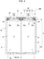
- Battery holder 2 may have such a configuration that, as illustrated in Fig. 4 , bottom insulating cover 3' is integrated with main body holder 4 and only the top opening of closed-bottomed main body holder 4X is covered by insulating cover 3.
- Insulating cover 3 is provided with protective ring member 30 integrally molded therewith, in order to prevent damages to the insulating member of battery cells 1, which results from the ejected substance.
- Insulating cover 3 includes protective ring member 30 provided opposite the end faces of battery cells 1.
- Protective ring member 30 includes end face plate part 31, which covers the surface of crimped part 14 of battery cell 1, and ribbed ring part 32, which protrudes from end face plate part 31 toward the surface of sealing plate 12.
- Ribbed ring part 32 protrudes from end face plate part 31 toward sealing plate 12 and brings tip end surface 32a close to the surface of sealing plate 12.
- Tip end surface 32a of ribbed ring part 32 is brought close to the surface of sealing plate 12, preferably so as to be in contact with the surface of sealing plate 12.
- Protective ring member 30 allows end face plate part 31 and ribbed ring part 32 to extend from the surface of crimped part 14 to the surface of sealing plate 12, to protect insulating gasket 15.
- protective ring member 30 allows ribbed ring part 32 and end face plate part 31 to cover the exposed part of insulating gasket 15 to prevent the adverse effects caused by damages to insulating gasket 15, which results from the ejected substance.
- protruding electrode 13a is provided at a central part of sealing plate 12
- ring-shaped flat surface 12A is provided on the outer peripheral part of protruding electrode 13a
- insulating gasket 15 and crimped part 14 are stacked on the outer peripheral part of ring-shaped flat surface 12A. Therefore, ring-shaped recess 16 is provided between protruding electrode 13a and crimped part 14. Ribbed ring part 32 protrudes toward ring-shaped recess 16 and brings protruding tip end surface 32a into contact with ring-shaped flat surface 12A.
- circumferential wall part 34 which has an inner shape such as to fit along the outer circumference of battery cell 1, and end face plate part 31 are formed in an integral structure, and engaging recess 33 for guiding battery cell 1 is provided inside circumferential wall part 34 and end face plate part 31.
- the inner circumference of end face plate part 31 is provided with ribbed ring part 32 to be an integral structure.
- This insulating cover 3 is provided with engaging recess 33 for battery cell 1, and end face plate part 31 and ribbed ring part 32 are integrally molded with each other.
- end face plate part 31 and ribbed ring part 32 are disposed at a fixed position relative to battery cell 1, so that relative misalignment between protective ring member 30 and battery cell 1 can be prevented.
- protective ring member 30 is able to protect insulating gasket 15 effectively from the ejected substance.
- Insulating cover 3 described above allows battery cell 1 to be inserted in engaging recess 33 to arrange battery cell 1 in a fixed position.
- insulating cover 3 may prevent relative misalignment with battery cell 1 by being disposed at a fixed position on main body holder 4 using fastening screws or an engaging structure, not shown, without providing engaging recess 33 in which battery cell 1 is inserted. Accordingly, it is also possible to secure insulating cover 3 at a fixed position on main body holder 4 without providing engaging recess 33.
- Battery holder 2 as described above uses insulating covers 3 and 3' and main body holder 4 as separate members, and is assembled so that insulating covers 3 and 3' are joined to main body holder 4 in which battery cells 1 are inserted.
- insulating covers 3 and 3' and split main body holders 4A and 4B may be molded into an integral structure, as in battery pack 300 shown in Fig. 5 . This structure may be assembled by inserting half of battery cells 1 into cell-containing compartments 41 of one of split battery holder 2A, which forms battery holder 2, then inserting the other half of battery cells 1 into cell-containing compartments 41 of the other one of split battery holder 2B, and joining the pair of split battery holders 2A and 2B together.
- Insulating cover 3 that is molded in an integral structure with split battery holder 2A may be provided with protective ring member 30 in an integral structure, and may connect split battery holder 2A to battery cells 1 with an engaging structure to arrange protective ring member 30 at a fixed position on battery cells 1.
- insulating cover 3 may also be such that end face plate part 31 is molded in an integral structure therewith while ribbed ring part 32 may be molded as a separate member.
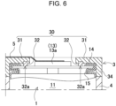
- This ribbed ring part 32 is, as illustrated in Fig. 6 , molded as a separate member also from battery holder 2.
- Ribbed ring part 32 that is a separate member may be molded of a heat resistant material having a higher heat resistance temperature than end face plate part 31.
- Ribbed ring part 32 that is a separate member may be molded of, for example, a plastic having a higher heat resistance temperature than end face plate part 31, or alternatively, may be produced of an electrically insulative inorganic material, such as metal, metallic compound, mica, or ceramic, that is rendered to have an electrically insulating structure by a surface insulation treatment or laminating an insulating material.
- ribbed ring part 32 that is a separate member as described above may be joined to a fixed position on end face plate part 31 by an engaging structure during assembly.
- ribbed ring part 32 may be joined to end face plate part 31 by adhesive bonding, or may be joined to a fixed position on end face plate part 31 by bonding with a double-sided adhesive tape or the like.
- ribbed ring part 32 when ribbed ring part 32 is composed of a different material from that of end face plate part 31, ribbed ring part 32 and end face plate part 31 may not necessarily be separate members from each other and ribbed ring part 32 may be formed in an integral structure with end face plate part 31.
- ribbed ring part 32 may be molded of a plastic having a higher heat resistance temperature than end face plate part 31 by double molding to form an integral structure. It is also possible to achieve excellent heat resistance while ribbed ring part 32 is molded into an integral structure with end face plate part 31 by insert molding the previously-mentioned inorganic material in the resin molding for ribbed ring part 32. As described above, it is possible to perform assembling easily and simply while achieving excellent heat resistance by constructing ribbed ring part 32 from a heat resistant material having a high heat resistance temperature and forming an integral structure with end face plate part 31.
- Lead plate 5 is set at a fixed position on insulating cover 3 and is connected to electrodes 13 of adjacent battery cells 1.
- adjacent battery cells 1 are connected in parallel, so respective opposite ends of lead plate 5 are connected to protruding electrodes 13a, which are electrodes 13 of adjacent battery cells 1.
- Lead plate 5 is connected to electrodes 13 of adjacent battery cells 1 by a welding technique, such as spot welding or laser welding.
- a welding technique such as spot welding or laser welding.
- metal plates such as iron plate surface-plated with nickel or the like, nickel plate, copper plate, aluminum plate, and the like.
- the battery pack according to the present invention is suitably applied to a power supply for various applications, as a battery pack that inhibits the ejected substance from the opened relief valve of a battery cell from causing thermal damages to other battery cells and thereby enhances safety.
Landscapes
- Chemical & Material Sciences (AREA)
- Chemical Kinetics & Catalysis (AREA)
- Electrochemistry (AREA)
- General Chemical & Material Sciences (AREA)
- Inorganic Chemistry (AREA)
- Battery Mounting, Suspending (AREA)
- Connection Of Batteries Or Terminals (AREA)
- Sealing Battery Cases Or Jackets (AREA)
Abstract
Description
- The present invention relates to battery packs in which a plurality of battery cells are disposed in an outer covering case.
- Secondary batteries, such as lithium-ion batteries, which have high electromotive force and high energy density, generate gas inside battery cells and increases the internal pressure due to overcharge, overdischarge, internal short circuit, or external short circuit, so they are provided with a relief valve to prevent its outer covering can from rapturing. The gas ejected from the opened relief valve has a high temperature, so it may heat up adjacent battery cells and cause them to catch fire.
- A battery pack has been proposed that has a structure of preventing the adverse effects of the high-temperature ejected substance exhausted from a heated battery cell that causes adjacent battery cells to catch fire (for example, see PTL 1).
- The battery pack disclosed in the publication is provided with, as illustrated in the exploded perspective view of
Fig. 7 and the enlarged cross-sectional view ofFig. 8 ,gap closing wall 94 disposed around eachelectrode end face 91A ofbattery cells 91 in which the relief valve is provided.Gap closing wall 94 protrudes so as to abut against endface covering portion 93 ofbattery holder 92, which is provided aroundbattery cells 91 and disposed oppositeelectrode end faces 91A ofbattery cells 91. Endface covering portion 93 andgap closing wall 94 together form a closed structure for the space in whichelectrode end face 91A is exposed, to prevent the ejected substance frombattery cell 91 from flowing out to an end face of adjacent battery cell 91. - PTL 1:
Japanese Patent Unexamined Publication No. 2020-166991 - The battery pack shown in
Figs. 7 and8 allowsgap closing wall 94 and endface covering portion 93 ofbattery holder 92 toclamp lead plate 95, so it is difficult to achieve a hermeticity sealed structure acrosslead plate 95. Therefore, it is difficult to reliably prevent the ejected substance from leaking from the gap between thelead plate 95 and causingadjacent battery cells 91 to catch fire. Further, it is extremely difficult for the battery pack in which a plurality ofbattery cells 91 are encased in an outer covering case to confine the high temperature, high pressure ejected substance, which is ejected from a battery cell in which the internal pressure is increased, within the case. The reason is that the ejected substance is gushed out from the battery cell at a high temperature exceeding 500°C. For this reason, conventional common battery packs employ a structure such as to exhaust the high temperature, high pressure ejected substance, which is exhausted from a battery cell, to outside while reducing the energy, to prevent fire from spreading to another battery cell. This structure allows the ejected substance exhausted from each of the battery cells to be guided into the space that exists as a gap space inside the battery pack and to be exhausted outside. Therefore, the battery cells are allowed to communicate with each other at the exhaust side of the relief valve through the space inside the battery pack, so that the ejected substance exhausted from a certain battery cell can flows out to the relief valve side of another battery cell, causing fire to spread to the battery cell. - In each of the battery cells encased in the outer covering case, the opening of the outer covering can is closed by a sealing plate. In order to electrically insulate the outer covering can and the sealing plate from each other, an insulating member, called an insulating gasket, is interposed between the sealing plate and the crimped part of the outer covering can, to hermetically seal the outer covering can and the sealing plate. The insulating gasket may soften and melt when exposed to the high temperature, high pressure ejected substance exhausted from the relief valve, causing a short-circuit between the outer covering can and the sealing plate. The short-circuit between the outer covering can and the sealing plate causes the battery cell to pass excessive short-circuit current and to generate abnormal heat, which may be a cause of spread of fire. Particularly in an environment exposed to high temperature, high pressure ejected substance in which spread of fire easily occurs, the abnormal heat generation of the battery cell itself due to the excessive short-circuit current may be an inhibitory factor to ensure safety.
- The present invention has been developed to solve the foregoing and other problems. An object of the present invention is to provide a battery pack that prevents the adverse effects due to the heat of the insulating gasket resulting from high temperature, high pressure ejected substance, and effectively prevents fire from spreading to battery cells, to be able to achieve high safety.
- According to an embodiment of the present invention, a battery pack includes: a plurality of battery cells, each including an outer covering can and a sealing plate and being formed by securing an outer peripheral edge of the sealing plate to an opening of the outer covering can by a crimped part via an insulating gasket; an outer covering case containing the battery cells; and a protective ring member for the insulating gasket of one of the battery cells. The protective ring member includes an end face plate part covering a surface of the crimped part and a ribbed ring part covering an inner peripheral end edge of the crimped part, and the ribbed ring part is disposed between the end face plate part and the sealing plate, and includes a tip end surface close to a surface of the sealing plate.
- The battery pack as described above is able to achieve high safety by preventing the adverse effects due to the heat of the insulating gasket resulting from high temperature, high pressure ejected substance, and effectively preventing fire from spreading to battery cells.
-
-
Fig. 1 is a schematic cross-sectional view of a battery pack according to an exemplary embodiment of the present invention. -
Fig. 2 is an schematic exploded perspective view of a battery assembly of the battery pack shown inFig. 1 . -
Fig. 3 is a bottom perspective view of an insulating cover of a battery holder shown inFig. 2 . -
Fig. 4 is a schematic cross-sectional view of a battery pack according to another exemplary embodiment of the present invention. -
Fig. 5 is a schematic cross-sectional view of a battery pack according to still another exemplary embodiment of the present invention. -
Fig. 6 is a schematic enlarged cross-sectional view of a battery pack according to yet another exemplary embodiment of the present invention. -
Fig. 7 is an exploded perspective view of a conventional battery pack. -
Fig. 8 is an enlarged cross-sectional view of the battery pack shown inFig. 7 . - In one embodiment of the present invention, a battery pack includes: a plurality of battery cells, each including an outer covering can and a sealing plate and being formed by securing an outer peripheral edge of the sealing plate to an opening of the outer covering can by a crimped part via an insulating gasket; an outer covering case containing the battery cells; and a protective ring member for the insulating gasket of each of the battery cells, wherein: the protective ring member includes an end face plate part covering a surface of the crimped part and a ribbed ring part covering an inner peripheral end edge of the crimped part; and the ribbed ring part is disposed between the end face plate part and the sealing plate such as to bring a tip end surface thereof close to a surface of the sealing plate.
- The battery pack as described above has the feature of preventing the adverse effects caused by softening or melting of the insulating gasket of any of the battery cells due to the high temperature, high pressure ejected substance that is ejected when the battery cell has undergone thermal runaway, thereby preventing the thermal runaway of the battery cells from being induced, to ensure safety. A battery cell that has undergone thermal runaway exhausts high temperature, high pressure ejected substance. When the ejected substance makes contact with the insulating gasket, which hermetically seals the outer covering can and the sealing plate air tight in an electrically insulated condition, the insulate undergoes thermal damages and is consequently unable to keep the outer covering can and the sealing plate in an electrically insulated condition. The battery cell in this condition causes an excessive short-circuit current to flow between the outer covering can and the sealing plate, generating heat due to Joule heat, which may be a cause of inducing thermal runaway. The battery pack as described above includes: a protective ring member for the insulating gasket of each battery cell; and the protective ring member includes an end face plate part covering a surface of the crimped part and a ribbed ring part covering an inner peripheral end edge of the crimped part; and the ribbed ring part is disposed between the end face plate part and the sealing plate such as to bring a tip end surface thereof close to a surface of the sealing plate. The ribbed ring part covers an exposed part of the insulating gasket to prevent a high temperature ejected substance from making contact with the insulating gasket. The insulating gasket that does not make contact with the high temperature ejected substance retains the outer covering can and the sealing plate in an electrically insulated condition without being affected by the damages caused by the heat of the ejected substance. Therefore, the battery pack as described above prevents the high temperature ejected substance exhausted from a battery cell that has undergone a thermal runaway from causing thermal damages to the insulating gasket of another battery cell disposed in the outer covering case. This prevents the adverse effect of thermal runaway in a battery cell that induces thermal runaway in another battery cell.
- In a battery pack according to another embodiment of the present invention, the sealing plate may include a protruding electrode at a center of the sealing plate, and a ring-shaped flat surface, disposed outside the protruding electrode, on which the crimped part is stacked via the insulating gasket; a ring-shaped recess may be formed between the protruding electrode and the crimped part; and the ribbed ring part may protrude toward the ring-shaped recess to bring the tip end surface into contact with the ring-shaped flat surface.
- A battery pack according to another embodiment of the present invention may further include a battery holder arranging the battery cells at a fixed position, and the end face plate part may be integrally molded with the battery holder.
- In a battery pack according to another embodiment of the present invention, the end face plate part and the ribbed ring part may be molded into an integral structure.
- In a battery pack according to another embodiment of the present invention, the ribbed ring part may be a member separate from the end face plate part.
- In a battery pack according to another embodiment of the present invention, the end face plate part and the ribbed ring part may be connected together in a fixed position by an engaging structure.
- In a battery pack according to another embodiment of the present invention, the end face plate part and the ribbed ring part may be joined together.
- In a battery pack according to another embodiment of the present invention, the ribbed ring part may be molded of a heat resistant material with a higher heat resistance temperature than the end face plate part.
- In a battery pack according to another embodiment of the present invention, the ribbed ring part may be molded of a plastic with a higher heat resistance temperature than the end face plate part.
- In a battery pack according to another embodiment of the present invention, the ribbed ring part may be made of an inorganic material.
- Hereinbelow, exemplary embodiments of the present invention are described with reference to the drawings. It should be noted, however, that the following exemplary embodiments are merely examples for embodying the technical ideas of the present invention, and the present invention is not limited to the following exemplary embodiments. In addition, the present description is in no way provided for limiting the members shown in the claims to the members illustrated in the exemplary embodiments. Moreover, the dimensions, materials, shapes, relative arrangements, and the like of parts and elements described in the following exemplary embodiments are merely illustrative examples, and should not be construed to limit the scope of the invention, unless specifically stated otherwise. Furthermore, the sizes of some elements, their positional relationships, and so forth shown in the drawings may be exaggerated for clarity in illustration. In the following description, like names and symbols refer to same or similar elements, and detailed description thereof will not be given as appropriate. Furthermore, each of the elements that constitute the present invention may be embodied by an embodiment in which one member serves as a plurality of elements so that the plurality of elements are composed of the same member, or conversely, may be achieved in such an embodiment in which the function of one member is shared among a plurality of members.
- The battery pack of the present invention is mainly used as a power supply for motive power. This battery pack may be used, for example, a power supply for electrically-powered apparatuses that are driven by an electric motor, such as electric cleaners, electric power tools, electric power assisted bicycles, electric motorbikes, electric wheelchairs, electric tricycles, and electric carts. However, the present invention does not specifically limit the applications of the battery pack, but the battery pack may also be used as a power supply for electrical appliances other than the electrically-powered apparatuses, such as various electrical appliances used indoors or outdoors, for example, radio transceivers, lighting devices, and so forth, and as a motive power source and an auxiliary power source for transportation means.
- A battery pack according to the first exemplary embodiment of the present invention is shown in
Figs. 1 to 3 . In these drawings,Fig. 1 shows a schematic cross-sectional view of the battery pack according to the first exemplary embodiment,Fig. 2 shows a schematic exploded perspective view of a battery assembly of the battery pack shown inFig. 1 , andFig. 3 shows a bottom perspective view of an insulating cover of a battery holder of the battery assembly shown inFig. 2 . These drawings illustratebattery pack 100 in which twobattery cells 1 are encased inouter covering case 9. However, the present invention does not particularly specify the number ofbattery cells 1 to be encased inouter covering case 9, and the number ofbattery cells 1 may be set to an optimum number in order to obtain a capacity that is suitable for the use. Inbattery pack 100 in which a large number ofbattery cells 1 are encased inouter covering case 9,battery cells 1 may be connected in series or in parallel by connecting later-describedlead plate 5 toelectrodes 13 provided at respective ends of adj acentbattery cells 1 the opposite ends of which are disposed on the same plane. -
Battery pack 100 described above includesouter covering case 9, a plurality ofbattery cells 1 encased inouter covering case 9,battery holder 2 arranging each ofbattery cells 1 at a fixed position, andlead plate 5 connected to ends ofbattery cells 1.Battery cell 1 is provided with positive andnegative electrodes 13 at respective end faces.Battery holder 2 includesmain body holder 4 and insulatingcovers 3 and 3' connected to the top and bottom ofmain body holder 4.Battery holder 2 retains a plurality ofbattery cells 1 in such an orientation parallel to each other along a longitudinal direction, and in such an orientation in whichelectrodes 13 provided at respective ends ofbattery cells 1 are arranged on the same plane. Insulating covers 3 and 3' are connected to the top and bottom ofmain body holder 4 to cover the end faces ofbattery cells 1 and arrangelead plate 5 at a fixed position. Leadplate 5 connectselectrodes 13 ofadjacent battery cells 1. -
Outer covering case 9 encases a plurality ofbattery cells 1 therein asbattery assembly 10 arranged at a fixed position bybattery holder 2.Outer covering case 9 is formed by molding a thermoplastic into a hollow box shape.Outer covering case 9 is provided with a relief opening (not shown) for exhausting the ejected substance from the relief valves ofbattery cells 1. Becauseouter covering case 9 is a closed structure and containsbattery assembly 10 inside, the ejected substance flows into the gap space insideouter covering case 9 and causes thermal damages to insulatinggaskets 15 ofbattery cells 1. Insulatinggasket 15 is disposed betweencrimped part 14 of outer covering can 11 and sealingplate 12 in order to electrically insulate outer covering can 11 and sealingplate 12, which serve as the positive and negative electrodes. - For
battery cell 1, a non-aqueous electrolyte secondary battery, such as a lithium-ion battery that shows high energy efficiency, is suitable. However,battery cell 1 is not limited to a lithium-ion battery but may be any type of secondary battery in which the opening of outer covering can 11 is crimped to secure sealingplate 12 via insulatinggasket 15 and a relief valve is used to exhaust the ejected substance when the internal pressure increases.Battery cell 1 is produced by encasing an electrode assembly into outer covering can 11 made of a metal, filling an electrolyte solution therein, and air-tightly closing the opening of outer covering can 11 with sealingplate 12.Battery cell 1 is provided with positive andnegative electrodes 13 at opposite ends.Battery cell 1 uses electrodes provided on opposite end faces, i.e., a bottom face of outer covering can 11 and an electrode provided at a central part of sealingplate 12, as positive andnegative electrodes 13. In each ofbattery cells 1 shown inFig. 1 , protrudingelectrode 13a provided on sealingplate 12 andbottom face electrode 13b of outer covering can 11 are provided at opposite ends as positive andnegative electrodes 13. - Outer covering can 11 is processed into a tubular shape with its bottom closed by press working a metal plate. Sealing
plate 12 is produced by press working a metal plate into a shape provided with protrudingelectrode 13a at its central part. Sealingplate 12 is provided with a relief valve (not shown) inside. Furthermore, sealingplate 12 is provided with a relief opening (not shown) around protrudingelectrode 13a so that the ejected substance exhausted from the relief valve that is opened can be exhausted outside. In order to prevent the rapture due to an internal pressure increase, the relief valve is allowed to open to exhaust the ejected substance when the internal pressure exceeds a threshold value. The relief valve that is opened exhausts the high temperature ejected substance. - For
battery cell 1, a cylindrical battery is suitable. The reason is that, by crimping the entire circumference of the opening of outer covering can 11 and insulating with insulatinggasket 15, the cylindrical battery can be hermetically sealed air-tightly by sealingplate 12. Because there is a potential difference between outer covering can 11 and sealingplate 12, which are made of a metal plate, insulatinggasket 15 is fitted betweencrimped part 14 of outer covering can 11 and sealingplate 12 to electrically insulate them. Because outer covering can 11 is hermetically sealed by sealingplate 12 by crimping the opening, insulatinggasket 15 is brought into an interposed condition betweencrimped part 14 and sealingplate 12. Outer covering can 11 with its opening edge being bent inward by the crimping process allows crimpedpart 14 to press insulatinggasket 15 against the surface of sealingplate 12, whereby outer covering can 11 and sealingplate 12 are electrically insulated and hermetically sealed. Sealingplate 12 shown inFig. 1 is formed by press working a metal plate so that protrudingelectrode 13a is provided at its central part and the outside of protrudingelectrode 13a is formed into ring-shapedflat surface 12A. The outer peripheral edge part of ring-shapedflat surface 12A sandwiches insulatinggasket 15 between it and outer covering can 11, which is pressed bycrimped part 14 to hermetically seal outer covering can 11. -
Battery cell 1 as described above uses electrode 13 of sealingplate 12 as protrudingelectrode 13a, butbattery cell 1 does not necessarily useelectrode 13 of sealingplate 12 as protrudingelectrode 13a. As inbattery pack 200 shown inFig. 4 , it is possible thatelectrode 13 of sealingplate 12 ofbattery cell 1 may beflat surface electrode 13c. Thisbattery cell 1 is likewise hermetically sealed by sandwiching insulatinggasket 15 between the outer peripheral edge part of sealingplate 12 and outer covering can 11, and pressing it withcrimped part 14. - Insulating
gasket 15 electrically insulates outer covering can 11 and sealingplate 12 from each other and hermetically seals them air-tightly. Insulatinggasket 15 undergoes elastic deformation by being pressed bycrimped part 14 and makes in intimate contact withcrimped part 14 and the surface of sealingplate 12, to hermetically seal outer covering can 11 and sealingplate 12. Insulatinggasket 15 is required to have heat resistance, electrolyte resistance, and electrically insulative properties. For insulatinggasket 15 that achieves such physical properties, super engineering plastics, such as PPS and PTFE, are used. However, even with such insulatinggasket 15 with good heat resistance, it is extremely difficult to achieve physical properties that can withstand the temperature of the ejected substance exhausted from the relief valve. Insulatinggasket 15 separates crimpedpart 14 and sealingplate 12 from each other so as not to come into contact, to insulate them from each other, so insulatinggasket 15 is disposed in a gap provided betweencrimped part 14 and sealingplate 12, which means that it is impossible to completely eliminate the exposed part thereof. When this exposed part of insulatinggasket 15 is exposed to a high temperature ejected substance, insulatinggasket 15 undergoes thermal damages and is consequently unable to maintaincrimped part 14 and sealingplate 12 to be in an insulated condition. An excessive short-circuit current can flow between outer covering can 11 and sealingplate 12 that are unable to be kept in an insulated condition by insulatinggasket 15, which may deteriorate safety. -
Battery holder 2 containsbattery cells 1 inside and arranges them in a fixed position.Battery holder 2 shown inFigs. 1 and2 includesmain body holder 4 and insulatingcovers 3 and 3', which are separately molded of a thermoplastic, so that insulatingcovers 3 and 3' are connected to the top and bottom ofmain body holder 4, to arrange a plurality ofbattery cells 1 in a fixed position.Main body holder 4 arranges a plurality ofbattery cells 1 in a parallel posture to each other by insertingbattery cells 1 in a plurality of cell-containingcompartments 41, which are formed in a parallel posture. Inbattery holder 2, insulatingcovers 3 and 3' are secured tomain body holder 4, so thatelectrodes 13 that are provided on opposite ends ofbattery cells 1 are arranged in the same planes. - Insulating covers 3 and 3' shown in
Fig. 2 are secured tomain body holder 4 withfastening screws 19 that penetrate corner parts. Fastening screws 19 penetrate the four corner parts of insulatingcover 3 and are screwed intomain body holder 4, to secureinsulating covers 3 and 3' at fixed positions onmain body holder 4. Afterbattery cells 1 are inserted,main body holder 4 shown inFig. 2 is joined to insulatingcovers 3 and 3' and arrangesbattery cells 1 in a fixed position.Main body holder 4 retains insertedbattery cells 1 at its middle part and retains them in a fixed position. Insulating covers 3 and 3' electrically insulate the end faces ofbattery cells 1 inserted inmain body holder 4 and arrangelead plate 5 at a fixed position. Insulating covers 3 and 3' are provided withconnection windows 35, for connecting withlead plate 5, opened at the positions opposed to the end faces ofbattery cells 1. - Insulating
cover 3 shown in the bottom perspective view ofFig. 3 is provided with engagingrecesses 33 into which the end parts ofbattery cells 1 are inserted. Engagingrecess 33 is a circular-shaped recess such that an end part of a cylindrical battery is engaged therein, which retains the outer circumferential surface of the end part ofbattery cell 1.Main body holder 4 is, as illustrated inFigs. 1 and2 , provided with cell-containingcompartments 41 in whichbattery cells 1 are inserted. The openings of engagingrecesses 33 are disposed at opposite positions to the openings of cell-containingcompartments 41 ofmain body holder 4. Inbattery pack 100, which uses cylindrical batteries forbattery cells 1, cell-containingcompartments 41 ofmain body holder 4 and engagingrecesses 33 are formed in a cylindrical shape.Battery holder 2 shown inFigs. 1 and2 is such thatbattery cells 1 are inserted in cell-containingcompartments 41 ofmain body holder 4 to be arranged in a parallel posture to each other, and respective opposite ends ofbattery cells 1 are guided into engagingrecesses 33 of insulatingcovers 3 and 3' to be arranged in a fixed position. However, according to the present invention,battery holder 2 is not limited to this configuration.Battery holder 2 may have such a configuration that, as illustrated inFig. 4 , bottom insulating cover 3' is integrated withmain body holder 4 and only the top opening of closed-bottomedmain body holder 4X is covered by insulatingcover 3. - Insulating
cover 3 is provided withprotective ring member 30 integrally molded therewith, in order to prevent damages to the insulating member ofbattery cells 1, which results from the ejected substance. Insulatingcover 3 includesprotective ring member 30 provided opposite the end faces ofbattery cells 1.Protective ring member 30 includes endface plate part 31, which covers the surface ofcrimped part 14 ofbattery cell 1, and ribbedring part 32, which protrudes from endface plate part 31 toward the surface of sealingplate 12.Ribbed ring part 32 protrudes from endface plate part 31 toward sealingplate 12 and bringstip end surface 32a close to the surface of sealingplate 12.Tip end surface 32a of ribbedring part 32 is brought close to the surface of sealingplate 12, preferably so as to be in contact with the surface of sealingplate 12.Protective ring member 30 allows endface plate part 31 and ribbedring part 32 to extend from the surface ofcrimped part 14 to the surface of sealingplate 12, to protect insulatinggasket 15. - Because insulating
gasket 15 is exposed in the gap betweencrimped part 14 and sealingplate 12, the exposed part can be softened or melted when exposed to the ejected substance, which can be a cause of short-circuit between outer covering can 11 and sealingplate 12. However,protective ring member 30 allows ribbedring part 32 and endface plate part 31 to cover the exposed part of insulatinggasket 15 to prevent the adverse effects caused by damages to insulatinggasket 15, which results from the ejected substance. - In
battery cells 1 shown inFig. 1 , protrudingelectrode 13a is provided at a central part of sealingplate 12, ring-shapedflat surface 12A is provided on the outer peripheral part of protrudingelectrode 13a, and insulatinggasket 15 and crimpedpart 14 are stacked on the outer peripheral part of ring-shapedflat surface 12A. Therefore, ring-shapedrecess 16 is provided between protrudingelectrode 13a and crimpedpart 14.Ribbed ring part 32 protrudes toward ring-shapedrecess 16 and brings protrudingtip end surface 32a into contact with ring-shapedflat surface 12A. - In insulating
cover 3 shown inFigs. 1 and3 ,circumferential wall part 34, which has an inner shape such as to fit along the outer circumference ofbattery cell 1, and endface plate part 31 are formed in an integral structure, and engagingrecess 33 for guidingbattery cell 1 is provided insidecircumferential wall part 34 and endface plate part 31. Moreover, the inner circumference of endface plate part 31 is provided with ribbedring part 32 to be an integral structure. This insulatingcover 3 is provided with engagingrecess 33 forbattery cell 1, and endface plate part 31 and ribbedring part 32 are integrally molded with each other. Therefore, endface plate part 31 and ribbedring part 32 are disposed at a fixed position relative tobattery cell 1, so that relative misalignment betweenprotective ring member 30 andbattery cell 1 can be prevented. This results in the feature thatprotective ring member 30 is able to protect insulatinggasket 15 effectively from the ejected substance. Insulatingcover 3 described above allowsbattery cell 1 to be inserted in engagingrecess 33 to arrangebattery cell 1 in a fixed position. However, insulatingcover 3 may prevent relative misalignment withbattery cell 1 by being disposed at a fixed position onmain body holder 4 using fastening screws or an engaging structure, not shown, without providing engagingrecess 33 in whichbattery cell 1 is inserted. Accordingly, it is also possible to secure insulatingcover 3 at a fixed position onmain body holder 4 without providing engagingrecess 33. -
Battery holder 2 as described aboveuses insulating covers 3 and 3' andmain body holder 4 as separate members, and is assembled so that insulatingcovers 3 and 3' are joined tomain body holder 4 in whichbattery cells 1 are inserted. However, it is also possible that insulatingcovers 3 and 3' and splitmain body holders 4A and 4B may be molded into an integral structure, as inbattery pack 300 shown inFig. 5 . This structure may be assembled by inserting half ofbattery cells 1 into cell-containingcompartments 41 of one ofsplit battery holder 2A, which formsbattery holder 2, then inserting the other half ofbattery cells 1 into cell-containingcompartments 41 of the other one ofsplit battery holder 2B, and joining the pair ofsplit battery holders cover 3 that is molded in an integral structure withsplit battery holder 2A may be provided withprotective ring member 30 in an integral structure, and may connect splitbattery holder 2A tobattery cells 1 with an engaging structure to arrangeprotective ring member 30 at a fixed position onbattery cells 1. - Furthermore, insulating
cover 3 may also be such that endface plate part 31 is molded in an integral structure therewith while ribbedring part 32 may be molded as a separate member. Thisribbed ring part 32 is, as illustrated inFig. 6 , molded as a separate member also frombattery holder 2.Ribbed ring part 32 that is a separate member may be molded of a heat resistant material having a higher heat resistance temperature than endface plate part 31.Ribbed ring part 32 that is a separate member may be molded of, for example, a plastic having a higher heat resistance temperature than endface plate part 31, or alternatively, may be produced of an electrically insulative inorganic material, such as metal, metallic compound, mica, or ceramic, that is rendered to have an electrically insulating structure by a surface insulation treatment or laminating an insulating material. As illustrated inFig. 6 , ribbedring part 32 that is a separate member as described above may be joined to a fixed position on endface plate part 31 by an engaging structure during assembly. Alternatively, ribbedring part 32 may be joined to endface plate part 31 by adhesive bonding, or may be joined to a fixed position on endface plate part 31 by bonding with a double-sided adhesive tape or the like. - In addition, when ribbed
ring part 32 is composed of a different material from that of endface plate part 31, ribbedring part 32 and endface plate part 31 may not necessarily be separate members from each other and ribbedring part 32 may be formed in an integral structure with endface plate part 31. For example, ribbedring part 32 may be molded of a plastic having a higher heat resistance temperature than endface plate part 31 by double molding to form an integral structure. It is also possible to achieve excellent heat resistance while ribbedring part 32 is molded into an integral structure with endface plate part 31 by insert molding the previously-mentioned inorganic material in the resin molding for ribbedring part 32. As described above, it is possible to perform assembling easily and simply while achieving excellent heat resistance by constructing ribbedring part 32 from a heat resistant material having a high heat resistance temperature and forming an integral structure with endface plate part 31. - Lead
plate 5 is set at a fixed position on insulatingcover 3 and is connected toelectrodes 13 ofadjacent battery cells 1. Inbattery pack 100 ofFig. 1 ,adjacent battery cells 1 are connected in parallel, so respective opposite ends oflead plate 5 are connected to protrudingelectrodes 13a, which areelectrodes 13 ofadjacent battery cells 1. Leadplate 5 is connected toelectrodes 13 ofadjacent battery cells 1 by a welding technique, such as spot welding or laser welding. Forlead plate 5, it is possible to use materials with good electrical and thermal conductivity, and it is possible to suitably use metal plates such as iron plate surface-plated with nickel or the like, nickel plate, copper plate, aluminum plate, and the like. - The battery pack according to the present invention is suitably applied to a power supply for various applications, as a battery pack that inhibits the ejected substance from the opened relief valve of a battery cell from causing thermal damages to other battery cells and thereby enhances safety.
-
- 100, 200, 300
- battery pack
- 1
- battery cell
- 2
- battery holder
- 2A, 2B
- split battery holder
- 3, 3'
- insulating cover
- 4, 4A, 4B, 4X
- main unit holder
- 5
- lead plate
- 9
- outer covering case
- 10
- battery assembly
- 11
- outer covering can
- 12
- sealing plate
- 12A
- ring-shaped flat surface
- 13
- electrode
- 13a
- protruding electrode
- 13b
- bottom face electrode
- 13c
- flat surface electrode
- 14
- crimped part
- 15
- insulating gasket
- 16
- ring-shaped recess
- 19
- fastening screw
- 30
- protective ring member
- 31
- end face plate part
- 32
- ribbed ring part
- 32a
- tip end surface
- 33
- engaging recess
- 34
- circumferential wall part
- 35
- connection window
- 91
- battery cell
- 91A
- electrode end face
- 92
- battery holder
- 93
- end face covering portion
- 94
- gap closing wall
- 95
- lead plate
Claims (10)
- A battery pack comprising:a plurality of battery cells, each including an outer covering can and a sealing plate and securing an outer peripheral edge of the sealing plate to an opening of the outer covering can by a crimped part via an insulating gasket;an outer covering case containing the battery cells; anda protective ring member for the insulating gasket of one of the battery cells, wherein:
the protective ring member comprises:an end face plate part covering a surface of the crimped part; anda ribbed ring part covering an inner peripheral end edge of the crimped part; andthe ribbed ring part is disposed between the end face plate part and the sealing plate, and includes a tip end surface close to a surface of the sealing plate. - The battery pack according to claim 1, wherein:
the sealing plate includes:a protruding electrode at a center of the sealing plate; anda ring-shaped flat surface, disposed outside the protruding electrode, on which the crimped part is stacked via the insulating gasket; anda ring-shaped recess is disposed between the protruding electrode and the crimped part; andthe ribbed ring part protrudes toward the ring-shaped recess to bring the tip end surface into contact with the ring-shaped flat surface. - The battery pack according to claim 1 or 2, further comprising:a battery holder arranging the battery cells at a fixed position, and whereinthe end face plate part is integrally molded with the battery holder.
- The battery pack according to any one of claims 1 through 3, wherein the end face plate part and the ribbed ring part are molded into an integral structure.
- The battery pack according to any one of claims 1 through 3, wherein the ribbed ring part is a member separate from the end face plate part.
- The battery pack according to claim 5, wherein the end face plate part and the ribbed ring part are connected together in a fixed position by an engaging structure.
- The battery pack according to claim 5 or 6, wherein the end face plate part and the ribbed ring part are joined together.
- The battery pack according to any one of claims 4 through 7, wherein the ribbed ring part is made of a heat resistant material with a higher heat resistance temperature than the end face plate part.
- The battery pack according to claim 8, wherein the ribbed ring part is made of a plastic with a higher heat resistance temperature than the end face plate part.
- The battery pack according to claim 8, wherein the ribbed ring part comprises an inorganic material.
Applications Claiming Priority (2)
| Application Number | Priority Date | Filing Date | Title |
|---|---|---|---|
| JP2022037541 | 2022-03-10 | ||
| PCT/JP2023/003309 WO2023171187A1 (en) | 2022-03-10 | 2023-02-02 | Battery pack |
Publications (2)
| Publication Number | Publication Date |
|---|---|
| EP4492553A1 true EP4492553A1 (en) | 2025-01-15 |
| EP4492553A4 EP4492553A4 (en) | 2025-06-11 |
Family
ID=87936711
Family Applications (1)
| Application Number | Title | Priority Date | Filing Date |
|---|---|---|---|
| EP23766367.9A Pending EP4492553A4 (en) | 2022-03-10 | 2023-02-02 | BATTERY PACK |
Country Status (5)
| Country | Link |
|---|---|
| US (1) | US20250183475A1 (en) |
| EP (1) | EP4492553A4 (en) |
| JP (1) | JPWO2023171187A1 (en) |
| CN (1) | CN118805292A (en) |
| WO (1) | WO2023171187A1 (en) |
Cited By (1)
| Publication number | Priority date | Publication date | Assignee | Title |
|---|---|---|---|---|
| EP4738560A1 (en) * | 2024-10-16 | 2026-05-06 | AESC Japan Ltd. | Cell assembly, battery module and battery pack |
Families Citing this family (1)
| Publication number | Priority date | Publication date | Assignee | Title |
|---|---|---|---|---|
| WO2025070468A1 (en) * | 2023-09-29 | 2025-04-03 | パナソニックIpマネジメント株式会社 | Electric power storage module |
Family Cites Families (6)
| Publication number | Priority date | Publication date | Assignee | Title |
|---|---|---|---|---|
| JP4245525B2 (en) * | 2004-07-22 | 2009-03-25 | 三洋電機株式会社 | Battery device for vehicle power supply |
| JP4822760B2 (en) * | 2005-02-03 | 2011-11-24 | 三洋電機株式会社 | Power supply |
| JP5051986B2 (en) * | 2005-06-30 | 2012-10-17 | 三洋電機株式会社 | Battery pack and manufacturing method thereof |
| CN106030855B (en) * | 2014-03-28 | 2019-08-23 | 三洋电机株式会社 | Cylindrical sealed battery and battery pack |
| US20200136110A1 (en) * | 2017-06-08 | 2020-04-30 | Sanyo Electric Co., Ltd. | Battery module |
| JP7346057B2 (en) | 2019-03-28 | 2023-09-19 | パナソニックエナジー株式会社 | battery pack |
-
2023
- 2023-02-02 CN CN202380025763.9A patent/CN118805292A/en active Pending
- 2023-02-02 US US18/842,251 patent/US20250183475A1/en active Pending
- 2023-02-02 EP EP23766367.9A patent/EP4492553A4/en active Pending
- 2023-02-02 JP JP2024505949A patent/JPWO2023171187A1/ja active Pending
- 2023-02-02 WO PCT/JP2023/003309 patent/WO2023171187A1/en not_active Ceased
Cited By (1)
| Publication number | Priority date | Publication date | Assignee | Title |
|---|---|---|---|---|
| EP4738560A1 (en) * | 2024-10-16 | 2026-05-06 | AESC Japan Ltd. | Cell assembly, battery module and battery pack |
Also Published As
| Publication number | Publication date |
|---|---|
| US20250183475A1 (en) | 2025-06-05 |
| WO2023171187A1 (en) | 2023-09-14 |
| CN118805292A (en) | 2024-10-18 |
| EP4492553A4 (en) | 2025-06-11 |
| JPWO2023171187A1 (en) | 2023-09-14 |
Similar Documents
| Publication | Publication Date | Title |
|---|---|---|
| JP7476792B2 (en) | Power storage device | |
| US11923555B2 (en) | Battery pack | |
| CN104254934B (en) | Secondary battery including integrated anode lead and cathode lead and manufacturing method thereof | |
| KR100496305B1 (en) | Pouched-type lithium secondary battery and the fabrication method thereof | |
| KR101695868B1 (en) | Electrode block, layered battery, and assembly method for layered battery | |
| KR100612364B1 (en) | Secondary battery | |
| JP6859319B2 (en) | Battery pack | |
| KR20190139620A (en) | Battery module with improved cooling structure | |
| JP6991748B2 (en) | Battery module | |
| KR101711979B1 (en) | Rechargeable battery and module of the same | |
| US20250183475A1 (en) | Battery pack | |
| JP2020166991A (en) | Battery pack | |
| JP2005123069A (en) | Assembled battery | |
| KR20140110793A (en) | Rechargeable battery | |
| JP6722545B2 (en) | Insulation member and secondary battery | |
| US20250192399A1 (en) | Battery pack | |
| CN120657386A (en) | Pole structure, cover plate assembly and battery core | |
| KR100649205B1 (en) | Secondary Battery and Its Cap Assembly | |
| KR100814882B1 (en) | Secondary battery and battery module using the secondary battery | |
| JP7712868B2 (en) | Prismatic secondary battery | |
| US20260066400A1 (en) | Prismatic type secondary battery and manufacturing method thereof | |
| KR102490864B1 (en) | Secondary battery | |
| US20260066486A1 (en) | Pouch type secondary battery and battery pack including the same | |
| US20260074336A1 (en) | Prismatic type secondary battery and manufacturing method thereof | |
| KR102910663B1 (en) | Rechargeable battery and pack of the same |
Legal Events
| Date | Code | Title | Description |
|---|---|---|---|
| STAA | Information on the status of an ep patent application or granted ep patent |
Free format text: STATUS: THE INTERNATIONAL PUBLICATION HAS BEEN MADE |
|
| PUAI | Public reference made under article 153(3) epc to a published international application that has entered the european phase |
Free format text: ORIGINAL CODE: 0009012 |
|
| STAA | Information on the status of an ep patent application or granted ep patent |
Free format text: STATUS: REQUEST FOR EXAMINATION WAS MADE |
|
| 17P | Request for examination filed |
Effective date: 20240828 |
|
| AK | Designated contracting states |
Kind code of ref document: A1 Designated state(s): AL AT BE BG CH CY CZ DE DK EE ES FI FR GB GR HR HU IE IS IT LI LT LU LV MC ME MK MT NL NO PL PT RO RS SE SI SK SM TR |
|
| A4 | Supplementary search report drawn up and despatched |
Effective date: 20250509 |
|
| RIC1 | Information provided on ipc code assigned before grant |
Ipc: H01M 50/559 20210101ALI20250502BHEP Ipc: H01M 50/545 20210101ALI20250502BHEP Ipc: H01M 50/233 20210101ALI20250502BHEP Ipc: H01M 50/227 20210101ALI20250502BHEP Ipc: H01M 50/222 20210101ALI20250502BHEP Ipc: H01M 50/213 20210101ALI20250502BHEP Ipc: H01M 50/204 20210101ALI20250502BHEP Ipc: H01M 50/184 20210101ALI20250502BHEP Ipc: H01M 50/167 20210101ALI20250502BHEP Ipc: H01M 50/152 20210101ALI20250502BHEP Ipc: H01M 50/107 20210101ALI20250502BHEP Ipc: H01M 50/289 20210101AFI20250502BHEP |
|
| DAV | Request for validation of the european patent (deleted) | ||
| DAX | Request for extension of the european patent (deleted) |