EP4492551A1 - Gasket for delaying flame outbreak during thermal runaway and battery pack equipped with same - Google Patents
Gasket for delaying flame outbreak during thermal runaway and battery pack equipped with same Download PDFInfo
- Publication number
- EP4492551A1 EP4492551A1 EP23931068.3A EP23931068A EP4492551A1 EP 4492551 A1 EP4492551 A1 EP 4492551A1 EP 23931068 A EP23931068 A EP 23931068A EP 4492551 A1 EP4492551 A1 EP 4492551A1
- Authority
- EP
- European Patent Office
- Prior art keywords
- gasket
- heatproof
- gasket body
- housing
- disposed
- Prior art date
- Legal status (The legal status is an assumption and is not a legal conclusion. Google has not performed a legal analysis and makes no representation as to the accuracy of the status listed.)
- Granted
Links
Images



Classifications
-
- H—ELECTRICITY
- H01—ELECTRIC ELEMENTS
- H01M—PROCESSES OR MEANS, e.g. BATTERIES, FOR THE DIRECT CONVERSION OF CHEMICAL ENERGY INTO ELECTRICAL ENERGY
- H01M50/00—Constructional details or processes of manufacture of the non-active parts of electrochemical cells other than fuel cells, e.g. hybrid cells
- H01M50/20—Mountings; Secondary casings or frames; Racks, modules or packs; Suspension devices; Shock absorbers; Transport or carrying devices; Holders
- H01M50/233—Mountings; Secondary casings or frames; Racks, modules or packs; Suspension devices; Shock absorbers; Transport or carrying devices; Holders characterised by physical properties of casings or racks, e.g. dimensions
- H01M50/24—Mountings; Secondary casings or frames; Racks, modules or packs; Suspension devices; Shock absorbers; Transport or carrying devices; Holders characterised by physical properties of casings or racks, e.g. dimensions adapted for protecting batteries from their environment, e.g. from corrosion
-
- H—ELECTRICITY
- H01—ELECTRIC ELEMENTS
- H01M—PROCESSES OR MEANS, e.g. BATTERIES, FOR THE DIRECT CONVERSION OF CHEMICAL ENERGY INTO ELECTRICAL ENERGY
- H01M50/00—Constructional details or processes of manufacture of the non-active parts of electrochemical cells other than fuel cells, e.g. hybrid cells
- H01M50/20—Mountings; Secondary casings or frames; Racks, modules or packs; Suspension devices; Shock absorbers; Transport or carrying devices; Holders
- H01M50/233—Mountings; Secondary casings or frames; Racks, modules or packs; Suspension devices; Shock absorbers; Transport or carrying devices; Holders characterised by physical properties of casings or racks, e.g. dimensions
-
- F—MECHANICAL ENGINEERING; LIGHTING; HEATING; WEAPONS; BLASTING
- F16—ENGINEERING ELEMENTS AND UNITS; GENERAL MEASURES FOR PRODUCING AND MAINTAINING EFFECTIVE FUNCTIONING OF MACHINES OR INSTALLATIONS; THERMAL INSULATION IN GENERAL
- F16J—PISTONS; CYLINDERS; SEALINGS
- F16J15/00—Sealings
- F16J15/02—Sealings between relatively-stationary surfaces
- F16J15/06—Sealings between relatively-stationary surfaces with solid packing compressed between sealing surfaces
- F16J15/064—Sealings between relatively-stationary surfaces with solid packing compressed between sealing surfaces the packing combining the sealing function with other functions
-
- F—MECHANICAL ENGINEERING; LIGHTING; HEATING; WEAPONS; BLASTING
- F16—ENGINEERING ELEMENTS AND UNITS; GENERAL MEASURES FOR PRODUCING AND MAINTAINING EFFECTIVE FUNCTIONING OF MACHINES OR INSTALLATIONS; THERMAL INSULATION IN GENERAL
- F16J—PISTONS; CYLINDERS; SEALINGS
- F16J15/00—Sealings
- F16J15/02—Sealings between relatively-stationary surfaces
- F16J15/06—Sealings between relatively-stationary surfaces with solid packing compressed between sealing surfaces
- F16J15/064—Sealings between relatively-stationary surfaces with solid packing compressed between sealing surfaces the packing combining the sealing function with other functions
- F16J15/065—Sealings between relatively-stationary surfaces with solid packing compressed between sealing surfaces the packing combining the sealing function with other functions fire resistant
-
- H—ELECTRICITY
- H01—ELECTRIC ELEMENTS
- H01M—PROCESSES OR MEANS, e.g. BATTERIES, FOR THE DIRECT CONVERSION OF CHEMICAL ENERGY INTO ELECTRICAL ENERGY
- H01M10/00—Secondary cells; Manufacture thereof
- H01M10/60—Heating or cooling; Temperature control
- H01M10/61—Types of temperature control
- H01M10/613—Cooling or keeping cold
-
- H—ELECTRICITY
- H01—ELECTRIC ELEMENTS
- H01M—PROCESSES OR MEANS, e.g. BATTERIES, FOR THE DIRECT CONVERSION OF CHEMICAL ENERGY INTO ELECTRICAL ENERGY
- H01M50/00—Constructional details or processes of manufacture of the non-active parts of electrochemical cells other than fuel cells, e.g. hybrid cells
- H01M50/10—Primary casings; Jackets or wrappings
- H01M50/102—Primary casings; Jackets or wrappings characterised by their shape or physical structure
- H01M50/105—Pouches or flexible bags
-
- H—ELECTRICITY
- H01—ELECTRIC ELEMENTS
- H01M—PROCESSES OR MEANS, e.g. BATTERIES, FOR THE DIRECT CONVERSION OF CHEMICAL ENERGY INTO ELECTRICAL ENERGY
- H01M50/00—Constructional details or processes of manufacture of the non-active parts of electrochemical cells other than fuel cells, e.g. hybrid cells
- H01M50/20—Mountings; Secondary casings or frames; Racks, modules or packs; Suspension devices; Shock absorbers; Transport or carrying devices; Holders
- H01M50/204—Racks, modules or packs for multiple batteries or multiple cells
-
- H—ELECTRICITY
- H01—ELECTRIC ELEMENTS
- H01M—PROCESSES OR MEANS, e.g. BATTERIES, FOR THE DIRECT CONVERSION OF CHEMICAL ENERGY INTO ELECTRICAL ENERGY
- H01M50/00—Constructional details or processes of manufacture of the non-active parts of electrochemical cells other than fuel cells, e.g. hybrid cells
- H01M50/10—Primary casings; Jackets or wrappings
- H01M50/183—Sealing members
- H01M50/186—Sealing members characterised by the disposition of the sealing members
-
- H—ELECTRICITY
- H01—ELECTRIC ELEMENTS
- H01M—PROCESSES OR MEANS, e.g. BATTERIES, FOR THE DIRECT CONVERSION OF CHEMICAL ENERGY INTO ELECTRICAL ENERGY
- H01M50/00—Constructional details or processes of manufacture of the non-active parts of electrochemical cells other than fuel cells, e.g. hybrid cells
- H01M50/10—Primary casings; Jackets or wrappings
- H01M50/183—Sealing members
- H01M50/19—Sealing members characterised by the material
-
- Y—GENERAL TAGGING OF NEW TECHNOLOGICAL DEVELOPMENTS; GENERAL TAGGING OF CROSS-SECTIONAL TECHNOLOGIES SPANNING OVER SEVERAL SECTIONS OF THE IPC; TECHNICAL SUBJECTS COVERED BY FORMER USPC CROSS-REFERENCE ART COLLECTIONS [XRACs] AND DIGESTS
- Y02—TECHNOLOGIES OR APPLICATIONS FOR MITIGATION OR ADAPTATION AGAINST CLIMATE CHANGE
- Y02E—REDUCTION OF GREENHOUSE GAS [GHG] EMISSIONS, RELATED TO ENERGY GENERATION, TRANSMISSION OR DISTRIBUTION
- Y02E60/00—Enabling technologies; Technologies with a potential or indirect contribution to GHG emissions mitigation
- Y02E60/10—Energy storage using batteries
Definitions
- the present disclosure relates to a gasket and a battery pack provided with the same, and more particularly, to a gasket capable of retarding an external flame development during thermal runaway and a battery pack provided with the same.
- secondary batteries refer to batteries that can be charged and discharged, and are used not only in portable devices but also in electric vehicles (EVs) and hybrid electric vehicles (HEVs) that are driven by an electrical drive source.
- EVs electric vehicles
- HEVs hybrid electric vehicles
- Types of secondary batteries currently widely used include lithium ion batteries, lithium polymer batteries, nickel cadmium batteries, nickel hydrogen batteries, and nickel zinc batteries.
- the operating voltage of a unit secondary battery cell is approximately 2.5V to 4.6V. Therefore, when a higher output voltage is required, a battery pack is formed by connecting multiple battery cells in series.
- a battery pack may also be formed by connecting multiple battery cells in parallel depending on the charge/discharge capacity required for the battery pack. Accordingly, the number of battery cells included in the battery pack may be set in various ways depending on the required output voltage or charge/discharge capacity.
- the battery module refers to a component in which multiple battery cells are connected in series or parallel
- the battery pack refers to a component in which multiple battery modules are connected in series or parallel to increase capacity and output.
- a vehicle battery pack has a plurality of battery modules or battery module assemblies arranged on the same plane to maintain structural stability.
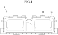
- FIGS. 1 to 3 show a conventional battery pack 1.
- the battery pack 1 includes an upper housing 10, a lower housing 20, a gasket 30 between the upper housing 10 and the lower housing 20, and a battery module 40 disposed therein.
- the present disclosure provides a gasket capable of retarding flame development to the outside of a battery pack during thermal runaway and a battery pack provided with the same.
- a gasket for retarding flame development is disposed for sealing between an upper housing and a lower housing.
- the gasket comprises: a gasket body that is disposed between the upper housing and the lower housing; and a heatproof member that is disposed on an inner side of the gasket body.
- the gasket body is formed along edges of the upper housing and the lower housing.
- the heatproof member further includes an inner coupling portion, on one side of the heatproof portion, which is coupled to the gasket body.
- the gasket body includes a groove, on the inner peripheral surface, into which the inner coupling portion is inserted.
- the inner coupling portion is formed integrally with the heatproof portion.
- the heatproof portion protrudes upward beyond an upper surface of the gasket body.
- the heatproof portion protrudes downward beyond a lower surface of the gasket body.
- an upper part of the heatproof portion is in contact with the upper housing, and a lower part of the heatproof portion is in contact with the lower housing.
- the upper and lower parts of the heatproof portion have curved portions bent toward the upper housing and the lower housing, respectively.
- the heatproof portion includes: an upper cover portion that covers an upper surface of the gasket body at an upper side of the heatproof portion; and a lower cover portion that covers the lower surface of the gasket body at a lower side of the heatproof portion.
- the heatproof member contains a heat-resistant material, and may contain mica.
- a battery pack capable of retarding flame development during thermal runway comprises: at least one battery module; a case including an upper housing and a lower housing coupled to the upper housing, and housing the battery module; and a gasket disposed between an upper housing and a lower housing, wherein the gasket comprises: a gasket body that is disposed between the upper housing and the lower housing; and a heatproof member that is disposed on an inner side of the gasket body.
- a battery pack capable of retarding flame development during thermal runway comprises: at least one battery module; a case including an upper housing and a lower housing coupled to the upper housing, and housing the battery module; and a gasket disposed between an upper housing and a lower housing, wherein the gasket comprises: a gasket body that is disposed between the upper housing and the lower housing; and a heatproof member surrounding the gasket body.
- the heatproof member covers all surfaces of the gasket body.
- the gasket and the battery pack according to the present disclosure may prevent damage to the gasket during thermal runaway and retard the flame development to the outside of the battery pack.
- FIG. 4 is a diagram showing a cross-section of one side of the battery pack in a first embodiment of the present disclosure
- FIG. 5 is a detailed view of part A in FIG. 4 .
- the gasket 300 is a gasket 300 disposed for sealing between an upper housing 100 and a lower housing 200.
- the gasket 300 includes a gasket body 310 disposed between the upper housing 100 and the lower housing 200; and a heatproof member 320 disposed on the inner side of the gasket body 310.
- the battery pack 1000 for retarding flame development during thermal runaway includes at least one battery module 400, a case 50 housing the battery module 400, and the gasket 300.
- the case 50 includes the upper housing 100 and the lower housing 200.
- gasket 300 according to the present disclosure will be described as an example applied to the battery pack 1000.
- the battery module 400 accommodated in the battery pack 1000 includes a plurality of battery cells (not shown), and each battery cell may be, for example, a pouch-type battery cell.
- the battery module 400 may include a plurality of battery cells stacked on top of each other, and each battery cell may be provided with an electrode lead at each of front and rear ends, with a positive lead at the front end and a negative lead at the rear end.
- the plurality of battery cells in the battery module 400 may be stacked to be electrically connected to each other.
- the battery cell is not limited to the pouch-type battery cell and may be other types of battery cells, such as a prismatic battery cell, and the plurality of battery cells may be accommodated in the case of the battery module 400.
- the case 50 is for housing a plurality of battery modules 400, and the case 50 may include an upper housing 100 and a lower housing 200, and may further include a gasket 300 provided between the upper and lower housings 100 and 200.
- the plurality of battery modules 400 may be accommodated in the lower housing 200, and the upper housing 100 is coupled to an upper side of the lower housing 200 to form an internal space for accommodating the battery modules 400 inside the case 50.
- the gasket 300 disposed between the upper housing 100 and the lower housing 200 is for sealing between the upper housing 100 and the lower housing 200, and the gasket 300 may be disposed across the entire portion where the upper and lower housings 100 and 200 are joined and may be in the form of a closed loop on a plane.
- the gasket 300 is disposed between the upper housing 100 and the lower housing 200 to seal between the upper housing 100 and the lower housing 200.
- the gasket 300 includes a gasket body 310 and a heatproof member 320 disposed on the inner side of the gasket body 310.
- the gasket body 310 is disposed between the upper housing 100 and the lower housing 200 for sealing, and may be disposed across the entire portion where the upper and lower housings 100 and 200 are connected.
- the gasket body 310 may be formed along the edges of the upper and lower housings 100 and 200.
- the gasket body 310 may have a ring shape or a closed loop shape on a plane.
- a groove 311 into which an inner coupling portion 322 of the heatproof member 320 is coupled may be formed on an inner surface (inner peripheral surface) 312a of the gasket body 310 located on the inner side of the case 50.
- the groove 311 may be formed on all or part of the inner peripheral surface of the gasket main body 310 depending on the formation of the inner coupling portion 322 (reference numeral 312d refers to an outer surface (outer peripheral surface) of the gasket main body 310).
- the gasket body 310 may be made of a rubber, a synthetic resin such as urethane, a metal, or other materials.
- the heatproof member 320 is for preventing or retarding damage to the gasket 300 (or the gasket body 310) during thermal explosion.
- the heatproof member 320 is disposed on the inner side of the gasket body 310 in the case 50, and includes the inner coupling portion 322 coupled to the gasket body 310 and a heatproof portion 321.
- the heatproof member 320 may be made of a heat-resistant material or may contain a heat-resistant material, and may be made of, e.g., mica, a composite material including mica, or other materials.
- the heatproof portion 321 is disposed on the inside of the gasket body 310 to prevent damage to the gasket body 310 during thermal runaway, and is formed along the inner peripheral surface of the gasket body 310 while contacting the inner surface 312a of the gasket body 310.
- the heatproof portion 321 may be formed along the entire inner peripheral surface of the gasket body 310 inside the case 50, and an up-down length (width) of the heatproof portion 321 may be formed to be equal to or greater than a thickness of the gasket body 310. Accordingly, the heatproof portion 321 may be formed to cover the entire thickness of the gasket body 310.
- the heatproof portion 321 may extend in the thickness direction of the gasket body 310, and, as shown in FIG. 5 , may protrude upward beyond an upper surface 312b of the gasket body 310 that is equal to or more than the thickness of the gasket body 310 and may protrude downward beyond a lower surface 312c of the gasket body 310 that is equal to or more than the thickness of the gasket body 310. Accordingly, the width of the heatproof portion 321 may be three times or more than the thickness of the gasket body 310.
- the heatproof portion 321 having the above-described configuration may be disposed on the inner side of the gasket body 310 to prevent damage to the gasket body 310 during thermal runaway.
- the material of the heatproof portion 321 may be the same as the material of the heatproof member 320 described above.
- the inner coupling portion 322 is disposed on a side surface of the heatproof portion 321 to couple the heatproof member 320 to the gasket body 310, and the inner coupling portion 322 is formed to protrude from the side surface of the heatproof portion 321 to contact the inner surface 312a (inner peripheral surface) of the gasket body 310 and be inserted and coupled to the groove 311 of the gasket body 310.
- the inner coupling portion 322 may be made of the same material as that of the heatproof portion 321 or that of the heatproof member 320 described above, and may be formed integrally with the heatproof portion 321.
- the heatproof member 320 may be manufactured, for example, by insert injection molding.
- the heatproof member 320 may be manufactured together with the gasket body 310 by insert injection molding, and thus the assembly process is omitted and the bonding strength may be improved.
- the gasket 300 having the above-described configuration is disposed between the upper housing 100 and the lower housing 200, and is coupled with the upper and lower housings 100 and 200 by a bolt 150, a washer 151, and a nut 152.
- the heatproof member 320 is disposed on the inner peripheral surface of the gasket body 310 to prevent or retard damage to the gasket body 310 during thermal runaway and to retard the flame to develop outside of the battery pack 1000.
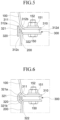
- FIG. 6 is a detailed view of the portion where the upper and lower housings 100 and 200 are joined in the second embodiment of the present disclosure.
- the difference between the second embodiment and the first embodiment is that upper and lower parts of the heatproof portion 321 of the heatproof member 320 of the gasket 300 are curved. That is, in the present embodiment, the upper and lower parts of the heatproof portion 321 may have curved portions 321a and 321b, respectively. In addition, the upper and lower parts of the heatproof portion 321 may be formed to contact the upper housing 100 and the lower housing 200, respectively.
- the curved portion 321a located at the upper side of the heatproof portion 321 is formed to be curved toward the upper housing 100, and the curved portion 321b located at the lower side of the heatproof portion 321 is formed to curved toward the lower housing 200.
- the curved portion 321a at the upper side of the heatproof portion 321 has an arc shape so that an end of the curved portion 321a can contact the upper housing 100
- the curved portion 321b at the lower side of the heatproof portion 321 has an arc shape so that an end of the curved portion 321b can contact the lower housing 200.
- the upper and lower parts of the heatproof portion 321 are curved like a bow, which may make it possible to effectively block heat from being applied to the gasket body 310 and to retard the flame to develop outside of the battery pack 1000 during thermal runaway.
- FIG. 7 is a detailed view of the portion where the upper and lower housings 100 and 200 are joined in the third embodiment of the present disclosure.
- the difference between the third embodiment and the previous embodiments is that the upper and lower parts of the heatproof portion 321 of the heatproof member 320 of the gasket 300 are formed to cover the gasket body 310 in the case 50. That is, in this embodiment, the upper and lower parts of the heatproof portion 321 may have an upper cover portion 321c and a lower cover portion 321d, respectively.
- the upper cover portion 321c located at the upper side of the heatproof portion 321 is formed to cover the upper surface 312b of the gasket body 310 in the case 50
- the lower cover portion 321d located at the lower side of the heatproof portion 321 is formed to cover the lower surface 312c of the gasket body 310 in the case 50.
- an end of the upper cover portion 321c may extend to the upper housing 100 to contact an inner surface of the upper housing 100
- the lower cover portion 321d may extend to the lower housing 200 to contact an inner surface of the lower housing 200.
- the upper and lower parts of the heatproof portion 321 have the upper cover portion 321c and the lower cover portion 321d, respectively, and may effectively block heat and/or flame from being applied to the gasket body 310 during thermal runaway.
- the inner coupling portion 322 is shown inside the heatproof portion 321, but the heatproof portion 321 may be formed without the inner coupling portion 322.
- the heatproof portion 321 may be fixed to gasket body 310 using adhesive or may be manufactured integrally together.
- FIG. 8 is a detailed view of the portion where the upper and lower housings 100 and 200 are joined in the fourth embodiment of the present disclosure.
- the heatproof member 320 of the gasket 300 is formed to cover the entire surface of the gasket body 310. That is, in the present embodiment, the heatproof member 320 is formed to surround the entire gasket body 310.
- the heatproof member 320 may be formed to surround all of the inner surface 312a of the gasket main body 310 located inside the case 50, the upper surface 312b of the gasket main body 310, the lower surface 312c of the gasket body 310, and the outer surface 312d of the gasket body 310 located outside the case 50.
- the heatproof member 320 is formed to surround the entire gasket body 310, and may effectively block heat and/or flame from being applied to the gasket body 310 during thermal runaway.
- the heatproof member 320 may be formed without the inner coupling portion 322 described above.
- the present disclosure may provide a gasket and a battery pack capable of preventing damage to the gasket and retard flame to develop outside of the battery pack during thermal runaway.
Landscapes
- Chemical & Material Sciences (AREA)
- Chemical Kinetics & Catalysis (AREA)
- Electrochemistry (AREA)
- General Chemical & Material Sciences (AREA)
- Engineering & Computer Science (AREA)
- General Engineering & Computer Science (AREA)
- Mechanical Engineering (AREA)
- Manufacturing & Machinery (AREA)
- Battery Mounting, Suspending (AREA)
- Secondary Cells (AREA)
Abstract
Description
- The present disclosure relates to a gasket and a battery pack provided with the same, and more particularly, to a gasket capable of retarding an external flame development during thermal runaway and a battery pack provided with the same.
- Unlike primary batteries which cannot be recharged, secondary batteries refer to batteries that can be charged and discharged, and are used not only in portable devices but also in electric vehicles (EVs) and hybrid electric vehicles (HEVs) that are driven by an electrical drive source.
- Types of secondary batteries currently widely used include lithium ion batteries, lithium polymer batteries, nickel cadmium batteries, nickel hydrogen batteries, and nickel zinc batteries. The operating voltage of a unit secondary battery cell, that is, a unit battery cell, is approximately 2.5V to 4.6V. Therefore, when a higher output voltage is required, a battery pack is formed by connecting multiple battery cells in series. In addition, a battery pack may also be formed by connecting multiple battery cells in parallel depending on the charge/discharge capacity required for the battery pack. Accordingly, the number of battery cells included in the battery pack may be set in various ways depending on the required output voltage or charge/discharge capacity.
- When forming a battery pack by connecting a plurality of battery cells in series/parallel, it is common to first configure a battery module comprising at least one battery cell, preferably a plurality of battery cells, and to form the battery pack by using at least one such battery module and adding other components. In this case, the battery module refers to a component in which multiple battery cells are connected in series or parallel, and the battery pack refers to a component in which multiple battery modules are connected in series or parallel to increase capacity and output.
- Typically, a vehicle battery pack has a plurality of battery modules or battery module assemblies arranged on the same plane to maintain structural stability.
-
FIGS. 1 to 3 show aconventional battery pack 1. As shown, thebattery pack 1 includes anupper housing 10, alower housing 20, agasket 30 between theupper housing 10 and thelower housing 20, and abattery module 40 disposed therein. - However, in such a
battery pack 1, in the event of an overcharge or the like, high energy may flow instantaneously, and the chemical activation of the anode material is greatly increased due to the overcharge or short circuit, so the anode material may rapidly react with the electrolyte to generate a large amount of gas and thermal runaway. During such thermal runaway, themain gasket 30 may be damaged due to flame or short circuit, which may cause flame to escape from thebattery pack 1. - The background description provided herein is for the purpose of generally presenting context of the disclosure. Unless otherwise indicated herein, the materials described in this section are not prior art to the claims in this application and are not admitted to be prior art, or suggestions of the prior art, by inclusion in this section.
- In order to solve the above problems, the present disclosure provides a gasket capable of retarding flame development to the outside of a battery pack during thermal runaway and a battery pack provided with the same.
- A gasket for retarding flame development, in accordance with one embodiment of the present disclosure, is disposed for sealing between an upper housing and a lower housing. The gasket comprises: a gasket body that is disposed between the upper housing and the lower housing; and a heatproof member that is disposed on an inner side of the gasket body.
- Further, the gasket body is formed along edges of the upper housing and the lower housing.
- Further, the heatproof member includes a heatproof portion disposed on an inner peripheral surface of the gasket body.
- Further, the heatproof member further includes an inner coupling portion, on one side of the heatproof portion, which is coupled to the gasket body.
- Further, the gasket body includes a groove, on the inner peripheral surface, into which the inner coupling portion is inserted.
- Further, the inner coupling portion is formed integrally with the heatproof portion.
- Further, the heatproof portion protrudes upward beyond an upper surface of the gasket body.
- Further, the heatproof portion protrudes downward beyond a lower surface of the gasket body.
- Further, an upper part of the heatproof portion is in contact with the upper housing, and a lower part of the heatproof portion is in contact with the lower housing.
- Further, the upper and lower parts of the heatproof portion have curved portions bent toward the upper housing and the lower housing, respectively.
- Further, the heatproof portion includes: an upper cover portion that covers an upper surface of the gasket body at an upper side of the heatproof portion; and a lower cover portion that covers the lower surface of the gasket body at a lower side of the heatproof portion.
- Further, the heatproof member contains a heat-resistant material, and may contain mica.
- A battery pack capable of retarding flame development during thermal runway, in accordance with one embodiment of the present disclosure, comprises: at least one battery module; a case including an upper housing and a lower housing coupled to the upper housing, and housing the battery module; and a gasket disposed between an upper housing and a lower housing, wherein the gasket comprises: a gasket body that is disposed between the upper housing and the lower housing; and a heatproof member that is disposed on an inner side of the gasket body.
- A battery pack capable of retarding flame development during thermal runway, in accordance with another embodiment of the present disclosure, comprises: at least one battery module; a case including an upper housing and a lower housing coupled to the upper housing, and housing the battery module; and a gasket disposed between an upper housing and a lower housing, wherein the gasket comprises: a gasket body that is disposed between the upper housing and the lower housing; and a heatproof member surrounding the gasket body.
- Further, the heatproof member covers all surfaces of the gasket body.
- The gasket and the battery pack according to the present disclosure may prevent damage to the gasket during thermal runaway and retard the flame development to the outside of the battery pack.
-
-
FIG. 1 is a diagram showing a conventional battery pack. -
FIG. 2 is a diagram showing a cross-section of one side of the battery pack inFIG. 1 . -
FIG. 3 is a detailed view of a joined portion of an upper housing and a lower housing inFIG. 2 . -
FIG. 4 is a diagram showing a cross-section of one side of a battery pack in a first embodiment of the present disclosure. -
FIG. 5 is a detailed view of part A inFIG. 4 . -
FIG. 6 is a partial detailed view of a battery pack in a second embodiment of the present disclosure. -
FIG. 7 is a partial detailed view of a battery pack in a third embodiment of the present disclosure. -
FIG. 8 is a partial detailed view of a battery pack in a fourth embodiment of the present disclosure. - The advantages and features of the present disclosure and methods for achieving them will become apparent by referring to the embodiments described in detail below along with the accompanying drawings. However, the present disclosure is not limited to the embodiments disclosed below and can be implemented in various different forms. The present embodiments are provided merely to make the disclosure of the present disclosure complete and to fully inform a person of ordinary skill in the art to which the present disclosure pertains of the scope of the present disclosure, and the present disclosure may be defined by the scope of the claims. It should be noted that, in some embodiments, well-known process steps, well-known device structures, and well-known techniques may not be specifically described to avoid ambiguous interpretation of the present disclosure. Like reference numerals may refer to like components throughout the specification.
- In the drawings, in order to clearly represent multiple layers and areas, the thickness thereof may be shown to scale. Throughout the specification, like parts may be given the same reference numerals. When it is described that a part such as a layer, membrane, region, plate, etc., is "on" another part, this includes not only a case where the part is "directly on" the another part, but also a case where there is other part between them. Conversely, when it is described that a part is "directly on" another part, it means that there is no other part between them. In addition, when it is described that a part such as a layer, membrane, region, plate, etc., is "under" another part, this includes not only a case where the part is "directly under" the another part, but also a case where there is other part between them. Conversely, when it is described that a part is "directly under" another part, it means that there is no other part between them.
- Hereinafter, a
gasket 300 for retarding flame development during thermal runaway and abattery pack 1000 provided with the same, according to a preferred embodiment of the present disclosure, will be described in detail with reference to the accompanying drawings. -
FIG. 4 is a diagram showing a cross-section of one side of the battery pack in a first embodiment of the present disclosure, andFIG. 5 is a detailed view of part A inFIG. 4 . - The
gasket 300 according to the first embodiment of the present disclosure is agasket 300 disposed for sealing between anupper housing 100 and alower housing 200. Thegasket 300 includes agasket body 310 disposed between theupper housing 100 and thelower housing 200; and aheatproof member 320 disposed on the inner side of thegasket body 310. - In addition, the
battery pack 1000 for retarding flame development during thermal runaway according to the first embodiment of the present disclosure includes at least onebattery module 400, acase 50 housing thebattery module 400, and thegasket 300. Thecase 50 includes theupper housing 100 and thelower housing 200. - Hereinafter, the
gasket 300 according to the present disclosure will be described as an example applied to thebattery pack 1000. - The
battery module 400 accommodated in thebattery pack 1000 includes a plurality of battery cells (not shown), and each battery cell may be, for example, a pouch-type battery cell. - As an example, the
battery module 400 may include a plurality of battery cells stacked on top of each other, and each battery cell may be provided with an electrode lead at each of front and rear ends, with a positive lead at the front end and a negative lead at the rear end. The plurality of battery cells in thebattery module 400 may be stacked to be electrically connected to each other. - The battery cell is not limited to the pouch-type battery cell and may be other types of battery cells, such as a prismatic battery cell, and the plurality of battery cells may be accommodated in the case of the
battery module 400. - The
case 50 is for housing a plurality ofbattery modules 400, and thecase 50 may include anupper housing 100 and alower housing 200, and may further include agasket 300 provided between the upper andlower housings - The plurality of
battery modules 400 may be accommodated in thelower housing 200, and theupper housing 100 is coupled to an upper side of thelower housing 200 to form an internal space for accommodating thebattery modules 400 inside thecase 50. - The
gasket 300 disposed between theupper housing 100 and thelower housing 200 is for sealing between theupper housing 100 and thelower housing 200, and thegasket 300 may be disposed across the entire portion where the upper andlower housings - The
gasket 300 is disposed between theupper housing 100 and thelower housing 200 to seal between theupper housing 100 and thelower housing 200. In the present disclosure, thegasket 300 includes agasket body 310 and aheatproof member 320 disposed on the inner side of thegasket body 310. - The
gasket body 310 is disposed between theupper housing 100 and thelower housing 200 for sealing, and may be disposed across the entire portion where the upper andlower housings - Accordingly, the
gasket body 310 may be formed along the edges of the upper andlower housings lower housings case 50, thegasket body 310 may have a ring shape or a closed loop shape on a plane. - A
groove 311 into which aninner coupling portion 322 of theheatproof member 320 is coupled may be formed on an inner surface (inner peripheral surface) 312a of thegasket body 310 located on the inner side of thecase 50. Thegroove 311 may be formed on all or part of the inner peripheral surface of the gasketmain body 310 depending on the formation of the inner coupling portion 322 (reference numeral 312d refers to an outer surface (outer peripheral surface) of the gasket main body 310). - The
gasket body 310 may be made of a rubber, a synthetic resin such as urethane, a metal, or other materials. - The
heatproof member 320 is for preventing or retarding damage to the gasket 300 (or the gasket body 310) during thermal explosion. Theheatproof member 320 is disposed on the inner side of thegasket body 310 in thecase 50, and includes theinner coupling portion 322 coupled to thegasket body 310 and aheatproof portion 321. Theheatproof member 320 may be made of a heat-resistant material or may contain a heat-resistant material, and may be made of, e.g., mica, a composite material including mica, or other materials. - The
heatproof portion 321 is disposed on the inside of thegasket body 310 to prevent damage to thegasket body 310 during thermal runaway, and is formed along the inner peripheral surface of thegasket body 310 while contacting theinner surface 312a of thegasket body 310. - The
heatproof portion 321 may be formed along the entire inner peripheral surface of thegasket body 310 inside thecase 50, and an up-down length (width) of theheatproof portion 321 may be formed to be equal to or greater than a thickness of thegasket body 310. Accordingly, theheatproof portion 321 may be formed to cover the entire thickness of thegasket body 310. - The
heatproof portion 321 may extend in the thickness direction of thegasket body 310, and, as shown inFIG. 5 , may protrude upward beyond anupper surface 312b of thegasket body 310 that is equal to or more than the thickness of thegasket body 310 and may protrude downward beyond alower surface 312c of thegasket body 310 that is equal to or more than the thickness of thegasket body 310. Accordingly, the width of theheatproof portion 321 may be three times or more than the thickness of thegasket body 310. - The
heatproof portion 321 having the above-described configuration may be disposed on the inner side of thegasket body 310 to prevent damage to thegasket body 310 during thermal runaway. - The material of the
heatproof portion 321 may be the same as the material of theheatproof member 320 described above. - The
inner coupling portion 322 is disposed on a side surface of theheatproof portion 321 to couple theheatproof member 320 to thegasket body 310, and theinner coupling portion 322 is formed to protrude from the side surface of theheatproof portion 321 to contact theinner surface 312a (inner peripheral surface) of thegasket body 310 and be inserted and coupled to thegroove 311 of thegasket body 310. - The
inner coupling portion 322 may be made of the same material as that of theheatproof portion 321 or that of theheatproof member 320 described above, and may be formed integrally with theheatproof portion 321. - The
heatproof member 320 may be manufactured, for example, by insert injection molding. In one example, theheatproof member 320 may be manufactured together with thegasket body 310 by insert injection molding, and thus the assembly process is omitted and the bonding strength may be improved. - The
gasket 300 having the above-described configuration is disposed between theupper housing 100 and thelower housing 200, and is coupled with the upper andlower housings bolt 150, awasher 151, and anut 152. - In the present disclosure, as described above, the
heatproof member 320 is disposed on the inner peripheral surface of thegasket body 310 to prevent or retard damage to thegasket body 310 during thermal runaway and to retard the flame to develop outside of thebattery pack 1000. - Next, a
gasket 300 for retarding flame development during thermal runaway and abattery pack 1000 provided with the same, according to a second embodiment of the present disclosure, will be described.FIG. 6 is a detailed view of the portion where the upper andlower housings - The difference between the second embodiment and the first embodiment is that upper and lower parts of the
heatproof portion 321 of theheatproof member 320 of thegasket 300 are curved. That is, in the present embodiment, the upper and lower parts of theheatproof portion 321 may havecurved portions heatproof portion 321 may be formed to contact theupper housing 100 and thelower housing 200, respectively. - As shown in
FIG. 6 , in the present embodiment, thecurved portion 321a located at the upper side of theheatproof portion 321 is formed to be curved toward theupper housing 100, and thecurved portion 321b located at the lower side of theheatproof portion 321 is formed to curved toward thelower housing 200. - The
curved portion 321a at the upper side of theheatproof portion 321 has an arc shape so that an end of thecurved portion 321a can contact theupper housing 100, and thecurved portion 321b at the lower side of theheatproof portion 321 has an arc shape so that an end of thecurved portion 321b can contact thelower housing 200. - In the second embodiment, as described above, the upper and lower parts of the
heatproof portion 321 are curved like a bow, which may make it possible to effectively block heat from being applied to thegasket body 310 and to retard the flame to develop outside of thebattery pack 1000 during thermal runaway. - The other configurations and effects may be the same as those of the first embodiment, and detailed description thereof will be omitted herein.
- Next, a
gasket 300 for retarding flame development during thermal runaway and abattery pack 1000 provided with the same, according to a third embodiment of the present disclosure, will be described.FIG. 7 is a detailed view of the portion where the upper andlower housings - The difference between the third embodiment and the previous embodiments is that the upper and lower parts of the
heatproof portion 321 of theheatproof member 320 of thegasket 300 are formed to cover thegasket body 310 in thecase 50. That is, in this embodiment, the upper and lower parts of theheatproof portion 321 may have anupper cover portion 321c and alower cover portion 321d, respectively. - As shown in
FIG. 7 , in the present embodiment, theupper cover portion 321c located at the upper side of theheatproof portion 321 is formed to cover theupper surface 312b of thegasket body 310 in thecase 50, and thelower cover portion 321d located at the lower side of theheatproof portion 321 is formed to cover thelower surface 312c of thegasket body 310 in thecase 50. Further, an end of theupper cover portion 321c may extend to theupper housing 100 to contact an inner surface of theupper housing 100, and thelower cover portion 321d may extend to thelower housing 200 to contact an inner surface of thelower housing 200. - In the third embodiment, as described above, the upper and lower parts of the
heatproof portion 321 have theupper cover portion 321c and thelower cover portion 321d, respectively, and may effectively block heat and/or flame from being applied to thegasket body 310 during thermal runaway. - Meanwhile, in
FIG. 7 , theinner coupling portion 322 is shown inside theheatproof portion 321, but theheatproof portion 321 may be formed without theinner coupling portion 322. For example, theheatproof portion 321 may be fixed togasket body 310 using adhesive or may be manufactured integrally together. - The other configurations and effects may be the same as those of the previous embodiments, and detailed description thereof will be omitted herein.
- Next, a
gasket 300 for retarding flame development during thermal runaway and abattery pack 1000 provided with the same, according to the fourth embodiment of the present disclosure, will be described.FIG. 8 is a detailed view of the portion where the upper andlower housings - The difference between the fourth embodiment and the previous embodiments is that the
heatproof member 320 of thegasket 300 is formed to cover the entire surface of thegasket body 310. That is, in the present embodiment, theheatproof member 320 is formed to surround theentire gasket body 310. - As shown in
FIG. 8 , in the present embodiment, theheatproof member 320 may be formed to surround all of theinner surface 312a of the gasketmain body 310 located inside thecase 50, theupper surface 312b of the gasketmain body 310, thelower surface 312c of thegasket body 310, and theouter surface 312d of thegasket body 310 located outside thecase 50. - In the fourth embodiment, as described above, the
heatproof member 320 is formed to surround theentire gasket body 310, and may effectively block heat and/or flame from being applied to thegasket body 310 during thermal runaway. - In the present embodiment, the
heatproof member 320 may be formed without theinner coupling portion 322 described above. - The other configurations and effects may be the same as those of the previous embodiments, and detailed description thereof will be omitted herein.
- Although the present disclosure has been described with reference to the preferred embodiments as described above, the present disclosure is not limited to the above-described embodiments and various changes and modifications may be made by those skilled in the art to which the present disclosure pertains without departing from the idea of the present disclosure.
- (Industrial Applicability)
- The present disclosure may provide a gasket and a battery pack capable of preventing damage to the gasket and retard flame to develop outside of the battery pack during thermal runaway.
Claims (20)
- A gasket for retarding flame development, which is configured to be disposed between an upper housing and a lower housing, the gasket comprising:a gasket body that is configured to be disposed between the upper housing and the lower housing; anda heatproof member that is disposed on an inner side of the gasket body.
- The gasket of claim 1, wherein the heatproof member includes a heatproof portion disposed on an inner peripheral surface of the gasket body.
- The gasket of claim 2, wherein the heatproof member includes an inner coupling portion, on one side of the heatproof portion, which is coupled to the gasket body.
- The gasket of claim 3, wherein the gasket body includes a groove, on the inner peripheral surface, into which the inner coupling portion is inserted.
- The gasket of claim 3, wherein the inner coupling portion is formed integrally with the heatproof portion.
- The gasket of claim 2, wherein the heatproof portion protrudes upward beyond an upper surface of the gasket body.
- The gasket of claim 2, wherein the heatproof portion protrudes downward beyond a lower surface of the gasket body.
- The gasket of claim 2, wherein an upper part of the heatproof portion is configured to contact with the upper housing, and
a lower part of the heatproof portion is configured to contact with the lower housing. - The gasket of claim 2, wherein upper and lower parts of the heatproof portion have curved portions, which are configured to be bent toward the upper housing and the lower housing, respectively.
- The gasket of claim 2, wherein the heatproof portion includes:an upper cover portion that covers an upper surface of the gasket body at an upper side of the heatproof portion; anda lower cover portion that covers the lower surface of the gasket body at a lower side of the heatproof portion.
- The gasket of claim 2, wherein the heatproof member contains a heat-resistant material.
- A gasket for retarding flame development, which is configured to be disposed between an upper housing and a lower housing, the gasket comprising:a gasket body that is configured to be disposed between the upper housing and the lower housing; anda heatproof member surrounding the gasket body.
- The gasket of claim 12, wherein the heatproof member covers all surfaces of the gasket body.
- A battery pack capable of retarding flame development during thermal runway, comprising:at least one battery module;a case including an upper housing and a lower housing coupled to the upper housing, and housing the battery module; anda gasket disposed between an upper housing and a lower housing,wherein the gasket comprises:a gasket body that is disposed between the upper housing and the lower housing; anda heatproof member that is disposed on an inner side of the gasket body.
- The battery pack of claim 14, wherein the heatproof member includes a heatproof portion disposed on an inner peripheral surface of the gasket body.
- The battery pack of claim 15, wherein the heatproof member includes an inner coupling portion, on one side of the heatproof portion, which is coupled to the gasket body.
- The battery pack of claim 16, wherein the gasket body includes a groove, on the inner peripheral surface, into which the inner coupling portion is inserted.
- The battery pack of claim 15, wherein the heatproof portion protrudes upward beyond an upper surface of the gasket body and protrudes downward beyond a lower surface of the gasket body.
- A battery pack capable of retarding flame development during thermal runway, comprising:at least one battery module;a case including an upper housing and a lower housing coupled to the upper housing, and housing the battery module;a gasket disposed between an upper housing and a lower housing,wherein the gasket comprises:a gasket body that is disposed between the upper housing and the lower housing; anda heatproof member surrounding the gasket body.
- The battery pack of claim 19, wherein the heatproof member covers all surfaces of the gasket body.
Applications Claiming Priority (2)
| Application Number | Priority Date | Filing Date | Title |
|---|---|---|---|
| KR1020230040474A KR20240145700A (en) | 2023-03-28 | 2023-03-28 | Gasket for delaying flame release in case of thermal propagation and battery pack having the same |
| PCT/KR2023/021525 WO2024204960A1 (en) | 2023-03-28 | 2023-12-26 | Gasket for delaying flame outbreak during thermal runaway and battery pack equipped with same |
Publications (3)
| Publication Number | Publication Date |
|---|---|
| EP4492551A1 true EP4492551A1 (en) | 2025-01-15 |
| EP4492551A4 EP4492551A4 (en) | 2025-10-01 |
| EP4492551B1 EP4492551B1 (en) | 2026-04-22 |
Family
ID=92906978
Family Applications (1)
| Application Number | Title | Priority Date | Filing Date |
|---|---|---|---|
| EP23931068.3A Active EP4492551B1 (en) | 2023-03-28 | 2023-12-26 | Gasket for retarding flame development during thermal runaway and battery pack provided with same |
Country Status (5)
| Country | Link |
|---|---|
| EP (1) | EP4492551B1 (en) |
| JP (1) | JP2025513991A (en) |
| KR (1) | KR20240145700A (en) |
| CN (1) | CN119156734A (en) |
| WO (1) | WO2024204960A1 (en) |
Family Cites Families (9)
| Publication number | Priority date | Publication date | Assignee | Title |
|---|---|---|---|---|
| GB2537384B (en) * | 2015-04-14 | 2018-01-03 | Taylor Kerr (Couplings) Ltd | Fire resistant pipe coupling |
| CN209880682U (en) * | 2019-04-10 | 2019-12-31 | 郑州深澜动力科技有限公司 | Battery box and power battery using same |
| KR102922131B1 (en) * | 2020-04-29 | 2026-02-02 | 주식회사 엘지에너지솔루션 | Battery pack and device including the same |
| CN211980723U (en) * | 2020-05-29 | 2020-11-20 | 比亚迪股份有限公司 | battery pack and vehicle |
| CN213026312U (en) * | 2020-07-23 | 2021-04-20 | 北京新能源汽车股份有限公司 | Battery box for vehicle and vehicle |
| CN213042997U (en) * | 2020-08-12 | 2021-04-23 | 恒大新能源技术(深圳)有限公司 | Battery pack case, battery pack and vehicle |
| CN213752872U (en) * | 2020-12-29 | 2021-07-20 | 长城汽车股份有限公司 | Battery case and battery pack having the same |
| KR102824055B1 (en) * | 2021-01-08 | 2025-06-20 | 주식회사 엘지에너지솔루션 | Battery Pack, Energy Storage System, and Vehicle |
| CN215496950U (en) * | 2021-08-09 | 2022-01-11 | 长城汽车股份有限公司 | Battery pack and vehicle having the same |
-
2023
- 2023-03-28 KR KR1020230040474A patent/KR20240145700A/en active Pending
- 2023-12-26 JP JP2024549546A patent/JP2025513991A/en active Pending
- 2023-12-26 CN CN202380038781.0A patent/CN119156734A/en active Pending
- 2023-12-26 EP EP23931068.3A patent/EP4492551B1/en active Active
- 2023-12-26 WO PCT/KR2023/021525 patent/WO2024204960A1/en not_active Ceased
Also Published As
| Publication number | Publication date |
|---|---|
| EP4492551B1 (en) | 2026-04-22 |
| EP4492551A4 (en) | 2025-10-01 |
| JP2025513991A (en) | 2025-05-02 |
| KR20240145700A (en) | 2024-10-07 |
| CN119156734A (en) | 2024-12-17 |
| WO2024204960A1 (en) | 2024-10-03 |
Similar Documents
| Publication | Publication Date | Title |
|---|---|---|
| KR101623110B1 (en) | Electrode lead and secondary battery including the same | |
| US7718306B2 (en) | Rechargeable battery with gas release safety vent | |
| US8043743B2 (en) | Pouch type secondary battery with improved safety | |
| KR102897974B1 (en) | Battery cell and its manufacturing method, manufacturing system, battery and electrical device | |
| US20240234930A9 (en) | Battery module and battery pack including the same | |
| KR20180036086A (en) | Cylindrical Battery Cell Comprising Metal Can Having Groove | |
| KR101766047B1 (en) | Battery Cell | |
| KR20140087773A (en) | Pouch type secondary battery with enhanced stability | |
| US20240030531A1 (en) | Battery module and battery pack including the same | |
| KR20130118232A (en) | Rechargeable battery | |
| KR102117076B1 (en) | Battery Module Assembly | |
| KR20220092100A (en) | Secondary battery and manufacturing method of the same | |
| EP4181275A1 (en) | Battery module and battery pack including same | |
| US12381288B2 (en) | Busbar module and method of manufacturing the same | |
| KR102379765B1 (en) | The Secondary Battery And The Battery Module | |
| US8481193B2 (en) | Battery module and method of manufacturing the same | |
| US20250062495A1 (en) | Battery cell, battery, and electric device | |
| EP4492551B1 (en) | Gasket for retarding flame development during thermal runaway and battery pack provided with same | |
| EP4432446A1 (en) | Battery module and, battery pack comprising same and vehicle comprising same | |
| US20250253480A1 (en) | Battery pack for relieving internal pressure during thermal runaway | |
| KR20230160044A (en) | Battery cell and manufacturing method thereof | |
| KR20210117044A (en) | The Secondary Battery And The Battery Module | |
| KR100449755B1 (en) | Secondary battery | |
| EP4621977A1 (en) | Battery module and battery pack comprising same | |
| KR20150066159A (en) | Can assay of litium ion battery with high capacity and power |
Legal Events
| Date | Code | Title | Description |
|---|---|---|---|
| STAA | Information on the status of an ep patent application or granted ep patent |
Free format text: STATUS: THE INTERNATIONAL PUBLICATION HAS BEEN MADE |
|
| PUAI | Public reference made under article 153(3) epc to a published international application that has entered the european phase |
Free format text: ORIGINAL CODE: 0009012 |
|
| STAA | Information on the status of an ep patent application or granted ep patent |
Free format text: STATUS: REQUEST FOR EXAMINATION WAS MADE |
|
| 17P | Request for examination filed |
Effective date: 20241011 |
|
| AK | Designated contracting states |
Kind code of ref document: A1 Designated state(s): AL AT BE BG CH CY CZ DE DK EE ES FI FR GB GR HR HU IE IS IT LI LT LU LV MC ME MK MT NL NO PL PT RO RS SE SI SK SM TR |
|
| A4 | Supplementary search report drawn up and despatched |
Effective date: 20250829 |
|
| RIC1 | Information provided on ipc code assigned before grant |
Ipc: H01M 50/24 20210101AFI20250825BHEP Ipc: H01M 10/613 20140101ALI20250825BHEP Ipc: H01M 50/105 20210101ALI20250825BHEP Ipc: H01M 50/233 20210101ALI20250825BHEP Ipc: H01M 50/204 20210101ALI20250825BHEP Ipc: F16J 15/06 20060101ALI20250825BHEP |
|
| GRAP | Despatch of communication of intention to grant a patent |
Free format text: ORIGINAL CODE: EPIDOSNIGR1 |
|
| STAA | Information on the status of an ep patent application or granted ep patent |
Free format text: STATUS: GRANT OF PATENT IS INTENDED |
|
| RIC1 | Information provided on ipc code assigned before grant |
Ipc: H01M 50/24 20210101AFI20260114BHEP Ipc: H01M 10/613 20140101ALI20260114BHEP Ipc: H01M 50/105 20210101ALI20260114BHEP Ipc: H01M 50/233 20210101ALI20260114BHEP Ipc: H01M 50/204 20210101ALI20260114BHEP Ipc: F16J 15/06 20060101ALI20260114BHEP |
|
| DAV | Request for validation of the european patent (deleted) | ||
| DAX | Request for extension of the european patent (deleted) | ||
| INTG | Intention to grant announced |
Effective date: 20260126 |
|
| P01 | Opt-out of the competence of the unified patent court (upc) registered |
Free format text: CASE NUMBER: UPC_APP_0003975_4492551/2026 Effective date: 20260203 |
|
| GRAS | Grant fee paid |
Free format text: ORIGINAL CODE: EPIDOSNIGR3 |
|
| GRAA | (expected) grant |
Free format text: ORIGINAL CODE: 0009210 |
|
| STAA | Information on the status of an ep patent application or granted ep patent |
Free format text: STATUS: THE PATENT HAS BEEN GRANTED |
|
| AK | Designated contracting states |
Kind code of ref document: B1 Designated state(s): AL AT BE BG CH CY CZ DE DK EE ES FI FR GB GR HR HU IE IS IT LI LT LU LV MC ME MK MT NL NO PL PT RO RS SE SI SK SM TR |
|
| REG | Reference to a national code |
Ref country code: CH Ref legal event code: F10 Free format text: ST27 STATUS EVENT CODE: U-0-0-F10-F00 (AS PROVIDED BY THE NATIONAL OFFICE) Effective date: 20260422 Ref country code: GB Ref legal event code: FG4D |
|
| REG | Reference to a national code |
Ref country code: DE Ref legal event code: R096 Ref document number: 602023015904 Country of ref document: DE |