EP4492537A1 - Energy storage rack and energy storage container - Google Patents
Energy storage rack and energy storage container Download PDFInfo
- Publication number
- EP4492537A1 EP4492537A1 EP23216107.5A EP23216107A EP4492537A1 EP 4492537 A1 EP4492537 A1 EP 4492537A1 EP 23216107 A EP23216107 A EP 23216107A EP 4492537 A1 EP4492537 A1 EP 4492537A1
- Authority
- EP
- European Patent Office
- Prior art keywords
- vertical beam
- energy storage
- battery pack
- inlet
- outlet
- Prior art date
- Legal status (The legal status is an assumption and is not a legal conclusion. Google has not performed a legal analysis and makes no representation as to the accuracy of the status listed.)
- Granted
Links
Images






Classifications
-
- H—ELECTRICITY
- H01—ELECTRIC ELEMENTS
- H01M—PROCESSES OR MEANS, e.g. BATTERIES, FOR THE DIRECT CONVERSION OF CHEMICAL ENERGY INTO ELECTRICAL ENERGY
- H01M10/00—Secondary cells; Manufacture thereof
- H01M10/60—Heating or cooling; Temperature control
- H01M10/61—Types of temperature control
- H01M10/613—Cooling or keeping cold
-
- H—ELECTRICITY
- H01—ELECTRIC ELEMENTS
- H01M—PROCESSES OR MEANS, e.g. BATTERIES, FOR THE DIRECT CONVERSION OF CHEMICAL ENERGY INTO ELECTRICAL ENERGY
- H01M50/00—Constructional details or processes of manufacture of the non-active parts of electrochemical cells other than fuel cells, e.g. hybrid cells
- H01M50/20—Mountings; Secondary casings or frames; Racks, modules or packs; Suspension devices; Shock absorbers; Transport or carrying devices; Holders
- H01M50/204—Racks, modules or packs for multiple batteries or multiple cells
- H01M50/207—Racks, modules or packs for multiple batteries or multiple cells characterised by their shape
-
- H—ELECTRICITY
- H01—ELECTRIC ELEMENTS
- H01M—PROCESSES OR MEANS, e.g. BATTERIES, FOR THE DIRECT CONVERSION OF CHEMICAL ENERGY INTO ELECTRICAL ENERGY
- H01M10/00—Secondary cells; Manufacture thereof
- H01M10/60—Heating or cooling; Temperature control
- H01M10/65—Means for temperature control structurally associated with the cells
- H01M10/655—Solid structures for heat exchange or heat conduction
- H01M10/6556—Solid parts with flow channel passages or pipes for heat exchange
-
- H—ELECTRICITY
- H01—ELECTRIC ELEMENTS
- H01M—PROCESSES OR MEANS, e.g. BATTERIES, FOR THE DIRECT CONVERSION OF CHEMICAL ENERGY INTO ELECTRICAL ENERGY
- H01M10/00—Secondary cells; Manufacture thereof
- H01M10/60—Heating or cooling; Temperature control
- H01M10/65—Means for temperature control structurally associated with the cells
- H01M10/656—Means for temperature control structurally associated with the cells characterised by the type of heat-exchange fluid
- H01M10/6567—Liquids
- H01M10/6568—Liquids characterised by flow circuits, e.g. loops, located externally to the cells or cell casings
-
- Y—GENERAL TAGGING OF NEW TECHNOLOGICAL DEVELOPMENTS; GENERAL TAGGING OF CROSS-SECTIONAL TECHNOLOGIES SPANNING OVER SEVERAL SECTIONS OF THE IPC; TECHNICAL SUBJECTS COVERED BY FORMER USPC CROSS-REFERENCE ART COLLECTIONS [XRACs] AND DIGESTS
- Y02—TECHNOLOGIES OR APPLICATIONS FOR MITIGATION OR ADAPTATION AGAINST CLIMATE CHANGE
- Y02E—REDUCTION OF GREENHOUSE GAS [GHG] EMISSIONS, RELATED TO ENERGY GENERATION, TRANSMISSION OR DISTRIBUTION
- Y02E60/00—Enabling technologies; Technologies with a potential or indirect contribution to GHG emissions mitigation
- Y02E60/10—Energy storage using batteries
Definitions
- the disclosure belongs to the technical field of energy storage equipment, and in particular, relates to an energy storage rack and an energy storage container.
- an energy storage container includes a container body and energy storage racks integrated in the container body, and battery packs for storing electrical energy are provided in the energy storage racks.
- the battery packs have higher temperature requirements when working. When the temperature of one battery pack exceeds its normal operating temperature due to factors such as the ambient temperature or the heat generated by the battery pack itself during charging and discharging, the battery pack needs to be heat exchanged to maintain the stable operation of the energy storage container and extend the service life of the battery pack.
- the energy storage racks are generally equipped with heat exchange pipelines for transporting heat exchange medium.
- the heat exchange medium enters each battery pack through the heat exchange pipeline to exchange heat for the battery pack. After heat exchange, the heat exchange medium flows out through the heat exchange pipeline to form a heat exchange cycle. Due to the large number of battery packs in the energy storage racks, the heat exchange pipeline structure is complex and occupies a large space. The energy density of energy storage racks and energy storage container is thus reduced, which is not conducive to the lightweight and miniaturization of the energy storage racks and the energy storage container. Further, due to the large number of battery packs, the battery packs block and obstruct one another, making the connection and maintenance between the heat exchange pipelines and the battery packs difficult.
- the disclosure aims to provide an energy storage rack and an energy storage container to solve the problems in the related art that the structure of the heat exchange pipelines is complex and occupies a large space, and the connection and maintenance between the heat exchange pipelines and battery packs are difficult.
- an energy storage rack including a frame.
- the frame is provided with a plurality of layers of accommodation spaces stacked in a first direction.
- the frame includes four vertical beams arranged in the first direction, and the four vertical beams are a first vertical beam, a second vertical beam, a third vertical beam, and a fourth vertical beam.
- a flow channel is arranged in each of the four vertical beams.
- first vertical beam and the second vertical beam are located on one side of the accommodation spaces, and the third vertical beam and the fourth vertical beam are located on the other side of the accommodation spaces opposite to the first vertical beam and the second vertical beam.
- Two battery packs are arranged in each of the accommodation space of each layer, and the two battery packs respectively are a first battery pack and a second battery pack.
- the first battery pack is arranged close to the first vertical beam and the second vertical beam
- the second battery pack is arranged close to the third vertical beam and the fourth vertical beam.
- the first battery pack has a first inlet for a heat exchange medium to flow in and a first outlet for the heat exchange medium to flow out.
- the second battery pack has a second inlet for the heat exchange medium to flow in and a second outlet for the heat exchange medium to flow out.
- a heat exchange flow channel is provided in each of the battery packs.
- the heat exchange flow channel of the first battery pack communicates with the first inlet and the first outlet
- the heat exchange flow channel of the second battery pack communicates with the second inlet and the second outlet.
- the first inlet and the first outlet are arranged close to the first vertical beam and the second vertical beam, and the second inlet and the second outlet are arranged close to the third vertical beam and the fourth vertical beam.
- the first inlet communicates with the flow channel of the first vertical beam, and the first outlet communicates with the flow channel of the second vertical beam.
- the second inlet communicates with the flow channel of the third vertical beam, and the second outlet communicates with the flow channel of the fourth vertical beam.
- each of the battery packs includes a panel, the first inlet and the first outlet are arranged on the panel of the first battery pack, and the second inlet and the second outlet are arranged on the panel of the second battery pack.
- the panel of the first battery pack is located on a side surface of the first battery pack close to the first vertical beam and the second vertical beam.
- the panel of the second battery pack is located on a side surface of the second battery pack close to the third vertical beam and the fourth vertical beam.
- each of the battery packs includes a housing body and a battery assembly, the battery assembly is arranged in a space surrounded by the housing body and the panel, and the panel and the housing body are detachably connected.
- the panel is provided with a communication port and a charging and discharging port.
- the energy storage rack further includes a plurality of connecting pipes corresponding to the first inlet, the first outlet, the second inlet, and the second outlet.
- the first inlet communicates with the flow channel of the first vertical beam through the corresponding connecting pipe
- the first outlet communicates with the flow channel of the second vertical beam through the corresponding connecting pipe
- the second inlet communicates with the flow channel of the third vertical beam through the corresponding connecting pipe
- the second outlet communicates with the flow channel of the fourth vertical beam through the corresponding connecting pipe.
- each of the connecting pipes is a flexible hose.
- each of the first inlet, the first outlet, the second inlet, and the second outlet is provided with a quick connector.
- Each of the first inlet, the first outlet, the second inlet, and the second outlet communicates with the corresponding connecting pipe through the quick connector.
- the frame further includes connecting members, and the connecting members are connected to the four vertical beams.
- connecting members There are a plurality of connecting members, and the connecting members are sequentially arranged in the first direction and form the accommodation spaces in the frame.
- the frame further includes auxiliary supporting beams arranged in the first direction and connected to the connecting members.
- a general communicating port is provided on an end portion of each of the vertical beams corresponding to the vertical beam, and the general communicating port communicates with the flow channel in the vertical beam.
- the disclosure further provides an energy storage container including a container body and a plurality of energy storage racks arranged in the container body according to anyone of the above.
- the energy storage racks are arranged side by side in a third direction perpendicular to the first direction and the second direction.
- the first vertical beam is spaced apart from the second vertical beam in the third direction, and the first battery pack enters and exits the accommodation space through a gap between the first vertical beam and the second vertical beam.
- the third vertical beam is spaced apart from the fourth vertical beam in the third direction, and the second battery pack enters and exits the accommodation space through a gap between the third vertical beam and the fourth vertical beam.
- the two vertical beams that are close to each other between two adjacent energy storage racks are combined into an integrated vertical beam, and the two flow channels in the integrated vertical beam are separated from each other.
- container doors are provided on a side surface of the container body relative to the energy storage racks in the second direction.
- the energy storage racks are arranged side by side into two energy storage aggregates spaced apart from each other in the second direction, and a gap between the two energy storage aggregates is used for an operator to pass through.
- beneficial effects provided by the disclosure include the following. Since each of the vertical beams is provided with the flow channel and the flow channel communicates with the heat exchange flow channel of the corresponding battery pack, the heat exchange medium may enter the battery pack through the vertical beam to exchange heat with the battery pack, and the heat exchange medium after heat exchange may flow out from the vertical beam.
- the arrangement of the flow channel in each of the vertical beams replaces part of the heat exchange pipeline, so that the structure of the energy storage rack is simplified, the space occupied by the heat exchange pipelines is reduced, and the material costs and installation costs of the pipelines are lowered. It is beneficial to the miniaturization and lightweight of the energy storage rack and improves the energy density of the energy storage rack.
- the first vertical beam and the second vertical beam are located on one side of the accommodation spaces
- the third vertical beam and the fourth vertical beam are located on the other side of the accommodation spaces opposite to the first vertical beam and the second vertical beam
- the first battery pack is arranged close to the first vertical beam and the second vertical beam
- the second battery pack is arranged close to the third vertical beam and the fourth vertical beam, that is, the two battery packs are arranged close to the corresponding vertical beams. Therefore, when the first battery pack is being connected to the first vertical beam and the second vertical beam or when the first battery pack is being maintained, the connection or the maintenance may be made from the side of the frame corresponding to the first vertical beam and the second vertical beam.
- connection or the maintenance may be made from the side of the frame corresponding to the third vertical beam and the fourth vertical beam, which is simple and convenient. Further, the two battery packs are close to the corresponding vertical beams, so that the two battery packs are far away from each other, the interference between the two battery packs is reduced, and connection between the battery packs and the vertical beams and maintenance on the battery packs can be easily performed.
- this embodiment provides an energy storage rack 10 including a frame 1 provided with a plurality of layers of accommodation spaces 18 stacked in a first direction ⁇ .
- the frame 1 includes four vertical beams all arranged in the first direction ⁇ , and a flow channel 111 is arranged in each of the four vertical beams.
- the fourth vertical beams respectively are a first vertical beam 11, a second vertical beam 12, a third vertical beam 13, and a fourth vertical beam 14.
- first vertical beam 11 and the second vertical beam 12 are located on one side of the accommodation spaces 18, and the third vertical beam 13 and the fourth vertical beam 14 are located on the other side of the accommodation spaces 18 relative to the first vertical beam 11 and the second vertical beam 12.
- the second direction ⁇ is perpendicular to the first direction ⁇ .
- the two battery packs are arranged in each of the accommodation spaces, and the two battery packs are a first battery pack 31 and a second battery pack 32.
- the first battery pack 31 is arranged close to the first vertical beam 11 and the second vertical beam 12, and the second battery pack 32 is arranged close to the third vertical beam 13 and the fourth vertical beam 14.
- a heat exchange flow channel 308 is provided in each of the first battery pack 31 and the second battery pack 32.
- the first battery pack 31 has a first inlet 304 for a heat exchange medium to flow in and a first outlet 305 for the heat exchange medium to flow out, and the heat exchange flow channel 308 of the first battery pack 31 communicates with the first inlet 304 and the first outlet 305.
- the second battery pack 32 has a second inlet 306 for the heat exchange medium to flow in and a second outlet 307 for the heat exchange medium to flow out, and the heat exchange flow channel 308 of the second battery pack 32 communicates with the second inlet 306 and the second outlet 307.
- the first inlet 304 and the first outlet 305 of the first battery pack 31 are arranged close to the first vertical beam 11 and the second vertical beam 12, and the second inlet 306 and the second outlet 307 of the second battery pack 32 are arranged close to the third vertical beam 13 and the fourth vertical beam 14.
- the first inlet 304 communicates with the flow channel 111 of the first vertical beam 11, and the first outlet 305 communicates with the flow channel 111 of the second vertical beam 12.
- the second inlet 306 communicates with the flow channel 111 of the third vertical beam 13, and the second outlet 307 communicates with the flow channel 111 of the fourth vertical beam 14.
- the heat exchange flow channels 308 are used for heat exchange with inner portions of the battery packs, so that the temperature of the battery packs may be kept in a suitable temperature range, and that the energy storage efficiency, charging and discharging efficiency, and safety performance of the battery packs may be kept.
- the heat exchange flow channels 308 may be arranged in heat exchange components such as heat exchange plates, and the heat exchange components are separately arranged and assembled in the battery packs, so assembly and maintenance may be easily performed.
- heat exchange components such as heat exchange plates
- the heat exchange components are separately arranged and assembled in the battery packs, so assembly and maintenance may be easily performed.
- the presence of the heat exchange components increases the number of components and parts in the battery packs and occupies a large space, so that the assembly steps are increased and the space utilization rate within a housing body 302 is also reduced.
- the heat exchange flow channels 308 may be integrated into an inner wall of the housing body 302, such as bottom portions of the battery packs, and do not need to be separately arranged. In this way, the number of components and parts in the battery packs is reduced, the assembly steps are simplified, and the available spaces in the battery packs are increased, so that the energy density of the battery packs is increased. However, the heat exchange flow channels 308 are integrated into the inner wall of the housing body 302, so that the processing difficulty of the housing body 302 increases, and replacement and maintenance of the heat exchange flow channels 308 may not be easily performed.
- each accommodation space 18 is provided with the first battery pack 31 and the second battery pack 32.
- the specific number of battery packs in the energy storage rack 10 may be set according to the energy storage requirements of the energy storage rack 10. When two battery packs are installed in each of the accommodation spaces 18, the energy storage rack 10 has the largest energy storage capacity and the highest energy density.
- the flow channel 111 is provided in each of the vertical beams, and the flow channel 111 communicates with the heat exchange flow channel 308 of the corresponding battery pack. Therefore, the heat exchange medium may enter the battery pack through the vertical beam to exchange heat with the battery pack, and the heat exchange medium after heat exchange may also flow out from the vertical beam.
- the arrangement of the flow channel 111 in each of the vertical beams replaces part of a heat exchange pipeline, so that the structure of the energy storage rack 10 is simplified, the space occupied by the heat exchange pipelines is reduced, and the material costs and installation costs of the pipelines are lowered. It is beneficial to the miniaturization and lightweight of the energy storage rack 10 and improves the energy density of the energy storage rack 10.
- the first battery pack 31 is arranged close to the first vertical beam 11 and the second vertical beam 12 and the second battery pack 32 is arranged close to the third vertical beam 13 and the fourth vertical beam 14, that is, the two battery packs are arranged close to the corresponding vertical beams.
- the connection or the maintenance may be made from the side of the frame 1 corresponding to the first vertical beam 11 and the second vertical beam 12.
- the connection or the maintenance may be made from the side of the frame 1 corresponding to the third vertical beam 13 and the fourth vertical beam 14, which is simple and convenient.
- the two battery packs are close to the corresponding vertical beams, so that the two battery packs are far away from each other, interference between the two battery packs is reduced, and connection and maintenance may be easily performed.
- the vertical beams are made of profiles, and the flow channels 111 in the vertical beams may be directly extruded during profile extrusion without additional processing, so the overall costs are low.
- the first outlet 305 is arranged close to the first vertical beam 11, the first inlet 304 is arranged close to the second vertical beam 12, the second outlet 307 is arranged close to the third vertical beam 13, and the second inlet 306 is arranged close to the fourth vertical beam 14.
- the first outlet 305 is arranged close to the second vertical beam 12
- the first inlet 304 is arranged close to the first vertical beam 11
- the second inlet 306 is arranged close to the third vertical beam 13
- the second outlet 307 is arranged close to the fourth vertical beam 14.
- the first inlet 304, the first outlet 305, the second inlet 306, and the second outlet 307 are close to the connected vertical beams, so that connection or maintenance between the vertical beams and the corresponding battery packs may be easily performed.
- the first direction ⁇ is set in a horizontal direction, that is, the multi-layer accommodation spaces 18 are stacked in sequence in the horizontal direction.
- the first direction ⁇ is set in a vertical direction
- the second direction ⁇ is set in the horizontal direction
- the multi-layer accommodation spaces 18 are stacked in sequence in the vertical direction, so that the space in a height direction may be fully utilized, and the space utilization of the energy storage rack 10 may be improved.
- the battery packs may enter the accommodation spaces 18 in the horizontal direction, which is convenient for an operator to operate.
- each of the battery packs includes a panel 301, the first inlet 304 and the first outlet 305 of the first battery pack 31 are arranged on the panel 301 of the first battery pack 31, and the second inlet 306 and the second outlet 307 of the second battery pack 32 are arranged on the panel 301 of the second battery pack 32.
- the side where the panel 301 is located is an operating side of each of the battery pack.
- the panel 301 of the first battery pack 31 is located on a side surface of the first battery pack 31 close to the first vertical beam 11 and the second vertical beam 12, and the panel 301 of the second battery pack 32 is located on a side surface of the second battery pack 32 close to the third vertical beam 13 and the fourth vertical beam 14.
- Operations such as connecting and maintaining the panel 301 of the first battery pack 31 may be performed from the positions of the first vertical beam 11 and the second vertical beam 12, and operations such as connecting and maintaining the panel 301 of the second battery pack 32 may be performed from the positions of the third vertical beam 13 and the fourth vertical beam 14, so these operations may be easily performed.
- each of the battery packs includes a charging and discharging port 309 and a communication port 310.
- the charging and discharging port 309 and the communication port 310 are also arranged on the panel 301.
- the charging and discharging port 309 is a high-voltage port including a charging port and a discharging port.
- the charging port is used to charge the battery pack, and the discharging port is used to output electric energy from the battery pack.
- the communication port 310 is a low-voltage port, and communication information, sensor detection results, and low-voltage power supply are all output through the communication port 310.
- an explosion-proof valve 311 of the battery pack is also arranged on the panel 301. The explosion-proof valve 311 may relieve the pressure of the battery pack when the pressure in the battery pack exceeds the safety threshold, prevent the battery pack from exploding, and improve the safety performance of the battery pack.
- each of the battery packs includes the housing body 302 and a battery assembly, the panel 301 and the housing body 302 is detachably connected, and the battery assembly is arranged in an internal space surrounded by the housing body 302 and the panel 301.
- the battery assembly is used to store electric energy, and the housing body 302 and the panel 301 are used to fix, support, and protect the battery assembly.
- the panel 301 and the housing body 302 are arranged separately, and the panel 301 and the housing body 302 are detachably connected, so maintenance and replacement of the panel 301 may be easily performed.
- the housing body 302 has an installation opening through which the battery assembly may enter and exit the housing body 302, and the panel 301 is detachably connected onto the installation opening.
- the housing body 302 and the panel 301 are combined to form a complete housing body.
- the battery assembly may enter and exit the housing body 302 through the installation opening, so that the battery assembly may be easily repaired and replaced.
- the energy storage rack 10 further includes a plurality of connecting pipes 17.
- the first inlet 304 communicates with the flow channel 111 of the first vertical beam 11 through the corresponding connecting pipe 17, the first outlet 305 communicates with the flow channel 111 of the second vertical beam 12 through the corresponding connecting pipe 17, the second inlet 306 communicates with the flow channel 111 of the third vertical beam 13 through the corresponding connecting pipe 17, and the second outlet 307 communicates with the flow channel 111 of the fourth vertical beam 14 through the corresponding connecting pipe 17.
- the first inlet 304, the first outlet 305, the second inlet 306, and the second outlet 307 may be connected to the corresponding vertical beams through the corresponding connecting pipes 17, so that compared with the direct connection between the battery packs and the vertical beams, the relative position requirements between the battery packs and the vertical beams may be reduced, and the difficulty of processing and installation may be lowered. Further, the corresponding moderate increase in the distance between the battery packs and the vertical beams is conducive to increasing the operating space when the battery packs are connected to the vertical beams.
- each of the connecting pipes 17 is a flexible hose in this embodiment.
- the flexible hose may be bent and deformed according to the installation position, so that the position accuracy and processing accuracy requirements between the battery packs and the corresponding vertical beams are lowered, and the connection between the vertical beams and battery packs may be easily performed.
- each of the first inlet 304, the first outlet 305, the second inlet 306, and the second outlet 307 is provided with a quick connector.
- Each of the first inlet 304, the first outlet 305, the second inlet 306, and the second outlet 306 communicates with the corresponding connecting pipe 17 through the quick connector.
- each of the vertical beams is also provided with a quick connector communicating with the flow channel 111 in the vertical beam, and the connecting pipes 17 communicate with the flow channels 111 in the vertical beams through the quick connectors.
- each of the connecting pipes 17 may be connected to the corresponding vertical beam in advance.
- the other ends of the connecting pipes 17 are connected to the quick connectors on the battery packs, so the heat exchange flow channels 308 in the battery packs may communicate with the corresponding flow channels 111 in the vertical beams, which is convenient and fast.
- the frame further includes connecting members 16, and the connecting members 16 are connected to the four vertical beams.
- the connecting members 16 are sequentially arranged in the first direction ⁇ and form the accommodation spaces 18 in the frame.
- the connecting members 16 may be in the form of plates or shelves, and the connecting members 16 divide the space in the frame into the plurality of accommodation spaces 18.
- the connecting members 16 include two opposite supporting cross beams 19. One supporting cross beam 19 is connected to the first vertical beam 11 and the fourth vertical beam 14, and the other supporting cross beam 19 is connected to the second vertical beam 12 and the third vertical beam 13. When the battery packs are installed in the accommodation spaces 18, the supporting cross beams 19 support the battery packs.
- the frame further includes auxiliary supporting beams 15 arranged in the first direction ⁇ and connected to the connecting members 16.
- the auxiliary supporting beams 15 may increase the structural strength of the frame in the first direction ⁇ , so that the frame may carry more battery packs in the first direction ⁇ .
- the frame may also include other reinforcing beams to enhance the structural strength of the frame and avoid deformation of the frame.
- a general communicating port 102 is provided on an end portion of each of the vertical beams corresponding to the vertical beam, and the general communicating port 102 communicates with the flow channel in the vertical beam.
- the general communicating port 102 is configured to communicate with a medium input pipeline or a medium output pipeline.
- the heat exchange medium may enter the flow channel of the vertical beam through the general communicating port 102 and then enters each battery pack through the flow channel for heat exchange.
- the heat exchange medium after heat exchange flows out from each battery pack, enters the flow channel of another vertical beam, and is discharged from the general communicating port 102 of the vertical beam.
- the general communicating port 102 is provided corresponding to the end portion of the vertical beam, avoiding the battery pack, so that the general communicating port 102 may be easily connected to the medium input pipeline or the medium output pipeline.
- the disclosure further provides an energy storage container including a container body 20 and a plurality of the abovementioned energy storage racks 10 arranged in the container body 20.
- the energy storage racks 10 are arranged side by side in a third direction ⁇ perpendicular to the first direction ⁇ and the second direction ⁇ .
- the direction in which the plurality of energy storage racks 10 are arranged side by side is perpendicular to the direction in which the two battery packs in the energy storage rack 10 are connected. Since the battery packs are inspected from the second direction ⁇ and each energy storage rack 10 is arranged in the third direction y, the panels 301 of the battery packs are all exposed. Adjacent energy storage racks 10 may not block the maintenance paths of the battery packs, so the maintenance of the battery packs may be easily performed.
- the first vertical beam 11 is spaced apart from the second vertical beam 12 in the third direction ⁇ , and the first battery pack 31 enters and exits the accommodation space 18 through a gap between the first vertical beam 11 and the second vertical beam 12.
- the third vertical beam 13 is spaced apart from the fourth vertical beam 14 in the third direction ⁇ , and the second battery pack 32 enters and exits the accommodation space 18 through a gap between the third vertical beam 13 and the fourth vertical beam 14. Since the plurality of energy storage racks 10 are arranged side by side in the second direction ⁇ , the adjacent energy storage racks 10 may not block the detachment and installation paths of the battery packs, so the installation and detachment of the battery packs may be easily performed.
- the two vertical beams that are close to each other between two adjacent energy storage racks 10 are combined into an integrated vertical beam 101, and the two flow channels 111 in the integrated vertical beam 101 are separated from each other.
- the two flow channels 111 in the integrated vertical beam 101 may be obtained at the same time during extrusion and forming without being additionally arranged, so the structure of the frame is simplified, and the material costs of the frame are also decreased.
- Container doors 21 are provided on a side surface of the container body 20 relative to the energy storage racks 10 in the second direction ⁇ .
- the container doors 21 are opened on the side surface of the container body 20 in the second direction ⁇ . In this way, after the container doors 21 are opened, the panels 301 of the battery packs, that is, the connection positions between the battery packs and the corresponding vertical beams, are exposed in the container doors 21, so an operator can operate the battery packs through the container doors 21.
- the container body 20 is provided with two opposite container doors 21 corresponding to the same energy storage rack 10, and the two container doors 21 are provided corresponding to both sides of the energy storage rack 10 in the second direction ⁇ .
- the number of container doors 21 also increases accordingly.
- the energy storage racks 10 are arranged side by side into two energy storage aggregates 100 spaced apart from each other in the second direction ⁇ , and a gap between the two energy storage aggregates 100 is an aisle 201 for an operator to pass through.
- the operator may connect or inspect the panels 301 of the battery packs located on the outward sides of the two energy storage aggregates 100 through the container doors 21 outside the container body 20.
- the operator may also perform connection or maintenance operations through the panels 301 of the battery packs located on both sides of the aisle 201. In this way, all battery packs may be connected or inspected without additional detachment of the frame or the container body 20, which is simple and convenient.
- each of the vertical beams is provided with the flow channel 111 and the flow channel 111 communicates with the heat exchange flow channel of the corresponding battery pack, the heat exchange medium may enter the battery pack through the vertical beam to exchange heat with the battery pack, and the heat exchange medium after heat exchange may flow out from the vertical beam.
- the arrangement of the flow channel 111 in each of the vertical beams replaces part of the heat exchange pipeline, so that the structure of the energy storage rack 10 is simplified, the space occupied by the heat exchange pipelines is reduced, and the material costs and installation costs of the pipelines are lowered. It is beneficial to the miniaturization and lightweight of the energy storage rack 10 and improves the energy density of the energy storage rack 10.
- the first vertical beam 11 and the second vertical beam 12 are located on one side of the accommodation spaces 18, the third vertical beam 13 and the fourth vertical beam 14 are located on the other side of the accommodation spaces 18 relative to the first vertical beam 11 and the second vertical beam 1, the first battery pack 31 is arranged close to the first vertical beam 11 and the second vertical beam 12, and the second battery pack 32 is arranged close to the third vertical beam 13 and the fourth vertical beam 14. That is, the four vertical beams are all arranged on the outside of the frame, and the two battery packs are close to the corresponding vertical beams.
- connection or maintenance may be carried out from the side of the frame where the vertical beams close to the battery packs are located, which is simple and convenient. Further, the two battery packs are close to the corresponding vertical beams, so that the two battery packs are far away from each other, the interference between the two battery packs is reduced, and connection between the battery packs and the vertical beams and maintenance on the battery packs may be easily performed.
Landscapes
- Chemical & Material Sciences (AREA)
- Chemical Kinetics & Catalysis (AREA)
- Electrochemistry (AREA)
- General Chemical & Material Sciences (AREA)
- Engineering & Computer Science (AREA)
- Manufacturing & Machinery (AREA)
- Battery Mounting, Suspending (AREA)
- Secondary Cells (AREA)
Abstract
Description
- The disclosure belongs to the technical field of energy storage equipment, and in particular, relates to an energy storage rack and an energy storage container.
- In application scenarios such as new energy vehicle power supply, distributed power generation storage, and power grid peak cut, energy storage containers may be quickly integrated and put into operation, among other advantages. Generally, an energy storage container includes a container body and energy storage racks integrated in the container body, and battery packs for storing electrical energy are provided in the energy storage racks. The battery packs have higher temperature requirements when working. When the temperature of one battery pack exceeds its normal operating temperature due to factors such as the ambient temperature or the heat generated by the battery pack itself during charging and discharging, the battery pack needs to be heat exchanged to maintain the stable operation of the energy storage container and extend the service life of the battery pack. At present, the energy storage racks are generally equipped with heat exchange pipelines for transporting heat exchange medium. The heat exchange medium enters each battery pack through the heat exchange pipeline to exchange heat for the battery pack. After heat exchange, the heat exchange medium flows out through the heat exchange pipeline to form a heat exchange cycle. Due to the large number of battery packs in the energy storage racks, the heat exchange pipeline structure is complex and occupies a large space. The energy density of energy storage racks and energy storage container is thus reduced, which is not conducive to the lightweight and miniaturization of the energy storage racks and the energy storage container. Further, due to the large number of battery packs, the battery packs block and obstruct one another, making the connection and maintenance between the heat exchange pipelines and the battery packs difficult.
- In view of the abovementioned shortcomings found in the related art, the disclosure aims to provide an energy storage rack and an energy storage container to solve the problems in the related art that the structure of the heat exchange pipelines is complex and occupies a large space, and the connection and maintenance between the heat exchange pipelines and battery packs are difficult.
- To achieve the above, the disclosure provides an energy storage rack including a frame. The frame is provided with a plurality of layers of accommodation spaces stacked in a first direction. The frame includes four vertical beams arranged in the first direction, and the four vertical beams are a first vertical beam, a second vertical beam, a third vertical beam, and a fourth vertical beam. A flow channel is arranged in each of the four vertical beams.
- In a second direction perpendicular to the first direction, the first vertical beam and the second vertical beam are located on one side of the accommodation spaces, and the third vertical beam and the fourth vertical beam are located on the other side of the accommodation spaces opposite to the first vertical beam and the second vertical beam.
- Two battery packs are arranged in each of the accommodation space of each layer, and the two battery packs respectively are a first battery pack and a second battery pack. The first battery pack is arranged close to the first vertical beam and the second vertical beam, and the second battery pack is arranged close to the third vertical beam and the fourth vertical beam.
- The first battery pack has a first inlet for a heat exchange medium to flow in and a first outlet for the heat exchange medium to flow out. The second battery pack has a second inlet for the heat exchange medium to flow in and a second outlet for the heat exchange medium to flow out.
- A heat exchange flow channel is provided in each of the battery packs. The heat exchange flow channel of the first battery pack communicates with the first inlet and the first outlet, and the heat exchange flow channel of the second battery pack communicates with the second inlet and the second outlet.
- The first inlet and the first outlet are arranged close to the first vertical beam and the second vertical beam, and the second inlet and the second outlet are arranged close to the third vertical beam and the fourth vertical beam. The first inlet communicates with the flow channel of the first vertical beam, and the first outlet communicates with the flow channel of the second vertical beam. The second inlet communicates with the flow channel of the third vertical beam, and the second outlet communicates with the flow channel of the fourth vertical beam.
- Optionally, each of the battery packs includes a panel, the first inlet and the first outlet are arranged on the panel of the first battery pack, and the second inlet and the second outlet are arranged on the panel of the second battery pack. The panel of the first battery pack is located on a side surface of the first battery pack close to the first vertical beam and the second vertical beam. The panel of the second battery pack is located on a side surface of the second battery pack close to the third vertical beam and the fourth vertical beam.
- Optionally, each of the battery packs includes a housing body and a battery assembly, the battery assembly is arranged in a space surrounded by the housing body and the panel, and the panel and the housing body are detachably connected.
- Optionally, the panel is provided with a communication port and a charging and discharging port.
- Optionally, the energy storage rack further includes a plurality of connecting pipes corresponding to the first inlet, the first outlet, the second inlet, and the second outlet. The first inlet communicates with the flow channel of the first vertical beam through the corresponding connecting pipe, the first outlet communicates with the flow channel of the second vertical beam through the corresponding connecting pipe, the second inlet communicates with the flow channel of the third vertical beam through the corresponding connecting pipe, and the second outlet communicates with the flow channel of the fourth vertical beam through the corresponding connecting pipe.
- Optionally, each of the connecting pipes is a flexible hose.
- Optionally, each of the first inlet, the first outlet, the second inlet, and the second outlet is provided with a quick connector. Each of the first inlet, the first outlet, the second inlet, and the second outlet communicates with the corresponding connecting pipe through the quick connector.
- Optionally, the frame further includes connecting members, and the connecting members are connected to the four vertical beams.
- There are a plurality of connecting members, and the connecting members are sequentially arranged in the first direction and form the accommodation spaces in the frame.
- Optionally, the frame further includes auxiliary supporting beams arranged in the first direction and connected to the connecting members.
- Optionally, a general communicating port is provided on an end portion of each of the vertical beams corresponding to the vertical beam, and the general communicating port communicates with the flow channel in the vertical beam.
- The disclosure further provides an energy storage container including a container body and a plurality of energy storage racks arranged in the container body according to anyone of the above. The energy storage racks are arranged side by side in a third direction perpendicular to the first direction and the second direction.
- Optionally, the first vertical beam is spaced apart from the second vertical beam in the third direction, and the first battery pack enters and exits the accommodation space through a gap between the first vertical beam and the second vertical beam. The third vertical beam is spaced apart from the fourth vertical beam in the third direction, and the second battery pack enters and exits the accommodation space through a gap between the third vertical beam and the fourth vertical beam.
- Optionally, the two vertical beams that are close to each other between two adjacent energy storage racks are combined into an integrated vertical beam, and the two flow channels in the integrated vertical beam are separated from each other.
- Optionally, container doors are provided on a side surface of the container body relative to the energy storage racks in the second direction.
- Optionally, the energy storage racks are arranged side by side into two energy storage aggregates spaced apart from each other in the second direction, and a gap between the two energy storage aggregates is used for an operator to pass through.
- As described above, beneficial effects provided by the disclosure include the following. Since each of the vertical beams is provided with the flow channel and the flow channel communicates with the heat exchange flow channel of the corresponding battery pack, the heat exchange medium may enter the battery pack through the vertical beam to exchange heat with the battery pack, and the heat exchange medium after heat exchange may flow out from the vertical beam. The arrangement of the flow channel in each of the vertical beams replaces part of the heat exchange pipeline, so that the structure of the energy storage rack is simplified, the space occupied by the heat exchange pipelines is reduced, and the material costs and installation costs of the pipelines are lowered. It is beneficial to the miniaturization and lightweight of the energy storage rack and improves the energy density of the energy storage rack. In the meantime, the first vertical beam and the second vertical beam are located on one side of the accommodation spaces, the third vertical beam and the fourth vertical beam are located on the other side of the accommodation spaces opposite to the first vertical beam and the second vertical beam, the first battery pack is arranged close to the first vertical beam and the second vertical beam and the second battery pack is arranged close to the third vertical beam and the fourth vertical beam, that is, the two battery packs are arranged close to the corresponding vertical beams. Therefore, when the first battery pack is being connected to the first vertical beam and the second vertical beam or when the first battery pack is being maintained, the connection or the maintenance may be made from the side of the frame corresponding to the first vertical beam and the second vertical beam. When the second battery pack is being connected to the third vertical beam and the fourth vertical beam or when the second battery pack is being maintained, the connection or the maintenance may be made from the side of the frame corresponding to the third vertical beam and the fourth vertical beam, which is simple and convenient. Further, the two battery packs are close to the corresponding vertical beams, so that the two battery packs are far away from each other, the interference between the two battery packs is reduced, and connection between the battery packs and the vertical beams and maintenance on the battery packs can be easily performed.
-
-
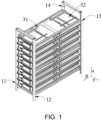
FIG. 1 is a first schematic three-dimensional view of a structure of an energy storage rack according to an embodiment of the disclosure. -
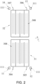
FIG. 2 is a schematic cross-sectional view of the structure of the energy storage rack according to an embodiment of the disclosure. -
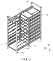
FIG. 3 is a second schematic three-dimensional view of the structure of the energy storage rack according to an embodiment of the disclosure. -
FIG. 4 is a schematic side view of the structure of the energy storage rack in a second direction according to an embodiment of the disclosure. -
FIG. 5 is a schematic three-dimensional view of a structure of a frame according to an embodiment of the disclosure. -
FIG. 6 is a schematic side view of the structure of the frame in the second direction according to an embodiment of the disclosure. -
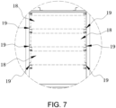
FIG. 7 is a schematic local enlargement view ofFIG. 6 . -
FIG. 8 is a schematic local enlargement view ofFIG. 1 . -
FIG. 9 is a schematic local enlargement view ofFIG. 4 . -
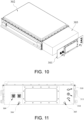
FIG. 10 is a schematic exploded view of a structure of a battery pack according to an embodiment of the disclosure. -
FIG. 11 is a schematic view of a structure of a panel on a first battery pack according to an embodiment of the disclosure. -
FIG. 12 is a schematic side view of the structure of the energy storage rack in a third direction according to an embodiment of the disclosure. -
FIG. 13 is a schematic view of a position of a general communicating port according to an embodiment of the disclosure. -
FIG. 14 is a schematic three-dimensional view of a structure of an energy storage aggregate according to an embodiment of the disclosure. -
FIG. 15 is a schematic side view of the structure of the energy storage aggregate in the second direction according to an embodiment of the disclosure. -
FIG. 16 is a schematic cross-sectional view of a structure of an integrated vertical beam according to an embodiment of the disclosure. -
FIG. 17 is a schematic three-dimensional view of a structure of an energy storage container according to an embodiment of the disclosure. -
FIG. 18 is a schematic side view of the structure of the energy storage container in the second direction according to an embodiment of the disclosure. -
FIG. 19 is a schematic three-dimensional view of arrangement of energy storage aggregates in the energy storage container according to an embodiment of the disclosure. -
FIG. 20 is a schematic top view of the arrangement of the energy storage aggregates in the energy storage container according to an embodiment of the disclosure. -
FIG. 21 is a schematic side view of the arrangement of the energy storage aggregates in the energy storage container according to an embodiment of the disclosure. - The implementation of the disclosure is illustrated below by specific embodiments. A person having ordinary skill in the art can easily understand other advantages and effects of the disclosure from the content disclosed in this specification.
- With reference to
FIG. 1 to FIG. 21 , it should be noted that the structures, scales, sizes, etc. shown in the accompanying drawings in the specification are only to be used together with the content disclosed in the specification for a person having ordinary skill in the art to comprehend and read, are not intended to define the defining conditions of the implementation of the disclosure, and therefore have no technical significance. Any structural modification, proportional relationship change, or size adjustment, without affecting the effects and objectives that can be achieved by the disclosure, should still fall within the scope of the technical content disclosed in the disclosure. Further, terms such as "upper", "lower", "left", "right", "middle", and "one" quoted in this specification are only for the convenience of description and are not used to define the applicable scope of the disclosure. The change or adjustment of its relative relationship should also be regarded as the applicable scope of the disclosure without substantive change of the technical content. - With reference to
FIG. 1 to FIG. 13 , this embodiment provides anenergy storage rack 10 including a frame 1 provided with a plurality of layers ofaccommodation spaces 18 stacked in a first direction α. The frame 1 includes four vertical beams all arranged in the first direction α, and aflow channel 111 is arranged in each of the four vertical beams. - To be specific, the fourth vertical beams respectively are a first
vertical beam 11, a secondvertical beam 12, a thirdvertical beam 13, and a fourthvertical beam 14. In a second direction β, the firstvertical beam 11 and the secondvertical beam 12 are located on one side of theaccommodation spaces 18, and the thirdvertical beam 13 and the fourthvertical beam 14 are located on the other side of theaccommodation spaces 18 relative to the firstvertical beam 11 and the secondvertical beam 12. The second direction β is perpendicular to the first direction α. - Two battery packs are arranged in each of the accommodation spaces, and the two battery packs are a
first battery pack 31 and asecond battery pack 32. Thefirst battery pack 31 is arranged close to the firstvertical beam 11 and the secondvertical beam 12, and thesecond battery pack 32 is arranged close to the thirdvertical beam 13 and the fourthvertical beam 14. - As shown in
FIG. 2 , a heatexchange flow channel 308 is provided in each of thefirst battery pack 31 and thesecond battery pack 32. Thefirst battery pack 31 has afirst inlet 304 for a heat exchange medium to flow in and afirst outlet 305 for the heat exchange medium to flow out, and the heatexchange flow channel 308 of thefirst battery pack 31 communicates with thefirst inlet 304 and thefirst outlet 305. Thesecond battery pack 32 has asecond inlet 306 for the heat exchange medium to flow in and asecond outlet 307 for the heat exchange medium to flow out, and the heatexchange flow channel 308 of thesecond battery pack 32 communicates with thesecond inlet 306 and thesecond outlet 307. - The
first inlet 304 and thefirst outlet 305 of thefirst battery pack 31 are arranged close to the firstvertical beam 11 and the secondvertical beam 12, and thesecond inlet 306 and thesecond outlet 307 of thesecond battery pack 32 are arranged close to the thirdvertical beam 13 and the fourthvertical beam 14. - The
first inlet 304 communicates with theflow channel 111 of the firstvertical beam 11, and thefirst outlet 305 communicates with theflow channel 111 of the secondvertical beam 12. Thesecond inlet 306 communicates with theflow channel 111 of the thirdvertical beam 13, and thesecond outlet 307 communicates with theflow channel 111 of the fourthvertical beam 14. - The heat
exchange flow channels 308 are used for heat exchange with inner portions of the battery packs, so that the temperature of the battery packs may be kept in a suitable temperature range, and that the energy storage efficiency, charging and discharging efficiency, and safety performance of the battery packs may be kept. - In some embodiments, the heat
exchange flow channels 308 may be arranged in heat exchange components such as heat exchange plates, and the heat exchange components are separately arranged and assembled in the battery packs, so assembly and maintenance may be easily performed. However, the presence of the heat exchange components increases the number of components and parts in the battery packs and occupies a large space, so that the assembly steps are increased and the space utilization rate within ahousing body 302 is also reduced. - In some other embodiments, the heat
exchange flow channels 308 may be integrated into an inner wall of thehousing body 302, such as bottom portions of the battery packs, and do not need to be separately arranged. In this way, the number of components and parts in the battery packs is reduced, the assembly steps are simplified, and the available spaces in the battery packs are increased, so that the energy density of the battery packs is increased. However, the heatexchange flow channels 308 are integrated into the inner wall of thehousing body 302, so that the processing difficulty of thehousing body 302 increases, and replacement and maintenance of the heatexchange flow channels 308 may not be easily performed. - In some embodiments, only some of the
accommodation spaces 18 are provided with two battery packs, and the remainingaccommodation spaces 18 are not provided with a battery pack or are provided with only one battery pack. In this embodiment, eachaccommodation space 18 is provided with thefirst battery pack 31 and thesecond battery pack 32. The specific number of battery packs in theenergy storage rack 10 may be set according to the energy storage requirements of theenergy storage rack 10. When two battery packs are installed in each of theaccommodation spaces 18, theenergy storage rack 10 has the largest energy storage capacity and the highest energy density. - The
flow channel 111 is provided in each of the vertical beams, and theflow channel 111 communicates with the heatexchange flow channel 308 of the corresponding battery pack. Therefore, the heat exchange medium may enter the battery pack through the vertical beam to exchange heat with the battery pack, and the heat exchange medium after heat exchange may also flow out from the vertical beam. The arrangement of theflow channel 111 in each of the vertical beams replaces part of a heat exchange pipeline, so that the structure of theenergy storage rack 10 is simplified, the space occupied by the heat exchange pipelines is reduced, and the material costs and installation costs of the pipelines are lowered. It is beneficial to the miniaturization and lightweight of theenergy storage rack 10 and improves the energy density of theenergy storage rack 10. - The
first battery pack 31 is arranged close to the firstvertical beam 11 and the secondvertical beam 12 and thesecond battery pack 32 is arranged close to the thirdvertical beam 13 and the fourthvertical beam 14, that is, the two battery packs are arranged close to the corresponding vertical beams. When thefirst battery pack 31 is being connected to the firstvertical beam 11 or the secondvertical beam 12 or when thefirst battery pack 31 is being maintained, the connection or the maintenance may be made from the side of the frame 1 corresponding to the firstvertical beam 11 and the secondvertical beam 12. When thesecond battery pack 32 is being connected to the thirdvertical beam 13 or the fourthvertical beam 14 or when thesecond battery pack 32 is being maintained, the connection or the maintenance may be made from the side of the frame 1 corresponding to the thirdvertical beam 13 and the fourthvertical beam 14, which is simple and convenient. Further, the two battery packs are close to the corresponding vertical beams, so that the two battery packs are far away from each other, interference between the two battery packs is reduced, and connection and maintenance may be easily performed. In this embodiment, the vertical beams are made of profiles, and theflow channels 111 in the vertical beams may be directly extruded during profile extrusion without additional processing, so the overall costs are low. - In some embodiments, the
first outlet 305 is arranged close to the firstvertical beam 11, thefirst inlet 304 is arranged close to the secondvertical beam 12, thesecond outlet 307 is arranged close to the thirdvertical beam 13, and thesecond inlet 306 is arranged close to the fourthvertical beam 14. In this embodiment, thefirst outlet 305 is arranged close to the secondvertical beam 12, thefirst inlet 304 is arranged close to the firstvertical beam 11, thesecond inlet 306 is arranged close to the thirdvertical beam 13, and thesecond outlet 307 is arranged close to the fourthvertical beam 14. Thefirst inlet 304, thefirst outlet 305, thesecond inlet 306, and thesecond outlet 307 are close to the connected vertical beams, so that connection or maintenance between the vertical beams and the corresponding battery packs may be easily performed. - In some embodiments, the first direction α is set in a horizontal direction, that is, the
multi-layer accommodation spaces 18 are stacked in sequence in the horizontal direction. As shown inFIG. 1 ,FIG. 2 , andFIG. 4 , in this embodiment, the first direction α is set in a vertical direction, the second direction β is set in the horizontal direction, and themulti-layer accommodation spaces 18 are stacked in sequence in the vertical direction, so that the space in a height direction may be fully utilized, and the space utilization of theenergy storage rack 10 may be improved. Further, when the battery packs are installed or disassembled, the battery packs may enter theaccommodation spaces 18 in the horizontal direction, which is convenient for an operator to operate. - As shown in
FIG. 2 andFIG. 8 toFIG. 11 , in this embodiment, each of the battery packs includes apanel 301, thefirst inlet 304 and thefirst outlet 305 of thefirst battery pack 31 are arranged on thepanel 301 of thefirst battery pack 31, and thesecond inlet 306 and thesecond outlet 307 of thesecond battery pack 32 are arranged on thepanel 301 of thesecond battery pack 32. The side where thepanel 301 is located is an operating side of each of the battery pack. Thepanel 301 of thefirst battery pack 31 is located on a side surface of thefirst battery pack 31 close to the firstvertical beam 11 and the secondvertical beam 12, and thepanel 301 of thesecond battery pack 32 is located on a side surface of thesecond battery pack 32 close to the thirdvertical beam 13 and the fourthvertical beam 14. Operations such as connecting and maintaining thepanel 301 of thefirst battery pack 31 may be performed from the positions of the firstvertical beam 11 and the secondvertical beam 12, and operations such as connecting and maintaining thepanel 301 of thesecond battery pack 32 may be performed from the positions of the thirdvertical beam 13 and the fourthvertical beam 14, so these operations may be easily performed. - In this embodiment, each of the battery packs includes a charging and discharging
port 309 and acommunication port 310. As shown inFIG. 11 , the charging and dischargingport 309 and thecommunication port 310 are also arranged on thepanel 301. To be specific, the charging and dischargingport 309 is a high-voltage port including a charging port and a discharging port. The charging port is used to charge the battery pack, and the discharging port is used to output electric energy from the battery pack. Thecommunication port 310 is a low-voltage port, and communication information, sensor detection results, and low-voltage power supply are all output through thecommunication port 310. In this embodiment, an explosion-proof valve 311 of the battery pack is also arranged on thepanel 301. The explosion-proof valve 311 may relieve the pressure of the battery pack when the pressure in the battery pack exceeds the safety threshold, prevent the battery pack from exploding, and improve the safety performance of the battery pack. - As shown in
FIG. 10 , in this embodiment, each of the battery packs includes thehousing body 302 and a battery assembly, thepanel 301 and thehousing body 302 is detachably connected, and the battery assembly is arranged in an internal space surrounded by thehousing body 302 and thepanel 301. The battery assembly is used to store electric energy, and thehousing body 302 and thepanel 301 are used to fix, support, and protect the battery assembly. Thepanel 301 and thehousing body 302 are arranged separately, and thepanel 301 and thehousing body 302 are detachably connected, so maintenance and replacement of thepanel 301 may be easily performed. - To be specific, in this embodiment, the
housing body 302 has an installation opening through which the battery assembly may enter and exit thehousing body 302, and thepanel 301 is detachably connected onto the installation opening. When thepanel 301 is connected to the installation opening, thehousing body 302 and thepanel 301 are combined to form a complete housing body. When thepanel 301 is detached, the battery assembly may enter and exit thehousing body 302 through the installation opening, so that the battery assembly may be easily repaired and replaced. - As shown in
FIG. 2 ,FIG. 8 , andFIG. 9 , theenergy storage rack 10 further includes a plurality of connectingpipes 17. Thefirst inlet 304 communicates with theflow channel 111 of the firstvertical beam 11 through the corresponding connectingpipe 17, thefirst outlet 305 communicates with theflow channel 111 of the secondvertical beam 12 through the corresponding connectingpipe 17, thesecond inlet 306 communicates with theflow channel 111 of the thirdvertical beam 13 through the corresponding connectingpipe 17, and thesecond outlet 307 communicates with theflow channel 111 of the fourthvertical beam 14 through the corresponding connectingpipe 17. Thefirst inlet 304, thefirst outlet 305, thesecond inlet 306, and thesecond outlet 307 may be connected to the corresponding vertical beams through the corresponding connectingpipes 17, so that compared with the direct connection between the battery packs and the vertical beams, the relative position requirements between the battery packs and the vertical beams may be reduced, and the difficulty of processing and installation may be lowered. Further, the corresponding moderate increase in the distance between the battery packs and the vertical beams is conducive to increasing the operating space when the battery packs are connected to the vertical beams. - To be specific, each of the connecting
pipes 17 is a flexible hose in this embodiment. The flexible hose may be bent and deformed according to the installation position, so that the position accuracy and processing accuracy requirements between the battery packs and the corresponding vertical beams are lowered, and the connection between the vertical beams and battery packs may be easily performed. - In this embodiment, each of the
first inlet 304, thefirst outlet 305, thesecond inlet 306, and thesecond outlet 307 is provided with a quick connector. Each of thefirst inlet 304, thefirst outlet 305, thesecond inlet 306, and thesecond outlet 306 communicates with the corresponding connectingpipe 17 through the quick connector. - In this embodiment, each of the vertical beams is also provided with a quick connector communicating with the
flow channel 111 in the vertical beam, and the connectingpipes 17 communicate with theflow channels 111 in the vertical beams through the quick connectors. - In actual situations, one end of each of the connecting
pipes 17 may be connected to the corresponding vertical beam in advance. When the battery packs are installed in accommodation chambers, the other ends of the connectingpipes 17 are connected to the quick connectors on the battery packs, so the heatexchange flow channels 308 in the battery packs may communicate with thecorresponding flow channels 111 in the vertical beams, which is convenient and fast. - As shown in
FIG. 6 andFIG. 7 , in this embodiment, the frame further includes connectingmembers 16, and the connectingmembers 16 are connected to the four vertical beams. There are a plurality of connectingmembers 16, and the plurality of connectingmembers 16 are sequentially arranged in the first direction α and form theaccommodation spaces 18 in the frame. - The connecting
members 16 may be in the form of plates or shelves, and the connectingmembers 16 divide the space in the frame into the plurality ofaccommodation spaces 18. In this embodiment, the connectingmembers 16 include two opposite supporting cross beams 19. One supportingcross beam 19 is connected to the firstvertical beam 11 and the fourthvertical beam 14, and the other supportingcross beam 19 is connected to the secondvertical beam 12 and the thirdvertical beam 13. When the battery packs are installed in theaccommodation spaces 18, the supportingcross beams 19 support the battery packs. - As shown in
FIG. 3 andFIG. 12 , in this embodiment, the frame further includes auxiliary supportingbeams 15 arranged in the first direction α and connected to the connectingmembers 16. Theauxiliary supporting beams 15 may increase the structural strength of the frame in the first direction α, so that the frame may carry more battery packs in the first direction α. In some embodiments, the frame may also include other reinforcing beams to enhance the structural strength of the frame and avoid deformation of the frame. - As shown in
FIG. 9 , in this embodiment, a general communicatingport 102 is provided on an end portion of each of the vertical beams corresponding to the vertical beam, and the general communicatingport 102 communicates with the flow channel in the vertical beam. The general communicatingport 102 is configured to communicate with a medium input pipeline or a medium output pipeline. The heat exchange medium may enter the flow channel of the vertical beam through the general communicatingport 102 and then enters each battery pack through the flow channel for heat exchange. The heat exchange medium after heat exchange flows out from each battery pack, enters the flow channel of another vertical beam, and is discharged from the general communicatingport 102 of the vertical beam. The general communicatingport 102 is provided corresponding to the end portion of the vertical beam, avoiding the battery pack, so that the general communicatingport 102 may be easily connected to the medium input pipeline or the medium output pipeline. - As shown in
FIG. 14 to FIG. 21 , the disclosure further provides an energy storage container including acontainer body 20 and a plurality of the abovementioned energy storage racks 10 arranged in thecontainer body 20. The energy storage racks 10 are arranged side by side in a third direction γ perpendicular to the first direction α and the second direction β. - In this embodiment, the direction in which the plurality of energy storage racks 10 are arranged side by side is perpendicular to the direction in which the two battery packs in the
energy storage rack 10 are connected. Since the battery packs are inspected from the second direction β and eachenergy storage rack 10 is arranged in the third direction y, thepanels 301 of the battery packs are all exposed. Adjacent energy storage racks 10 may not block the maintenance paths of the battery packs, so the maintenance of the battery packs may be easily performed. - In this embodiment, the first
vertical beam 11 is spaced apart from the secondvertical beam 12 in the third direction γ, and thefirst battery pack 31 enters and exits theaccommodation space 18 through a gap between the firstvertical beam 11 and the secondvertical beam 12. The thirdvertical beam 13 is spaced apart from the fourthvertical beam 14 in the third direction γ, and thesecond battery pack 32 enters and exits theaccommodation space 18 through a gap between the thirdvertical beam 13 and the fourthvertical beam 14. Since the plurality of energy storage racks 10 are arranged side by side in the second direction β, the adjacent energy storage racks 10 may not block the detachment and installation paths of the battery packs, so the installation and detachment of the battery packs may be easily performed. - As shown in
FIG. 16 , in this embodiment, the two vertical beams that are close to each other between two adjacent energy storage racks 10 are combined into an integratedvertical beam 101, and the twoflow channels 111 in the integratedvertical beam 101 are separated from each other. The twoflow channels 111 in the integratedvertical beam 101 may be obtained at the same time during extrusion and forming without being additionally arranged, so the structure of the frame is simplified, and the material costs of the frame are also decreased. -
Container doors 21 are provided on a side surface of thecontainer body 20 relative to the energy storage racks 10 in the second direction β. Thecontainer doors 21 are opened on the side surface of thecontainer body 20 in the second direction β. In this way, after thecontainer doors 21 are opened, thepanels 301 of the battery packs, that is, the connection positions between the battery packs and the corresponding vertical beams, are exposed in thecontainer doors 21, so an operator can operate the battery packs through thecontainer doors 21. - In this embodiment, the
container body 20 is provided with twoopposite container doors 21 corresponding to the sameenergy storage rack 10, and the twocontainer doors 21 are provided corresponding to both sides of theenergy storage rack 10 in the second direction β. When there are multiple energy storage racks 10, the number ofcontainer doors 21 also increases accordingly. To be specific, in this embodiment, there are four energy storage racks 10 and eightcontainer doors 21, and the eightcontainer doors 21 are arranged on both sides of thecontainer body 20. - As shown in
FIG. 19 to FIG. 21 , the energy storage racks 10 are arranged side by side into two energy storage aggregates 100 spaced apart from each other in the second direction β, and a gap between the two energy storage aggregates 100 is anaisle 201 for an operator to pass through. The operator may connect or inspect thepanels 301 of the battery packs located on the outward sides of the two energy storage aggregates 100 through thecontainer doors 21 outside thecontainer body 20. The operator may also perform connection or maintenance operations through thepanels 301 of the battery packs located on both sides of theaisle 201. In this way, all battery packs may be connected or inspected without additional detachment of the frame or thecontainer body 20, which is simple and convenient. - In view of the foregoing, in the energy storage rack and the energy storage container provided by the embodiments, since each of the vertical beams is provided with the
flow channel 111 and theflow channel 111 communicates with the heat exchange flow channel of the corresponding battery pack, the heat exchange medium may enter the battery pack through the vertical beam to exchange heat with the battery pack, and the heat exchange medium after heat exchange may flow out from the vertical beam. The arrangement of theflow channel 111 in each of the vertical beams replaces part of the heat exchange pipeline, so that the structure of theenergy storage rack 10 is simplified, the space occupied by the heat exchange pipelines is reduced, and the material costs and installation costs of the pipelines are lowered. It is beneficial to the miniaturization and lightweight of theenergy storage rack 10 and improves the energy density of theenergy storage rack 10. - In the meantime, the first
vertical beam 11 and the secondvertical beam 12 are located on one side of theaccommodation spaces 18, the thirdvertical beam 13 and the fourthvertical beam 14 are located on the other side of theaccommodation spaces 18 relative to the firstvertical beam 11 and the second vertical beam 1, thefirst battery pack 31 is arranged close to the firstvertical beam 11 and the secondvertical beam 12, and thesecond battery pack 32 is arranged close to the thirdvertical beam 13 and the fourthvertical beam 14. That is, the four vertical beams are all arranged on the outside of the frame, and the two battery packs are close to the corresponding vertical beams. When the vertical beams and the battery packs are to be connected or maintenance on the battery packs is to be performed, the connection or maintenance may be carried out from the side of the frame where the vertical beams close to the battery packs are located, which is simple and convenient. Further, the two battery packs are close to the corresponding vertical beams, so that the two battery packs are far away from each other, the interference between the two battery packs is reduced, and connection between the battery packs and the vertical beams and maintenance on the battery packs may be easily performed. - The above-mentioned embodiments only illustrate the principles and effects of the disclosure, but are not intended to limit the disclosure. A person having ordinary skill in the art can modify or change the abovementioned embodiments without departing from the spirit and scope of the disclosure. Therefore, all equivalent modifications or changes made by a person having ordinary skill in the art without departing from the spirit and technical ideas disclosed in the disclosure shall still be covered by the claims of the disclosure.
-
- 1: frame,
- 10: energy storage rack,
- 11: first vertical beam,
- 12: second vertical beam,
- 13: third vertical beam,
- 14: fourth vertical beam,
- 15: auxiliary supporting beam,
- 16: connecting member,
- 17: connecting pipe,
- 18: accommodation space,
- 19: supporting cross beam,
- 20: container body,
- 21: container door,
- 31: first battery pack,
- 32: second battery pack,
- 301: panel,
- 302: housing body,
- 303: battery assembly,
- 304: first inlet,
- 305: first outlet,
- 306: second inlet,
- 307: second outlet,
- 308: heat exchange flow channel,
- 309: charging and discharging port,
- 310: communication port,
- 311: explosion-proof valve,
- 100: energy storage aggregate,
- 101: integrated vertical beam,
- 102: general communicating port,
- 111: flow channel,
- 201: aisle,
- α: first direction,
- β: second direction,
- γ: third direction.
Claims (15)
- An energy storage rack (10), comprising:a frame (1) provided with a plurality of layers of accommodation spaces (18) stacked in a first direction (α), wherein the frame (1) comprises four vertical beams arranged in the first direction (α), the four vertical beams are a first vertical beam (11), a second vertical beam (12), a third vertical beam (13), and a fourth vertical beam (14), and a flow channel (111) is arranged in each of the four vertical beams,in a second direction (β) perpendicular to the first direction (α), the first vertical beam (11) and the second vertical beam (12) are located on one side of the accommodation spaces (18), and the third vertical beam (13) and the fourth vertical beam (14) are located on the other side of the accommodation spaces (18) opposite to the first vertical beam (11) and the second vertical beam (12),two battery packs (31, 32) are arranged in each of the accommodation space (18) of each layer, the two battery packs (31, 32) respectively are a first battery pack (31) and a second battery pack (32), the first battery pack (31) is arranged close to the first vertical beam (11) and the second vertical beam (12), and the second battery pack (32) is arranged close to the third vertical beam (13) and the fourth vertical beam (14),the first battery pack (31) has a first inlet (304) for a heat exchange medium to flow in and a first outlet (305) for the heat exchange medium to flow out, and the second battery pack (32) has a second inlet (306) for the heat exchange medium to flow in and a second outlet (307) for the heat exchange medium to flow out,a heat exchange flow channel (308) is provided in each of the battery packs, the heat exchange flow channel (308) of the first battery pack (31) communicates with the first inlet (304) and the first outlet (305), and the heat exchange flow channel (308) of the second battery pack (32) communicates with the second inlet (306) and the second outlet (307),the first inlet (304) and the first outlet (305) are arranged close to the first vertical beam (11) and the second vertical beam (12), and the second inlet (306) and the second outlet (307) are arranged close to the third vertical beam (13) and the fourth vertical beam (14), andthe first inlet (304) communicates with the flow channel (111) of the first vertical beam (11), the first outlet (305) communicates with the flow channel (111) of the second vertical beam (12), the second inlet (306) communicates with the flow channel (111) of the third vertical beam (13), and the second outlet (307) communicates with the flow channel (111) of the fourth vertical beam (14).
- The energy storage rack (10) according to claim 1, wherein each of the battery packs (31, 32) comprises a panel (301), the first inlet (304) and the first outlet (305) are arranged on the panel (301) of the first battery pack (31), the second inlet (306) and the second outlet (307) are arranged on the panel (301) of the second battery pack (32), the panel (301) of the first battery pack (31) is located on a side surface of the first battery pack (31) close to the first vertical beam (11) and the second vertical beam (12), and the panel (301) of the second battery pack (32) is located on a side surface of the second battery pack (32) close to the third vertical beam (13) and the fourth vertical beam (14).
- The energy storage rack (10) according to claim 2, wherein each of the battery packs (31, 32) comprises a housing body (302) and a battery assembly (303), the panel (301) and the housing body (302) are detachably connected, and the battery assembly (303) is arranged in a space surrounded by the housing body (302) and the panel (301).
- The energy storage rack (10) according to claim 2, wherein the panel (301) is provided with a communication port (310) and a charging and discharging port (309).
- The energy storage rack (10) according to claim 1, further comprising a plurality of connecting pipe (17)s arranged corresponding to the first inlet (304), the first outlet (305), the second inlet (306), and the second outlet (307), wherein the first inlet (304) communicates with the flow channel (111) of the first vertical beam (11) through corresponding one of the connecting pipes (17), the first outlet (305) communicates with the flow channel (111) of the second vertical beam (12) through corresponding one of the connecting pipes (17), the second inlet (306) communicates with the flow channel (111) of the third vertical beam (13) through corresponding one of the connecting pipes (17), and the second outlet (307) communicates with the flow channel (111) of the fourth vertical beam (14) through corresponding one of the connecting pipes (17).
- The energy storage rack (10) according to claim 5, wherein each of the connecting pipes (17) is a flexible hose.
- The energy storage rack (10) according to claim 5, wherein each of the first inlet (304), the first outlet (305), the second inlet (306), and the second outlet (307) is provided with a quick connector, and each of the first inlet (304), the first outlet (305), the second inlet (306), and the second outlet (307) communicates with corresponding one of the connecting pipes (17) through the quick connector.
- The energy storage rack (10) according to claim 1, wherein the frame (1) further comprises a plurality of connecting members (16), and the connecting members (16) are respectively connected to the four vertical beams and are arranged sequentially in the first direction (α) to form the accommodation spaces (18) in the frame (1).
- The energy storage rack (10) according to claim 8, wherein the frame (1) further comprises auxiliary supporting beams (15) arranged in the first direction (α) and respectively connected to each of the connecting members (16).
- The energy storage rack (10) according to claim 1, wherein a general communicating port (102) is provided on an end portion of each of the vertical beams corresponding to the vertical beam, and the general communicating port (102) communicates with the flow channel (111) in the vertical beam.
- An energy storage container comprising:a container body (20); anda plurality of energy storage racks (10) arranged in the container body (20) according to claim 1, wherein the energy storage racks (10) are arranged side by side in a third direction (γ) perpendicular to the first direction (α) and the second direction (β).
- The energy storage container according to claim 11, wherein the first vertical beam (11) is spaced apart from the second vertical beam (12) in the third direction (γ), the first battery pack (31) enters and exits the accommodation space (18) through a gap between the first vertical beam (11) and the second vertical beam (12), the third vertical beam (13) is spaced apart from the fourth vertical beam (14) in the third direction (γ), and the second battery pack (32) enters and exits the accommodation space (18) through a gap between the third vertical beam (13) and the fourth vertical beam (14).
- The energy storage container according to claim 11, wherein the two vertical beams that are close to each other between adjacent two of the energy storage racks (10) are combined into an integrated vertical beam (101), and two of the flow channels (111) in the integrated vertical beam (101) are separated from each other.
- The energy storage container according to claim 11, wherein container doors (21) are provided on a side surface of the container body (20) relative to the energy storage racks (10) in the second direction (β).
- The energy storage container according to claim 11, wherein the energy storage racks (10) are arranged side by side into two energy storage aggregates (100) spaced apart from each other in the second direction (β), and a gap between the two energy storage aggregates (100) is used for an operator to pass through.
Applications Claiming Priority (1)
| Application Number | Priority Date | Filing Date | Title |
|---|---|---|---|
| CN202321791879.7U CN220628018U (en) | 2023-07-10 | 2023-07-10 | Energy storage cluster and energy storage container |
Publications (2)
| Publication Number | Publication Date |
|---|---|
| EP4492537A1 true EP4492537A1 (en) | 2025-01-15 |
| EP4492537B1 EP4492537B1 (en) | 2025-06-25 |
Family
ID=89222431
Family Applications (1)
| Application Number | Title | Priority Date | Filing Date |
|---|---|---|---|
| EP23216107.5A Active EP4492537B1 (en) | 2023-07-10 | 2023-12-13 | Energy storage rack and energy storage container |
Country Status (5)
| Country | Link |
|---|---|
| US (1) | US20250023167A1 (en) |
| EP (1) | EP4492537B1 (en) |
| JP (1) | JP7709507B2 (en) |
| CN (1) | CN220628018U (en) |
| ES (1) | ES3039268T3 (en) |
Citations (4)
| Publication number | Priority date | Publication date | Assignee | Title |
|---|---|---|---|---|
| CN113644359A (en) * | 2021-08-11 | 2021-11-12 | 傲普(上海)新能源有限公司 | Battery rack for energy storage system, battery temperature control system and energy storage system |
| CN113707966A (en) * | 2021-09-03 | 2021-11-26 | 山东希格斯新能源有限责任公司 | Temperature control battery rack and energy storage power station composed of same |
| CN216354424U (en) * | 2021-11-12 | 2022-04-19 | 宁德时代新能源科技股份有限公司 | Thermal management system for energy storage device and energy storage device |
| CN114530643A (en) * | 2020-10-30 | 2022-05-24 | 恒大新能源技术(深圳)有限公司 | Battery pack box and battery pack |
Family Cites Families (5)
| Publication number | Priority date | Publication date | Assignee | Title |
|---|---|---|---|---|
| KR101278506B1 (en) | 2011-04-25 | 2013-07-02 | 주식회사 엘지화학 | Rack system of battery module for energy storage |
| JP7127586B2 (en) | 2019-03-15 | 2022-08-30 | 株式会社豊田自動織機 | Battery pack and power storage system |
| KR102743901B1 (en) | 2019-06-05 | 2024-12-16 | 주식회사 엘지에너지솔루션 | Battery rack and energy storage system comprising the same |
| KR102906401B1 (en) | 2019-08-30 | 2025-12-30 | 주식회사 엘지에너지솔루션 | Battery rack and energy storage system comprising the battery rack |
| KR102716975B1 (en) | 2019-10-30 | 2024-10-11 | 주식회사 엘지에너지솔루션 | Battery module, battery rack and energy storage system comprising the battery module |
-
2023
- 2023-07-10 CN CN202321791879.7U patent/CN220628018U/en active Active
- 2023-12-10 US US18/534,707 patent/US20250023167A1/en active Pending
- 2023-12-12 JP JP2023209677A patent/JP7709507B2/en active Active
- 2023-12-13 ES ES23216107T patent/ES3039268T3/en active Active
- 2023-12-13 EP EP23216107.5A patent/EP4492537B1/en active Active
Patent Citations (4)
| Publication number | Priority date | Publication date | Assignee | Title |
|---|---|---|---|---|
| CN114530643A (en) * | 2020-10-30 | 2022-05-24 | 恒大新能源技术(深圳)有限公司 | Battery pack box and battery pack |
| CN113644359A (en) * | 2021-08-11 | 2021-11-12 | 傲普(上海)新能源有限公司 | Battery rack for energy storage system, battery temperature control system and energy storage system |
| CN113707966A (en) * | 2021-09-03 | 2021-11-26 | 山东希格斯新能源有限责任公司 | Temperature control battery rack and energy storage power station composed of same |
| CN216354424U (en) * | 2021-11-12 | 2022-04-19 | 宁德时代新能源科技股份有限公司 | Thermal management system for energy storage device and energy storage device |
Also Published As
| Publication number | Publication date |
|---|---|
| JP7709507B2 (en) | 2025-07-16 |
| ES3039268T3 (en) | 2025-10-20 |
| CN220628018U (en) | 2024-03-19 |
| US20250023167A1 (en) | 2025-01-16 |
| JP2025011014A (en) | 2025-01-23 |
| EP4492537B1 (en) | 2025-06-25 |
Similar Documents
| Publication | Publication Date | Title |
|---|---|---|
| CN114512759B (en) | Single battery, power battery pack and electric vehicle | |
| CN116315372A (en) | A box for an energy storage device, an energy storage device, and an energy storage system | |
| EP3706222B1 (en) | Redox flow battery | |
| EP4492537B1 (en) | Energy storage rack and energy storage container | |
| CN218996851U (en) | Liquid cooling heat dissipation non-welding grouping structure of battery pack, battery pack and power battery box | |
| CN117254181A (en) | a battery system | |
| CN218586160U (en) | Energy storage warehouse and energy storage system | |
| CN219642904U (en) | Formation equipment | |
| CN220086171U (en) | Liquid cooling battery rack and battery package | |
| EP4571940A1 (en) | Integrated battery module | |
| CN223651461U (en) | Cooling pipeline, cooling module and energy storage system | |
| CN219476907U (en) | Submerged liquid cooling energy storage system | |
| CN219873994U (en) | Battery pack | |
| CN222637464U (en) | Energy storage container | |
| CN224217480U (en) | Integrated energy storage container and assembly thereof | |
| CN218919162U (en) | Battery pack lower box and battery pack | |
| CN220963492U (en) | Integrated battery box | |
| CN223363170U (en) | Energy storage power station and liquid flow energy storage tank | |
| CN223170894U (en) | Parallel double-layer heat exchange plate type reactor | |
| CN223771187U (en) | Energy storage devices and energy storage systems | |
| CN224020825U (en) | Cooling pipeline, cooling module and energy storage system | |
| CN221727401U (en) | Large-capacity battery and cylinder assembly for large-capacity battery | |
| CN117559063A (en) | Tower type energy storage system and energy storage station house with same | |
| WO2025086744A1 (en) | Container, energy storage apparatus, energy storage system and charging network | |
| WO2026103147A1 (en) | Battery pack and energy storage cabinet |
Legal Events
| Date | Code | Title | Description |
|---|---|---|---|
| PUAI | Public reference made under article 153(3) epc to a published international application that has entered the european phase |
Free format text: ORIGINAL CODE: 0009012 |
|
| STAA | Information on the status of an ep patent application or granted ep patent |
Free format text: STATUS: REQUEST FOR EXAMINATION WAS MADE |
|
| 17P | Request for examination filed |
Effective date: 20231213 |
|
| AK | Designated contracting states |
Kind code of ref document: A1 Designated state(s): AL AT BE BG CH CY CZ DE DK EE ES FI FR GB GR HR HU IE IS IT LI LT LU LV MC ME MK MT NL NO PL PT RO RS SE SI SK SM TR |
|
| GRAP | Despatch of communication of intention to grant a patent |
Free format text: ORIGINAL CODE: EPIDOSNIGR1 |
|
| STAA | Information on the status of an ep patent application or granted ep patent |
Free format text: STATUS: GRANT OF PATENT IS INTENDED |
|
| RIC1 | Information provided on ipc code assigned before grant |
Ipc: H01M 10/6568 20140101ALI20250129BHEP Ipc: H01M 10/613 20140101AFI20250129BHEP |
|
| INTG | Intention to grant announced |
Effective date: 20250213 |
|
| GRAS | Grant fee paid |
Free format text: ORIGINAL CODE: EPIDOSNIGR3 |
|
| GRAA | (expected) grant |
Free format text: ORIGINAL CODE: 0009210 |
|
| STAA | Information on the status of an ep patent application or granted ep patent |
Free format text: STATUS: THE PATENT HAS BEEN GRANTED |
|
| AK | Designated contracting states |
Kind code of ref document: B1 Designated state(s): AL AT BE BG CH CY CZ DE DK EE ES FI FR GB GR HR HU IE IS IT LI LT LU LV MC ME MK MT NL NO PL PT RO RS SE SI SK SM TR |
|
| REG | Reference to a national code |
Ref country code: GB Ref legal event code: FG4D |
|
| REG | Reference to a national code |
Ref country code: CH Ref legal event code: EP |
|
| REG | Reference to a national code |
Ref country code: DE Ref legal event code: R096 Ref document number: 602023004317 Country of ref document: DE |
|
| REG | Reference to a national code |
Ref country code: CH Ref legal event code: EP |
|
| REG | Reference to a national code |
Ref country code: IE Ref legal event code: FG4D |
|
| PG25 | Lapsed in a contracting state [announced via postgrant information from national office to epo] |
Ref country code: FI Free format text: LAPSE BECAUSE OF FAILURE TO SUBMIT A TRANSLATION OF THE DESCRIPTION OR TO PAY THE FEE WITHIN THE PRESCRIBED TIME-LIMIT Effective date: 20250625 |
|
| REG | Reference to a national code |
Ref country code: LT Ref legal event code: MG9D |
|
| PG25 | Lapsed in a contracting state [announced via postgrant information from national office to epo] |
Ref country code: NO Free format text: LAPSE BECAUSE OF FAILURE TO SUBMIT A TRANSLATION OF THE DESCRIPTION OR TO PAY THE FEE WITHIN THE PRESCRIBED TIME-LIMIT Effective date: 20250925 Ref country code: GR Free format text: LAPSE BECAUSE OF FAILURE TO SUBMIT A TRANSLATION OF THE DESCRIPTION OR TO PAY THE FEE WITHIN THE PRESCRIBED TIME-LIMIT Effective date: 20250926 |
|
| PG25 | Lapsed in a contracting state [announced via postgrant information from national office to epo] |
Ref country code: BG Free format text: LAPSE BECAUSE OF FAILURE TO SUBMIT A TRANSLATION OF THE DESCRIPTION OR TO PAY THE FEE WITHIN THE PRESCRIBED TIME-LIMIT Effective date: 20250625 |
|
| PG25 | Lapsed in a contracting state [announced via postgrant information from national office to epo] |
Ref country code: HR Free format text: LAPSE BECAUSE OF FAILURE TO SUBMIT A TRANSLATION OF THE DESCRIPTION OR TO PAY THE FEE WITHIN THE PRESCRIBED TIME-LIMIT Effective date: 20250625 |
|
| REG | Reference to a national code |
Ref country code: ES Ref legal event code: FG2A Ref document number: 3039268 Country of ref document: ES Kind code of ref document: T3 Effective date: 20251020 |
|
| PG25 | Lapsed in a contracting state [announced via postgrant information from national office to epo] |
Ref country code: RS Free format text: LAPSE BECAUSE OF FAILURE TO SUBMIT A TRANSLATION OF THE DESCRIPTION OR TO PAY THE FEE WITHIN THE PRESCRIBED TIME-LIMIT Effective date: 20250925 |
|
| PG25 | Lapsed in a contracting state [announced via postgrant information from national office to epo] |
Ref country code: LV Free format text: LAPSE BECAUSE OF FAILURE TO SUBMIT A TRANSLATION OF THE DESCRIPTION OR TO PAY THE FEE WITHIN THE PRESCRIBED TIME-LIMIT Effective date: 20250625 |
|
| REG | Reference to a national code |
Ref country code: NL Ref legal event code: MP Effective date: 20250625 |
|
| PG25 | Lapsed in a contracting state [announced via postgrant information from national office to epo] |
Ref country code: NL Free format text: LAPSE BECAUSE OF FAILURE TO SUBMIT A TRANSLATION OF THE DESCRIPTION OR TO PAY THE FEE WITHIN THE PRESCRIBED TIME-LIMIT Effective date: 20250625 |
|
| PG25 | Lapsed in a contracting state [announced via postgrant information from national office to epo] |
Ref country code: PT Free format text: LAPSE BECAUSE OF FAILURE TO SUBMIT A TRANSLATION OF THE DESCRIPTION OR TO PAY THE FEE WITHIN THE PRESCRIBED TIME-LIMIT Effective date: 20251027 |
|
| REG | Reference to a national code |
Ref country code: AT Ref legal event code: MK05 Ref document number: 1807549 Country of ref document: AT Kind code of ref document: T Effective date: 20250625 |
|
| PG25 | Lapsed in a contracting state [announced via postgrant information from national office to epo] |
Ref country code: IS Free format text: LAPSE BECAUSE OF FAILURE TO SUBMIT A TRANSLATION OF THE DESCRIPTION OR TO PAY THE FEE WITHIN THE PRESCRIBED TIME-LIMIT Effective date: 20251025 |
|
| PGFP | Annual fee paid to national office [announced via postgrant information from national office to epo] |
Ref country code: DE Payment date: 20251022 Year of fee payment: 3 |
|
| PG25 | Lapsed in a contracting state [announced via postgrant information from national office to epo] |
Ref country code: AT Free format text: LAPSE BECAUSE OF FAILURE TO SUBMIT A TRANSLATION OF THE DESCRIPTION OR TO PAY THE FEE WITHIN THE PRESCRIBED TIME-LIMIT Effective date: 20250625 Ref country code: SM Free format text: LAPSE BECAUSE OF FAILURE TO SUBMIT A TRANSLATION OF THE DESCRIPTION OR TO PAY THE FEE WITHIN THE PRESCRIBED TIME-LIMIT Effective date: 20250625 |
|
| PGFP | Annual fee paid to national office [announced via postgrant information from national office to epo] |
Ref country code: FR Payment date: 20251023 Year of fee payment: 3 |
|
| PG25 | Lapsed in a contracting state [announced via postgrant information from national office to epo] |
Ref country code: CZ Free format text: LAPSE BECAUSE OF FAILURE TO SUBMIT A TRANSLATION OF THE DESCRIPTION OR TO PAY THE FEE WITHIN THE PRESCRIBED TIME-LIMIT Effective date: 20250625 |
|
| PG25 | Lapsed in a contracting state [announced via postgrant information from national office to epo] |
Ref country code: PL Free format text: LAPSE BECAUSE OF FAILURE TO SUBMIT A TRANSLATION OF THE DESCRIPTION OR TO PAY THE FEE WITHIN THE PRESCRIBED TIME-LIMIT Effective date: 20250625 |
|
| PG25 | Lapsed in a contracting state [announced via postgrant information from national office to epo] |
Ref country code: EE Free format text: LAPSE BECAUSE OF FAILURE TO SUBMIT A TRANSLATION OF THE DESCRIPTION OR TO PAY THE FEE WITHIN THE PRESCRIBED TIME-LIMIT Effective date: 20250625 |
|
| PG25 | Lapsed in a contracting state [announced via postgrant information from national office to epo] |
Ref country code: SK Free format text: LAPSE BECAUSE OF FAILURE TO SUBMIT A TRANSLATION OF THE DESCRIPTION OR TO PAY THE FEE WITHIN THE PRESCRIBED TIME-LIMIT Effective date: 20250625 |
|
| PG25 | Lapsed in a contracting state [announced via postgrant information from national office to epo] |
Ref country code: RO Free format text: LAPSE BECAUSE OF FAILURE TO SUBMIT A TRANSLATION OF THE DESCRIPTION OR TO PAY THE FEE WITHIN THE PRESCRIBED TIME-LIMIT Effective date: 20250625 |
|
| PGFP | Annual fee paid to national office [announced via postgrant information from national office to epo] |
Ref country code: ES Payment date: 20260115 Year of fee payment: 3 |
|
| PG25 | Lapsed in a contracting state [announced via postgrant information from national office to epo] |
Ref country code: DK Free format text: LAPSE BECAUSE OF FAILURE TO SUBMIT A TRANSLATION OF THE DESCRIPTION OR TO PAY THE FEE WITHIN THE PRESCRIBED TIME-LIMIT Effective date: 20250625 |
|
| PG25 | Lapsed in a contracting state [announced via postgrant information from national office to epo] |
Ref country code: IT Free format text: LAPSE BECAUSE OF FAILURE TO SUBMIT A TRANSLATION OF THE DESCRIPTION OR TO PAY THE FEE WITHIN THE PRESCRIBED TIME-LIMIT Effective date: 20250625 |
|
| PLBE | No opposition filed within time limit |
Free format text: ORIGINAL CODE: 0009261 |
|
| STAA | Information on the status of an ep patent application or granted ep patent |
Free format text: STATUS: NO OPPOSITION FILED WITHIN TIME LIMIT |
|
| REG | Reference to a national code |
Ref country code: CH Ref legal event code: L10 Free format text: ST27 STATUS EVENT CODE: U-0-0-L10-L00 (AS PROVIDED BY THE NATIONAL OFFICE) Effective date: 20260507 |