EP4492522A1 - Automatic separation jig for manufacturing battery module - Google Patents
Automatic separation jig for manufacturing battery module Download PDFInfo
- Publication number
- EP4492522A1 EP4492522A1 EP24777203.1A EP24777203A EP4492522A1 EP 4492522 A1 EP4492522 A1 EP 4492522A1 EP 24777203 A EP24777203 A EP 24777203A EP 4492522 A1 EP4492522 A1 EP 4492522A1
- Authority
- EP
- European Patent Office
- Prior art keywords
- automatic separation
- connector
- separation jig
- button
- slide unit
- Prior art date
- Legal status (The legal status is an assumption and is not a legal conclusion. Google has not performed a legal analysis and makes no representation as to the accuracy of the status listed.)
- Pending
Links
Images




Classifications
-
- H—ELECTRICITY
- H01—ELECTRIC ELEMENTS
- H01M—PROCESSES OR MEANS, e.g. BATTERIES, FOR THE DIRECT CONVERSION OF CHEMICAL ENERGY INTO ELECTRICAL ENERGY
- H01M50/00—Constructional details or processes of manufacture of the non-active parts of electrochemical cells other than fuel cells, e.g. hybrid cells
- H01M50/20—Mountings; Secondary casings or frames; Racks, modules or packs; Suspension devices; Shock absorbers; Transport or carrying devices; Holders
- H01M50/296—Mountings; Secondary casings or frames; Racks, modules or packs; Suspension devices; Shock absorbers; Transport or carrying devices; Holders characterised by terminals of battery packs
-
- H—ELECTRICITY
- H01—ELECTRIC ELEMENTS
- H01M—PROCESSES OR MEANS, e.g. BATTERIES, FOR THE DIRECT CONVERSION OF CHEMICAL ENERGY INTO ELECTRICAL ENERGY
- H01M10/00—Secondary cells; Manufacture thereof
- H01M10/04—Construction or manufacture in general
-
- H—ELECTRICITY
- H01—ELECTRIC ELEMENTS
- H01M—PROCESSES OR MEANS, e.g. BATTERIES, FOR THE DIRECT CONVERSION OF CHEMICAL ENERGY INTO ELECTRICAL ENERGY
- H01M10/00—Secondary cells; Manufacture thereof
- H01M10/04—Construction or manufacture in general
- H01M10/0404—Machines for assembling batteries
-
- H—ELECTRICITY
- H01—ELECTRIC ELEMENTS
- H01M—PROCESSES OR MEANS, e.g. BATTERIES, FOR THE DIRECT CONVERSION OF CHEMICAL ENERGY INTO ELECTRICAL ENERGY
- H01M10/00—Secondary cells; Manufacture thereof
- H01M10/42—Methods or arrangements for servicing or maintenance of secondary cells or secondary half-cells
- H01M10/4285—Testing apparatus
-
- H—ELECTRICITY
- H01—ELECTRIC ELEMENTS
- H01R—ELECTRICALLY-CONDUCTIVE CONNECTIONS; STRUCTURAL ASSOCIATIONS OF A PLURALITY OF MUTUALLY-INSULATED ELECTRICAL CONNECTING ELEMENTS; COUPLING DEVICES; CURRENT COLLECTORS
- H01R13/00—Details of coupling devices of the kinds covered by groups H01R12/70 or H01R24/00 - H01R33/00
- H01R13/62—Means for facilitating engagement or disengagement of coupling parts or for holding them in engagement
- H01R13/629—Additional means for facilitating engagement or disengagement of coupling parts, e.g. aligning or guiding means, levers, gas pressure electrical locking indicators, manufacturing tolerances
- H01R13/633—Additional means for facilitating engagement or disengagement of coupling parts, e.g. aligning or guiding means, levers, gas pressure electrical locking indicators, manufacturing tolerances for disengagement only
-
- H—ELECTRICITY
- H01—ELECTRIC ELEMENTS
- H01R—ELECTRICALLY-CONDUCTIVE CONNECTIONS; STRUCTURAL ASSOCIATIONS OF A PLURALITY OF MUTUALLY-INSULATED ELECTRICAL CONNECTING ELEMENTS; COUPLING DEVICES; CURRENT COLLECTORS
- H01R13/00—Details of coupling devices of the kinds covered by groups H01R12/70 or H01R24/00 - H01R33/00
- H01R13/62—Means for facilitating engagement or disengagement of coupling parts or for holding them in engagement
- H01R13/629—Additional means for facilitating engagement or disengagement of coupling parts, e.g. aligning or guiding means, levers, gas pressure electrical locking indicators, manufacturing tolerances
- H01R13/633—Additional means for facilitating engagement or disengagement of coupling parts, e.g. aligning or guiding means, levers, gas pressure electrical locking indicators, manufacturing tolerances for disengagement only
- H01R13/635—Additional means for facilitating engagement or disengagement of coupling parts, e.g. aligning or guiding means, levers, gas pressure electrical locking indicators, manufacturing tolerances for disengagement only by mechanical pressure, e.g. spring force
-
- H—ELECTRICITY
- H01—ELECTRIC ELEMENTS
- H01R—ELECTRICALLY-CONDUCTIVE CONNECTIONS; STRUCTURAL ASSOCIATIONS OF A PLURALITY OF MUTUALLY-INSULATED ELECTRICAL CONNECTING ELEMENTS; COUPLING DEVICES; CURRENT COLLECTORS
- H01R2201/00—Connectors or connections adapted for particular applications
- H01R2201/26—Connectors or connections adapted for particular applications for vehicles
-
- H—ELECTRICITY
- H01—ELECTRIC ELEMENTS
- H01R—ELECTRICALLY-CONDUCTIVE CONNECTIONS; STRUCTURAL ASSOCIATIONS OF A PLURALITY OF MUTUALLY-INSULATED ELECTRICAL CONNECTING ELEMENTS; COUPLING DEVICES; CURRENT COLLECTORS
- H01R43/00—Apparatus or processes specially adapted for manufacturing, assembling, maintaining, or repairing of line connectors or current collectors or for joining electric conductors
- H01R43/26—Apparatus or processes specially adapted for manufacturing, assembling, maintaining, or repairing of line connectors or current collectors or for joining electric conductors for engaging or disengaging the two parts of a coupling device
-
- Y—GENERAL TAGGING OF NEW TECHNOLOGICAL DEVELOPMENTS; GENERAL TAGGING OF CROSS-SECTIONAL TECHNOLOGIES SPANNING OVER SEVERAL SECTIONS OF THE IPC; TECHNICAL SUBJECTS COVERED BY FORMER USPC CROSS-REFERENCE ART COLLECTIONS [XRACs] AND DIGESTS
- Y02—TECHNOLOGIES OR APPLICATIONS FOR MITIGATION OR ADAPTATION AGAINST CLIMATE CHANGE
- Y02E—REDUCTION OF GREENHOUSE GAS [GHG] EMISSIONS, RELATED TO ENERGY GENERATION, TRANSMISSION OR DISTRIBUTION
- Y02E60/00—Enabling technologies; Technologies with a potential or indirect contribution to GHG emissions mitigation
- Y02E60/10—Energy storage using batteries
Definitions
- the present disclosure relates to an automatic separation jig for manufacturing a battery module, and more specifically, to a jig capable of automatically disconnecting the connection between a connector of a sensing electrical component of a battery module and an inspection board with one touch in a battery module manufacturing process.
- a secondary battery means a battery capable of charging/discharging, unlike a non-rechargeable primary battery, and is applied not only to portable devices but also to electric vehicles (EV, Electric Vehicle) and hybrid vehicles (HEV, Hybrid Electric Vehicle) that are driven by an electric drive source.
- EV Electric Vehicle
- HEV Hybrid Electric Vehicle
- a unit secondary battery cell i.e., a unit battery cell
- the operating voltage of a unit secondary battery cell is about 2.5V-4.2V. Accordingly, when higher output voltage is required, a plurality of battery cells may be connected in series to construct a battery pack. Additionally, according to the charge/discharge capacity required for the battery pack, a plurality of battery cells may be connected in parallel to construct a battery pack. Accordingly, the number of battery cells included in the battery pack may be variously set according to the required output voltage or charge/discharge capacity.
- the battery module refers to a component in which a plurality of battery cells are connected in series or in parallel
- the battery pack refers to a component in which a plurality of battery modules are connected in series or in parallel to increase the capacity and output.
- the battery module is configured with electrical components (FPCB, ICB) for sensing voltage, temperature, etc.
- FPCB electrical components
- ICB electrical components
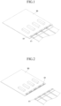
- FIG. 1 is a diagram illustrating a state in which the connector of the sensing electrical component and the inspection board are connected in an existing battery module.
- FIG. 2 is a diagram illustrating a state in which the connector of the sensing electrical component and the inspection board in FIG. 1 are separated.
- the connector of the sensing electrical component in the existing battery module is configured with a hook structure to prevent the connector from being separated due to vibration or impact in the field, or is configured with a device that is not easily loosened in such a way that the connector is press-fitted.
- An aspect of the present disclosure is directed to providing an automatic separation jig for a battery module capable of eliminating a source cause of defects during connector disassembly work in an inspection process for manufacturing a battery module, reducing production loss and cost by improving workability, and addressing safety issues caused by damage to electrical components of high-voltage products.
- An automatic separation jig for manufacturing a battery module includes: a button lever; and a guide holder to which the button lever is coupled and to guide a movement of the button lever, wherein a connector of the battery module coupled to a connector of an inspection board is separated by operating the button lever.
- buttons levers are spaced apart and disposed on the guide holder.
- the button lever includes a button unit; and a slide unit movably disposed on the guide holder.
- the slide unit extends in one direction from one side of the button unit.
- the slide unit is formed integrally with the button unit.
- the slide unit includes a connector pressing rib for pressing the connector of the battery module.
- the slide unit includes a hook pressing unit for pressing a hook of the connector of the battery module.
- the guide holder includes an insertion hole into which the slide unit is inserted and guides a movement of the slide unit.
- the plurality of the button levers are spaced apart and disposed on the guide holder, and the insertion hole is formed in a plural number so that each of the slide units is inserted into the insertion hole.
- the insertion hole is formed from one side surface of the guide holder to the other side surface opposite to the guide holder.
- the insertion hole has an inclined surface that is inclined downward at the bottom so that the slide unit moves forward and downward when sliding.
- the guide holder further includes an insertion groove on one side surface where the button unit is disposed.
- the insertion groove communicates with one end of the insertion hole.
- the automatic separation jig for manufacturing the battery module is disposed on the inspection board.
- a lower groove is formed in a lower portion of the guide holder, and the connector of the inspection board is located in the lower groove.
- the connector of the battery module is preferably a connector of a sensing unit in the battery module.
- a connector can be disassembled with a one-touch method even in a narrow space when a battery module is manufactured, thereby preventing losses and risks due to damage to electrical components.
- the connector of the battery module can be separated from the connector of the inspection board at once in a one-touch manner.
- the battery module 1 may include a plurality of battery cells 10, a module housing 20, and a plurality of busbars 30, and may further include a sensing unit 40 connected to the bus bar 30 and used to sense the voltage and temperature of each cell.
- the battery cells 10 may be cylindrical battery cells 10 in which an electrode assembly is embedded in a metal can.
- the cylindrical battery cell 10 may be configured to include a battery can 11 mainly made of a lightweight conductive metal material such as aluminum in a cylindrical shape, a jelly-roll type electrode assembly accommodated in the battery can 11, and a top cap coupled to an upper portion of the battery can 11.
- the top cap is connected to the positive electrode tab of the electrode assembly to function as a positive electrode terminal
- the battery can 11 is connected to the negative electrode tab of the electrode assembly to function as a negative electrode terminal.
- the cylindrical battery cell 10 may be inserted and disposed in the module housing 20, and the cylindrical battery cells 10 are bonded to the busbars 30 by wire in a predetermined pattern to be connected in series and/or in parallel to each other.
- the battery cells applied to the battery module 1 are not necessarily limited to the cylindrical battery cell 10.
- the battery module 1 according to an aspect of the present disclosure may be configured using a can-type battery cell having a rectangular parallelepiped shape or other shape, other than a cylindrical shape in the battery can 11.
- the module housing 20 is a structure for accommodating and fixing the battery cells 10 therein to protect the battery cells 10 from external impact or vibration, and may be configured to include a cell bottom frame 22 and a cell top frame 21.
- the cell bottom frame 22 may be configured to have cell insertion holes inside an outer rim in a rectangular box shape and to insert the battery cells 10 into the cell insertion holes one by one.
- the battery cells 10 may be inserted and disposed in each cell insertion hole such that the top cap faces upward and the lower region, that is, the bottom of the battery can 11 faces downward.
- the cell insertion hole is configured to penetrate the bottom surface of the cell bottom frame 22. Accordingly, the bottom of the battery can 11 of the battery cells 10 may be exposed below the bottom surface of the cell bottom frame 22.
- thermally conductive pad having insulation is attached to the bottom surface of the cell bottom frame 22 and a cooling plate or a heat sink (including a refrigerant therein) is attached to the other surface of the thermally conductive pad, thereby absorbing heat of the cylindrical battery cells 10.
- the cell bottom frame 22 may be firmly coupled to the cell top frame 21 by a long bolt (not shown) together with hook fastening.
- the cell top frame 21 may cover an upper region of the battery cells 10 and may be configured to be coupled to the cell bottom frame 22.
- the cell top frame 21 may have cell sockets (not shown) matching the cell insertion holes of the cell bottom frame 22 up and down.
- the battery cells 10 may be introduced into the cell sockets from the top cap so that an upper region of the entire battery cells 10 may be covered by the cell top frame 21.
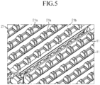
- the cell top frame 21 may include an upper surface portion covering the top of the entire battery cells 10 and four side portions forming a wall surrounding the outside of the entire battery cells 10 together with the cell bottom frame 22, wherein the upper surface portion of the cell top frame 21, as illustrated in FIG. 5 , has a plurality of holes 21a and seating grooves 21b.
- a side surface plate 23 may be coupled to a side surface portion of the cell top frame 21.
- the holes 21a have a configuration in which the cell top frame 21 is partially perforated so that the top cap of the battery cells 10 or an upper end of the battery can 11 is partially exposed to the outside.
- the cell bottom frame 22 when the battery cells 10 are inserted therein, may be configured such that the battery cells 10 form a plurality of rows in an X-axis or Y-axis direction of the module housing 20.
- the top cap of each battery cell 10 or an upper end of the battery can 11 is partially exposed to the outside.
- the holes 21a are used as paths for connecting the battery cells 10 located inside the module housing 20 to the busbars 30 located outside the module housing 20 by metal wires 500.
- the bus bar 30 may be connected to the top cap exposed through the holes 21a or an upper end of the battery can 11 by a metal wire.
- a wire bonding method in which one end of the metal wire is ultrasonically welded to the top cap or an upper end of the battery can 11 and the other end of the metal wire is ultrasonically welded to the bus bar 30 may be employed.
- the seating grooves 21b are places where the bus bar 30 is to be seated and fixed, and may extend along the lengthwise direction (Y-axis direction) of the module housing 20 to be provided at predetermined intervals in the widthwise direction (X-axis direction) of the module housing 20.
- the bus bar 30, which is a straight metal conductor having the same left and right widths, may be disposed in each of the seating grooves 21b.
- the bus bar 30 has approximately the same left and right widths as the seating groove 21b, so that its movement in the widthwise direction (X-axis direction) may be blocked.
- the bus bar 30 may be provided in the form of a pin or a pillar formed to protrude from the surface of the seating groove 21b (in an Z-axis direction), and may have a pin hole disposed into which the pin of the seating groove 21b is inserted into the bus bar 30. Accordingly, the pin of the seating groove 21b is inserted into the pin hole of the bus bar 30, thereby preventing movement thereof.
- the sensing unit 40 is an electrical component for sensing voltage, temperature, etc., and may include a sensing plate.
- the connector 41 of the sensing electrical component is configured with a hook structure to prevent the connector 41 from being separated due to vibration or impact in the field, or is configured with a device that is not easily loosened in such a way that the connector 41 is press-fitted.
- an aspect of the present disclosure is directed to providing an automatic separation jig 1000 for manufacturing the battery module to address an issue arising from connector release work, which is essential for EOL function inspection in the battery module manufacturing process.
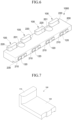
- FIG. 6 is a perspective view of an automatic separation jig according to an aspect of the present disclosure.
- FIG. 7 is a perspective view of a button lever in FIG. 6 .
- FIG. 8 is a bottom perspective view of the button lever illustrated in FIG. 7 .
- FIG. 9 is a diagram illustrating a state in which the automatic separation jig according to an aspect of the present disclosure is seated on the inspection board.
- FIG. 10 is a cross-sectional view showing a state in which the connector of a sensing unit is connected to the inspection board while the automatic separation jig according to an aspect of the present disclosure is seated on the inspection board.
- FIG. 10 is a cross-sectional view showing a state in which the connector of a sensing unit is connected to the inspection board while the automatic separation jig according to an aspect of the present disclosure is seated on the inspection board.
- FIG. 11 is a cross-sectional view showing a state in which the connector of the sensing unit is separated from the inspection board by the automatic separation jig according to an aspect of the present disclosure.
- FIG. 12 is a perspective view showing a state in which the connector of the sensing unit has been completely separated from the inspection board.
- the automatic separation jig 1000 for manufacturing the battery module according to an aspect of the present disclosure may include a plurality of the button levers 100 and a guide holder 200 to which the button levers 100 are coupled.
- the button lever 100 is a one-touch button lever 100 for separating the connector 41 of the sensing unit 40 from the inspection board 50 by one-touch operation, and may include a button unit 110 and a slide unit 120.
- the button unit 110 is used to move the slide unit 120 to release the coupling of the connector 41.
- the slide unit 120 may move to release the coupling of the connector 41.
- the plurality of the button units 110 may each be located in an insertion groove 220 of the guide holder 200.
- the slide unit 120 is used to release the coupling of the connector 41 from the inspection board 50 by manipulating the button unit 110.
- the slide unit 120 extends forward from a lower portion of the button unit 110, and is inserted into the insertion hole 210 of the guide holder 200. By manipulating the button unit 110, the slide unit 120 may slide into the insertion hole 210 to release the coupling of the connector 41.
- the slide unit 120 may include a connector pressing rib 121 and a hook pressing unit 122.
- the connector pressing rib 121 protrudes downward on both sides of the lower surface of the slide unit 120 and extends along the lengthwise direction.
- the slide unit 120 may serve to press the connector 41 when sliding within the insertion hole 210 of the guide holder 200.
- the hook pressing unit 122 protrudes downward from the front of the lower surface of the slide unit 120.
- the slide unit 120 may serve to press a hook 42 of the connector 41 when sliding within the insertion hole 210 of the guide holder 200.
- the slide unit 120 may be formed integrally with the button unit 110.
- the material of the button lever 100 may be made of synthetic resin in this aspect or may be made of other materials.
- buttons levers 100 are illustrated coupled to the guide holder 200, but the number of button levers 100 may be changed.
- the guide holder 200 is coupled to the button lever 100 and guides the movement of the button lever 100 according to the manipulation of the button unit 110, and may include the insertion hole 210 into which the slide unit 120 of the button lever 100 is inserted and the insertion groove 220 into which the button unit 110 of the button lever 100 is located.
- the insertion hole 210 of the guide holder 200 is a place where the slide unit 120 of the button lever 100 is inserted.
- Four insertion holes 210 may be formed to be spaced apart from each other in the lengthwise direction of the guide holder 200, equal to the number of button levers 100.
- the insertion hole 210 may be formed to penetrate from one side of the guide holder 200 to the other side, and the slide unit 120 of the button lever 100 may be inserted into one end of the insertion hole 210 and the end of the slide unit 120 may protrude to the other end of the insertion hole 210.
- the slide unit 120 of the button lever 100 may be seated at the bottom of the insertion hole 210, and the insertion hole 210 that guides the movement of the slide unit 120 may be formed to be inclined downward in a forward direction of the slide unit 120 with respect to the bottom of the guide holder 200.
- the bottom of the insertion hole 210 may have an inclined surface 211.
- the slide unit 120 moves along the inclined surface 211 that is inclined downward so that the slide unit 120 may also gradually move downward while moving forward.
- the insertion groove 220 of the guide holder 200 is a place where the button unit 110 of the button lever 100 is inserted.
- Four insertion grooves 220 may be formed to be spaced apart from each other in the lengthwise direction of the guide holder 200, equal to the number of button levers 100.
- the insertion groove 220 may be formed to be concave inward on one side of the guide holder 200, and the insertion groove 220 may communicate with one end of the insertion hole 210.
- the slide unit 120 of the button lever 100 may be inserted into the insertion hole 210 and the button unit 110 may be located within the insertion groove 220.
- the guide holder 200 may have a fastening hole 201.
- the fastening hole 201 is formed to penetrate the top and bottom of the guide holder 200 and is for fixing the guide holder 200 with a fixing bolt (not shown).
- the fixing bolt may be inserted into the fastening hole 201 and the inserted fixing bolt may be fastened to the inspection board 50, so that the automatic separation jig 1000 may be fixed to the inspection board 50.
- the automatic separation jig 1000 for manufacturing the battery module according to an aspect of the present disclosure is disposed on the inspection board 50 of the production line equipment.
- the automatic separation jig 1000 may be disposed on the inspection board 50 so that the connector 51 of the inspection board 50 is located in the lower groove 230 formed in the lower portion of the automatic separation jig 1000, and the automatic separation jig 1000 may be fixed to the inspection board 50 by fastening the fixing bolt inserted inside the fastening hole 201 to the inspection board 50.
- the connector 41 of the sensing unit 40 in the battery module 1 may be coupled to the connector 51 of the inspection board 50. Specifically, the hook 42 of the connector 41 in the sensing unit 40 may be caught and fixed to the connector 51 of the inspection board 50. Simultaneously, as illustrated in FIG. 10 , when the connector 41 of the sensing unit 40 is inserted into the connector 51 of the inspection board 50, the connector 41 of the sensing unit 40 pushes the button lever 100 so that the button lever 100 may be located in a correct position.
- each connector 41 of the sensing unit 40 may be separated from the connector 51 of the inspection board 50.
- an operator may press the button unit 110 of the button lever 100 with his or her finger in the direction of the arrow illustrated in FIG. 11 .
- the button lever 100 moves forward, and the slide unit 120 of the button lever 100 is guided to the insertion hole 210 of the guide holder 200 and moves forward.
- the slide unit 120 may move forward and gradually move downward by moving along the inclined surface 211 inclined downward and configuring the bottom of the insertion hole 210.
- the hook pressing unit 122 formed on the lower surface of the slide unit 120 presses the hook 42 of the connector 41, thereby releasing the fixation of the connector 41 of the sensing unit 40 and the connector 51 of the inspection board 50. Then, as the slide unit 120 moves forward, the slide unit 120 pushes the connector 41 of the sensing unit 40, so that the connector of the sensing unit may be completely separated from the connector 51 of the inspection board 50.
- FIG. 12 is a perspective view showing a state in which the connector of the sensing unit has been completely separated from the inspection board.
- the slide unit 120 of the button lever 100 presses the hook 42 of the connector 41, and the connector 41 is separated from the inspection board 50.
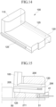
- FIG. 13 is a perspective view of an automatic separation jig according to another aspect of the present disclosure.
- FIG. 14 is a perspective view of the button lever in FIG. 13 .
- FIG. 15 is a cross-sectional view showing a state in which the connector of the sensing unit is connected to the inspection board while the automatic separation jig illustrated in FIG. 13 is seated on the inspection board.
- the automatic separation jig 1000 according to the second aspect of the present disclosure is different from that of the first aspect in that slide protrusions 125 are disposed on both side surfaces of the slide unit 120 of the button lever 100, and in the guide holder 200, guide grooves 205 into which the slide protrusions 125 are inserted are formed on both inner side surfaces of the insertion hole 210.
- the guide groove 205 is used to guide the slide movement of the slide protrusions 125 in which the slide protrusions 125 of the slide unit 120 are inserted.
- the guide groove 205 may also be formed to be inclined downward in the forward direction of the slide unit 120. Accordingly, the guide groove 205 may be formed parallel to the inclined surface 211 of the insertion hole 210.
- the guide grooves 205 may be formed on both side surfaces inside the insertion hole 210, respectively.
- a spring 206 may be disposed in an inner front portion of the guide groove 205 to elastically support the slide protrusion 125 of the slide unit 120.
- the spring 206 is used to elastically support the slide protrusion 125. As the slide unit 120 moves forward, the connector 41 of the sensing unit 40 is separated from the connector 51 of the inspection board 50. Then, the slide unit 120 may be returned to its original position by the restoring force of the spring 206.
- the slide protrusions 125 may be disposed on both side surfaces of the slide unit 120, and each slide protrusion 125 may be inserted into the guide groove 205 inside the insertion hole 210 of the guide holder 200, so that the slide protrusions 125 may be guided and moved in the guide groove 205 as the slide unit 120 moves.
- the slide unit 120 of the button lever 100 moves forward from the insertion hole 210 of the guide holder 200. Simultaneously, the slide protrusion 125 inserted into the guide groove 205 moves forward within the guide groove 205.
- the slide protrusion 125 moves along the downwardly inclined guide groove 205 so that the slide unit 120 may move forward and gradually move downward. Additionally, the slide protrusion 125 may compress the spring 206 while moving forward within the guide groove 205.
- the hook pressing unit 122 formed on the lower surface of the slide unit 120 presses the hook 42 of the connector 41, thereby releasing the fixation of the connector 41 of the sensing unit 40 and the connector 51 of the inspection board 50. Then, as the slide unit 120 moves forward, the slide unit 120 pushes the connector 41 of the sensing unit 40, so that the connector of the sensing unit may be completely separated from the connector 51 of the inspection board 50.
- the slide protrusion 125 returns to its original position by the restoring force of the compressed spring 206, and this allows the button lever 100 to return to its original position.
- the slide protrusions 125 are disposed on both side surfaces of the slide unit 120 of the button lever 100, and the slide protrusions 125 are inserted into the guide groove 205 in the insertion hole 210 and moved. Thereby, the slide unit 120 is not twisted to the left or right, straightness is improved, and the separation work on of the connector 41 may be performed more stably.
- the present disclosure provides a jig capable of automatically disconnecting the connection between a connector of a sensing electrical component of a battery module and an inspection board with one touch in a battery module manufacturing process.
Landscapes
- Chemical & Material Sciences (AREA)
- Chemical Kinetics & Catalysis (AREA)
- Electrochemistry (AREA)
- General Chemical & Material Sciences (AREA)
- Engineering & Computer Science (AREA)
- Manufacturing & Machinery (AREA)
- Battery Mounting, Suspending (AREA)
Abstract
Description
- The present disclosure relates to an automatic separation jig for manufacturing a battery module, and more specifically, to a jig capable of automatically disconnecting the connection between a connector of a sensing electrical component of a battery module and an inspection board with one touch in a battery module manufacturing process.
- A secondary battery means a battery capable of charging/discharging, unlike a non-rechargeable primary battery, and is applied not only to portable devices but also to electric vehicles (EV, Electric Vehicle) and hybrid vehicles (HEV, Hybrid Electric Vehicle) that are driven by an electric drive source.
- Currently, widely used secondary batteries include lithium ion batteries, lithium polymer batteries, nickel-cadmium batteries, nickel-hydrogen batteries, nickel-zinc batteries, and the like. The operating voltage of a unit secondary battery cell, i.e., a unit battery cell, is about 2.5V-4.2V. Accordingly, when higher output voltage is required, a plurality of battery cells may be connected in series to construct a battery pack. Additionally, according to the charge/discharge capacity required for the battery pack, a plurality of battery cells may be connected in parallel to construct a battery pack. Accordingly, the number of battery cells included in the battery pack may be variously set according to the required output voltage or charge/discharge capacity.
- When constructing a battery pack by connecting a plurality of battery cells in series/in parallel, it is common to first construct a battery module including at least one battery cell, preferably a plurality of battery cells, and then construct a battery pack using at least one such battery module with the addition of other components. Herein, the battery module refers to a component in which a plurality of battery cells are connected in series or in parallel, and the battery pack refers to a component in which a plurality of battery modules are connected in series or in parallel to increase the capacity and output.
- The battery module is configured with electrical components (FPCB, ICB) for sensing voltage, temperature, etc. In order to inspect a product in a battery module manufacturing process, it is necessary to assemble a connector of a sensing electrical component and an inspection board of production line equipment.
-
FIG. 1 is a diagram illustrating a state in which the connector of the sensing electrical component and the inspection board are connected in an existing battery module.FIG. 2 is a diagram illustrating a state in which the connector of the sensing electrical component and the inspection board inFIG. 1 are separated. - As illustrated, the connector of the sensing electrical component in the existing battery module is configured with a hook structure to prevent the connector from being separated due to vibration or impact in the field, or is configured with a device that is not easily loosened in such a way that the connector is press-fitted.
- Accordingly, in a production line, after the final EOL inspection of a product, it is difficult to disassemble the connector of the sensing electrical component from a
connector 51 of an inspection board. Issues arise due to the narrow space between the inspection board and the connector of the product, difficult connector disassembly work, and damage to physically weak electrical components. - An aspect of the present disclosure is directed to providing an automatic separation jig for a battery module capable of eliminating a source cause of defects during connector disassembly work in an inspection process for manufacturing a battery module, reducing production loss and cost by improving workability, and addressing safety issues caused by damage to electrical components of high-voltage products.
- An automatic separation jig for manufacturing a battery module according to an aspect of the present disclosure includes: a button lever; and a guide holder to which the button lever is coupled and to guide a movement of the button lever, wherein a connector of the battery module coupled to a connector of an inspection board is separated by operating the button lever.
- In addition, a plurality of the button levers are spaced apart and disposed on the guide holder.
- In addition, the button lever includes a button unit; and a slide unit movably disposed on the guide holder.
- In addition, the slide unit extends in one direction from one side of the button unit.
- In addition, the slide unit is formed integrally with the button unit.
- In addition, the slide unit includes a connector pressing rib for pressing the connector of the battery module.
- In addition, the slide unit includes a hook pressing unit for pressing a hook of the connector of the battery module.
- In addition, the guide holder includes an insertion hole into which the slide unit is inserted and guides a movement of the slide unit.
- In addition, the plurality of the button levers are spaced apart and disposed on the guide holder, and the insertion hole is formed in a plural number so that each of the slide units is inserted into the insertion hole.
- In addition, the insertion hole is formed from one side surface of the guide holder to the other side surface opposite to the guide holder.
- In addition, the insertion hole has an inclined surface that is inclined downward at the bottom so that the slide unit moves forward and downward when sliding.
- In addition, the guide holder further includes an insertion groove on one side surface where the button unit is disposed.
- In addition, the insertion groove communicates with one end of the insertion hole.
- In addition, the automatic separation jig for manufacturing the battery module is disposed on the inspection board.
- In addition, a lower groove is formed in a lower portion of the guide holder, and the connector of the inspection board is located in the lower groove.
- In addition, the connector of the battery module is preferably a connector of a sensing unit in the battery module.
- Accordingly, according to an aspect of the present disclosure, a connector can be disassembled with a one-touch method even in a narrow space when a battery module is manufactured, thereby preventing losses and risks due to damage to electrical components.
- In addition, according to an aspect of the present disclosure, the connector of the battery module can be separated from the connector of the inspection board at once in a one-touch manner.
-
-
FIG. 1 is a diagram illustrating a state in which a connector of a sensing electrical component of the existing battery module and an inspection board are connected. -
FIG. 2 is a diagram illustrating a state in which the connector of the sensing electrical component of a battery module and the inspection board inFIG. 1 are separated. -
FIG. 3 is a perspective view of the battery module. -
FIG. 4 is an exploded perspective view of the battery module ofFIG. 3 . -
FIG. 5 is a partial detailed view of a cell top frame inFIG. 3 . -
FIG. 6 is a perspective view of an automatic separation jig according to an aspect of the present disclosure. -
FIG. 7 is a perspective view of a button lever inFIG. 6 . -
FIG. 8 is a bottom perspective view of the button lever illustrated inFIG. 7 . -
FIG. 9 is a diagram illustrating a state in which the automatic separation jig according to an aspect of the present disclosure is seated on the inspection board. -
FIG. 10 is a cross-sectional view showing a state in which the connector of a sensing unit is connected to the inspection board while the automatic separation jig according to an aspect of the present disclosure is seated on the inspection board. -
FIG. 11 is a cross-sectional view showing a state in which the connector of the sensing unit is separated from the inspection board by the automatic separation jig according to an aspect of the present disclosure. -
FIG. 12 is a perspective view showing a state in which the connector of the sensing unit has been completely separated from the inspection board. -
FIG. 13 is a perspective view of an automatic separation jig according to another of the present disclosure. -
FIG. 14 is a perspective view of the button lever inFIG. 13 . -
FIG. 15 is a cross-sectional view showing a state in which the connector of the sensing unit is connected to the inspection board while the automatic separation jig illustrated inFIG. 13 is seated on the inspection board. - The advantages, features of the present disclosure, and methods for achieving the same will become apparent from the following description of aspects given in detail in conjunction with the accompanying drawings. However, the present disclosure is not limited to the aspects described herein but may be embodied in many different forms. Rather, the aspects disclosed herein are provided in order to ensure that the disclosure becomes thorough and perfect and to ensure that the scope of the present disclosure is sufficiently delivered to those skilled in the technical field to which the present disclosure pertains. The present disclosure is defined only by the claims. Accordingly, in some aspects, well-known process stages, well-known device structures, and well-known techniques are not specifically described in order to avoid ambiguous interpretation of the present disclosure. Like reference numerals refer to like elements throughout the specification.
- In the drawings, in order to clearly express a plurality of layers and regions, the thickness may be exaggerated. Like reference numerals refer to like portions throughout the specification. It will be understood that when an element such as a layer, film, region or substrate is referred to as being "on" another element, it may be directly on the other element or intervening elements may also be present. In contrast, when an element is referred to as being "directly on" another element, there are no intervening elements present. Further, it will also be understood that when an element such as a layer, film, region or substrate is referred to as being "below" another element, it may be directly below the other element, or intervening elements may also be present. In contrast, when an element is referred to as being "directly below" another element, there are no intervening elements present.
- Prior to the description of an
automatic separation jig 1000 for manufacturing a battery module according to an aspect of the present disclosure, the structure of a battery module 1 will be described with reference toFIGS. 3 to 5 as follows. - The battery module 1 may include a plurality of
battery cells 10, amodule housing 20, and a plurality ofbusbars 30, and may further include asensing unit 40 connected to thebus bar 30 and used to sense the voltage and temperature of each cell. - The
battery cells 10 may becylindrical battery cells 10 in which an electrode assembly is embedded in a metal can. Thecylindrical battery cell 10 may be configured to include a battery can 11 mainly made of a lightweight conductive metal material such as aluminum in a cylindrical shape, a jelly-roll type electrode assembly accommodated in the battery can 11, and a top cap coupled to an upper portion of the battery can 11. The top cap is connected to the positive electrode tab of the electrode assembly to function as a positive electrode terminal, and the battery can 11 is connected to the negative electrode tab of the electrode assembly to function as a negative electrode terminal. - The
cylindrical battery cell 10 may be inserted and disposed in themodule housing 20, and thecylindrical battery cells 10 are bonded to thebusbars 30 by wire in a predetermined pattern to be connected in series and/or in parallel to each other. - The battery cells applied to the battery module 1 are not necessarily limited to the
cylindrical battery cell 10. For example, the battery module 1 according to an aspect of the present disclosure may be configured using a can-type battery cell having a rectangular parallelepiped shape or other shape, other than a cylindrical shape in the battery can 11. - The
module housing 20 is a structure for accommodating and fixing thebattery cells 10 therein to protect thebattery cells 10 from external impact or vibration, and may be configured to include acell bottom frame 22 and acell top frame 21. - The
cell bottom frame 22 may be configured to have cell insertion holes inside an outer rim in a rectangular box shape and to insert thebattery cells 10 into the cell insertion holes one by one. For example, as shown inFIG. 4 , thebattery cells 10 may be inserted and disposed in each cell insertion hole such that the top cap faces upward and the lower region, that is, the bottom of the battery can 11 faces downward. Herein, the cell insertion hole is configured to penetrate the bottom surface of thecell bottom frame 22. Accordingly, the bottom of the battery can 11 of thebattery cells 10 may be exposed below the bottom surface of thecell bottom frame 22. Although not illustrated in the drawings, it may also be configured such that a thermally conductive pad having insulation is attached to the bottom surface of thecell bottom frame 22 and a cooling plate or a heat sink (including a refrigerant therein) is attached to the other surface of the thermally conductive pad, thereby absorbing heat of thecylindrical battery cells 10. - The
cell bottom frame 22 may be firmly coupled to thecell top frame 21 by a long bolt (not shown) together with hook fastening. - The
cell top frame 21 may cover an upper region of thebattery cells 10 and may be configured to be coupled to thecell bottom frame 22. - For example, the
cell top frame 21 may have cell sockets (not shown) matching the cell insertion holes of thecell bottom frame 22 up and down. When thecell top frame 21 and thecell bottom frame 22 are coupled, thebattery cells 10 may be introduced into the cell sockets from the top cap so that an upper region of theentire battery cells 10 may be covered by thecell top frame 21. - In addition, the
cell top frame 21 may include an upper surface portion covering the top of theentire battery cells 10 and four side portions forming a wall surrounding the outside of theentire battery cells 10 together with thecell bottom frame 22, wherein the upper surface portion of thecell top frame 21, as illustrated inFIG. 5 , has a plurality ofholes 21a andseating grooves 21b. Aside surface plate 23 may be coupled to a side surface portion of thecell top frame 21. - The
holes 21a have a configuration in which thecell top frame 21 is partially perforated so that the top cap of thebattery cells 10 or an upper end of the battery can 11 is partially exposed to the outside. - As illustrated in
FIG. 4 , thecell bottom frame 22, when thebattery cells 10 are inserted therein, may be configured such that thebattery cells 10 form a plurality of rows in an X-axis or Y-axis direction of themodule housing 20. Whensuch battery cells 10 are covered with thecell top frame 21, the top cap of eachbattery cell 10 or an upper end of the battery can 11 is partially exposed to the outside. - The
holes 21a are used as paths for connecting thebattery cells 10 located inside themodule housing 20 to thebusbars 30 located outside themodule housing 20 by metal wires 500. For example, thebus bar 30 may be connected to the top cap exposed through theholes 21a or an upper end of the battery can 11 by a metal wire. For example, a wire bonding method in which one end of the metal wire is ultrasonically welded to the top cap or an upper end of the battery can 11 and the other end of the metal wire is ultrasonically welded to thebus bar 30 may be employed. - The
seating grooves 21b are places where thebus bar 30 is to be seated and fixed, and may extend along the lengthwise direction (Y-axis direction) of themodule housing 20 to be provided at predetermined intervals in the widthwise direction (X-axis direction) of themodule housing 20. Thebus bar 30, which is a straight metal conductor having the same left and right widths, may be disposed in each of theseating grooves 21b. - The
bus bar 30 has approximately the same left and right widths as theseating groove 21b, so that its movement in the widthwise direction (X-axis direction) may be blocked. - In addition, the
bus bar 30 may be provided in the form of a pin or a pillar formed to protrude from the surface of theseating groove 21b (in an Z-axis direction), and may have a pin hole disposed into which the pin of theseating groove 21b is inserted into thebus bar 30. Accordingly, the pin of theseating groove 21b is inserted into the pin hole of thebus bar 30, thereby preventing movement thereof. - In the battery module 1, the
sensing unit 40 is an electrical component for sensing voltage, temperature, etc., and may include a sensing plate. - In order to inspect products in a battery module manufacturing process, it is necessary to assemble the
connector 41 of the sensing electrical component and theinspection board 50 of production line equipment. Theconnector 41 of the sensing electrical component is configured with a hook structure to prevent theconnector 41 from being separated due to vibration or impact in the field, or is configured with a device that is not easily loosened in such a way that theconnector 41 is press-fitted. - Accordingly, in a production line, after the final EOL inspection of a product, it is difficult to disassemble the
connector 41 of the sensing electrical component from aconnector 51 of aninspection board 50. Issues arise due to the narrow space between theinspection board 50 and theconnector 41 of the product, difficult connector disassembly work, and damage to physically weak electrical components. - In order to address an issue associated therewith, an aspect of the present disclosure is directed to providing an
automatic separation jig 1000 for manufacturing the battery module to address an issue arising from connector release work, which is essential for EOL function inspection in the battery module manufacturing process. -
FIG. 6 is a perspective view of an automatic separation jig according to an aspect of the present disclosure.FIG. 7 is a perspective view of a button lever inFIG. 6 .FIG. 8 is a bottom perspective view of the button lever illustrated inFIG. 7 .FIG. 9 is a diagram illustrating a state in which the automatic separation jig according to an aspect of the present disclosure is seated on the inspection board.FIG. 10 is a cross-sectional view showing a state in which the connector of a sensing unit is connected to the inspection board while the automatic separation jig according to an aspect of the present disclosure is seated on the inspection board.FIG. 11 is a cross-sectional view showing a state in which the connector of the sensing unit is separated from the inspection board by the automatic separation jig according to an aspect of the present disclosure.FIG. 12 is a perspective view showing a state in which the connector of the sensing unit has been completely separated from the inspection board. - The
automatic separation jig 1000 for manufacturing the battery module according to an aspect of the present disclosure may include a plurality of the button levers 100 and aguide holder 200 to which the button levers 100 are coupled. - The
button lever 100 is a one-touch button lever 100 for separating theconnector 41 of thesensing unit 40 from theinspection board 50 by one-touch operation, and may include abutton unit 110 and aslide unit 120. - The
button unit 110 is used to move theslide unit 120 to release the coupling of theconnector 41. When a user presses thebutton unit 110 with his or her finger in the direction of the arrow as illustrated inFIG. 11 , theslide unit 120 may move to release the coupling of theconnector 41. The plurality of thebutton units 110 may each be located in aninsertion groove 220 of theguide holder 200. - The
slide unit 120 is used to release the coupling of theconnector 41 from theinspection board 50 by manipulating thebutton unit 110. Theslide unit 120 extends forward from a lower portion of thebutton unit 110, and is inserted into theinsertion hole 210 of theguide holder 200. By manipulating thebutton unit 110, theslide unit 120 may slide into theinsertion hole 210 to release the coupling of theconnector 41. - The
slide unit 120 may include aconnector pressing rib 121 and ahook pressing unit 122. - As illustrated in
FIG. 8 , theconnector pressing rib 121 protrudes downward on both sides of the lower surface of theslide unit 120 and extends along the lengthwise direction. Theslide unit 120 may serve to press theconnector 41 when sliding within theinsertion hole 210 of theguide holder 200. - As illustrated in
FIG. 8 , thehook pressing unit 122 protrudes downward from the front of the lower surface of theslide unit 120. Theslide unit 120 may serve to press ahook 42 of theconnector 41 when sliding within theinsertion hole 210 of theguide holder 200. - The
slide unit 120 may be formed integrally with thebutton unit 110. - The material of the
button lever 100 may be made of synthetic resin in this aspect or may be made of other materials. - In this aspect, four
button levers 100 are illustrated coupled to theguide holder 200, but the number of button levers 100 may be changed. - The
guide holder 200 is coupled to thebutton lever 100 and guides the movement of thebutton lever 100 according to the manipulation of thebutton unit 110, and may include theinsertion hole 210 into which theslide unit 120 of thebutton lever 100 is inserted and theinsertion groove 220 into which thebutton unit 110 of thebutton lever 100 is located. - The
insertion hole 210 of theguide holder 200 is a place where theslide unit 120 of thebutton lever 100 is inserted. Four insertion holes 210 may be formed to be spaced apart from each other in the lengthwise direction of theguide holder 200, equal to the number of button levers 100. - As illustrated, the
insertion hole 210 may be formed to penetrate from one side of theguide holder 200 to the other side, and theslide unit 120 of thebutton lever 100 may be inserted into one end of theinsertion hole 210 and the end of theslide unit 120 may protrude to the other end of theinsertion hole 210. - Then, the
slide unit 120 of thebutton lever 100 may be seated at the bottom of theinsertion hole 210, and theinsertion hole 210 that guides the movement of theslide unit 120 may be formed to be inclined downward in a forward direction of theslide unit 120 with respect to the bottom of theguide holder 200. The bottom of theinsertion hole 210 may have aninclined surface 211. - Accordingly, when the
button lever 100 moves forward inside theinsertion hole 210, as illustrated inFIGS. 10 and 11 , theslide unit 120 moves along theinclined surface 211 that is inclined downward so that theslide unit 120 may also gradually move downward while moving forward. - The
insertion groove 220 of theguide holder 200 is a place where thebutton unit 110 of thebutton lever 100 is inserted. Fourinsertion grooves 220 may be formed to be spaced apart from each other in the lengthwise direction of theguide holder 200, equal to the number of button levers 100. - As illustrated, the
insertion groove 220 may be formed to be concave inward on one side of theguide holder 200, and theinsertion groove 220 may communicate with one end of theinsertion hole 210. - Accordingly, the
slide unit 120 of thebutton lever 100 may be inserted into theinsertion hole 210 and thebutton unit 110 may be located within theinsertion groove 220. - In addition, the
guide holder 200 may have afastening hole 201. As illustrated, thefastening hole 201 is formed to penetrate the top and bottom of theguide holder 200 and is for fixing theguide holder 200 with a fixing bolt (not shown). The fixing bolt may be inserted into thefastening hole 201 and the inserted fixing bolt may be fastened to theinspection board 50, so that theautomatic separation jig 1000 may be fixed to theinspection board 50. - Next, a method of operating the
automatic separation jig 1000 for manufacturing the battery module according to an aspect of the present disclosure having the configuration described above will be described. - First, the
automatic separation jig 1000 for manufacturing the battery module according to an aspect of the present disclosure is disposed on theinspection board 50 of the production line equipment. Specifically, as illustrated inFIG. 9 , theautomatic separation jig 1000 may be disposed on theinspection board 50 so that theconnector 51 of theinspection board 50 is located in thelower groove 230 formed in the lower portion of theautomatic separation jig 1000, and theautomatic separation jig 1000 may be fixed to theinspection board 50 by fastening the fixing bolt inserted inside thefastening hole 201 to theinspection board 50. - In addition, in order to inspect the battery module 1, the
connector 41 of thesensing unit 40 in the battery module 1 may be coupled to theconnector 51 of theinspection board 50. Specifically, thehook 42 of theconnector 41 in thesensing unit 40 may be caught and fixed to theconnector 51 of theinspection board 50. Simultaneously, as illustrated inFIG. 10 , when theconnector 41 of thesensing unit 40 is inserted into theconnector 51 of theinspection board 50, theconnector 41 of thesensing unit 40 pushes thebutton lever 100 so that thebutton lever 100 may be located in a correct position. - As such, after the final inspection is completed with the
connector 41 of thesensing unit 40 connected to theconnector 51 of theinspection board 50, eachconnector 41 of thesensing unit 40 may be separated from theconnector 51 of theinspection board 50. - When the
connector 41 of thesensing unit 40 and theconnector 51 of theinspection board 50 are separated, in theautomatic separation jig 1000, an operator may press thebutton unit 110 of thebutton lever 100 with his or her finger in the direction of the arrow illustrated inFIG. 11 . - Then, the
button lever 100 moves forward, and theslide unit 120 of thebutton lever 100 is guided to theinsertion hole 210 of theguide holder 200 and moves forward. Then, theslide unit 120 may move forward and gradually move downward by moving along theinclined surface 211 inclined downward and configuring the bottom of theinsertion hole 210. - As the
slide unit 120 gradually moves downward, thehook pressing unit 122 formed on the lower surface of theslide unit 120 presses thehook 42 of theconnector 41, thereby releasing the fixation of theconnector 41 of thesensing unit 40 and theconnector 51 of theinspection board 50. Then, as theslide unit 120 moves forward, theslide unit 120 pushes theconnector 41 of thesensing unit 40, so that the connector of the sensing unit may be completely separated from theconnector 51 of theinspection board 50. -
FIG. 12 is a perspective view showing a state in which the connector of the sensing unit has been completely separated from the inspection board. - Accordingly, in an aspect of the present disclosure, when an operator presses the
button unit 110 in a one-touch method as described above, theslide unit 120 of thebutton lever 100 presses thehook 42 of theconnector 41, and theconnector 41 is separated from theinspection board 50. Hence, it is possible to eliminate a source cause of defects during connector disassembly work in an inspection process for manufacturing a battery module, address safety issues caused by damage to electrical components, and reduce production loss and cost by improving workability. - Next, the automatic separation jig according to a second aspect of the present disclosure will be described.
FIG. 13 is a perspective view of an automatic separation jig according to another aspect of the present disclosure.FIG. 14 is a perspective view of the button lever inFIG. 13 .FIG. 15 is a cross-sectional view showing a state in which the connector of the sensing unit is connected to the inspection board while the automatic separation jig illustrated inFIG. 13 is seated on the inspection board. - The
automatic separation jig 1000 according to the second aspect of the present disclosure is different from that of the first aspect in thatslide protrusions 125 are disposed on both side surfaces of theslide unit 120 of thebutton lever 100, and in theguide holder 200, guidegrooves 205 into which theslide protrusions 125 are inserted are formed on both inner side surfaces of theinsertion hole 210. - The
guide groove 205 is used to guide the slide movement of theslide protrusions 125 in which theslide protrusions 125 of theslide unit 120 are inserted. Like theinsertion hole 210 that is formed to be inclined downward in the forward direction of theslide unit 120, theguide groove 205 may also be formed to be inclined downward in the forward direction of theslide unit 120. Accordingly, theguide groove 205 may be formed parallel to theinclined surface 211 of theinsertion hole 210. Theguide grooves 205 may be formed on both side surfaces inside theinsertion hole 210, respectively. - In addition, a
spring 206 may be disposed in an inner front portion of theguide groove 205 to elastically support theslide protrusion 125 of theslide unit 120. - The
spring 206 is used to elastically support theslide protrusion 125. As theslide unit 120 moves forward, theconnector 41 of thesensing unit 40 is separated from theconnector 51 of theinspection board 50. Then, theslide unit 120 may be returned to its original position by the restoring force of thespring 206. - The slide protrusions 125 may be disposed on both side surfaces of the
slide unit 120, and eachslide protrusion 125 may be inserted into theguide groove 205 inside theinsertion hole 210 of theguide holder 200, so that theslide protrusions 125 may be guided and moved in theguide groove 205 as theslide unit 120 moves. - In the
automatic separation jig 1000 according to the second aspect of the present disclosure, when theconnector 41 of thesensing unit 40 and theconnector 51 of theinspection board 50 are separated, as thebutton lever 100 moves forward, theslide unit 120 of thebutton lever 100 moves forward from theinsertion hole 210 of theguide holder 200. Simultaneously, theslide protrusion 125 inserted into theguide groove 205 moves forward within theguide groove 205. - Then, the
slide protrusion 125 moves along the downwardlyinclined guide groove 205 so that theslide unit 120 may move forward and gradually move downward. Additionally, theslide protrusion 125 may compress thespring 206 while moving forward within theguide groove 205. - As the
slide unit 120 gradually moves downward, thehook pressing unit 122 formed on the lower surface of theslide unit 120 presses thehook 42 of theconnector 41, thereby releasing the fixation of theconnector 41 of thesensing unit 40 and theconnector 51 of theinspection board 50. Then, as theslide unit 120 moves forward, theslide unit 120 pushes theconnector 41 of thesensing unit 40, so that the connector of the sensing unit may be completely separated from theconnector 51 of theinspection board 50. - Then, when the pressing of the
button unit 110 is released by an operator, theslide protrusion 125 returns to its original position by the restoring force of thecompressed spring 206, and this allows thebutton lever 100 to return to its original position. - In the
automatic separation jig 1000 according to the second aspect of the present disclosure, theslide protrusions 125 are disposed on both side surfaces of theslide unit 120 of thebutton lever 100, and theslide protrusions 125 are inserted into theguide groove 205 in theinsertion hole 210 and moved. Thereby, theslide unit 120 is not twisted to the left or right, straightness is improved, and the separation work on of theconnector 41 may be performed more stably. - Although the present disclosure has been described above with reference to preferred aspects, it is not limited to the aforementioned aspects. It will be understood by those skilled in the art to which the present disclosure pertains that various modifications and changes may be made to the present disclosure without departing from the spirit of the present disclosure.
- The present disclosure provides a jig capable of automatically disconnecting the connection between a connector of a sensing electrical component of a battery module and an inspection board with one touch in a battery module manufacturing process.
Claims (20)
- An automatic separation jig for manufacturing a battery module, comprising:a button lever; anda guide holder configured to guide a movement of the button lever,wherein the button lever is coupled to the guide holder, andwherein a connector of the battery module coupled to a connector of an inspection board is separated by the button lever.
- The automatic separation jig of claim 1, wherein a plurality of the button levers are spaced apart and disposed on the guide holder.
- The automatic separation jig of claim 1, wherein the button lever comprises:a button unit; anda slide unit configured to be movably disposed on the guide holder.
- The automatic separation jig of claim 3, wherein the slide unit extends in one direction from one side of the button unit.
- The automatic separation jig of claim 3, wherein the slide unit is formed integrally with the button unit.
- The automatic separation jig of claim 3, wherein the slide unit comprises a connector pressing rib configured to press the connector of the battery module.
- The automatic separation jig of claim 3, wherein the slide unit comprises a hook pressing unit configured to press a hook of the connector of the battery module.
- The automatic separation jig of claim 3, wherein the guide holder comprises an insertion hole into which the slide unit is inserted, and which is configured to guide a movement of the slide unit.
- The automatic separation jig of claim 8, wherein:a plurality of the button levers are spaced apart and disposed on the guide holder; andthe insertion hole is formed in a plural number so that each of the slide units is inserted into a respective insertion hole.
- The automatic separation jig of claim 8, wherein the insertion hole is formed from one side surface of the guide holder to an opposite side surface of the guide holder.
- The automatic separation jig of claim 8, wherein the insertion hole has an inclined surface that is inclined downward so that the slide unit is configured to move forward and downward when sliding.
- The automatic separation jig of claim 8, wherein the guide holder further includes an insertion groove on one side surface where the button unit is disposed.
- The automatic separation jig of claim 12, wherein the insertion groove communicates with one end of the insertion hole.
- The automatic separation jig of claim 1, wherein the automatic separation jig is disposed on the inspection board.
- The automatic separation jig of claim 1, wherein:the guide holder comprises a lower groove in a lower portion thereof; andthe connector of the inspection board is located in the lower groove.
- The automatic separation jig of claim 1, wherein the connector of the battery module is a connector of a sensing unit in the battery module.
- The automatic separation jig of claim 3, wherein:the button lever further comprises a slide protrusion disposed on the slide unit; andthe guide holder comprises a guide groove into which the slide protrusion is inserted and which is configured to guide a movement of the slide protrusion.
- The automatic separation jig of claim 17, wherein the guide holder further comprises a spring disposed in the guide groove so as to elastically support the slide protrusion.
- The automatic separation jig of claim 17, wherein the guide groove is formed to be inclined downward in a forward direction of the slide unit.
- The automatic separation jig of claim 17, wherein:the guide holder further comprises an insertion hole into which the slide unit is inserted and which is configured to guide a movement of the slide unit; andthe guide groove is disposed in the insertion hole.
Applications Claiming Priority (2)
| Application Number | Priority Date | Filing Date | Title |
|---|---|---|---|
| KR1020230063155A KR102876898B1 (en) | 2023-05-16 | 2023-05-16 | Automatic disconnection jig for manufacturing battery modules |
| PCT/KR2024/001203 WO2024237425A1 (en) | 2023-05-16 | 2024-01-25 | Automatic separation jig for manufacturing battery module |
Publications (2)
| Publication Number | Publication Date |
|---|---|
| EP4492522A1 true EP4492522A1 (en) | 2025-01-15 |
| EP4492522A4 EP4492522A4 (en) | 2025-10-29 |
Family
ID=93519183
Family Applications (1)
| Application Number | Title | Priority Date | Filing Date |
|---|---|---|---|
| EP24777203.1A Pending EP4492522A4 (en) | 2023-05-16 | 2024-01-25 | AUTOMATIC CUTTING DEVICE FOR THE MANUFACTURING OF A BATTERY MODULE |
Country Status (5)
| Country | Link |
|---|---|
| EP (1) | EP4492522A4 (en) |
| JP (1) | JP7776662B2 (en) |
| KR (1) | KR102876898B1 (en) |
| CN (1) | CN119325660A (en) |
| WO (1) | WO2024237425A1 (en) |
Family Cites Families (8)
| Publication number | Priority date | Publication date | Assignee | Title |
|---|---|---|---|---|
| JPH08315907A (en) * | 1995-05-18 | 1996-11-29 | Sumitomo Wiring Syst Ltd | Lever type connector |
| US6428341B2 (en) * | 2000-03-10 | 2002-08-06 | Yazaki Corporation | Inspecting jig for wire harness |
| KR20100011826A (en) * | 2008-07-25 | 2010-02-03 | 한국단자공업 주식회사 | Connector assembly having rework device |
| KR20140002846A (en) * | 2012-06-26 | 2014-01-09 | 삼성에스디아이 주식회사 | Battery module and testing method thereof |
| KR101348193B1 (en) * | 2012-07-30 | 2014-01-23 | 주식회사 유라코퍼레이션 | Multi type rework device |
| KR101720614B1 (en) * | 2013-08-30 | 2017-03-28 | 삼성에스디아이 주식회사 | Battery pack |
| KR101969320B1 (en) * | 2017-07-13 | 2019-04-17 | 주식회사 티피엠에스 | Batterty jig box for charging and discharging inspection, and testing apparatus using the same |
| KR102383403B1 (en) * | 2021-09-17 | 2022-04-25 | 주식회사 원익피앤이 | Jig for battery charging and discharging test |
-
2023
- 2023-05-16 KR KR1020230063155A patent/KR102876898B1/en active Active
-
2024
- 2024-01-25 EP EP24777203.1A patent/EP4492522A4/en active Pending
- 2024-01-25 JP JP2024544925A patent/JP7776662B2/en active Active
- 2024-01-25 WO PCT/KR2024/001203 patent/WO2024237425A1/en not_active Ceased
- 2024-01-25 CN CN202480002619.8A patent/CN119325660A/en active Pending
Also Published As
| Publication number | Publication date |
|---|---|
| EP4492522A4 (en) | 2025-10-29 |
| KR20240165693A (en) | 2024-11-25 |
| JP7776662B2 (en) | 2025-11-26 |
| CN119325660A (en) | 2025-01-17 |
| JP2025519309A (en) | 2025-06-26 |
| KR102876898B1 (en) | 2025-10-24 |
| WO2024237425A1 (en) | 2024-11-21 |
Similar Documents
| Publication | Publication Date | Title |
|---|---|---|
| JP7303270B2 (en) | battery pack | |
| KR102150679B1 (en) | Battery module, battery pack comprising the battery module and vehicle comprising the battery pack | |
| US9893333B2 (en) | Battery block and secondary battery module | |
| KR102082903B1 (en) | Battery module, battery pack comprising the battery module and vehicle comprising the battery pack | |
| JP5394522B2 (en) | Separating type connecting member for manufacturing secondary battery module and method for improving battery module performance by voltage leveling | |
| KR101126889B1 (en) | Battery pack | |
| US11349181B2 (en) | Battery module including insert-injection molded busbar assembly | |
| US10008709B2 (en) | Bus bar module, battery monitoring module, and battery module | |
| EP3605646B1 (en) | Battery pack having bottom connection type tray and method of manufacturing the same. | |
| JP2015050186A (en) | Battery pack | |
| KR102937234B1 (en) | Battery module, battery pack and energy storage system comprising the battery module | |
| KR20180124090A (en) | Battery and battery manufacturing method | |
| KR102093944B1 (en) | Battery module, battery pack comprising the battery module and vehicle comprising the battery pack | |
| KR101957403B1 (en) | Cell Lead Connecting Apparatus and Battery module including the same | |
| JP7776662B2 (en) | Automatic separation jig for battery module manufacturing | |
| KR102845496B1 (en) | battery pack | |
| EP4507109A1 (en) | Automatic busbar assembly jig, and battery module manufacturing method using same | |
| JP2024129792A (en) | Battery pack | |
| KR102840910B1 (en) | No-welding Inserting Type Battery Pack and Method for manufacturing the same | |
| KR102834586B1 (en) | Bus bar assembly and method for manufacturing thereof | |
| US20240213627A1 (en) | Battery-cell coupling structure | |
| EP4611168A1 (en) | Battery module and battery pack comprising same | |
| KR102754501B1 (en) | Battery module | |
| KR20260028264A (en) | Battery pack | |
| KR20260033720A (en) | Battery module and battery pack and vehicle including the same |
Legal Events
| Date | Code | Title | Description |
|---|---|---|---|
| STAA | Information on the status of an ep patent application or granted ep patent |
Free format text: STATUS: UNKNOWN |
|
| STAA | Information on the status of an ep patent application or granted ep patent |
Free format text: STATUS: THE INTERNATIONAL PUBLICATION HAS BEEN MADE |
|
| PUAI | Public reference made under article 153(3) epc to a published international application that has entered the european phase |
Free format text: ORIGINAL CODE: 0009012 |
|
| STAA | Information on the status of an ep patent application or granted ep patent |
Free format text: STATUS: REQUEST FOR EXAMINATION WAS MADE |
|
| 17P | Request for examination filed |
Effective date: 20241004 |
|
| AK | Designated contracting states |
Kind code of ref document: A1 Designated state(s): AL AT BE BG CH CY CZ DE DK EE ES FI FR GB GR HR HU IE IS IT LI LT LU LV MC ME MK MT NL NO PL PT RO RS SE SI SK SM TR |
|
| A4 | Supplementary search report drawn up and despatched |
Effective date: 20250926 |
|
| RIC1 | Information provided on ipc code assigned before grant |
Ipc: H01M 10/04 20060101AFI20250922BHEP Ipc: H01M 50/296 20210101ALI20250922BHEP Ipc: H01M 10/42 20060101ALI20250922BHEP Ipc: H01R 13/635 20060101ALI20250922BHEP Ipc: H01R 43/26 20060101ALI20250922BHEP |