EP4492517A2 - Battery cell and method of manufacturing battery cell - Google Patents
Battery cell and method of manufacturing battery cell Download PDFInfo
- Publication number
- EP4492517A2 EP4492517A2 EP24185009.8A EP24185009A EP4492517A2 EP 4492517 A2 EP4492517 A2 EP 4492517A2 EP 24185009 A EP24185009 A EP 24185009A EP 4492517 A2 EP4492517 A2 EP 4492517A2
- Authority
- EP
- European Patent Office
- Prior art keywords
- resin
- stacking direction
- pouch
- battery cell
- current collector
- Prior art date
- Legal status (The legal status is an assumption and is not a legal conclusion. Google has not performed a legal analysis and makes no representation as to the accuracy of the status listed.)
- Granted
Links
Images





Classifications
-
- H—ELECTRICITY
- H01—ELECTRIC ELEMENTS
- H01M—PROCESSES OR MEANS, e.g. BATTERIES, FOR THE DIRECT CONVERSION OF CHEMICAL ENERGY INTO ELECTRICAL ENERGY
- H01M10/00—Secondary cells; Manufacture thereof
- H01M10/04—Construction or manufacture in general
- H01M10/0413—Large-sized flat cells or batteries for motive or stationary systems with plate-like electrodes
-
- H—ELECTRICITY
- H01—ELECTRIC ELEMENTS
- H01M—PROCESSES OR MEANS, e.g. BATTERIES, FOR THE DIRECT CONVERSION OF CHEMICAL ENERGY INTO ELECTRICAL ENERGY
- H01M10/00—Secondary cells; Manufacture thereof
- H01M10/05—Accumulators with non-aqueous electrolyte
- H01M10/052—Li-accumulators
- H01M10/0525—Rocking-chair batteries, i.e. batteries with lithium insertion or intercalation in both electrodes; Lithium-ion batteries
-
- H—ELECTRICITY
- H01—ELECTRIC ELEMENTS
- H01M—PROCESSES OR MEANS, e.g. BATTERIES, FOR THE DIRECT CONVERSION OF CHEMICAL ENERGY INTO ELECTRICAL ENERGY
- H01M10/00—Secondary cells; Manufacture thereof
- H01M10/05—Accumulators with non-aqueous electrolyte
- H01M10/058—Construction or manufacture
- H01M10/0585—Construction or manufacture of accumulators having only flat construction elements, i.e. flat positive electrodes, flat negative electrodes and flat separators
-
- H—ELECTRICITY
- H01—ELECTRIC ELEMENTS
- H01M—PROCESSES OR MEANS, e.g. BATTERIES, FOR THE DIRECT CONVERSION OF CHEMICAL ENERGY INTO ELECTRICAL ENERGY
- H01M50/00—Constructional details or processes of manufacture of the non-active parts of electrochemical cells other than fuel cells, e.g. hybrid cells
- H01M50/10—Primary casings; Jackets or wrappings
- H01M50/102—Primary casings; Jackets or wrappings characterised by their shape or physical structure
- H01M50/105—Pouches or flexible bags
-
- H—ELECTRICITY
- H01—ELECTRIC ELEMENTS
- H01M—PROCESSES OR MEANS, e.g. BATTERIES, FOR THE DIRECT CONVERSION OF CHEMICAL ENERGY INTO ELECTRICAL ENERGY
- H01M50/00—Constructional details or processes of manufacture of the non-active parts of electrochemical cells other than fuel cells, e.g. hybrid cells
- H01M50/10—Primary casings; Jackets or wrappings
- H01M50/116—Primary casings; Jackets or wrappings characterised by the material
- H01M50/121—Organic material
-
- H—ELECTRICITY
- H01—ELECTRIC ELEMENTS
- H01M—PROCESSES OR MEANS, e.g. BATTERIES, FOR THE DIRECT CONVERSION OF CHEMICAL ENERGY INTO ELECTRICAL ENERGY
- H01M50/00—Constructional details or processes of manufacture of the non-active parts of electrochemical cells other than fuel cells, e.g. hybrid cells
- H01M50/10—Primary casings; Jackets or wrappings
- H01M50/116—Primary casings; Jackets or wrappings characterised by the material
- H01M50/124—Primary casings; Jackets or wrappings characterised by the material having a layered structure
-
- H—ELECTRICITY
- H01—ELECTRIC ELEMENTS
- H01M—PROCESSES OR MEANS, e.g. BATTERIES, FOR THE DIRECT CONVERSION OF CHEMICAL ENERGY INTO ELECTRICAL ENERGY
- H01M50/00—Constructional details or processes of manufacture of the non-active parts of electrochemical cells other than fuel cells, e.g. hybrid cells
- H01M50/10—Primary casings; Jackets or wrappings
- H01M50/131—Primary casings; Jackets or wrappings characterised by physical properties, e.g. gas permeability, size or heat resistance
- H01M50/136—Flexibility or foldability
-
- H—ELECTRICITY
- H01—ELECTRIC ELEMENTS
- H01M—PROCESSES OR MEANS, e.g. BATTERIES, FOR THE DIRECT CONVERSION OF CHEMICAL ENERGY INTO ELECTRICAL ENERGY
- H01M50/00—Constructional details or processes of manufacture of the non-active parts of electrochemical cells other than fuel cells, e.g. hybrid cells
- H01M50/10—Primary casings; Jackets or wrappings
- H01M50/172—Arrangements of electric connectors penetrating the casing
- H01M50/174—Arrangements of electric connectors penetrating the casing adapted for the shape of the cells
- H01M50/178—Arrangements of electric connectors penetrating the casing adapted for the shape of the cells for pouch or flexible bag cells
-
- H—ELECTRICITY
- H01—ELECTRIC ELEMENTS
- H01M—PROCESSES OR MEANS, e.g. BATTERIES, FOR THE DIRECT CONVERSION OF CHEMICAL ENERGY INTO ELECTRICAL ENERGY
- H01M50/00—Constructional details or processes of manufacture of the non-active parts of electrochemical cells other than fuel cells, e.g. hybrid cells
- H01M50/10—Primary casings; Jackets or wrappings
- H01M50/183—Sealing members
- H01M50/184—Sealing members characterised by their shape or structure
-
- H—ELECTRICITY
- H01—ELECTRIC ELEMENTS
- H01M—PROCESSES OR MEANS, e.g. BATTERIES, FOR THE DIRECT CONVERSION OF CHEMICAL ENERGY INTO ELECTRICAL ENERGY
- H01M50/00—Constructional details or processes of manufacture of the non-active parts of electrochemical cells other than fuel cells, e.g. hybrid cells
- H01M50/10—Primary casings; Jackets or wrappings
- H01M50/183—Sealing members
- H01M50/186—Sealing members characterised by the disposition of the sealing members
-
- H—ELECTRICITY
- H01—ELECTRIC ELEMENTS
- H01M—PROCESSES OR MEANS, e.g. BATTERIES, FOR THE DIRECT CONVERSION OF CHEMICAL ENERGY INTO ELECTRICAL ENERGY
- H01M50/00—Constructional details or processes of manufacture of the non-active parts of electrochemical cells other than fuel cells, e.g. hybrid cells
- H01M50/10—Primary casings; Jackets or wrappings
- H01M50/183—Sealing members
- H01M50/19—Sealing members characterised by the material
- H01M50/193—Organic material
-
- H—ELECTRICITY
- H01—ELECTRIC ELEMENTS
- H01M—PROCESSES OR MEANS, e.g. BATTERIES, FOR THE DIRECT CONVERSION OF CHEMICAL ENERGY INTO ELECTRICAL ENERGY
- H01M50/00—Constructional details or processes of manufacture of the non-active parts of electrochemical cells other than fuel cells, e.g. hybrid cells
- H01M50/50—Current conducting connections for cells or batteries
- H01M50/543—Terminals
- H01M50/547—Terminals characterised by the disposition of the terminals on the cells
- H01M50/55—Terminals characterised by the disposition of the terminals on the cells on the same side of the cell
-
- H—ELECTRICITY
- H01—ELECTRIC ELEMENTS
- H01M—PROCESSES OR MEANS, e.g. BATTERIES, FOR THE DIRECT CONVERSION OF CHEMICAL ENERGY INTO ELECTRICAL ENERGY
- H01M50/00—Constructional details or processes of manufacture of the non-active parts of electrochemical cells other than fuel cells, e.g. hybrid cells
- H01M50/50—Current conducting connections for cells or batteries
- H01M50/543—Terminals
- H01M50/552—Terminals characterised by their shape
- H01M50/553—Terminals adapted for prismatic, pouch or rectangular cells
-
- H—ELECTRICITY
- H01—ELECTRIC ELEMENTS
- H01M—PROCESSES OR MEANS, e.g. BATTERIES, FOR THE DIRECT CONVERSION OF CHEMICAL ENERGY INTO ELECTRICAL ENERGY
- H01M50/00—Constructional details or processes of manufacture of the non-active parts of electrochemical cells other than fuel cells, e.g. hybrid cells
- H01M50/50—Current conducting connections for cells or batteries
- H01M50/543—Terminals
- H01M50/552—Terminals characterised by their shape
- H01M50/553—Terminals adapted for prismatic, pouch or rectangular cells
- H01M50/557—Plate-shaped terminals
-
- H—ELECTRICITY
- H01—ELECTRIC ELEMENTS
- H01M—PROCESSES OR MEANS, e.g. BATTERIES, FOR THE DIRECT CONVERSION OF CHEMICAL ENERGY INTO ELECTRICAL ENERGY
- H01M2220/00—Batteries for particular applications
- H01M2220/20—Batteries in motive systems, e.g. vehicle, ship, plane
-
- Y—GENERAL TAGGING OF NEW TECHNOLOGICAL DEVELOPMENTS; GENERAL TAGGING OF CROSS-SECTIONAL TECHNOLOGIES SPANNING OVER SEVERAL SECTIONS OF THE IPC; TECHNICAL SUBJECTS COVERED BY FORMER USPC CROSS-REFERENCE ART COLLECTIONS [XRACs] AND DIGESTS
- Y02—TECHNOLOGIES OR APPLICATIONS FOR MITIGATION OR ADAPTATION AGAINST CLIMATE CHANGE
- Y02E—REDUCTION OF GREENHOUSE GAS [GHG] EMISSIONS, RELATED TO ENERGY GENERATION, TRANSMISSION OR DISTRIBUTION
- Y02E60/00—Enabling technologies; Technologies with a potential or indirect contribution to GHG emissions mitigation
- Y02E60/10—Energy storage using batteries
-
- Y—GENERAL TAGGING OF NEW TECHNOLOGICAL DEVELOPMENTS; GENERAL TAGGING OF CROSS-SECTIONAL TECHNOLOGIES SPANNING OVER SEVERAL SECTIONS OF THE IPC; TECHNICAL SUBJECTS COVERED BY FORMER USPC CROSS-REFERENCE ART COLLECTIONS [XRACs] AND DIGESTS
- Y02—TECHNOLOGIES OR APPLICATIONS FOR MITIGATION OR ADAPTATION AGAINST CLIMATE CHANGE
- Y02P—CLIMATE CHANGE MITIGATION TECHNOLOGIES IN THE PRODUCTION OR PROCESSING OF GOODS
- Y02P70/00—Climate change mitigation technologies in the production process for final industrial or consumer products
- Y02P70/50—Manufacturing or production processes characterised by the final manufactured product
Definitions
- the present invention relates to a battery cell and a method of manufacturing a battery cell.
- a conventional laminated battery is disclosed in Patent Literature 1.
- the conventional laminated battery is a battery in which an electrode body is accommodated in an exterior member.
- the conventional laminated battery includes plural current-collecting terminals that are drawn from the electrode body to the outside of the exterior member.
- the plural current-collecting terminals are superimposed on each other with a thermoplastic resin being interposed between two each of the plural current-collecting terminals.
- a peripheral edge portion of the exterior member is closed by welding the thermoplastic resin to the peripheral edge portion of the exterior member.
- each of the plural current-collecting terminals is drawn to the outside of the exterior member, and the plural current-collecting terminals are not connected to each other in the exterior member.
- a space inside the exterior member can be used to enlarge the electrode body, which is advantageous for improving energy density of the battery.
- the conventional laminated battery is manufactured by a heat-sealing process.
- the thermoplastic resins superimposed on each other in the peripheral edge portion of the exterior member are welded to each other by pressing a heat plate as an energy supply source against the thermoplastic resins in a superimposed direction.
- a battery cell includes:
- each of the plural stacked current collectors projects to the outside of the pouch through the opening of the pouch.
- the plural current collectors are connected to the electrodes with the same polarity, for example.
- the plural current collectors are not mutually connected.
- a space for connecting the current collectors in the pouch can be eliminated.
- the electrodes of the battery cell can be enlarged by using the space in the pouch. In this way, energy density of the battery cell can be increased.
- the opening of the pouch is sealed by the first resin and the second resin.
- the first resin and the second resin are supplied with energy for welding during manufacturing of the battery cell.
- Each of the first resin and the second resin is a thermoplastic resin, for example.
- the energy supplied to the first resin and the second resin is thermal energy, for example.
- the energy for welding is not limited to the thermal energy.
- the energy may be vibration energy, for example.
- An interface between the first resin and the second resin, each of which is supplied with the vibration energy, is welded by frictional heat.
- the current collectors, the first resin, and the second resin are stacked in the stacking direction.
- An energy supply source such as a heat plate, is located on the outer side in the stacking direction and supplies the energy from the outer side toward the center. The energy is transferred to the second resin through the current collectors and the first resin. Due to attenuation of the energy, the energy supplied to the second resin, which is located at the center in the stacking direction, is lower than the energy supplied to the first resin, which is located on the outer side in the stacking direction.
- the second resin is thinner than the first resin in the stacking direction.
- the supply energy per unit volume to the second resin is equivalent to the supply energy per unit volume to the first resin. Since the energy commensurate with the volume is supplied to the second resin, the second resin can sufficiently be welded to the current collector or another resin. Since the energy commensurate with the volume is also supplied to the first resin, the first resin can also sufficiently be welded to the current collector or another resin. In this way, it is possible to suppress insufficient welding of the resin during manufacturing of the battery cell.
- the battery cell may further include a third resin that seals the opening of the pouch, the third resin being welded to the current collector at a position between the stacked current collectors, being located between the first resin and the second resin in the stacking direction, being thinner than the first resin in the stacking direction, and being thicker than the second resin in the stacking direction.
- the third resin is located between the first resin and the second resin in the stacking direction.
- the energy for welding is transferred in an order of the first resin, the third resin, and the second resin.
- the thickness of the third resin in the stacking direction is less than the thickness of the first resin and greater than the thickness of the second resin.
- the supply energy per unit volume to the third resin is equivalent to the supply energy per unit volume to the second resin or the supply energy per unit volume to the first resin. Since the energy commensurate with the volume is supplied to the first resin, the second resin, and the third resin, each of the first resin, the second resin, and the third resin can stably and sufficiently be welded to the current collector or another resin.
- Portions of the current collectors, to which the first resin and the second resin are welded, may be thicker than the other portions thereof in the stacking direction.
- the current collector that is made of metal has higher energy transfer efficiency for welding than the resin, and examples of the energy are thermal energy and vibration energy.
- the metallic current collector has lower specific heat than the resin.
- the metallic current collector has higher Young's modulus than the resin.
- the current collector transfers the energy for welding relatively easily. In the case where the portion of the current collector, to which the resin is welded, is thick, the thickness of the resin is reduced. As a result, attenuation of the energy is suppressed during the energy transfer for welding in the stacking direction. The suppression of the energy attenuation is advantageous for the energy supply to the second resin at the center.
- the second resin may have a lower melting point than the first resin.
- the second resin has the low melting point
- the second resin can be welded to the current collector or another resin even with the low supply energy to the second resin.
- the second resin with the low melting point can suppress insufficient welding of the resin.
- a battery cell includes:
- the second resin has the low melting point
- the second resin can be welded even with the low supply energy to the second resin. Therefore, it is possible to suppress insufficient welding of the resin.
- An additive may be added to the second resin.
- the additive may be configured to lower the melting point.
- Use of the additive is effective in lowering the melting point of the resin.
- a method of manufacturing a battery cell includes:
- the plural current collectors, the first resin, and the second resin are stacked in the stacking direction, and the first resins and the second resins are located between the current collectors.
- the current collectors, the first resin, and the second resin are pressurized and heated from the outer side toward the center in the stacking direction. The thermal energy is transferred to the second resin through the current collector and the first resin.
- the second resin is thinner than the first resin in the stacking direction.
- the thermal energy per unit volume supplied to the second resin is equivalent to the thermal energy per unit volume supplied to the first resin.
- the second resin can sufficiently be welded by the supplied thermal energy.
- the first resin can also be welded stably and sufficiently. In this way, it is possible to suppress insufficient welding of the resin during manufacturing of the battery cell.
- a method of manufacturing the battery cell includes:
- the second resin has the lower melting point than the first resin. Even when the thermal energy supplied to the second resin is low, the second resin can sufficiently be welded by the supplied thermal energy. Meanwhile, since the high thermal energy is supplied to the first resin with the high melting point, the first resin can sufficiently be welded. In this way, it is possible to suppress insufficient welding of the resin during manufacturing of the battery cell.
- the manufacturing method may further include: heating the second resin through the current collector that is in contact with the second resin during pressurizing and heating of the first resin and the second resin.
- the thermal energy is supplied not only in the stacking direction, the thermal energy is supplied but also through the current collector. Therefore, the second resin at the center in the stacking direction can be welded stably and sufficiently.
- the battery cell and the method of manufacturing the battery cell it is possible to suppress insufficient welding of the resin during manufacturing of the battery cell.
- Fig. 1 schematically illustrates an overall structure of a battery cell 1.
- Fig. 2 illustrates an electric power generating element 2 that is accommodated in a pouch (or a container, or a package) 10 of the battery cell 1.
- the battery cell 1 may be a secondary battery.
- the battery cell 1 may be a lithium-ion battery, for example.
- the pouch 10 of the battery cell 1 may be formed by folding a laminated material 11 or superimposing two laminated materials 11 in a bag shape.
- the laminated material 11 may have a multi-layer structure, particularly a three-layer structure in which a metal layer is sandwiched between two resin layers on both sides, for example.
- the metal layer may be made of aluminum or stainless steel, for example.
- the resin layer may be made of polypropylene (PP) or polyethylene (PE), for example.
- the pouch 10 is sealed in a state of containing the electric power generating element 2 and an electrolyte.
- the battery cell 1 is a so-called pouch-type battery.
- the electric power generating element 2 has one or more first electrode sheets 3 and one or more second electrode sheets 4.
- the first electrode sheet 3 may be an anode sheet, for example.
- the second electrode sheet 4 may be a cathode sheet, for example.
- the first electrode sheet 3 may be the cathode sheet
- the second electrode sheet 4 may be the anode sheet.
- the first electrode sheets 3 and the second electrode sheets 4 are alternately superimposed on each other. Appropriate numbers of the first electrode sheets 3 and the second electrode sheets 4 can be used in the electric power generating element 2.
- the electric power generating element 2 is an electrode stack.
- a direction in which the first electrode sheets 3 and the second electrode sheets 4 are stacked may be referred to as a stacking direction.
- the first electrode sheet 3 has a current collector 31 (i.e., the first electrode sheets 3 have current collectors 31).
- the current collector 31 is a thin plate material that extends in a direction orthogonal to the stacking direction.
- a first end portion of the current collector 31, that is, a left end portion thereof in Fig. 1 projects from a first opening 12 of the pouch 10 to the outside of the pouch 10.
- Portions of upper and lower surfaces of the current collector 31, which are located inside the pouch 10, may be each coated with an active material.
- the active material may form a first electrode 32.
- the current collector 31 is connected to the first electrode 32.
- the first electrode sheet 3 has a separator 33 (i.e., the first electrode sheets 3 have separators 33).
- the separator 33 separates the first electrode 32 of the first electrode sheet 3 from a second electrode 42 of the second electrode sheet 4.
- the second electrode 42 will be described below.
- the separator 33 may be a porous material through which an ionic material can permeate, for example.
- the separator(s) 33 covers a surface of each of the two first electrodes 32 in the first electrode sheet 3.
- An area of the separator 33 may be larger than an area of the first electrode sheet 3.
- the second electrode sheet 4 has a current collector 41 (i.e., the second electrode sheets 4 have current collectors 41).
- the current collector 41 is a thin plate material that extends in the direction orthogonal to the stacking direction.
- a second end portion of the current collector 41 that is, a right end portion thereof in Fig. 1 , projects from a second opening 13 of the pouch 10 to the outside of the pouch 10.
- the second opening 13 may be an opposite opening from the first opening 12 in the direction orthogonal to the stacking direction.
- a projecting direction of the current collector 41 is not limited to an opposite direction from a projecting direction of the current collector 31.
- Portions of upper and lower surfaces of the current collector 41, which are located inside the pouch 10, may be each coated with the active material.
- the active material may form the second electrode 42.
- the current collector 41 is connected to the second electrode 42.
- the first electrode sheets 3 and the second electrode sheets 4 are alternately stacked on each other.
- the first electrode sheets 32 and the second electrode sheets 42 are stacked in the stacking direction via the separators 33.
- the first opening 12 of the pouch 10 is sealed by a resin 5.
- the resin 5 is located between the laminated material 11 and the current collector 31 and between the current collectors 31.
- the second opening 13 is sealed by the resin 5.
- the resin 5 is located between the laminated material 11 and the current collector 41 and between the current collectors 41.
- the plural current collectors 31 separately project to the outside of the pouch 10 without being connected to each other in the pouch 10.
- the plural current collectors 41 separately project to the outside of the pouch 10 without being connected to each other in the pouch 10.
- the first electrode sheets 3 and the second electrode sheets 4 are prepared.
- the first electrode sheet(s) 3 has the current collector(s) 31, the first electrode(s) 32, and the separator(s) 33.
- the second electrode sheet(s) 4 has the current collector(s) 41 and the second electrode(s) 42.
- the first electrode sheets 3 and the second electrode sheets 4 are alternately stacked on each other.
- the first electrode 32 and the second electrode 42 are superimposed on each other via the separator 33.
- the electric power generating element 2 is formed which has the plural first electrode sheets 3 and the plural second electrode sheets 4 (that is, a first step).
- resins 51, 52 are welded to a portion (or portions) between the first end portion(s) and the first electrode(s) 32 in advance.
- the resins 51, 52 may be welded to the upper surface and the lower surface of the current collector 31.
- Each of the resins 51, 52 extends along the surface of the current collector 31 in the direction orthogonal to the stacking direction.
- the resins 51, 52 form the resin 5 that seals the first opening 12 of the pouch 10.
- the resins 51, 52 may be aligned in the stacking direction.
- the resin(s) is welded to a portion (or portions) between the second end portion and the second electrode 42.
- Each of the resins 51, 52 may be a thermoplastic resin.
- Each of the resins 51, 52 may be selected from cast polypropylene (CPP), low-density polyethylene (LDPE), linear low-density polyethylene (LLDPE), high-density polyethylene (HDPE), biaxially oriented polypropylene (OPP), polyethylene terephthalate (PET), and biaxially oriented nylon (ONY), for example.
- CPP cast polypropylene
- LDPE low-density polyethylene
- LLDPE linear low-density polyethylene
- HDPE high-density polyethylene
- OPP biaxially oriented polypropylene
- PET polyethylene terephthalate
- ONY biaxially oriented nylon
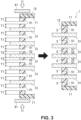
- the laminated material 11 is provided to cover the electric power generating element 2. As illustrated in the left view of Fig. 3 , an edge of the laminated material 11 may be located at a position that corresponds to the resins 51, 52 aligned in the stacking direction, and may be located on an outer side of the outermost current collector 31 in the stacking direction. In other words, in the left view of Fig. 3 , the edges of the laminated material 11 may be respectively located above the uppermost current collector 31 and below the lowermost current collector 31 in a vertical direction.
- the resin 51 is also welded to the edge of the laminated material 11.
- the resin 51 may not be provided to the edge of the laminated material 11.
- the laminated material 11 is welded to the current collector 31 by a resin material that is contained in the laminated material 11.
- the resins 51, 52 that are aligned in the stacking direction are welded to each other.
- the resins 51, 52 may be heat-plate welded. More specifically, as indicated by blank arrows in the left view of Fig. 3 , two heat plates 61, 61, each of which is located on the outer side of the respective laminated material 11, pressurize and heat the resins 51, 52, which are aligned in the stacking direction, from the outer side to the center in the stacking direction (that is, a second step).
- Thermal energy from the two heat plates 61, 61 is transferred from the outer side toward the center in the stacking direction through the laminated material 11, the resins 51, 52, and the current collectors 31, and the resins 51, 52 that are adjacent to each other in the stacking direction receive the thermal energy and are welded together.
- the opening (the first opening 12 herein) of the pouch 10 between the laminated material 11 and the current collector 31 and the opening thereof between the current collectors 31 are sealed by the welded resin 5 (that is, a third step).
- the battery cell 1 may have large numbers of the first electrode sheets 3 and the second electrode sheets 4.
- the resin 52 that is located at the center in the stacking direction may be away from the heat plates 61, 61.
- the thermal energy that is supplied to the resin 52 located at the center in the stacking direction may attenuate during the transfer through the large number of the current collectors 31 and the large number of the resins 51, and thus may be lower than the thermal energy that is supplied to the resin 51 located on the outer side in the stacking direction. A reduction in the supply energy possibly results in insufficient welding of the resin 52.
- not all of the resins 51, 52 of the first electrode sheet(s) 3 and the resin of the second electrode sheet(s) 4 have the same thickness in the stacking direction.
- the thickness of the resin located at the center in the stacking direction that is, a thickness T2 of the second resin 52 is less than the thickness of the resin located on the outer side in the stacking direction, that is, a thickness T1 of the first resin 51.
- a volume of the second resin 52 is relatively small.
- the second resins 52 are welded to the upper surface and the lower surface of the current collector 31 that is located at the center in the stacking direction.
- the number of the current collectors 31, to which the second resins 52 are welded is not limited to one.
- the second resins 52 may be welded to the plural current collectors 31 that are located at the center in the stacking direction. In addition, welding of the second resins 52 is not limited to that to both of the upper surface and the lower surface of the current collector 31.
- the second resin 52 may be welded to one of the upper surface and the lower surface of each current collector 31, and the first resin 51 may be welded to the other of the upper surface and the lower surface of each current collector 31.
- the supply energy per unit volume to the second resin 52 may be equivalent to the supply energy per unit volume to the first resin 51. Even when the supply energy to the second resin 52 is relatively low, the second resin 52 ensures sufficient welding together with another resin. On the contrary, even when the supply energy to the first resin 51 is relatively high, the first resin 51 ensures stable welding with another resin without excessive melting. In this way, it is possible to suppress insufficient welding of the resins 51, 52 during manufacturing of the battery cell 1.
- the manufactured battery cell 1 has a characteristic that a thickness (T1 + T2) in the stacking direction of the resin 5 located at the center in the stacking direction is less than a thickness (T1 + T1) in the stacking direction of the resin 5 located on the outer side in the stacking direction.
- the battery cell 1 that has this structural characteristic suppresses insufficient welding of the resins 51, 52 during manufacturing, and thus can stabilize quality.
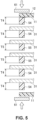
- Fig. 4 illustrates a modified example related to the thickness of the resin.
- the thickness T2 of the second resin 52 which is located at the center in the stacking direction, is less than the thickness T1 of the first resin 51, which is located on the outer side in the stacking direction.
- a thickness T3 of a third resin 53 that is located between the first resin 51 and the second resin 52 is less than the thickness T1 and greater than the thickness T2. That is, the thicknesses of the resins 51, 52, 53 are reduced particularly in a stepwise manner from the outer side to the center in the stacking direction.
- the thermal energy for welding is transferred in an order of the first resin 51, the third resin 53, and the second resin 52.
- the supply energy per unit volume to the third resin 53 may be equivalent to the supply energy per unit volume to the second resin 52 or the supply energy per unit volume to the first resin 51.
- the first resin 51, the second resin 52, and the third resin 53 are each supplied with the energy commensurate with the volume thereof.
- Each of the first resin 51, the second resin 52, and the third resin 53 can be welded sufficiently with another resin.
- the number of the current collectors 31, to which the third resin 53 is welded, is appropriately set.
- welding of the third resin 53 is not limited to that to both of the upper surface and the lower surface of the current collector(s) 31.
- the third resin 53 may be welded to one of the upper surface and the lower surface of the current collector 31, and the first resin 51 or the second resin 52 may be welded to the other of the upper surface and the lower surface of the current collector 31.
- Fig. 5 illustrates a modified example related to the form of the resin that is welded to the current collector.
- each of the resins 51, 52 is welded to both of the surfaces of the current collector 31 (or the current collector 41) in advance.
- each of a first resin 54 and a second resin 55 is welded to only one of the surfaces of the current collector 31 (or the current collector 41) in advance.
- the first resin 54 is welded to one of the two edges of the laminated materials 11 in advance.
- a thickness T5 of the second resin 55, which is located at the center in the stacking direction, is less than a thickness T4 of the first resin 54, which is located on the outer side in the stacking direction.
- the resins 54, 55 are welded to the current collector(s) 31 or the laminated material 11 instead of another resin.
- the supply energy per unit volume to the second resin 55 may be equivalent to the supply energy per unit volume to the first resin 54.
- the second resin 55 can sufficiently be welded to the current collector 31.
- the first resin 54 can also sufficiently be welded to the current collector 31 or the laminated material 11. In this way, it is possible to suppress insufficient welding of the resins 54, 55 during manufacturing of the battery cell 1.
- Fig. 6 illustrates a modified example related to a melting point of the resin.
- the resins 51 to 55 in the battery cells 1 illustrated in Figs. 3 to 5 vary in thickness.
- the resins 51 to 55 may be the same type of the resin, and the resins 51 to 55 may have the same melting point.
- resins 56, 57 have different melting points. More specifically, the melting point of the second resin 57, which is located at the center in the stacking direction, is lower than the melting point of the first resin 56, which is located on the outer side in the stacking direction.
- the first resin 56 with the relatively high melting point can be selected from biaxially oriented polypropylene (OPP), polyethylene terephthalate (PET), and biaxially oriented nylon (ONY), for example.
- the melting point of the first resin 56 may be in a range of 165 to 264°C, for example.
- the second resin 57 with the relatively low melting point can be selected from cast polypropylene (CPP), low-density polyethylene (LDPE), linear low-density polyethylene (LLDPE), and high-density polyethylene (HDPE), for example.
- the melting point of the second resin 57 may be in a range 105 to 165°C or 105 to 164°C.
- An additive may be added to the second resin 57 to lower the melting point.
- any of phthalate-based additive, phosphate-based additive, fatty acid ester-based additive, polyester-based additive, epoxy-based additive, and sulfonamide-based additive may be used.
- the second resin 57 with the low melting point can sufficiently be welded even with the low supplied thermal energy. Meanwhile, since the high thermal energy is supplied to the first resin 56 with the high melting point, the first resin 56 can sufficiently be welded. In this way, it is possible to suppress insufficient welding of the resins 56, 57 during manufacturing of the battery cell 1.
- the manufactured battery cell 1 has a characteristic that the melting point of the resin 5 located at the center in the stacking direction is lower than the melting point of the resin 5 located on the outer side in the stacking direction. That is, of the resins 5 that are welded to the current collectors 31 at the positions between the current collectors 31, the resin 5 located at the center in the stacking direction contains the resin 57 with the low melting point.
- the battery cell 1 that has this structural characteristic suppresses insufficient welding of the resins 56, 57 during manufacturing, and thus can stabilize the quality.
- the thickness T1 of the second resin 57 in the stacking direction may be the same as the thickness T1 of the first resin 56. However, the thickness of the second resin 57 in the stacking direction may be less than the thickness T1 of the first resin 56.
- the number of the current collectors 31, to which the second resin(s) 57 is(are) welded, is appropriately set.
- welding of the second resin 57 is not limited to that to both of the upper surface and the lower surface of the current collector 31.
- the second resin 57 may be welded to one of the upper surface and the lower surface of the current collector 31, and the first resin 56 may be welded to the other of the upper surface and the lower surface of the current collector 31.
- the second resins 52, 55 are thin in order to increase the supply energy per unit voltage to the second resins 52, 55, each of which is located at the center in the stacking direction.
- the second resin 57 which is located at the center in the stacking direction, has the low melting point such that the second resin 57 is welded even when the energy received by the second resin 57 is low.
- the battery cell 1 in Fig. 7 promotes energy transfer to increase an amount of the energy supplied to the second resin 52, which is located at the center in the stacking direction. More specifically, the battery cell 1 in Fig. 7 uses a fact that the current collector 31 made of the metal has higher energy transfer efficiency than the resins 51, 52.
- thicknesses T6, T7 of portions, to each of which respective one of the resins 51, 52 is welded are greater than a thickness T8 of the other portions. It can be rephrased that the current collector 31 has one or two projections 34 in the portion, to which one of the resins 51, 52 is welded. The thicknesses of the resins 51, 52 may be reduced due to the thicknesses T6, T7 of the current collectors 31.
- the thickness T2 of the second resin 52 which is located at the center in the stacking direction, is less than the thickness T1 of the first resin 51, which is located on the outer side in the stacking direction.
- the thickness of the second resin 52 may be the same as the thickness T1 of the first resin 51.
- the thermal energy from the heat plates 61, 61 is transferred to the second resin 52 through the first resin 51 and the current collector 31.
- the thickness of the first resin 51 is reduced due to the large thickness of the current collector 31. Since the current collector 31, which is made of the metal, has relatively low specific heat, attenuation of the thermal energy up to reaching to the second resin 52 is suppressed.
- the second resin 52 can receive the sufficient thermal energy for welding. In this way, it is possible to suppress insufficient welding of the resins 51, 52 during manufacturing of the battery cell 1.
- All of the current collectors 31 may have the single projection 34, or all of the current collectors 31 may have the two projections 34.
- the second resin 52 may be the resin with the lower melting point than the first resin 51.
- Fig. 8 illustrates a modified example of the method of manufacturing the battery cell 1. More specifically, in this manufacturing method, not only the heat plates 61, 61, each of which is located on the outer side in the stacking direction, (that is, first heat sources 61, 61) but also second heat sources 62, 62 are used during welding of the resins 56, 57.
- the second heat sources 62, 62 may be connected to the current collector 31 that is in contact with the second resins 57 located at the center in the stacking direction. A projection length of this current collector 31 may be longer than those of the other current collectors 31. This current collector 31 may have a connection allowance for the second heat sources 62, 62.
- the number of the current collectors 31, to which the second heat sources 62, 62 are connected, is not limited to one but may be plural.
- the first heat sources 61, 61 pressurize and heat the resins 56, 57 in the stacking direction.
- the second heat sources 62, 62 supply the thermal energy to the resins 57 through the current collector 31.
- the second resin 57 receives the thermal energy from the first heat sources 61, 61 and the second heat sources 62, 62. In this way, the second resin 57 can sufficiently be welded.
- the first resin 56 can also sufficiently be welded.
- the second resin 57 may be a different type of the resin from the first resin 56, and the melting point thereof may be relatively low, for example.
- the second resin 57 may be of the same type as the first resin 56.
- the thickness of the second resin 57 may be less than or the same as the thickness of the first resin 56.
- Heat-plate welding is performed in the above description.
- the resins may be welded by vibration welding, ultrasonic welding, or high-frequency welding, for example.
- all of the above-described configurations ensure sufficient welding of the resin, which is located at the center in the stacking direction, even with the attenuation of the energy for welding.
Landscapes
- Chemical & Material Sciences (AREA)
- Chemical Kinetics & Catalysis (AREA)
- Electrochemistry (AREA)
- General Chemical & Material Sciences (AREA)
- Engineering & Computer Science (AREA)
- Manufacturing & Machinery (AREA)
- Materials Engineering (AREA)
- Sealing Battery Cases Or Jackets (AREA)
- Secondary Cells (AREA)
- Connection Of Batteries Or Terminals (AREA)
Abstract
Description
- The present invention relates to a battery cell and a method of manufacturing a battery cell.
- A conventional laminated battery is disclosed in Patent Literature 1. The conventional laminated battery is a battery in which an electrode body is accommodated in an exterior member. The conventional laminated battery includes plural current-collecting terminals that are drawn from the electrode body to the outside of the exterior member. The plural current-collecting terminals are superimposed on each other with a thermoplastic resin being interposed between two each of the plural current-collecting terminals. A peripheral edge portion of the exterior member is closed by welding the thermoplastic resin to the peripheral edge portion of the exterior member. In this conventional laminated battery, each of the plural current-collecting terminals is drawn to the outside of the exterior member, and the plural current-collecting terminals are not connected to each other in the exterior member. In this conventional laminated battery, a space inside the exterior member can be used to enlarge the electrode body, which is advantageous for improving energy density of the battery.
- [Patent Literature 1]
JP2009-272161A - The conventional laminated battery is manufactured by a heat-sealing process. In the heat-sealing process, the thermoplastic resins superimposed on each other in the peripheral edge portion of the exterior member are welded to each other by pressing a heat plate as an energy supply source against the thermoplastic resins in a superimposed direction.
- Here, when the number of current collectors is increased in a battery cell that has the same structure as the conventional laminated battery, a large number of stacked resins have to be welded together during manufacturing of the battery cell. When the large number of the resins are stacked on each other, the resin at a center in a stacking direction is located far away from the energy supply source. As a result, there is a possibility that sufficient energy is not supplied to the resin located at the center, which results in insufficient welding of the resin located at the center.
- The object of the present invention is to suppress insufficient welding of a resin during manufacturing of a battery cell.
- The above object is achieved by the present invention as defined in independent claims. Particularly, a battery cell includes:
- a pouch that accommodates electrodes;
- plural current collectors, each of which is connected to a corresponding one of the electrodes in the pouch, the plural current collectors being stacked in a stacking direction, the plural current collectors projecting to the outside of the pouch through an opening of the pouch;
- a first resin that seals the opening of the pouch, the first resin being welded to the current collector at a position between the stacked current collectors; and
- a second resin that seals the opening of the pouch, the second resin being welded to the current collector at a position between the stacked current collectors, being located closer to a center in the stacking direction than the first resin is to the center, and being thinner than the first resin in the stacking direction.
- In the battery cell, each of the plural stacked current collectors projects to the outside of the pouch through the opening of the pouch. The plural current collectors are connected to the electrodes with the same polarity, for example. In the pouch, the plural current collectors are not mutually connected. Thus, a space for connecting the current collectors in the pouch can be eliminated. As a result, the electrodes of the battery cell can be enlarged by using the space in the pouch. In this way, energy density of the battery cell can be increased.
- The opening of the pouch is sealed by the first resin and the second resin. The first resin and the second resin are supplied with energy for welding during manufacturing of the battery cell. Each of the first resin and the second resin is a thermoplastic resin, for example. The energy supplied to the first resin and the second resin is thermal energy, for example. However, the energy for welding is not limited to the thermal energy. The energy may be vibration energy, for example. An interface between the first resin and the second resin, each of which is supplied with the vibration energy, is welded by frictional heat.
- The current collectors, the first resin, and the second resin are stacked in the stacking direction. An energy supply source, such as a heat plate, is located on the outer side in the stacking direction and supplies the energy from the outer side toward the center. The energy is transferred to the second resin through the current collectors and the first resin. Due to attenuation of the energy, the energy supplied to the second resin, which is located at the center in the stacking direction, is lower than the energy supplied to the first resin, which is located on the outer side in the stacking direction.
- Here, the second resin is thinner than the first resin in the stacking direction. Although the energy supplied to the second resin is low, the supply energy per unit volume to the second resin is equivalent to the supply energy per unit volume to the first resin. Since the energy commensurate with the volume is supplied to the second resin, the second resin can sufficiently be welded to the current collector or another resin. Since the energy commensurate with the volume is also supplied to the first resin, the first resin can also sufficiently be welded to the current collector or another resin. In this way, it is possible to suppress insufficient welding of the resin during manufacturing of the battery cell.
- The battery cell may further include a third resin that seals the opening of the pouch, the third resin being welded to the current collector at a position between the stacked current collectors, being located between the first resin and the second resin in the stacking direction, being thinner than the first resin in the stacking direction, and being thicker than the second resin in the stacking direction.
- The third resin is located between the first resin and the second resin in the stacking direction. The energy for welding is transferred in an order of the first resin, the third resin, and the second resin.
- The thickness of the third resin in the stacking direction is less than the thickness of the first resin and greater than the thickness of the second resin. The supply energy per unit volume to the third resin is equivalent to the supply energy per unit volume to the second resin or the supply energy per unit volume to the first resin. Since the energy commensurate with the volume is supplied to the first resin, the second resin, and the third resin, each of the first resin, the second resin, and the third resin can stably and sufficiently be welded to the current collector or another resin.
- Portions of the current collectors, to which the first resin and the second resin are welded, may be thicker than the other portions thereof in the stacking direction.
- For example, the current collector that is made of metal has higher energy transfer efficiency for welding than the resin, and examples of the energy are thermal energy and vibration energy. The metallic current collector has lower specific heat than the resin. The metallic current collector has higher Young's modulus than the resin. The current collector transfers the energy for welding relatively easily. In the case where the portion of the current collector, to which the resin is welded, is thick, the thickness of the resin is reduced. As a result, attenuation of the energy is suppressed during the energy transfer for welding in the stacking direction. The suppression of the energy attenuation is advantageous for the energy supply to the second resin at the center.
- The second resin may have a lower melting point than the first resin.
- In the case where the second resin has the low melting point, the second resin can be welded to the current collector or another resin even with the low supply energy to the second resin. The second resin with the low melting point can suppress insufficient welding of the resin.
- Further particularly, a battery cell includes:
- a pouch that accommodates electrodes;
- plural current collectors, each of which is connected to a corresponding one of the electrodes in the pouch, the plural current collectors being stacked in a stacking direction, the plural current collectors projecting to the outside of the pouch through an opening of the pouch;
- a first resin that seals the opening of the pouch, the first resin being welded to the current collector at a position between the stacked current collectors; and
- a second resin that seals the opening of the pouch, the second resin being welded to the current collector at a position between the stacked current collectors, being located closer to a center in the stacking direction than the first resin is to the center, and having a lower melting point than the first resin.
- As described above, in the case where the second resin has the low melting point, the second resin can be welded even with the low supply energy to the second resin. Therefore, it is possible to suppress insufficient welding of the resin.
- An additive may be added to the second resin. The additive may be configured to lower the melting point.
- Use of the additive is effective in lowering the melting point of the resin.
- Further particularly, a method of manufacturing a battery cell includes:
- stacking electrode sheets in a stacking direction, each of the electrode sheets having: an electrode located in a pouch; and a current collector connected to the electrode in the pouch and projecting to the outside from an opening of the pouch;
- pressurizing and heating a first resin and a second resin from an outer side toward a center in the stacking direction, the first resin being located between the stacked current collectors, the second resin being located between the current collectors and closer to the center in the stacking direction than the first resin is to the center, and being thinner than the first resin in the stacking direction; and
- at positions between the current collectors, welding the first resin and welding the second resin to seal the opening of the pouch.
- When the electrode sheets are stacked during manufacturing of the battery cell, the plural current collectors, the first resin, and the second resin are stacked in the stacking direction, and the first resins and the second resins are located between the current collectors. The current collectors, the first resin, and the second resin are pressurized and heated from the outer side toward the center in the stacking direction. The thermal energy is transferred to the second resin through the current collector and the first resin.
- The second resin is thinner than the first resin in the stacking direction. The thermal energy per unit volume supplied to the second resin is equivalent to the thermal energy per unit volume supplied to the first resin. The second resin can sufficiently be welded by the supplied thermal energy. The first resin can also be welded stably and sufficiently. In this way, it is possible to suppress insufficient welding of the resin during manufacturing of the battery cell.
- Further particularly, a method of manufacturing the battery cell includes:
- stacking electrode sheets in a stacking direction, each of the electrode sheets having: an electrode located in a pouch; and a current collector connected to the electrode in the pouch and projecting to the outside from an opening of the pouch;
- pressurizing and heating a first resin and a second resin from an outer side toward a center in the stacking direction, the first resin being located between the stacked current collectors, the second resin being located between the current collectors and closer to the center in the stacking direction than the first resin is to the center, and having a lower melting point than the first resin; and
- at positions between the current collectors, welding the first resin and welding the second resin to seal the opening of the pouch.
- The second resin has the lower melting point than the first resin. Even when the thermal energy supplied to the second resin is low, the second resin can sufficiently be welded by the supplied thermal energy. Meanwhile, since the high thermal energy is supplied to the first resin with the high melting point, the first resin can sufficiently be welded. In this way, it is possible to suppress insufficient welding of the resin during manufacturing of the battery cell.
- The manufacturing method may further include: heating the second resin through the current collector that is in contact with the second resin during pressurizing and heating of the first resin and the second resin.
- To the second resin at the center in the stacking direction, the thermal energy is supplied not only in the stacking direction, the thermal energy is supplied but also through the current collector. Therefore, the second resin at the center in the stacking direction can be welded stably and sufficiently.
- According to the battery cell and the method of manufacturing the battery cell, it is possible to suppress insufficient welding of the resin during manufacturing of the battery cell.
-
- [
Fig. 1] Fig. 1 is a cross-sectional view of a battery cell. - [
Fig. 2] Fig. 2 is a perspective view of an electric power generating element that is accommodated in a pouch. - [
Fig. 3] Fig. 3 includes views in which a left view illustrates a state before welding of a resin for sealing an opening of the pouch, and a right view illustrates a state after welding of the resin. - [
Fig. 4] Fig. 4 illustrates a structure of a battery cell according to a modified example. - [
Fig. 5] Fig. 5 illustrates a structure of a battery cell according to another modified example. - [
Fig. 6] Fig. 6 includes views in which a left view illustrates a state before welding of a resin in the battery cell according to the modified example, and a right view illustrates a state after welding of the resin. - [
Fig. 7] Fig. 7 illustrates a structure of a battery cell according to further another modified example. - [
Fig. 8] Fig. 8 illustrates a method of manufacturing the battery cell according to the modified example. - A description will hereinafter be made on embodiments of a battery cell and a method of manufacturing a battery cell with reference to the drawings. The battery cell and the method of manufacturing a battery cell described herein are merely illustrative.
-
Fig. 1 schematically illustrates an overall structure of a battery cell 1.Fig. 2 illustrates an electricpower generating element 2 that is accommodated in a pouch (or a container, or a package) 10 of the battery cell 1. The battery cell 1 may be a secondary battery. The battery cell 1 may be a lithium-ion battery, for example. - The
pouch 10 of the battery cell 1 may be formed by folding alaminated material 11 or superimposing twolaminated materials 11 in a bag shape. Thelaminated material 11 may have a multi-layer structure, particularly a three-layer structure in which a metal layer is sandwiched between two resin layers on both sides, for example. The metal layer may be made of aluminum or stainless steel, for example. The resin layer may be made of polypropylene (PP) or polyethylene (PE), for example. - The
pouch 10 is sealed in a state of containing the electricpower generating element 2 and an electrolyte. The battery cell 1 is a so-called pouch-type battery. - The electric
power generating element 2 has one or morefirst electrode sheets 3 and one or moresecond electrode sheets 4. Thefirst electrode sheet 3 may be an anode sheet, for example. Thesecond electrode sheet 4 may be a cathode sheet, for example. However, thefirst electrode sheet 3 may be the cathode sheet, and thesecond electrode sheet 4 may be the anode sheet. Thefirst electrode sheets 3 and thesecond electrode sheets 4 are alternately superimposed on each other. Appropriate numbers of thefirst electrode sheets 3 and thesecond electrode sheets 4 can be used in the electricpower generating element 2. The electricpower generating element 2 is an electrode stack. Hereinafter, a direction in which thefirst electrode sheets 3 and thesecond electrode sheets 4 are stacked may be referred to as a stacking direction. - The
first electrode sheet 3 has a current collector 31 (i.e., thefirst electrode sheets 3 have current collectors 31). Thecurrent collector 31 is a thin plate material that extends in a direction orthogonal to the stacking direction. A first end portion of thecurrent collector 31, that is, a left end portion thereof inFig. 1 , projects from afirst opening 12 of thepouch 10 to the outside of thepouch 10. - Portions of upper and lower surfaces of the
current collector 31, which are located inside thepouch 10, may be each coated with an active material. The active material may form afirst electrode 32. Thecurrent collector 31 is connected to thefirst electrode 32. - The
first electrode sheet 3 has a separator 33 (i.e., thefirst electrode sheets 3 have separators 33). Theseparator 33 separates thefirst electrode 32 of thefirst electrode sheet 3 from asecond electrode 42 of thesecond electrode sheet 4. Thesecond electrode 42 will be described below. - The
separator 33 may be a porous material through which an ionic material can permeate, for example. The separator(s) 33 covers a surface of each of the twofirst electrodes 32 in thefirst electrode sheet 3. An area of theseparator 33 may be larger than an area of thefirst electrode sheet 3. - The
second electrode sheet 4 has a current collector 41 (i.e., thesecond electrode sheets 4 have current collectors 41). Thecurrent collector 41 is a thin plate material that extends in the direction orthogonal to the stacking direction. A second end portion of thecurrent collector 41, that is, a right end portion thereof inFig. 1 , projects from asecond opening 13 of thepouch 10 to the outside of thepouch 10. - The
second opening 13 may be an opposite opening from thefirst opening 12 in the direction orthogonal to the stacking direction. A projecting direction of thecurrent collector 41 is not limited to an opposite direction from a projecting direction of thecurrent collector 31. - Portions of upper and lower surfaces of the
current collector 41, which are located inside thepouch 10, may be each coated with the active material. The active material may form thesecond electrode 42. Thecurrent collector 41 is connected to thesecond electrode 42. - As described above, the
first electrode sheets 3 and thesecond electrode sheets 4 are alternately stacked on each other. In thepouch 10, thefirst electrode sheets 32 and thesecond electrode sheets 42 are stacked in the stacking direction via theseparators 33. - The
first opening 12 of thepouch 10 is sealed by aresin 5. Theresin 5 is located between thelaminated material 11 and thecurrent collector 31 and between thecurrent collectors 31. - Similarly, the
second opening 13 is sealed by theresin 5. Theresin 5 is located between thelaminated material 11 and thecurrent collector 41 and between thecurrent collectors 41. - The plural
current collectors 31 separately project to the outside of thepouch 10 without being connected to each other in thepouch 10. Similarly, the pluralcurrent collectors 41 separately project to the outside of thepouch 10 without being connected to each other in thepouch 10. - Since a space for connecting the
current collectors 31 and a space for connecting thecurrent collectors 41 can be eliminated in thepouch 10, areas for thefirst electrodes 32 and thesecond electrodes 42 can be increased by an area of elimination. As a result, energy density of the battery cell 1 can be increased. - Next, a description will be made on a method of manufacturing the battery cell 1 with reference to
Fig. 2 andFig. 3 . A description will herein be made on the method of manufacturing the battery cell 1 by using welding of the resin in thefirst opening 12 as an example. The same also applied to welding of the resin in thesecond opening 13. - First, the
first electrode sheets 3 and thesecond electrode sheets 4 are prepared. As described above, the first electrode sheet(s) 3 has the current collector(s) 31, the first electrode(s) 32, and the separator(s) 33. The second electrode sheet(s) 4 has the current collector(s) 41 and the second electrode(s) 42. - The
first electrode sheets 3 and thesecond electrode sheets 4 are alternately stacked on each other. Thefirst electrode 32 and thesecond electrode 42 are superimposed on each other via theseparator 33. As illustrated inFig. 2 , the electricpower generating element 2 is formed which has the pluralfirst electrode sheets 3 and the plural second electrode sheets 4 (that is, a first step). - Here, as illustrated in
Fig. 2 and the left view ofFig. 3 , in or on the current collector(s) 31 of thefirst electrode sheet 3, resins 51, 52 are welded to a portion (or portions) between the first end portion(s) and the first electrode(s) 32 in advance. Theresins current collector 31. - Each of the
resins current collector 31 in the direction orthogonal to the stacking direction. Theresins resin 5 that seals thefirst opening 12 of thepouch 10. In the electricpower generating element 2, theresins second electrode 42. - Each of the
resins resins - After the electric
power generating element 2 is formed, thelaminated material 11 is provided to cover the electricpower generating element 2. As illustrated in the left view ofFig. 3 , an edge of thelaminated material 11 may be located at a position that corresponds to theresins current collector 31 in the stacking direction. In other words, in the left view ofFig. 3 , the edges of thelaminated material 11 may be respectively located above the uppermostcurrent collector 31 and below the lowermostcurrent collector 31 in a vertical direction. - The
resin 51 is also welded to the edge of thelaminated material 11. However, for example, theresin 51 may not be provided to the edge of thelaminated material 11. In this case, thelaminated material 11 is welded to thecurrent collector 31 by a resin material that is contained in thelaminated material 11. - Next, the
resins resins Fig. 3 , twoheat plates laminated material 11, pressurize and heat theresins - Thermal energy from the two
heat plates laminated material 11, theresins current collectors 31, and theresins Fig. 3 , the opening (thefirst opening 12 herein) of thepouch 10 between thelaminated material 11 and thecurrent collector 31 and the opening thereof between thecurrent collectors 31 are sealed by the welded resin 5 (that is, a third step). - Here, the battery cell 1 may have large numbers of the
first electrode sheets 3 and thesecond electrode sheets 4. During welding of theresins resin 52 that is located at the center in the stacking direction may be away from theheat plates resin 52 located at the center in the stacking direction may attenuate during the transfer through the large number of thecurrent collectors 31 and the large number of theresins 51, and thus may be lower than the thermal energy that is supplied to theresin 51 located on the outer side in the stacking direction. A reduction in the supply energy possibly results in insufficient welding of theresin 52. - In this respect, particularly, not all of the
resins second resin 52 is less than the thickness of the resin located on the outer side in the stacking direction, that is, a thickness T1 of thefirst resin 51. A volume of thesecond resin 52 is relatively small. The second resins 52 are welded to the upper surface and the lower surface of thecurrent collector 31 that is located at the center in the stacking direction. Here, the number of thecurrent collectors 31, to which thesecond resins 52 are welded, is not limited to one. The second resins 52 may be welded to the pluralcurrent collectors 31 that are located at the center in the stacking direction. In addition, welding of thesecond resins 52 is not limited to that to both of the upper surface and the lower surface of thecurrent collector 31. Thesecond resin 52 may be welded to one of the upper surface and the lower surface of eachcurrent collector 31, and thefirst resin 51 may be welded to the other of the upper surface and the lower surface of eachcurrent collector 31. - The supply energy per unit volume to the
second resin 52 may be equivalent to the supply energy per unit volume to thefirst resin 51. Even when the supply energy to thesecond resin 52 is relatively low, thesecond resin 52 ensures sufficient welding together with another resin. On the contrary, even when the supply energy to thefirst resin 51 is relatively high, thefirst resin 51 ensures stable welding with another resin without excessive melting. In this way, it is possible to suppress insufficient welding of theresins - As illustrated in the right view of
Fig. 3 , in regard to theresins 5 for sealing thefirst opening 12 and/or thesecond opening 13 of thepouch 10, the manufactured battery cell 1 has a characteristic that a thickness (T1 + T2) in the stacking direction of theresin 5 located at the center in the stacking direction is less than a thickness (T1 + T1) in the stacking direction of theresin 5 located on the outer side in the stacking direction. The battery cell 1 that has this structural characteristic suppresses insufficient welding of theresins -
Fig. 4 illustrates a modified example related to the thickness of the resin. In or on thefirst electrode sheet 3 ofFig. 4 , the thickness T2 of thesecond resin 52, which is located at the center in the stacking direction, is less than the thickness T1 of thefirst resin 51, which is located on the outer side in the stacking direction. In addition, a thickness T3 of athird resin 53 that is located between thefirst resin 51 and thesecond resin 52 is less than the thickness T1 and greater than the thickness T2. That is, the thicknesses of theresins - The thermal energy for welding is transferred in an order of the
first resin 51, thethird resin 53, and thesecond resin 52. The supply energy per unit volume to thethird resin 53 may be equivalent to the supply energy per unit volume to thesecond resin 52 or the supply energy per unit volume to thefirst resin 51. Thefirst resin 51, thesecond resin 52, and thethird resin 53 are each supplied with the energy commensurate with the volume thereof. Each of thefirst resin 51, thesecond resin 52, and thethird resin 53 can be welded sufficiently with another resin. - The number of the
current collectors 31, to which thethird resin 53 is welded, is appropriately set. In addition, welding of thethird resin 53 is not limited to that to both of the upper surface and the lower surface of the current collector(s) 31. Thethird resin 53 may be welded to one of the upper surface and the lower surface of thecurrent collector 31, and thefirst resin 51 or thesecond resin 52 may be welded to the other of the upper surface and the lower surface of thecurrent collector 31. -
Fig. 5 illustrates a modified example related to the form of the resin that is welded to the current collector. In or on the first electrode sheet 3 (and the second electrode sheet 4) illustrated inFig. 3 orFig. 4 , each of theresins Fig. 5 , each of afirst resin 54 and asecond resin 55 is welded to only one of the surfaces of the current collector 31 (or the current collector 41) in advance. In addition, thefirst resin 54 is welded to one of the two edges of thelaminated materials 11 in advance. - A thickness T5 of the
second resin 55, which is located at the center in the stacking direction, is less than a thickness T4 of thefirst resin 54, which is located on the outer side in the stacking direction. - The
resins laminated material 11 instead of another resin. During welding of theresins second resin 55 may be equivalent to the supply energy per unit volume to thefirst resin 54. Thesecond resin 55 can sufficiently be welded to thecurrent collector 31. Thefirst resin 54 can also sufficiently be welded to thecurrent collector 31 or thelaminated material 11. In this way, it is possible to suppress insufficient welding of theresins -
Fig. 6 illustrates a modified example related to a melting point of the resin. Theresins 51 to 55 in the battery cells 1 illustrated inFigs. 3 to 5 vary in thickness. Theresins 51 to 55 may be the same type of the resin, and theresins 51 to 55 may have the same melting point. - In the battery cell 1 of
Fig. 6 , resins 56, 57 have different melting points. More specifically, the melting point of thesecond resin 57, which is located at the center in the stacking direction, is lower than the melting point of thefirst resin 56, which is located on the outer side in the stacking direction. - Here, the
first resin 56 with the relatively high melting point can be selected from biaxially oriented polypropylene (OPP), polyethylene terephthalate (PET), and biaxially oriented nylon (ONY), for example. The melting point of thefirst resin 56 may be in a range of 165 to 264°C, for example. - The
second resin 57 with the relatively low melting point can be selected from cast polypropylene (CPP), low-density polyethylene (LDPE), linear low-density polyethylene (LLDPE), and high-density polyethylene (HDPE), for example. The melting point of thesecond resin 57 may be in a range 105 to 165°C or 105 to 164°C. - An additive may be added to the
second resin 57 to lower the melting point. For example, any of phthalate-based additive, phosphate-based additive, fatty acid ester-based additive, polyester-based additive, epoxy-based additive, and sulfonamide-based additive may be used. - During welding of the
resins Fig. 6 , thesecond resin 57 with the low melting point can sufficiently be welded even with the low supplied thermal energy. Meanwhile, since the high thermal energy is supplied to thefirst resin 56 with the high melting point, thefirst resin 56 can sufficiently be welded. In this way, it is possible to suppress insufficient welding of theresins - As illustrated in a right view of
Fig. 6 , in regard to theresins 5 for sealing thefirst opening 12 and/or thesecond opening 13 of thepouch 10, the manufactured battery cell 1 has a characteristic that the melting point of theresin 5 located at the center in the stacking direction is lower than the melting point of theresin 5 located on the outer side in the stacking direction. That is, of theresins 5 that are welded to thecurrent collectors 31 at the positions between thecurrent collectors 31, theresin 5 located at the center in the stacking direction contains theresin 57 with the low melting point. The battery cell 1 that has this structural characteristic suppresses insufficient welding of theresins - In
Fig. 6 , the thickness T1 of thesecond resin 57 in the stacking direction may be the same as the thickness T1 of thefirst resin 56. However, the thickness of thesecond resin 57 in the stacking direction may be less than the thickness T1 of thefirst resin 56. - The number of the
current collectors 31, to which the second resin(s) 57 is(are) welded, is appropriately set. In addition, welding of thesecond resin 57 is not limited to that to both of the upper surface and the lower surface of thecurrent collector 31. Thesecond resin 57 may be welded to one of the upper surface and the lower surface of thecurrent collector 31, and thefirst resin 56 may be welded to the other of the upper surface and the lower surface of thecurrent collector 31. -
Fig. 7 illustrates a modified example related to a shape of the current collector. The battery cells 1 inFigs. 3 to 6 are structured such that thesecond resins second resins - In detail, in the battery cells 1 illustrated in
Figs. 3 to 5 , thesecond resins second resins Fig. 6 , thesecond resin 57, which is located at the center in the stacking direction, has the low melting point such that thesecond resin 57 is welded even when the energy received by thesecond resin 57 is low. - The battery cell 1 in
Fig. 7 promotes energy transfer to increase an amount of the energy supplied to thesecond resin 52, which is located at the center in the stacking direction. More specifically, the battery cell 1 inFig. 7 uses a fact that thecurrent collector 31 made of the metal has higher energy transfer efficiency than theresins - In the
current collector 31, thicknesses T6, T7 of portions, to each of which respective one of theresins current collector 31 has one or twoprojections 34 in the portion, to which one of theresins resins current collectors 31. - In the battery cell 1 of
Fig. 7 , the thickness T2 of thesecond resin 52, which is located at the center in the stacking direction, is less than the thickness T1 of thefirst resin 51, which is located on the outer side in the stacking direction. In contrast, the thickness of thesecond resin 52 may be the same as the thickness T1 of thefirst resin 51. - During welding of the
resins heat plates second resin 52 through thefirst resin 51 and thecurrent collector 31. The thickness of thefirst resin 51 is reduced due to the large thickness of thecurrent collector 31. Since thecurrent collector 31, which is made of the metal, has relatively low specific heat, attenuation of the thermal energy up to reaching to thesecond resin 52 is suppressed. Thesecond resin 52 can receive the sufficient thermal energy for welding. In this way, it is possible to suppress insufficient welding of theresins - All of the
current collectors 31 may have thesingle projection 34, or all of thecurrent collectors 31 may have the twoprojections 34. In addition, thesecond resin 52 may be the resin with the lower melting point than thefirst resin 51. -
Fig. 8 illustrates a modified example of the method of manufacturing the battery cell 1. More specifically, in this manufacturing method, not only theheat plates first heat sources 61, 61) but alsosecond heat sources resins - The
second heat sources current collector 31 that is in contact with thesecond resins 57 located at the center in the stacking direction. A projection length of thiscurrent collector 31 may be longer than those of the othercurrent collectors 31. Thiscurrent collector 31 may have a connection allowance for thesecond heat sources current collectors 31, to which thesecond heat sources - As described above, during welding of the
resins first heat sources resins second heat sources resins 57 through thecurrent collector 31. As indicated by blank arrows inFig. 8 , thesecond resin 57 receives the thermal energy from thefirst heat sources second heat sources second resin 57 can sufficiently be welded. Thefirst resin 56 can also sufficiently be welded. - In the modified example of
Fig. 8 , thesecond resin 57 may be a different type of the resin from thefirst resin 56, and the melting point thereof may be relatively low, for example. However, thesecond resin 57 may be of the same type as thefirst resin 56. - In addition, the thickness of the
second resin 57 may be less than or the same as the thickness of thefirst resin 56. - Heat-plate welding is performed in the above description. However, the resins may be welded by vibration welding, ultrasonic welding, or high-frequency welding, for example. In the various welding methods, all of the above-described configurations ensure sufficient welding of the resin, which is located at the center in the stacking direction, even with the attenuation of the energy for welding.
- The features of the above-described plural configurations can be combined, to the extent possible.
-
- 1: BATTERY CELL
- 10: POUCH
- 12: FIRST OPENING
- 13: SECOND OPENING
- 31: CURRENT COLLECTOR
- 32: FIRST ELECTRODE
- 41: CURRENT COLLECTOR
- 42: SECOND ELECTRODE
- 51, 54, 56: FIRST RESIN
- 52, 55, 57: SECOND RESIN
- 53: THIRD RESIN
Claims (8)
- A battery cell (1) comprising:a pouch (10) that is configured to accommodate electrodes (32);plural current collectors (31), each of which is connected to a corresponding one of the electrodes (32) in the pouch (10), the plural current collectors (31) being stacked in a stacking direction, the plural current collectors (31) projecting to the outside of the pouch (10) through an opening (12) of the pouch (10);a first resin (51, 54, 56) that is configured to seal the opening (12) of the pouch (10), the first resin (51, 54, 56) being welded to the current collector (31) at a position between the stacked current collectors (31); anda second resin (52, 55, 57) that is configured to seal the opening (12) of the pouch (10), the second resin (52, 55, 57) being welded to the current collector (31) at a position between the stacked current collectors (31), and being located closer to a center in the stacking direction than the first resin (51, 54, 56) is to the center,wherein the second resin (52, 55, 57) has a thickness (T2, T5) thinner than a thickness (T1, T4) of the first resin (51, 54) in the stacking direction and/or has a lower melting point than the first resin (56).
- The battery cell (1) according to claim 1 further comprising:
a third resin (53) that is configured to seal the opening (12) of the pouch (10), the third resin (53) being welded to the current collector (31) at a position between the stacked current collectors (31), being located between the first resin (51, 54, 56) and the second resin (52, 55, 57) in the stacking direction, and having a thickness (T3) thinner than the thickness (T1, T4) of the first resin (51, 54) in the stacking direction and thicker than the thickness (T2, T5) of the second resin (52, 55) in the stacking direction. - The battery cell (1) according to claim 1 or 2, wherein
thickness (T6, T7) of the current collectors (31), to which the first resin (51) and/or the second resin (52) are welded, are thicker than thickness (T8) of other portions of the current collector (31) in the stacking direction. - The battery cell (1) according to claim 3, wherein
the current collectors (31) have projections (34) to which the first resin (51) and/or the second resin (52) are welded. - The battery cell (1) according to any one of the preceding claims, further comprising
an additive added to the second resin (52, 55, 57). - The battery cell (1) according to claim 5, wherein
the additive is configured to lower the melting point. - A method of manufacturing a battery cell (1), the method comprising:stacking electrode sheets in a stacking direction, each of the electrode sheets having: an electrode (32) located in a pouch (10); and a current collector (31) connected to the electrode (32) in the pouch (10) and projecting to the outside from an opening (12) of the pouch (10);pressurizing and heating a first resin (51, 54, 56) and a second resin from an outer side toward a center in the stacking direction, the first resin (51, 54, 56) being located at a position between the stacked current collectors (31), the second resin (52, 55, 57) being located at a position between the current collectors (31) and closer to the center in the stacking direction than the first resin (51, 54, 56) is to the center, wherein the second resin (52, 55, 57) has a thickness (T2, T5) thinner than a thickness (T1, T4) of the first resin (51, 54) in the stacking direction and/or has a lower melting point than the first resin (56); andat the positions between the current collectors (31), welding the first resin (51, 54, 56) and welding the second resin (52, 55, 57) to seal the opening (12) of the pouch (10).
- The method according to claim 7 further comprising:
further heating the second resin (52, 55, 57) through the current collector (31) that is in contact with the second resin (52, 55, 57) during pressurizing and heating of the first resin (51, 54, 56) and the second resin (52, 55, 57).
Applications Claiming Priority (1)
| Application Number | Priority Date | Filing Date | Title |
|---|---|---|---|
| JP2023111879A JP2025009111A (en) | 2023-07-07 | 2023-07-07 | Battery cell and method for manufacturing the battery cell |
Publications (3)
| Publication Number | Publication Date |
|---|---|
| EP4492517A2 true EP4492517A2 (en) | 2025-01-15 |
| EP4492517A3 EP4492517A3 (en) | 2025-03-05 |
| EP4492517B1 EP4492517B1 (en) | 2025-08-20 |
Family
ID=91738556
Family Applications (1)
| Application Number | Title | Priority Date | Filing Date |
|---|---|---|---|
| EP24185009.8A Active EP4492517B1 (en) | 2023-07-07 | 2024-06-27 | Battery cell and method of manufacturing battery cell |
Country Status (4)
| Country | Link |
|---|---|
| US (1) | US20250015408A1 (en) |
| EP (1) | EP4492517B1 (en) |
| JP (1) | JP2025009111A (en) |
| CN (1) | CN119275323A (en) |
Citations (1)
| Publication number | Priority date | Publication date | Assignee | Title |
|---|---|---|---|---|
| JP2009272161A (en) | 2008-05-08 | 2009-11-19 | Toyota Motor Corp | Laminated battery, battery pack, and vehicle |
Family Cites Families (3)
| Publication number | Priority date | Publication date | Assignee | Title |
|---|---|---|---|---|
| JP4862971B2 (en) * | 2009-02-20 | 2012-01-25 | ソニー株式会社 | Battery and battery pack |
| JP6273665B2 (en) * | 2012-09-28 | 2018-02-07 | Tdk株式会社 | Electrochemical devices |
| KR101593268B1 (en) * | 2013-04-01 | 2016-02-11 | 주식회사 엘지화학 | Secondary battery having plural leads and preparation methode of thereof |
-
2023
- 2023-07-07 JP JP2023111879A patent/JP2025009111A/en active Pending
-
2024
- 2024-06-11 US US18/739,621 patent/US20250015408A1/en active Pending
- 2024-06-27 EP EP24185009.8A patent/EP4492517B1/en active Active
- 2024-06-28 CN CN202410856418.6A patent/CN119275323A/en active Pending
Patent Citations (1)
| Publication number | Priority date | Publication date | Assignee | Title |
|---|---|---|---|---|
| JP2009272161A (en) | 2008-05-08 | 2009-11-19 | Toyota Motor Corp | Laminated battery, battery pack, and vehicle |
Also Published As
| Publication number | Publication date |
|---|---|
| JP2025009111A (en) | 2025-01-20 |
| US20250015408A1 (en) | 2025-01-09 |
| EP4492517B1 (en) | 2025-08-20 |
| CN119275323A (en) | 2025-01-07 |
| EP4492517A3 (en) | 2025-03-05 |
Similar Documents
| Publication | Publication Date | Title |
|---|---|---|
| KR101121332B1 (en) | Battery | |
| KR101387025B1 (en) | Secondary electric cell with enhanced contact resistance | |
| US12506226B2 (en) | Battery module and method for manufacturing the same | |
| CN108140796B (en) | Electric storage element, manufacturing method of electric storage element, current collector, and cover member | |
| WO2018150723A1 (en) | Power storage module | |
| CN112670677A (en) | Battery unit for electric vehicle and method for manufacturing same | |
| US12199316B2 (en) | Battery module and method for producing the battery module | |
| JP7123717B2 (en) | storage module | |
| KR20220002540A (en) | cell battery | |
| EP4492517B1 (en) | Battery cell and method of manufacturing battery cell | |
| JP7827098B2 (en) | Batteries and Battery Modules | |
| JP7451915B2 (en) | Energy storage element | |
| JP2019192425A (en) | Power storage module | |
| JP7660668B2 (en) | Method for manufacturing an electrochemical cell | |
| JP2019129070A (en) | Manufacturing method of bipolar battery and the bipolar battery | |
| KR102892929B1 (en) | Electrode assembly and secondary battery including the same | |
| JP7172904B2 (en) | Storage module and method for manufacturing storage module | |
| JP7660669B2 (en) | Method for manufacturing an electrochemical cell | |
| EP4708405A1 (en) | Battery cell manufacturing method and battery cell | |
| JP7107130B2 (en) | storage module | |
| JP2020107486A (en) | Power storage module, and power storage module manufacturing method | |
| JP2020170639A (en) | Stacked battery | |
| US20260106168A1 (en) | Current collector and battery | |
| JP7208213B2 (en) | laminated battery | |
| JP2020140831A (en) | Power storage element and manufacturing method of power storage element |
Legal Events
| Date | Code | Title | Description |
|---|---|---|---|
| PUAI | Public reference made under article 153(3) epc to a published international application that has entered the european phase |
Free format text: ORIGINAL CODE: 0009012 |
|
| STAA | Information on the status of an ep patent application or granted ep patent |
Free format text: STATUS: THE APPLICATION HAS BEEN PUBLISHED |
|
| AK | Designated contracting states |
Kind code of ref document: A2 Designated state(s): AL AT BE BG CH CY CZ DE DK EE ES FI FR GB GR HR HU IE IS IT LI LT LU LV MC ME MK MT NL NO PL PT RO RS SE SI SK SM TR |
|
| PUAL | Search report despatched |
Free format text: ORIGINAL CODE: 0009013 |
|
| AK | Designated contracting states |
Kind code of ref document: A3 Designated state(s): AL AT BE BG CH CY CZ DE DK EE ES FI FR GB GR HR HU IE IS IT LI LT LU LV MC ME MK MT NL NO PL PT RO RS SE SI SK SM TR |
|
| RIC1 | Information provided on ipc code assigned before grant |
Ipc: H01M 50/193 20210101ALI20250128BHEP Ipc: H01M 50/178 20210101ALI20250128BHEP Ipc: H01M 50/124 20210101ALI20250128BHEP Ipc: H01M 50/105 20210101ALI20250128BHEP Ipc: H01M 10/04 20060101AFI20250128BHEP |
|
| STAA | Information on the status of an ep patent application or granted ep patent |
Free format text: STATUS: REQUEST FOR EXAMINATION WAS MADE |
|
| 17P | Request for examination filed |
Effective date: 20250403 |
|
| GRAP | Despatch of communication of intention to grant a patent |
Free format text: ORIGINAL CODE: EPIDOSNIGR1 |
|
| STAA | Information on the status of an ep patent application or granted ep patent |
Free format text: STATUS: GRANT OF PATENT IS INTENDED |
|
| INTG | Intention to grant announced |
Effective date: 20250509 |
|
| GRAS | Grant fee paid |
Free format text: ORIGINAL CODE: EPIDOSNIGR3 |
|
| GRAA | (expected) grant |
Free format text: ORIGINAL CODE: 0009210 |
|
| STAA | Information on the status of an ep patent application or granted ep patent |
Free format text: STATUS: THE PATENT HAS BEEN GRANTED |
|
| AK | Designated contracting states |
Kind code of ref document: B1 Designated state(s): AL AT BE BG CH CY CZ DE DK EE ES FI FR GB GR HR HU IE IS IT LI LT LU LV MC ME MK MT NL NO PL PT RO RS SE SI SK SM TR |
|
| REG | Reference to a national code |
Ref country code: GB Ref legal event code: FG4D |
|
| REG | Reference to a national code |
Ref country code: CH Ref legal event code: EP |
|
| REG | Reference to a national code |
Ref country code: IE Ref legal event code: FG4D |
|
| REG | Reference to a national code |
Ref country code: DE Ref legal event code: R096 Ref document number: 602024000499 Country of ref document: DE |
|
| REG | Reference to a national code |
Ref country code: NL Ref legal event code: MP Effective date: 20250820 |
|
| PG25 | Lapsed in a contracting state [announced via postgrant information from national office to epo] |
Ref country code: IS Free format text: LAPSE BECAUSE OF FAILURE TO SUBMIT A TRANSLATION OF THE DESCRIPTION OR TO PAY THE FEE WITHIN THE PRESCRIBED TIME-LIMIT Effective date: 20251220 |
|
| PG25 | Lapsed in a contracting state [announced via postgrant information from national office to epo] |
Ref country code: NO Free format text: LAPSE BECAUSE OF FAILURE TO SUBMIT A TRANSLATION OF THE DESCRIPTION OR TO PAY THE FEE WITHIN THE PRESCRIBED TIME-LIMIT Effective date: 20251120 |
|
| REG | Reference to a national code |
Ref country code: LT Ref legal event code: MG9D |
|
| PG25 | Lapsed in a contracting state [announced via postgrant information from national office to epo] |
Ref country code: PT Free format text: LAPSE BECAUSE OF FAILURE TO SUBMIT A TRANSLATION OF THE DESCRIPTION OR TO PAY THE FEE WITHIN THE PRESCRIBED TIME-LIMIT Effective date: 20251222 |
|
| PG25 | Lapsed in a contracting state [announced via postgrant information from national office to epo] |
Ref country code: FI Free format text: LAPSE BECAUSE OF FAILURE TO SUBMIT A TRANSLATION OF THE DESCRIPTION OR TO PAY THE FEE WITHIN THE PRESCRIBED TIME-LIMIT Effective date: 20250820 |
|
| PG25 | Lapsed in a contracting state [announced via postgrant information from national office to epo] |
Ref country code: HR Free format text: LAPSE BECAUSE OF FAILURE TO SUBMIT A TRANSLATION OF THE DESCRIPTION OR TO PAY THE FEE WITHIN THE PRESCRIBED TIME-LIMIT Effective date: 20250820 Ref country code: NL Free format text: LAPSE BECAUSE OF FAILURE TO SUBMIT A TRANSLATION OF THE DESCRIPTION OR TO PAY THE FEE WITHIN THE PRESCRIBED TIME-LIMIT Effective date: 20250820 |
|
| PG25 | Lapsed in a contracting state [announced via postgrant information from national office to epo] |
Ref country code: GR Free format text: LAPSE BECAUSE OF FAILURE TO SUBMIT A TRANSLATION OF THE DESCRIPTION OR TO PAY THE FEE WITHIN THE PRESCRIBED TIME-LIMIT Effective date: 20251121 |
|
| PG25 | Lapsed in a contracting state [announced via postgrant information from national office to epo] |
Ref country code: SE Free format text: LAPSE BECAUSE OF FAILURE TO SUBMIT A TRANSLATION OF THE DESCRIPTION OR TO PAY THE FEE WITHIN THE PRESCRIBED TIME-LIMIT Effective date: 20250820 |
|
| PG25 | Lapsed in a contracting state [announced via postgrant information from national office to epo] |
Ref country code: LV Free format text: LAPSE BECAUSE OF FAILURE TO SUBMIT A TRANSLATION OF THE DESCRIPTION OR TO PAY THE FEE WITHIN THE PRESCRIBED TIME-LIMIT Effective date: 20250820 |
|
| PG25 | Lapsed in a contracting state [announced via postgrant information from national office to epo] |
Ref country code: PL Free format text: LAPSE BECAUSE OF FAILURE TO SUBMIT A TRANSLATION OF THE DESCRIPTION OR TO PAY THE FEE WITHIN THE PRESCRIBED TIME-LIMIT Effective date: 20250820 Ref country code: BG Free format text: LAPSE BECAUSE OF FAILURE TO SUBMIT A TRANSLATION OF THE DESCRIPTION OR TO PAY THE FEE WITHIN THE PRESCRIBED TIME-LIMIT Effective date: 20250820 |
|
| PG25 | Lapsed in a contracting state [announced via postgrant information from national office to epo] |
Ref country code: RS Free format text: LAPSE BECAUSE OF FAILURE TO SUBMIT A TRANSLATION OF THE DESCRIPTION OR TO PAY THE FEE WITHIN THE PRESCRIBED TIME-LIMIT Effective date: 20251120 |
|
| PG25 | Lapsed in a contracting state [announced via postgrant information from national office to epo] |
Ref country code: ES Free format text: LAPSE BECAUSE OF FAILURE TO SUBMIT A TRANSLATION OF THE DESCRIPTION OR TO PAY THE FEE WITHIN THE PRESCRIBED TIME-LIMIT Effective date: 20250820 |
|
| REG | Reference to a national code |
Ref country code: AT Ref legal event code: MK05 Ref document number: 1828349 Country of ref document: AT Kind code of ref document: T Effective date: 20250820 |
|
| PG25 | Lapsed in a contracting state [announced via postgrant information from national office to epo] |
Ref country code: SM Free format text: LAPSE BECAUSE OF FAILURE TO SUBMIT A TRANSLATION OF THE DESCRIPTION OR TO PAY THE FEE WITHIN THE PRESCRIBED TIME-LIMIT Effective date: 20250820 |
|
| PG25 | Lapsed in a contracting state [announced via postgrant information from national office to epo] |
Ref country code: DK Free format text: LAPSE BECAUSE OF FAILURE TO SUBMIT A TRANSLATION OF THE DESCRIPTION OR TO PAY THE FEE WITHIN THE PRESCRIBED TIME-LIMIT Effective date: 20250820 |
|
| PG25 | Lapsed in a contracting state [announced via postgrant information from national office to epo] |
Ref country code: AT Free format text: LAPSE BECAUSE OF FAILURE TO SUBMIT A TRANSLATION OF THE DESCRIPTION OR TO PAY THE FEE WITHIN THE PRESCRIBED TIME-LIMIT Effective date: 20250820 |
|
| PG25 | Lapsed in a contracting state [announced via postgrant information from national office to epo] |
Ref country code: IT Free format text: LAPSE BECAUSE OF FAILURE TO SUBMIT A TRANSLATION OF THE DESCRIPTION OR TO PAY THE FEE WITHIN THE PRESCRIBED TIME-LIMIT Effective date: 20250820 |
|
| PG25 | Lapsed in a contracting state [announced via postgrant information from national office to epo] |
Ref country code: CZ Free format text: LAPSE BECAUSE OF FAILURE TO SUBMIT A TRANSLATION OF THE DESCRIPTION OR TO PAY THE FEE WITHIN THE PRESCRIBED TIME-LIMIT Effective date: 20250820 |
|
| PG25 | Lapsed in a contracting state [announced via postgrant information from national office to epo] |
Ref country code: SK Free format text: LAPSE BECAUSE OF FAILURE TO SUBMIT A TRANSLATION OF THE DESCRIPTION OR TO PAY THE FEE WITHIN THE PRESCRIBED TIME-LIMIT Effective date: 20250820 Ref country code: EE Free format text: LAPSE BECAUSE OF FAILURE TO SUBMIT A TRANSLATION OF THE DESCRIPTION OR TO PAY THE FEE WITHIN THE PRESCRIBED TIME-LIMIT Effective date: 20250820 |