EP4492509A2 - Fuel processing unit for a fuel cell system and method of operating thereof at an elevated temperature - Google Patents
Fuel processing unit for a fuel cell system and method of operating thereof at an elevated temperature Download PDFInfo
- Publication number
- EP4492509A2 EP4492509A2 EP24185342.3A EP24185342A EP4492509A2 EP 4492509 A2 EP4492509 A2 EP 4492509A2 EP 24185342 A EP24185342 A EP 24185342A EP 4492509 A2 EP4492509 A2 EP 4492509A2
- Authority
- EP
- European Patent Office
- Prior art keywords
- fuel
- desulfurization
- elevated temperature
- canister
- processing unit
- Prior art date
- Legal status (The legal status is an assumption and is not a legal conclusion. Google has not performed a legal analysis and makes no representation as to the accuracy of the status listed.)
- Pending
Links
Images


Classifications
-
- H—ELECTRICITY
- H01—ELECTRIC ELEMENTS
- H01M—PROCESSES OR MEANS, e.g. BATTERIES, FOR THE DIRECT CONVERSION OF CHEMICAL ENERGY INTO ELECTRICAL ENERGY
- H01M8/00—Fuel cells; Manufacture thereof
- H01M8/06—Combination of fuel cells with means for production of reactants or for treatment of residues
- H01M8/0662—Treatment of gaseous reactants or gaseous residues, e.g. cleaning
- H01M8/0675—Removal of sulfur
-
- B—PERFORMING OPERATIONS; TRANSPORTING
- B01—PHYSICAL OR CHEMICAL PROCESSES OR APPARATUS IN GENERAL
- B01D—SEPARATION
- B01D53/00—Separation of gases or vapours; Recovering vapours of volatile solvents from gases; Chemical or biological purification of waste gases, e.g. engine exhaust gases, smoke, fumes, flue gases, aerosols
- B01D53/02—Separation of gases or vapours; Recovering vapours of volatile solvents from gases; Chemical or biological purification of waste gases, e.g. engine exhaust gases, smoke, fumes, flue gases, aerosols by adsorption, e.g. preparative gas chromatography
- B01D53/04—Separation of gases or vapours; Recovering vapours of volatile solvents from gases; Chemical or biological purification of waste gases, e.g. engine exhaust gases, smoke, fumes, flue gases, aerosols by adsorption, e.g. preparative gas chromatography with stationary adsorbents
- B01D53/0407—Constructional details of adsorbing systems
- B01D53/0415—Beds in cartridges
-
- B—PERFORMING OPERATIONS; TRANSPORTING
- B01—PHYSICAL OR CHEMICAL PROCESSES OR APPARATUS IN GENERAL
- B01D—SEPARATION
- B01D53/00—Separation of gases or vapours; Recovering vapours of volatile solvents from gases; Chemical or biological purification of waste gases, e.g. engine exhaust gases, smoke, fumes, flue gases, aerosols
- B01D53/02—Separation of gases or vapours; Recovering vapours of volatile solvents from gases; Chemical or biological purification of waste gases, e.g. engine exhaust gases, smoke, fumes, flue gases, aerosols by adsorption, e.g. preparative gas chromatography
- B01D53/04—Separation of gases or vapours; Recovering vapours of volatile solvents from gases; Chemical or biological purification of waste gases, e.g. engine exhaust gases, smoke, fumes, flue gases, aerosols by adsorption, e.g. preparative gas chromatography with stationary adsorbents
- B01D53/0407—Constructional details of adsorbing systems
- B01D53/0438—Cooling or heating systems
-
- B—PERFORMING OPERATIONS; TRANSPORTING
- B01—PHYSICAL OR CHEMICAL PROCESSES OR APPARATUS IN GENERAL
- B01D—SEPARATION
- B01D53/00—Separation of gases or vapours; Recovering vapours of volatile solvents from gases; Chemical or biological purification of waste gases, e.g. engine exhaust gases, smoke, fumes, flue gases, aerosols
- B01D53/02—Separation of gases or vapours; Recovering vapours of volatile solvents from gases; Chemical or biological purification of waste gases, e.g. engine exhaust gases, smoke, fumes, flue gases, aerosols by adsorption, e.g. preparative gas chromatography
- B01D53/04—Separation of gases or vapours; Recovering vapours of volatile solvents from gases; Chemical or biological purification of waste gases, e.g. engine exhaust gases, smoke, fumes, flue gases, aerosols by adsorption, e.g. preparative gas chromatography with stationary adsorbents
- B01D53/0407—Constructional details of adsorbing systems
- B01D53/0446—Means for feeding or distributing gases
-
- B—PERFORMING OPERATIONS; TRANSPORTING
- B01—PHYSICAL OR CHEMICAL PROCESSES OR APPARATUS IN GENERAL
- B01D—SEPARATION
- B01D53/00—Separation of gases or vapours; Recovering vapours of volatile solvents from gases; Chemical or biological purification of waste gases, e.g. engine exhaust gases, smoke, fumes, flue gases, aerosols
- B01D53/34—Chemical or biological purification of waste gases
- B01D53/74—General processes for purification of waste gases; Apparatus or devices specially adapted therefor
- B01D53/75—Multi-step processes
-
- B—PERFORMING OPERATIONS; TRANSPORTING
- B01—PHYSICAL OR CHEMICAL PROCESSES OR APPARATUS IN GENERAL
- B01D—SEPARATION
- B01D53/00—Separation of gases or vapours; Recovering vapours of volatile solvents from gases; Chemical or biological purification of waste gases, e.g. engine exhaust gases, smoke, fumes, flue gases, aerosols
- B01D53/34—Chemical or biological purification of waste gases
- B01D53/74—General processes for purification of waste gases; Apparatus or devices specially adapted therefor
- B01D53/86—Catalytic processes
- B01D53/8603—Removing sulfur compounds
-
- H—ELECTRICITY
- H01—ELECTRIC ELEMENTS
- H01M—PROCESSES OR MEANS, e.g. BATTERIES, FOR THE DIRECT CONVERSION OF CHEMICAL ENERGY INTO ELECTRICAL ENERGY
- H01M8/00—Fuel cells; Manufacture thereof
- H01M8/04—Auxiliary arrangements, e.g. for control of pressure or for circulation of fluids
- H01M8/04007—Auxiliary arrangements, e.g. for control of pressure or for circulation of fluids related to heat exchange
- H01M8/04014—Heat exchange using gaseous fluids; Heat exchange by combustion of reactants
- H01M8/04022—Heating by combustion
-
- H—ELECTRICITY
- H01—ELECTRIC ELEMENTS
- H01M—PROCESSES OR MEANS, e.g. BATTERIES, FOR THE DIRECT CONVERSION OF CHEMICAL ENERGY INTO ELECTRICAL ENERGY
- H01M8/00—Fuel cells; Manufacture thereof
- H01M8/04—Auxiliary arrangements, e.g. for control of pressure or for circulation of fluids
- H01M8/04007—Auxiliary arrangements, e.g. for control of pressure or for circulation of fluids related to heat exchange
- H01M8/04037—Electrical heating
-
- H—ELECTRICITY
- H01—ELECTRIC ELEMENTS
- H01M—PROCESSES OR MEANS, e.g. BATTERIES, FOR THE DIRECT CONVERSION OF CHEMICAL ENERGY INTO ELECTRICAL ENERGY
- H01M8/00—Fuel cells; Manufacture thereof
- H01M8/04—Auxiliary arrangements, e.g. for control of pressure or for circulation of fluids
- H01M8/04082—Arrangements for control of reactant parameters, e.g. pressure or concentration
- H01M8/04089—Arrangements for control of reactant parameters, e.g. pressure or concentration of gaseous reactants
-
- H—ELECTRICITY
- H01—ELECTRIC ELEMENTS
- H01M—PROCESSES OR MEANS, e.g. BATTERIES, FOR THE DIRECT CONVERSION OF CHEMICAL ENERGY INTO ELECTRICAL ENERGY
- H01M8/00—Fuel cells; Manufacture thereof
- H01M8/04—Auxiliary arrangements, e.g. for control of pressure or for circulation of fluids
- H01M8/04082—Arrangements for control of reactant parameters, e.g. pressure or concentration
- H01M8/04201—Reactant storage and supply, e.g. means for feeding, pipes
-
- H—ELECTRICITY
- H01—ELECTRIC ELEMENTS
- H01M—PROCESSES OR MEANS, e.g. BATTERIES, FOR THE DIRECT CONVERSION OF CHEMICAL ENERGY INTO ELECTRICAL ENERGY
- H01M8/00—Fuel cells; Manufacture thereof
- H01M8/04—Auxiliary arrangements, e.g. for control of pressure or for circulation of fluids
- H01M8/04298—Processes for controlling fuel cells or fuel cell systems
- H01M8/04694—Processes for controlling fuel cells or fuel cell systems characterised by variables to be controlled
- H01M8/04701—Temperature
- H01M8/04738—Temperature of auxiliary devices, e.g. reformer, compressor, burner
-
- H—ELECTRICITY
- H01—ELECTRIC ELEMENTS
- H01M—PROCESSES OR MEANS, e.g. BATTERIES, FOR THE DIRECT CONVERSION OF CHEMICAL ENERGY INTO ELECTRICAL ENERGY
- H01M8/00—Fuel cells; Manufacture thereof
- H01M8/06—Combination of fuel cells with means for production of reactants or for treatment of residues
- H01M8/0606—Combination of fuel cells with means for production of reactants or for treatment of residues with means for production of gaseous reactants
- H01M8/0612—Combination of fuel cells with means for production of reactants or for treatment of residues with means for production of gaseous reactants from carbon-containing material
- H01M8/0618—Reforming processes, e.g. autothermal, partial oxidation or steam reforming
-
- B—PERFORMING OPERATIONS; TRANSPORTING
- B01—PHYSICAL OR CHEMICAL PROCESSES OR APPARATUS IN GENERAL
- B01D—SEPARATION
- B01D2253/00—Adsorbents used in seperation treatment of gases and vapours
- B01D2253/10—Inorganic adsorbents
- B01D2253/102—Carbon
-
- B—PERFORMING OPERATIONS; TRANSPORTING
- B01—PHYSICAL OR CHEMICAL PROCESSES OR APPARATUS IN GENERAL
- B01D—SEPARATION
- B01D2253/00—Adsorbents used in seperation treatment of gases and vapours
- B01D2253/10—Inorganic adsorbents
- B01D2253/112—Metals or metal compounds not provided for in B01D2253/104 or B01D2253/106
- B01D2253/1124—Metal oxides
-
- B—PERFORMING OPERATIONS; TRANSPORTING
- B01—PHYSICAL OR CHEMICAL PROCESSES OR APPARATUS IN GENERAL
- B01D—SEPARATION
- B01D2255/00—Catalysts
- B01D2255/20—Metals or compounds thereof
- B01D2255/209—Other metals
- B01D2255/2092—Aluminium
-
- B—PERFORMING OPERATIONS; TRANSPORTING
- B01—PHYSICAL OR CHEMICAL PROCESSES OR APPARATUS IN GENERAL
- B01D—SEPARATION
- B01D2257/00—Components to be removed
- B01D2257/30—Sulfur compounds
-
- B—PERFORMING OPERATIONS; TRANSPORTING
- B01—PHYSICAL OR CHEMICAL PROCESSES OR APPARATUS IN GENERAL
- B01D—SEPARATION
- B01D2259/00—Type of treatment
- B01D2259/40—Further details for adsorption processes and devices
- B01D2259/403—Further details for adsorption processes and devices using three beds
-
- H—ELECTRICITY
- H01—ELECTRIC ELEMENTS
- H01M—PROCESSES OR MEANS, e.g. BATTERIES, FOR THE DIRECT CONVERSION OF CHEMICAL ENERGY INTO ELECTRICAL ENERGY
- H01M8/00—Fuel cells; Manufacture thereof
- H01M8/10—Fuel cells with solid electrolytes
- H01M8/12—Fuel cells with solid electrolytes operating at high temperature, e.g. with stabilised ZrO2 electrolyte
- H01M2008/1293—Fuel cells with solid oxide electrolytes
-
- Y—GENERAL TAGGING OF NEW TECHNOLOGICAL DEVELOPMENTS; GENERAL TAGGING OF CROSS-SECTIONAL TECHNOLOGIES SPANNING OVER SEVERAL SECTIONS OF THE IPC; TECHNICAL SUBJECTS COVERED BY FORMER USPC CROSS-REFERENCE ART COLLECTIONS [XRACs] AND DIGESTS
- Y02—TECHNOLOGIES OR APPLICATIONS FOR MITIGATION OR ADAPTATION AGAINST CLIMATE CHANGE
- Y02E—REDUCTION OF GREENHOUSE GAS [GHG] EMISSIONS, RELATED TO ENERGY GENERATION, TRANSMISSION OR DISTRIBUTION
- Y02E60/00—Enabling technologies; Technologies with a potential or indirect contribution to GHG emissions mitigation
- Y02E60/30—Hydrogen technology
- Y02E60/50—Fuel cells
Definitions
- the present disclosure generally relates to a fuel processing unit, and more particularly to a desulfurizer unit for a fuel cell system and method of operating thereof at an elevated temperature.
- impurities such as sulfur compounds
- hydrocarbon fuel e.g., natural gas, methane, biogas, syngas, etc.
- the fuel cell system may include a fuel processor that removes the impurities from the fuel.
- the fuel processor may include a desulfurization unit (e.g., sulfur removal unit) for removing sulfur and sulfur compounds from the fuel.
- the desulfurization unit may include adsorption beds which adsorb sulfur and/or sulfur compounds.
- the adsorption bed material lifetime is relatively short, which results in relatively frequent replacement of the adsorption bed material, thereby increasing the costs to run and maintain the system.
- a fuel processing unit includes a fuel line configured to transfer a fuel, a fuel processor including a processing material container configured to contain a processing material configured to remove at least one impurity from the fuel at an elevated temperature above 50°C to produce a processed fuel, and a thermal treatment device configured to thermally treat the fuel by treating at least one of the fuel line to at least the elevated temperature or the processing material container to at least the elevated temperature.
- a method of operating a fuel cell system includes processing a fuel to remove at least one impurity from the fuel at an elevated temperature above 50°C to provide a processed fuel, and providing the processed fuel to a fuel cell stack.
- the present disclosure includes a system and method in which a fuel processing unit (e.g., desulfurizer) for a fuel cell system is operated at an elevated temperature above room temperature, such as a temperature of above 50°C, for example 55°C to 250°C, including 60°C to 120°C. Operation at the elevated temperature may increase the lifespan and impurity removal efficiency of the processing material in the fuel processing unit.
- the processing material may comprise an impurity adsorbent and/or impurity conversion catalyst, such as a desulfurizer material, for example a sulfur adsorption bed material (i.e., sulfur adsorbent material) and/or a hydrodesulfurization catalyst.
- the processing material is a sulfur or sulfur compound adsorbent material, such as a metal oxide or activated carbon material.
- the metal oxide material may comprise copper oxide, manganese oxide, zinc oxide and/or aluminum oxide (i.e., alumina), such as GS-06 (also known as HyProGen ® 121) from Clariant Corp., ActiSorb ® S6 from Clariant Corp., or PuriStar ® R3-17 or R3-22 materials from BASF.
- the activated carbon material may comprise R8C sorbent material from SulfaTrap LLC.
- Some processing materials may have a limited capacity for adsorption of CS 2 (e.g., 0.1 %) at ambient temperature, but show a higher adsorption capacity (e.g., 1.8%) at 60°C and much higher adsorption capacity (e.g., 3.6%) at 125°C.
- the sulfur and sulfur compound removal efficiency is improved by operating the fuel processing unit (e.g., desulfurizer) at an elevated temperature.
- the processing material is a hydrolysis (e.g., hydrodesulfurization) catalyst, which may comprise a promoted alumina catalyst, such as ActiSorb ® 405 from Clariant Corp.
- hydrolysis e.g., hydrodesulfurization
- the hydrolysis of sulfur containing impurities may occur at the elevated temperature in a range from 60°C to 120°C, and the sulfur containing impurities may be converted to H 2 S which can be captured using an adsorbent material described above.
- the fuel and/or at least one processing material (e.g., desulfurizer material) container in the fuel cell system may be heated to the elevated temperature using a thermal treatment device, such as a heater and/or a heat exchanger, located in a heat transfer relationship with a fuel inlet line (e.g., fuel inlet conduit) and/or the processing material container housing the processing material.
- a thermal treatment device for heating the fuel in the fuel line and/or heating the processing material (e.g., desulfurizer material).
- a fuel pressurization device such as a fuel blower
- a fuel pressurization device such as a fuel blower
- natural gas fuel at room temperature e.g., 25 °C
- low pressure e.g., 0.25 psi
- a higher temperature e.g., 120 to 140 °C
- a fuel pressurization device upstream of the fuel processor to increase the fuel temperature to above 50 °C by increasing a pressure of the fuel provided into the fuel processor.
- the heater and/or the heat exchanger may be present or may be omitted.
- the fuel processing unit is operated at a lower elevated temperature (e.g., 55°C to 70°C) at the beginning of life of the processing material and then operated at a higher elevated temperature (e.g., 110°C to 125°C) after a period of time (e.g., at least 6 months, such as after 1 to 2 years) has elapsed.
- a lower elevated temperature e.g., 55°C to 70°C
- a higher elevated temperature e.g., 110°C to 125°C
- the thermal treatment device may be controlled to increase the temperature of the fuel either gradually or stepwise from beginning of life to middle or end of life of the processing material.
- the hot box 101 may also include an anode recuperator 110, a cathode recuperator 120, an anode tail gas oxidizer (ATO) 130, an anode exhaust cooler (AEC) 140, a splitter 150, and a steam generator 160.
- the steam generator 160 may be replaced by a water injector which injects liquid water and/or water vapor directly into an anode exhaust stream flowing from the fuel cell stacks 102 to a mixer 210.
- An exemplary water injector is described in U.S. Patent No. 11,196,068, issued on December 7, 2021 , which is incorporated herein by reference in its entirety.
- the fuel cell system 100 may also include a fuel processing unit 500 and a fuel line 505 which fluidly connects a fuel inlet 301 to the fuel processing unit 500.
- the fuel inlet 301 may include, for example, a utility gas line and/or a gas tank, such as a higher hydrocarbon gas tank (e.g., a propane tank), including one or more valves and sensors (e.g., flow meters) for controlling a flow rate of the fuel.
- the pre-reformer 112 may include a hydrogenation catalyst.
- the hydrogenation catalyst may be configured to combine unsaturated hydrocarbons, such as ethylene and/or propylene (alkenes), with available hydrogen in the fuel stream, resulting in saturated hydrocarbons, such as ethane and propane or other alkanes.
- the hydrogenation catalyst may be disposed upstream of the reforming catalyst or integrated throughout the reforming catalyst.
- the hydrogenation catalyst may include a ceramic base, such as alumina, ceria, zirconia, or a mixture of ceria and zirconia, with a small percentage of a catalyst metal such as palladium.
- the hydrogenation catalyst may include an amount of palladium ranging from about 0.1 wt% to about 5 wt%, such as from about 0.2 wt% to about 4 wt%, from about 0.3 wt% to about 3 wt%, or from about 0.5 wt% to about 2 wt%.
- the hydrogenation catalyst may also include some inhibitors and/or stabilizers such as vanadium, tungsten, and/or other similar transition metal materials.
- Fuel may be provided from the anode recuperator 110 to the fuel cell stack 102 by fuel conduit 300D, where the fuel is reacted to generate electricity.
- the resultant anode exhaust e.g., reaction product
- the fuel cell system 100 may further include a controller 225 configured to control various elements of the fuel cell system 100.
- the controller 225 may include a central processing unit, microcontroller, etc.
- the fuel cell system 100 may include a memory device (not shown) configured to store instructions and other data (e.g., history data, reference data, performance data, etc.).
- the memory device may be included in the controller 225, elsewhere in the fuel cell system 100 or remotely (e.g., outside the fuel cell system 100).
- the controller 225 may be configured to execute the instructions stored in the memory device.
- the controller 225 may be configured to provide data directly or indirectly to a remote monitoring control center.
- the controller 225 may be configured to control air flow through the fuel cell system 100, and/or the operation of the CPOx reactor 200.
- the controller 225 may be configured to control amounts (e.g., flow rates) of steam, fuel and anode exhaust provided to the mixer 210.
- the controller 225 may also be configured to control relative amounts of anode exhaust provided from the fuel cell stack 102 to the ATO 130 and the anode recuperator 110.
- FIG. 1B is a detailed schematic view of the fuel processing unit 500 of FIG. 1A having the first configuration, according to the first embodiment.
- the fuel processing unit 500 may include a fuel processing unit housing, such as a fuel processing cabinet (not shown) that houses the fuel processor 530.
- the thermal treatment device 510 may be located within the housing (internally) or outside of the housing (externally).
- the fuel processor 530 contains a processing material 534 (e.g., impurity conversion catalyst and/or impurity adsorbent material, etc.) for processing the fuel (e.g., removing impurities, such as sulfur or its compounds, from the fuel inlet stream) in the fuel line 505.
- the processing material 534 in the fuel processor 530 may be located in one or more processing material containers 532, such as desulfurization canisters.
- the processing material 534 may be in a form of an adsorption bed, a catalyst coated support, a catalyst coating on the interior wall of the container 532 and/or a catalyst bed.
- the processing material 534 may be contained in a plurality of the processing material containers 532 fluidly connected in parallel or in series to the fuel line 505 and the fuel conduit 300A, as will be described in more detail below.
- the fuel processing unit 500 may also include a thermal treatment device 510 for thermally treating (e.g., heating) at least one of the fuel in the fuel line 505 or the processing material 534 in the fuel processor 530 to an elevated temperature.
- the thermal treatment device 510 may thermally treat the fuel, the processing material 534 or both the fuel and the processing material 534.
- the fuel from the fuel inlet 301 may enter the fuel processing unit 500 through the fuel line 505 at ambient temperature (e.g., about 20°C to 45°C).
- the thermal treatment device 510 may heat the fuel from about ambient temperature to an elevated temperature that increases at least one of a lifetime and/or efficiency of the processing material (e.g., desulfurization material) 534.
- the elevated temperature may greater than 50°C, for example from 55°C to 250°C, including from 60°C to 120°C.
- the desulfurization material 534 may, therefore, efficiently process the thermally treated fuel and produce a processed fuel that is substantially free of sulfur or its compounds.
- the processed fuel may then be transferred out of the processing material container (e.g., desulfurization canister) 532 to the fuel cell stack 102 through the fuel conduit 300A.
- the lifespan of the desulfurization material 534 may increase, such as double or triple.
- operating at the elevated temperature may increase a service life of the desulfurization canister 532 and thus reduce the cost of servicing the fuel processing unit 500.
- the cost of the desulfurization material 534 may also be reduced, since it lasts longer, the cost of recycling the desulfurization material may also be reduced as the recycling frequency is decreased, and the cost of labor may also be reduced.
- the thermal treatment device 510 may include an electrically powered thermal treatment device 510 powered by an electric power supply 501.
- the electric power supply 501 may include a power supply which provides electric power generated outside the fuel cell system 100 (e.g., power supplied by the electric grid, battery, or other renewable energy source) and/or power generated by the fuel cell system 100.
- the thermal treatment device 510 may include, for example, an electric heater that generates heat by joule heating.
- the electric heater may include, for example, an insulated coil, jacket or plate resistor configured to heat the fuel line 505.
- the electric heater may contact the fuel line 505 or be placed in close proximity to the fuel line 505.
- the thermal treatment device 510 may comprise a gas heater, such as a natural gas, propane or a kerosine heater.
- the gas heater generates heat by oxidation of a fuel gas, such as natural gas, propane or kerosine.
- the fuel processing unit 500 may optionally also include a fuel analyzer 570 ( FIG. 1 ) for analyzing the fuel in the fuel conduit 300A exiting the fuel processor 530.
- the fuel analyzer 570 may include, for example, a gas composition analyzer, such as an optical or chemical gas composition sensor.
- a performance of the fuel processor 530 e.g., an effectiveness of the fuel processor 530 in removing impurities, such as sulfur and/or its compounds
- One or more operations in the fuel processing unit 500 may be controlled by a dedicated controller of the fuel processing unit 500 and/or the controller 225 of the fuel cell system 100.
- the controller 225 may be configured to control one or more operations of fuel cell system 100, including one or more operations of the fuel processing unit 500.
- the controller 225 may control the amount of electric power provided by the power supply 501 to the electric heater 510 to control the temperature of the fuel in the fuel line 505 and/or the temperature of the fuel processor 530.
- the controller 225 may control a flow rate of the fuel in the fuel line 505 from the fuel inlet 301 to the fuel processor 530.
- the controller 225 may also control a flow rate of the fuel within the fuel processor 530.
- the controller 225 may also operate the selection valve in the fuel processor 530 to provide automated selection of one or more of the processing material containers 532 in the fuel processor 530.
- the controller 225 may also control an operation of the fuel analyzer 570 in the fuel conduit 300A.
- the controller 225 may receive a data signal from the fuel analyzer 570 and control an operation of the fuel processing unit 500 based on the data signal from the fuel analyzer 570.
- the fuel processing unit 500 may include one or more temperature sensors (not shown) located in or near the fuel processing unit 500, such as in or on the fuel line 505, in the fuel processor 530 and/or in the fuel conduit 300A.
- the controller 225 may receive a data signal from the temperature sensor(s) and control an operation of the fuel processing unit 500 based on the data signal from the temperature sensors, such as by controlling the temperature of the thermal treatment device 510 and thereby controlling a temperature of the fuel to be processed in the fuel processor 530 and/or a temperature of the processing material 534 in the fuel processor 530.
- the controller 225 may control an amount of heat produced by the thermal treatment device 510 by controlling a current or voltage of electric power from the power supply 501 that powers the thermal treatment device 510.
- the controller 225 may control an operation of the thermal treatment device 510 based on the data signal from the fuel analyzer 570.
- the controller 225 may also generate service indication signals based upon data signals provided from the fuel analyzer 570.
- the controller may generate service indication signals which are provided to a remote monitoring control station for the fuel cell system 100 and used to schedule maintenance operations when the fuel analyzer data signals indicate gas impurities have increased above a threshold value.
- FIG. 2A is a schematic representation of the fuel cell system 100 having a second configuration, according to a second embodiment.
- the second configuration of the fuel cell system 100 may be substantially the same as the first configuration in FIG. 1A , except with respect to the thermal treatment device 510 and the manner of operating the thermal treatment device 510.
- the thermal treatment device 510 may include a heat exchanger configured to heat the fuel in the fuel line 505, as shown in FIGS. 2A and 2B .
- a heat exchanger configured to heat the fuel in the fuel line 505, as shown in FIGS. 2A and 2B .
- an elevated temperature heat exchange fluid is provided from other components of the fuel cell system to the heat exchanger (i.e., the thermal treatment device 510) to heat the fuel flowing through the fuel line 505.
- the heat exchanger thermal treatment device 510 may comprise any type of heat exchanger, such as a plate heat exchanger, a tube within a tube heat exchanger, a shell and tube heat exchanger, etc.
- the heat exchange fluid may include hot water and/or steam provided from the steam generator 160 in the fuel cell system 100.
- the hot water and/or steam may be transferred from the steam generator 160 to the heat exchanger thermal treatment device 510 by transfer conduit 620a (e.g., a pipe).
- transfer conduit 620a e.g., a pipe
- a control valve 660 may be included in the transfer conduit 620a for controlling a flow rate of the hot water and/or steam in the transfer conduit 620a.
- the control valve 660 may be controlled, for example, by a control signal from the controller 225.
- the hot water and/or steam in the transfer conduit 620a may enter the heat exchanger thermal treatment device 510 and heat the fuel in the fuel line 505 passing through the heat exchanger thermal treatment device 510.
- the hot water and/or steam may then exit the heat exchanger thermal treatment device 510 through a return conduit 620b.
- the return conduit 620b may provide the hot water and/or steam back to the water conduit 306A for transporting water to the steam generator 160.
- the return conduit 620b may provide the hot water and/or steam directly to the steam generator 160.
- the transfer conduit 620a and return conduit 620b may therefore constitute a water loop 670 connected to the heat exchanger thermal treatment device 510.
- the controller 225 may control the temperature in the heat exchanger thermal treatment device 510 and thereby a temperature of the fuel in the fuel line 505.
- the controller 225 may increase a temperature of the fuel by opening the control valve 660.
- the controller 225 may decrease a temperature of the fuel by closing the control valve 660.
- the controller 225 may control the control valve 660 based on a signal from the fuel analyzer 570.
- FIG. 3A is a schematic representation of the fuel cell system 100 having a third configuration, according to a third embodiment.
- the third configuration of the fuel cell system 100 may be substantially the same as the second configuration in FIG. 2A , except that a fuel cell system 100 exhaust is used as the heat exchange fluid.
- the thermal treatment device 510 may include a heat exchanger similar to the heat exchanger in the second configuration in FIGS. 2A and 2B .
- the heat exchange fluid utilized by the heat exchanger thermal treatment device 510 may include a fuel cell exhaust from the fuel cell stack 102.
- the heat exchange fluid may include a cathode exhaust (i.e., the ATO 130 exhaust) from the hot box 101.
- the cathode exhaust may be transferred from the cathode recuperator 120 in the hot box 101 by a transfer conduit 720a to the heat exchanger thermal treatment device 510.
- the transfer conduit 720a fluidly connects an outlet of the anode tail gas oxidizer 130 to the heat exchanger thermal treatment device 510.
- the heat from the cathode exhaust may be transferred to the fuel in the thermal treatment device 510.
- the heat exchanger thermal treatment device 510 may comprise any type of heat exchanger, such as a finned tube heat exchanger, a plate heat exchanger, a tube within a tube heat exchanger, a shell and tube heat exchanger, etc.
- transfer conduit 720a may be fluidly connected to the cathode recuperator 120 to receive at least a portion of the cathode exhaust from the cathode recuperator 120.
- the cathode recuperator 120 receives the cathode exhaust (i.e., the ATO exhaust) from the ATO 130.
- the transfer conduit 720a may alternatively and/or additionally be connected at other locations inside the hot box 101 for accessing the cathode exhaust produced by the fuel cell stack 102.
- the transfer conduit 720a may be coupled to the cathode exhaust outlet conduit 304D provided from the steam generator 160 (if present).
- the transfer conduit 720a may be coupled to the exhaust conduit 304A in order to access the cathode exhaust in the exhaust conduit 304A before it is used to oxidize the anode exhaust in the ATO 130.
- a control valve 760 may be included in the transfer conduit 720a for controlling a flow rate of the cathode exhaust in the transfer conduit 720a.
- the control valve 760 may be controlled, for example, by a control signal from the controller 225. Similar to the second configuration in FIG. 2A , by controlling the control valve 760, the controller 225 may control the thermal treatment device 510 and thereby a temperature of the fuel. Further, the controller 225 may control the control valve 760 based on a signal from the fuel analyzer 570.
- FIG. 4 is a schematic representation of the fuel cell system 100 having a fourth configuration, according to a fourth embodiment.
- the fourth configuration of the fuel cell system 100 may be substantially the same as the first configuration in FIG. 1A , except that a fuel pressurization device 810 is used as the thermal treatment device.
- the fuel pressurization device 810 such as a fuel blower, is provided on the fuel line 505 upstream of the fuel processor 530.
- the fuel pressurization device 810 increases the fuel temperature by increasing the fuel pressure. For example, natural gas at room temperature (e.g., 25 °C) and low pressure (e.g., 0.25 psi) may be heated to a higher temperature (e.g., 120 to 140 °C) by increasing the fuel pressure above 1 psi, such as from 8 to 10 psi by the fuel blower.
Landscapes
- Chemical & Material Sciences (AREA)
- Engineering & Computer Science (AREA)
- General Chemical & Material Sciences (AREA)
- Chemical Kinetics & Catalysis (AREA)
- Sustainable Energy (AREA)
- Life Sciences & Earth Sciences (AREA)
- Sustainable Development (AREA)
- Electrochemistry (AREA)
- Manufacturing & Machinery (AREA)
- Analytical Chemistry (AREA)
- Oil, Petroleum & Natural Gas (AREA)
- Environmental & Geological Engineering (AREA)
- Combustion & Propulsion (AREA)
- Health & Medical Sciences (AREA)
- Biomedical Technology (AREA)
- Fuel Cell (AREA)
Abstract
Description
- The present disclosure generally relates to a fuel processing unit, and more particularly to a desulfurizer unit for a fuel cell system and method of operating thereof at an elevated temperature.
- In a fuel cell system, impurities, such as sulfur compounds, are typically removed from hydrocarbon fuel (e.g., natural gas, methane, biogas, syngas, etc.) to prevent damage to the fuel cell electrodes. The fuel cell system may include a fuel processor that removes the impurities from the fuel. The fuel processor may include a desulfurization unit (e.g., sulfur removal unit) for removing sulfur and sulfur compounds from the fuel. The desulfurization unit may include adsorption beds which adsorb sulfur and/or sulfur compounds. However, the adsorption bed material lifetime is relatively short, which results in relatively frequent replacement of the adsorption bed material, thereby increasing the costs to run and maintain the system.
- According to an aspect of the present disclosure, a fuel processing unit includes a fuel line configured to transfer a fuel, a fuel processor including a processing material container configured to contain a processing material configured to remove at least one impurity from the fuel at an elevated temperature above 50°C to produce a processed fuel, and a thermal treatment device configured to thermally treat the fuel by treating at least one of the fuel line to at least the elevated temperature or the processing material container to at least the elevated temperature.
- According to another aspect of the present disclosure, a method of operating a fuel cell system includes processing a fuel to remove at least one impurity from the fuel at an elevated temperature above 50°C to provide a processed fuel, and providing the processed fuel to a fuel cell stack.
-
-
FIGS. 1A ,2A ,3A and4 are schematics of fuel cell systems according to first, second, third and fourth embodiments of the present disclosure. -
FIGS. 1B ,2B , and3B are schematics of fuel processing units according to the first, the second and the third embodiments of the present disclosure. -
FIG. 5 is a schematic of a fuel processing unit according to a fifth embodiment of the present disclosure. - The various embodiments will be described in detail with reference to the accompanying drawings. The drawings are not necessarily to scale. Wherever possible, the same reference numbers will be used throughout the drawings to refer to the same or like parts. References made to particular examples and implementations are for illustrative purposes and are not intended to limit the scope of the claims.
- The present disclosure includes a system and method in which a fuel processing unit (e.g., desulfurizer) for a fuel cell system is operated at an elevated temperature above room temperature, such as a temperature of above 50°C, for example 55°C to 250°C, including 60°C to 120°C. Operation at the elevated temperature may increase the lifespan and impurity removal efficiency of the processing material in the fuel processing unit. The processing material may comprise an impurity adsorbent and/or impurity conversion catalyst, such as a desulfurizer material, for example a sulfur adsorption bed material (i.e., sulfur adsorbent material) and/or a hydrodesulfurization catalyst.
- In one embodiment, the processing material is a sulfur or sulfur compound adsorbent material, such as a metal oxide or activated carbon material. The metal oxide material may comprise copper oxide, manganese oxide, zinc oxide and/or aluminum oxide (i.e., alumina), such as GS-06 (also known as HyProGen® 121) from Clariant Corp., ActiSorb® S6 from Clariant Corp., or PuriStar® R3-17 or R3-22 materials from BASF. The activated carbon material may comprise R8C sorbent material from SulfaTrap LLC. Some processing materials (e.g., GS-06) may have a limited capacity for adsorption of CS2 (e.g., 0.1 %) at ambient temperature, but show a higher adsorption capacity (e.g., 1.8%) at 60°C and much higher adsorption capacity (e.g., 3.6%) at 125°C. Thus, in addition to extending the processing material lifetime, the sulfur and sulfur compound removal efficiency is improved by operating the fuel processing unit (e.g., desulfurizer) at an elevated temperature.
- In another embodiment, the processing material is a hydrolysis (e.g., hydrodesulfurization) catalyst, which may comprise a promoted alumina catalyst, such as ActiSorb® 405 from Clariant Corp. The hydrolysis of sulfur containing impurities (e.g., COS, CS2, etc.) may occur at the elevated temperature in a range from 60°C to 120°C, and the sulfur containing impurities may be converted to H2S which can be captured using an adsorbent material described above.
- In some embodiments, the fuel and/or at least one processing material (e.g., desulfurizer material) container in the fuel cell system may be heated to the elevated temperature using a thermal treatment device, such as a heater and/or a heat exchanger, located in a heat transfer relationship with a fuel inlet line (e.g., fuel inlet conduit) and/or the processing material container housing the processing material. Thus, some embodiments may include a thermal treatment device for heating the fuel in the fuel line and/or heating the processing material (e.g., desulfurizer material).
- In another embodiment, a fuel pressurization device, such as a fuel blower, may be used as the thermal treatment device to increase the fuel temperature by increasing the fuel pressure. For example, natural gas fuel at room temperature (e.g., 25 °C) and low pressure (e.g., 0.25 psi) may be heated to a higher temperature (e.g., 120 to 140 °C) by increasing the fuel pressure above 1 psi, such as from about 8 to 10 psi. Thus, an embodiment may include a fuel pressurization device, such as a fuel blower, upstream of the fuel processor to increase the fuel temperature to above 50 °C by increasing a pressure of the fuel provided into the fuel processor. In this embodiment, the heater and/or the heat exchanger may be present or may be omitted.
- In one embodiment, the fuel processing unit is operated at a lower elevated temperature (e.g., 55°C to 70°C) at the beginning of life of the processing material and then operated at a higher elevated temperature (e.g., 110°C to 125°C) after a period of time (e.g., at least 6 months, such as after 1 to 2 years) has elapsed. Thus, the thermal treatment device may be controlled to increase the temperature of the fuel either gradually or stepwise from beginning of life to middle or end of life of the processing material.
-
FIG. 1A is a schematic representation of afuel cell system 100 in a first configuration according to a first embodiment. As illustrated inFIG. 1A , thefuel cell system 100 may include ahot box 101 and one or morefuel cell stacks 102 in thehot box 101. - The
fuel cell stacks 102 include fuel cells separated by interconnects. The fuel cells may comprise any suitable fuel cells, such as solid oxide fuel cells and thefuel cell stacks 102 may comprise solid oxide fuel cell (SOFC) stacks. The SOFC electrolyte may include, for example, a ceramic electrolyte, such as yttria stabilized zirconia (YSZ) or scandia stabilized zirconia (SSZ). The SOFC anode may include, for example, a nickel-YSZ or Ni-SSZ cermet. The SOFC cathode may include, for example, lanthanum strontium manganite (LSM). In one embodiment, thefuel cell stacks 102 may be stacked on each other in one or more fuel cell columns. - The
hot box 101 may also include ananode recuperator 110, acathode recuperator 120, an anode tail gas oxidizer (ATO) 130, an anode exhaust cooler (AEC) 140, asplitter 150, and asteam generator 160. Alternatively, thesteam generator 160 may be replaced by a water injector which injects liquid water and/or water vapor directly into an anode exhaust stream flowing from thefuel cell stacks 102 to amixer 210. An exemplary water injector is described inU.S. Patent No. 11,196,068, issued on December 7, 2021 fuel cell system 100 may also include a catalytic partial oxidation (CPOx)reactor 200, a CPOx blower 204 (e.g., air blower), a system blower 208 (e.g., air blower), and ananode recycle blower 212, which may be disposed outside of thehot box 101. Optionally, water from a water source 206 (e.g., water tank, water pipe, municipal water supply, etc.) may also be provided into theCPOx reactor 200 for use with higher hydrocarbon fuels, such as propane. It should be noted thatFIG. 1A is merely illustrative and the present disclosure is not limited to any particular location (e.g., inside thehot box 101, outside thehot box 101, etc.) for each of the components of thefuel cell system 100. - The
fuel cell system 100 may also include afuel processing unit 500 and afuel line 505 which fluidly connects afuel inlet 301 to thefuel processing unit 500. Thefuel inlet 301 may include, for example, a utility gas line and/or a gas tank, such as a higher hydrocarbon gas tank (e.g., a propane tank), including one or more valves and sensors (e.g., flow meters) for controlling a flow rate of the fuel. In at least one or more embodiments, the fuel in thefuel line 505 may include one or more of the following fuels: natural gas provided from a pipeline, compressed natural gas, methane, biomethane, propane, liquid petroleum gas, gasoline, diesel, home heating oil, kerosene, JP-5, JP-8, aviation fuel, syn-gas, bio-gas, bio-diesel and other suitable hydrocarbon or hydrogen containing fuels. - The
fuel processing unit 500 may be configured to process the fuels in thefuel line 505, and to produce a processed fuel from which at least one impurity is removed. The processed fuel may be substantially free of impurities, such as sulfur and/or its compounds. Thus, the processed fuel may comprise a desulfurized fuel, such as a desulfurized hydrocarbon fuel. Thefuel line 505 may comprise a fuel pipe or manifold. - The
fuel cell system 100 may also include at least onefuel conduit 300 directly or indirectly connecting an outlet of thefuel processing unit 500 to a fuel inlet of thefuel cell stacks 102, and configured to provide the processed fuel from thefuel processing unit 500 to thefuel cell stacks 102. In one embodiment, the at least onefuel conduit 300 may includemultiple fuel conduits fuel cell system 100 to thefuel processing unit 500. - In one embodiment, the
fuel cell system 100 may include a plurality fuel cell modules including a plurality of thehot boxes 101, respectively. In that case, thefuel processing unit 500 may include a centralfuel processing unit 500 that is fluidly connected to the plurality ofhot boxes 101 located in the plurality of fuel cell modules. The centralfuel processing unit 500 produces the processed fuel to be used in the plurality ofhot boxes 101 of the plurality of fuel cell modules. Thefuel processing unit 500 and the fuel cell modules may be located in different cabinets from each other. - The
CPOx reactor 200 may receive the processed fuel produced by thefuel processing unit 500, throughfuel conduit 300A. TheCPOx blower 204 may provide air to theCPOx reactor 200. The fuel and/or air may be provided to themixer 210 byfuel conduit 300B. Fuel may flow from themixer 210 to theanode recuperator 110 throughfuel conduit 300C, and may flow from theanode recuperator 110 to thefuel cell stack 102 throughfuel conduit 300D. - The fuel may then be reacted in the
fuel cell stack 102, and the resultant anode exhaust may include unreacted fuel components. The anode exhaust may be provided to theanode recuperator 110 to heat the incoming fuel fromfuel conduit 300C. The anode exhaust may then be provided to theanode exhaust cooler 140, where the anode exhaust may be used to heat air entering thefuel cell system 100, such as air provided by thesystem blower 208. The anode exhaust may include unreacted fuel, carbon dioxide and/or water (e.g., steam). The anode exhaust may also be referred to herein as fuel exhaust. - The
system blower 208 may be configured to provide an air stream (e.g., air inlet stream) to the anode exhaust cooler 140 throughair conduit 302A. Air may flow from the anode exhaust cooler 140 to thecathode recuperator 120 throughair conduit 302B. The air may flow from thecathode recuperator 120 to thefuel cell stack 102 throughair conduit 302C. - Anode exhaust generated in the
fuel cell stack 102 may be provided to theanode recuperator 110 throughrecycling conduit 308A to heat the fuel stream provided to theanode recuperator 110 viaconduit 300C. The anode exhaust may be provided from theanode recuperator 110 to thesplitter 150 byrecycling conduit 308B. A first portion of the anode exhaust may be provided from thesplitter 150 to theanode exhaust cooler 140 byrecycling conduit 308C. A second portion of the anode exhaust may be provided from thesplitter 150 to theATO 130 byrecycling conduit 308D. Anode exhaust may be provided from the anode exhaust cooler 140 tomixer 210 byrecycling conduit 308B. Theanode recycle blower 212 may be configured to pump anode exhaust to themixer 210 throughrecycling conduit 308F. - Cathode exhaust generated in the
fuel cell stack 102 may flow to theATO 130 throughcathode exhaust conduit 304A. Cathode exhaust and/or ATO exhaust generated in theATO 130 may flow from theATO 130 to thecathode recuperator 120 throughexhaust conduit 304B. Exhaust may flow from thecathode recuperator 120 to thesteam generator 160 throughexhaust conduit 304C. Cathode exhaust may flow from thesteam generator 160 and out of thehot box 101 through an exhaust outlet. Alternatively, thesteam generator 160 may be omitted and the cathode exhaust may flow from thecathode recuperator 120 out of thehot box 101. - Water may flow from the
water source 206 to thesteam generator 160 throughwater conduit 306A. Thesteam generator 160 may convert the water into steam using heat from the ATO exhaust provided byexhaust conduit 304C. Steam may be provided from thesteam generator 160 to themixer 210 throughwater conduit 306B. Themixer 210 may be configured to mix the steam with anode exhaust and fuel. In at least one embodiment, the steam may be provided directly into the fuel inlet stream and/or the anode exhaust stream. In at least one embodiment, liquid water and/or water vapor may be provided into the anode exhaust stream from a water injector if thesteam generator 160 is omitted (which would also eliminatewater conduit 306B). - In one embodiment, the
fuel cell system 100 may optionally include a pre-reformer 112. The pre-reformer 112 may include one or more catalysts (e.g., reforming catalysts) configured to operate at temperatures of above about 400°C. For example, the catalysts may be disposed between walls of theanode recuperator 110, or may be disposed in an opening formed within theanode recuperator 110. In other embodiments, one or more of the catalysts may be in the form of pucks or disks. In other embodiments, one or more of the pre-reformers 112 may be disposed downstream of theanode recuperator 110, with respect to a fuel-flow direction. The catalysts may include, for example, a metallic/ceramic foam with a catalytic layer (e.g., palladium, nickel and/or rhodium), a metallic/ceramic foam without a catalytic layer where the base metal of the foam is catalytically active (e.g., nickel), a large number of coiled wires with a catalytic layer, a packed bed of catalyst pellets, or any combination thereof. In one embodiment, the catalyst may include one or more nickel/rhodium catalysts configured to reform higher hydrocarbons (C2-C5) at very broad O:C ratios. For example, the catalyst may be configured to reform a fuel stream having at least 10 vol% of C2 and C3 hydrocarbons, without significant coke formation. For example, the catalyst may be configured to reform a fuel stream having up to 20 vol%, up to 18 vol%, up to 16 vol %, up to 14 vol%, or up to 12 vol% of C2 and C3 hydrocarbons. - In one embodiment, the pre-reformer 112 may include a hydrogenation catalyst. The hydrogenation catalyst may be configured to combine unsaturated hydrocarbons, such as ethylene and/or propylene (alkenes), with available hydrogen in the fuel stream, resulting in saturated hydrocarbons, such as ethane and propane or other alkanes. The hydrogenation catalyst may be disposed upstream of the reforming catalyst or integrated throughout the reforming catalyst. The hydrogenation catalyst may include a ceramic base, such as alumina, ceria, zirconia, or a mixture of ceria and zirconia, with a small percentage of a catalyst metal such as palladium. For example, the hydrogenation catalyst may include an amount of palladium ranging from about 0.1 wt% to about 5 wt%, such as from about 0.2 wt% to about 4 wt%, from about 0.3 wt% to about 3 wt%, or from about 0.5 wt% to about 2 wt%. The hydrogenation catalyst may also include some inhibitors and/or stabilizers such as vanadium, tungsten, and/or other similar transition metal materials.
- Fuel may be provided from the
anode recuperator 110 to thefuel cell stack 102 byfuel conduit 300D, where the fuel is reacted to generate electricity. The resultant anode exhaust (e.g., reaction product) may include unreacted fuel components. - The
fuel cell system 100 may further include acontroller 225 configured to control various elements of thefuel cell system 100. Thecontroller 225 may include a central processing unit, microcontroller, etc. Thefuel cell system 100 may include a memory device (not shown) configured to store instructions and other data (e.g., history data, reference data, performance data, etc.). The memory device may be included in thecontroller 225, elsewhere in thefuel cell system 100 or remotely (e.g., outside the fuel cell system 100). Thecontroller 225 may be configured to execute the instructions stored in the memory device. Thecontroller 225 may be configured to provide data directly or indirectly to a remote monitoring control center. - In at least one embodiment, the
controller 225 may configured to control air flow through thefuel cell system 100, and/or the operation of theCPOx reactor 200. Thecontroller 225 may be configured to control amounts (e.g., flow rates) of steam, fuel and anode exhaust provided to themixer 210. In various embodiments, thecontroller 225 may also be configured to control relative amounts of anode exhaust provided from thefuel cell stack 102 to theATO 130 and theanode recuperator 110. -
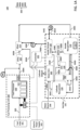
FIG. 1B is a detailed schematic view of thefuel processing unit 500 ofFIG. 1A having the first configuration, according to the first embodiment. It should be noted that thefuel processing unit 500 may include a fuel processing unit housing, such as a fuel processing cabinet (not shown) that houses thefuel processor 530. In that case, thethermal treatment device 510 may be located within the housing (internally) or outside of the housing (externally). - As illustrated in
FIG. 1B , thefuel processor 530 contains a processing material 534 (e.g., impurity conversion catalyst and/or impurity adsorbent material, etc.) for processing the fuel (e.g., removing impurities, such as sulfur or its compounds, from the fuel inlet stream) in thefuel line 505. Theprocessing material 534 in thefuel processor 530 may be located in one or moreprocessing material containers 532, such as desulfurization canisters. Theprocessing material 534 may be in a form of an adsorption bed, a catalyst coated support, a catalyst coating on the interior wall of thecontainer 532 and/or a catalyst bed. In one embodiment, theprocessing material 534 may be contained in a plurality of theprocessing material containers 532 fluidly connected in parallel or in series to thefuel line 505 and thefuel conduit 300A, as will be described in more detail below. - As illustrated in
FIGS. 1A and1B , thefuel processing unit 500 may also include athermal treatment device 510 for thermally treating (e.g., heating) at least one of the fuel in thefuel line 505 or theprocessing material 534 in thefuel processor 530 to an elevated temperature. In particular, thethermal treatment device 510 may thermally treat the fuel, theprocessing material 534 or both the fuel and theprocessing material 534. - The fuel from the
fuel inlet 301 may enter thefuel processing unit 500 through thefuel line 505 at ambient temperature (e.g., about 20°C to 45°C). Thethermal treatment device 510 may heat the fuel from about ambient temperature to an elevated temperature that increases at least one of a lifetime and/or efficiency of the processing material (e.g., desulfurization material) 534. The elevated temperature may greater than 50°C, for example from 55°C to 250°C, including from 60°C to 120°C. Thedesulfurization material 534 may, therefore, efficiently process the thermally treated fuel and produce a processed fuel that is substantially free of sulfur or its compounds. The processed fuel may then be transferred out of the processing material container (e.g., desulfurization canister) 532 to thefuel cell stack 102 through thefuel conduit 300A. - By operating the
fuel processor 530 at the elevated temperature instead of at ambient temperature, the lifespan of thedesulfurization material 534 may increase, such as double or triple. In addition, operating at the elevated temperature may increase a service life of thedesulfurization canister 532 and thus reduce the cost of servicing thefuel processing unit 500. Further, the cost of thedesulfurization material 534 may also be reduced, since it lasts longer, the cost of recycling the desulfurization material may also be reduced as the recycling frequency is decreased, and the cost of labor may also be reduced. - In the first embodiment of
FIGS. 1A and1B , thethermal treatment device 510 may include an electrically poweredthermal treatment device 510 powered by anelectric power supply 501. Theelectric power supply 501 may include a power supply which provides electric power generated outside the fuel cell system 100 (e.g., power supplied by the electric grid, battery, or other renewable energy source) and/or power generated by thefuel cell system 100. - The
thermal treatment device 510 may include, for example, an electric heater that generates heat by joule heating. The electric heater may include, for example, an insulated coil, jacket or plate resistor configured to heat thefuel line 505. The electric heater may contact thefuel line 505 or be placed in close proximity to thefuel line 505. - Alternatively, the
thermal treatment device 510 may comprise a gas heater, such as a natural gas, propane or a kerosine heater. The gas heater generates heat by oxidation of a fuel gas, such as natural gas, propane or kerosine. - The
fuel processing unit 500 may optionally also include a fuel analyzer 570 (FIG. 1 ) for analyzing the fuel in thefuel conduit 300A exiting thefuel processor 530. Thefuel analyzer 570 may include, for example, a gas composition analyzer, such as an optical or chemical gas composition sensor. A performance of the fuel processor 530 (e.g., an effectiveness of thefuel processor 530 in removing impurities, such as sulfur and/or its compounds) may be determined, for example, based on an analysis of the fuel composition performed by theanalyzer 570. - One or more operations in the
fuel processing unit 500 may be controlled by a dedicated controller of thefuel processing unit 500 and/or thecontroller 225 of thefuel cell system 100. Thecontroller 225 may be configured to control one or more operations offuel cell system 100, including one or more operations of thefuel processing unit 500. In particular, thecontroller 225 may control the amount of electric power provided by thepower supply 501 to theelectric heater 510 to control the temperature of the fuel in thefuel line 505 and/or the temperature of thefuel processor 530. Additionally, thecontroller 225 may control a flow rate of the fuel in thefuel line 505 from thefuel inlet 301 to thefuel processor 530. Thecontroller 225 may also control a flow rate of the fuel within thefuel processor 530. Thecontroller 225 may also operate the selection valve in thefuel processor 530 to provide automated selection of one or more of theprocessing material containers 532 in thefuel processor 530. - The
controller 225 may also control an operation of thefuel analyzer 570 in thefuel conduit 300A. Thecontroller 225 may receive a data signal from thefuel analyzer 570 and control an operation of thefuel processing unit 500 based on the data signal from thefuel analyzer 570. Thefuel processing unit 500 may include one or more temperature sensors (not shown) located in or near thefuel processing unit 500, such as in or on thefuel line 505, in thefuel processor 530 and/or in thefuel conduit 300A. Thecontroller 225 may receive a data signal from the temperature sensor(s) and control an operation of thefuel processing unit 500 based on the data signal from the temperature sensors, such as by controlling the temperature of thethermal treatment device 510 and thereby controlling a temperature of the fuel to be processed in thefuel processor 530 and/or a temperature of theprocessing material 534 in thefuel processor 530. In particular, thecontroller 225 may control an amount of heat produced by thethermal treatment device 510 by controlling a current or voltage of electric power from thepower supply 501 that powers thethermal treatment device 510. Thus, thecontroller 225 may control an operation of thethermal treatment device 510 based on the data signal from thefuel analyzer 570. Thecontroller 225 may also generate service indication signals based upon data signals provided from thefuel analyzer 570. For instance, based upon data signals received from thefuel analyzer 570, the controller may generate service indication signals which are provided to a remote monitoring control station for thefuel cell system 100 and used to schedule maintenance operations when the fuel analyzer data signals indicate gas impurities have increased above a threshold value. -
FIG. 2A is a schematic representation of thefuel cell system 100 having a second configuration, according to a second embodiment. The second configuration of thefuel cell system 100 may be substantially the same as the first configuration inFIG. 1A , except with respect to thethermal treatment device 510 and the manner of operating thethermal treatment device 510. - In the second configuration, the
thermal treatment device 510 may include a heat exchanger configured to heat the fuel in thefuel line 505, as shown inFIGS. 2A and2B . In particular, an elevated temperature heat exchange fluid is provided from other components of the fuel cell system to the heat exchanger (i.e., the thermal treatment device 510) to heat the fuel flowing through thefuel line 505. - The heat exchanger
thermal treatment device 510 may comprise any type of heat exchanger, such as a plate heat exchanger, a tube within a tube heat exchanger, a shell and tube heat exchanger, etc. In the second embodiment, the heat exchange fluid may include hot water and/or steam provided from thesteam generator 160 in thefuel cell system 100. As illustrated inFIG. 2A , the hot water and/or steam may be transferred from thesteam generator 160 to the heat exchangerthermal treatment device 510 bytransfer conduit 620a (e.g., a pipe). Thus, the transfer conduit connects an outlet of thesteam generator 160 to the heat exchangerthermal treatment device 510. Acontrol valve 660 may be included in thetransfer conduit 620a for controlling a flow rate of the hot water and/or steam in thetransfer conduit 620a. Thecontrol valve 660 may be controlled, for example, by a control signal from thecontroller 225. - The hot water and/or steam in the
transfer conduit 620a may enter the heat exchangerthermal treatment device 510 and heat the fuel in thefuel line 505 passing through the heat exchangerthermal treatment device 510. The hot water and/or steam may then exit the heat exchangerthermal treatment device 510 through areturn conduit 620b. Thereturn conduit 620b may provide the hot water and/or steam back to thewater conduit 306A for transporting water to thesteam generator 160. Alternatively, thereturn conduit 620b may provide the hot water and/or steam directly to thesteam generator 160. Thetransfer conduit 620a and returnconduit 620b may therefore constitute awater loop 670 connected to the heat exchangerthermal treatment device 510. - By controlling the
control valve 660, thecontroller 225 may control the temperature in the heat exchangerthermal treatment device 510 and thereby a temperature of the fuel in thefuel line 505. In particular, thecontroller 225 may increase a temperature of the fuel by opening thecontrol valve 660. Thecontroller 225 may decrease a temperature of the fuel by closing thecontrol valve 660. Further, thecontroller 225 may control thecontrol valve 660 based on a signal from thefuel analyzer 570. -
FIG. 3A is a schematic representation of thefuel cell system 100 having a third configuration, according to a third embodiment. The third configuration of thefuel cell system 100 may be substantially the same as the second configuration inFIG. 2A , except that afuel cell system 100 exhaust is used as the heat exchange fluid. - In the third configuration of
FIGS. 3A and3B , thethermal treatment device 510 may include a heat exchanger similar to the heat exchanger in the second configuration inFIGS. 2A and2B . However, in contrast to the second configuration, in the third configuration, the heat exchange fluid utilized by the heat exchangerthermal treatment device 510 may include a fuel cell exhaust from thefuel cell stack 102. In particular, the heat exchange fluid may include a cathode exhaust (i.e., theATO 130 exhaust) from thehot box 101. As illustrated inFIG. 3A , the cathode exhaust may be transferred from thecathode recuperator 120 in thehot box 101 by atransfer conduit 720a to the heat exchangerthermal treatment device 510. Thus, thetransfer conduit 720a fluidly connects an outlet of the anodetail gas oxidizer 130 to the heat exchangerthermal treatment device 510. The heat from the cathode exhaust may be transferred to the fuel in thethermal treatment device 510. The heat exchangerthermal treatment device 510 may comprise any type of heat exchanger, such as a finned tube heat exchanger, a plate heat exchanger, a tube within a tube heat exchanger, a shell and tube heat exchanger, etc. - As illustrated in
FIG. 3A , transferconduit 720a may be fluidly connected to thecathode recuperator 120 to receive at least a portion of the cathode exhaust from thecathode recuperator 120. Thecathode recuperator 120 receives the cathode exhaust (i.e., the ATO exhaust) from theATO 130. Thetransfer conduit 720a may alternatively and/or additionally be connected at other locations inside thehot box 101 for accessing the cathode exhaust produced by thefuel cell stack 102. For example, thetransfer conduit 720a may be coupled to the cathodeexhaust outlet conduit 304D provided from the steam generator 160 (if present). Alternatively, thetransfer conduit 720a may be coupled to theexhaust conduit 304A in order to access the cathode exhaust in theexhaust conduit 304A before it is used to oxidize the anode exhaust in theATO 130. - A
control valve 760 may be included in thetransfer conduit 720a for controlling a flow rate of the cathode exhaust in thetransfer conduit 720a. Thecontrol valve 760 may be controlled, for example, by a control signal from thecontroller 225. Similar to the second configuration inFIG. 2A , by controlling thecontrol valve 760, thecontroller 225 may control thethermal treatment device 510 and thereby a temperature of the fuel. Further, thecontroller 225 may control thecontrol valve 760 based on a signal from thefuel analyzer 570. - The cathode exhaust in the
transfer conduit 720a may enter the heat exchangerthermal treatment device 510 and heat the fuel in thefuel line 505 passing through the heat exchangerthermal treatment device 510. The cathode exhaust may then exit thethermal treatment device 510 throughexhaust conduit 720b. Theexhaust conduit 720b may transfer the cathode exhaust out of thefuel processing unit 500. -
FIG. 4 is a schematic representation of thefuel cell system 100 having a fourth configuration, according to a fourth embodiment. The fourth configuration of thefuel cell system 100 may be substantially the same as the first configuration inFIG. 1A , except that afuel pressurization device 810 is used as the thermal treatment device. - In the fourth configuration, the
fuel pressurization device 810, such as a fuel blower, is provided on thefuel line 505 upstream of thefuel processor 530. Thefuel pressurization device 810 increases the fuel temperature by increasing the fuel pressure. For example, natural gas at room temperature (e.g., 25 °C) and low pressure (e.g., 0.25 psi) may be heated to a higher temperature (e.g., 120 to 140 °C) by increasing the fuel pressure above 1 psi, such as from 8 to 10 psi by the fuel blower. Thus, in the fourth embodiment, thefuel pressurization device 810, such as the fuel blower, is located upstream of thefuel processor 530 to increase the fuel temperature to at least 50 °C by increasing a pressure of the fuel provided into the fuel processor. In this embodiment, the heater or heat exchangerthermal treatment device 510 may be present or omitted. - The
fuel pressurization device 810 may be controlled, for example, by a control signal from thecontroller 225. Similar to the previous configurations, by controlling the speed of the blower, thecontroller 225 may control a pressure and thus the temperature of the fuel. Further, thecontroller 225 may control the speed of the blower based on a signal from thefuel analyzer 570. -
FIG. 5 is a detailed schematic view of thefuel processing unit 500 having a fifth configuration, according to the fifth embodiment. The fifth configuration may be substantially similar to the first, second and third configurations shown inFIGS. 1B ,2B and3B , except that thefuel processor 530 may include a plurality ofdesulfurization canisters 532 and thefuel processing unit 500 may include coolingdevice 910 in addition to thethermal treatment device 510. - As illustrated in
FIG. 5 , in the fifth configuration, thefuel processor 530 may include afirst desulfurization canister 532a, asecond desulfurization canister 532b and athird desulfurization canister 532c, referred to collectively as thedesulfurization canisters 532. Thedesulfurization canisters 532 may be fluidly connected in series and include a plurality of respective different desulfurization materials 534 (e.g., 534a, 534b, 534c, etc.) configured to process the fuel at a plurality of different temperatures, respectively. - The
first desulfurization canister 532a may include afirst desulfurization material 534a configured to process the fuel at a first predetermined temperature. Thesecond desulfurization canister 532b may include asecond desulfurization material 534b configured to process the fuel at a second predetermined temperature. Thethird desulfurization canister 532c may include athird desulfurization material 534c configured to process the fuel at a third predetermined temperature. The first predetermined temperature, the second predetermined temperature and the third predetermined temperature may be different temperatures. - For example, the second predetermined temperature may comprise the above described elevated temperature, which is higher than the first predetermined temperature, while the third predetermined temperature may be lower than the second predetermined temperature and higher than the first predetermined temperature. The overall range of predetermined temperatures for the
desulfurization materials 534 in thedesulfurization canisters 532 in thefuel processor 530 may be in a range from 25°C to 120°C. Thus, for example, thedesulfurization material 534a in thedesulfurization canister 532a may operate most efficiently at around room temperature (e.g., 25°C), thedesulfurization material 534c in thedesulfurization canister 532c may operate most efficiently at 40°C, and thedesulfurization material 534b in thedesulfurization canister 532b may operate most efficiently at the elevated temperature between 60°C and 120°C, and so on. - The
fuel processing unit 500 may also include thethermal treatment device 510 and thecooling device 910. Thethermal treatment device 510 may be configured to heat the fuel to the elevated second predetermined temperature, and thecooling device 910 may be configured to actively cool the fuel to the third predetermined temperature. As used herein, actively cool means providing cooling air or another cooling medium to cool the fuel (e.g., by convection and/or conduction) in addition to passively cooling the fuel as it passes throughvarious desulfurizer canisters 532 and thefuel line 505 which are maintained at a lower temperature than the fuel. - The
thermal treatment device 510 may comprise the heater of the first embodiment or the heat exchanger of the second or third embodiments. Thecooling device 910 may comprise any suitable cooling device, such as a cooling fan or a heat exchanger. - The
first desulfurization canister 532a may be located upstream of thesecond desulfurization canister 532b and thethird desulfurization canister 532c. Thefirst desulfurization canister 532a may include anambient desulfurization material 534a configured to process the fuel most efficiently at an ambient temperature (e.g., about 20°C to 35°C). Therefore, the fuel may be transferred in thefuel line 505 to thedesulfurization canister 532a at ambient temperature without being thermally treated by a thermal treatment device. - The processed fuel may be transferred from the
first desulfurization canister 532a to thesecond desulfurization canister 532b via a first connectingportion 505a of thefuel line 505. Thesecond desulfurization canister 532b may include an elevated temperature desulfurization material configured to process the fuel most efficiently at the elevated temperature above 50°C. In at least one embodiment, the desulfurization material may be configured to process the fuel most efficiently at a temperature in a range from 60°C to 120°C. - The
fuel processor 530 includes thethermal treatment device 510 on the first connectingportion 505a of thefuel line 505 located between thefirst desulfurization canister 532a and thesecond desulfurization canister 532b. Thethermal treatment device 510 may thermally treat the fuel before the fuel enters thesecond desulfurization canister 532b so that the fuel enters thesecond desulfurization canister 532b at the elevated second predetermined temperature. - In one embodiment, the
thermal treatment device 510 is a heat exchanger that heats the fuel in the first connectingportion 505a of thefuel line 505 with a hot (e.g., greater than ambient temperature) heat exchange fluid. The heat exchange fluid may include, for example, hot water, steam, exhaust from thefuel cell stack 102, etc., as described above with respect toFIGS. 2B and3B . The heat exchanger may be coupled to a heatexchange fluid inlet 920a which transfers the heat exchange fluid to the heat exchanger, and coupled to a heatexchange fluid outlet 920b which transfers the heat exchange fluid away from the heat exchanger. The heatexchange fluid inlet 920a may comprise one of theconduits FIGS. 2A and3A , respectively. The heatexchange fluid outlet 920b may comprise one of theconduits FIGS. 2A and3A , respectively. Alternatively, thethermal treatment device 510 may comprise an electric heater that generates heat by joule heating, as illustrated inFIGs. 1A and1B (in which case the heat exchange fluid inlets and fluid outlets inFIG. 5 can be eliminated). - The fuel may be transferred by the second connecting
portion 505b of thefuel line 505 from thesecond desulfurization canister 532b to thethird desulfurization canister 532c. Thethird desulfurization canister 532c may include an intermediatetemperature desulfurization material 534c configured to process the fuel most efficiently at an intermediate temperature in a range from 35°C to 45°C. - The
fuel processor 530 includes thecooling device 910 on the second connectingportion 505b of thefuel line 505 which fluidly connects thesecond desulfurization canister 532b to thethird desulfurization canister 532c. Thecooling device 910 may actively cool the fuel before the fuel enters thethird desulfurization canister 532c so that the fuel enters thethird desulfurization canister 532c at the third predetermined temperature (e.g., a temperature in a range from 35°C to 45°C). In one embodiment, thecooling device 910 is an electric fan powered by thepower supply 501. Theelectric power supply 501 may include a power supply which provides electric power generated outside the fuel cell system 100 (e.g., power supplied by the electric grid, battery, or other renewable energy source) and/or power generated by thefuel cell system 100. - The fan cools the fuel in the second connecting
portion 505b of thefuel line 505 by blowing ambient air over the second connectingportion 505b of thefuel line 505. Alternatively or additionally, thecooling device 910 may be a heat exchanger that uses a cool heat exchange fluid (e.g., cold water) to cool the fuel in the second connectingportion 505b of thefuel line 505. For example, the heat exchanger may be connected to thewater conduit 306A in a cooling loop which provides cold water from thewater conduit 306A to the heat exchanger. - In various embodiments, the
same desulfurization material 534 may be operated at different elevated temperatures at the beginning and middle of its lifetime. For example, the elevated temperature comprises a first predetermined temperature (e.g., 55°C to 70 °C) during at least a first six months (or during 1 to 2 years) from a beginning of lifetime of thedesulfurization material 534. Then, the elevated temperature comprises a second predetermined temperature (e.g., 110°C to 125°C) higher than the first predetermined temperature after the at least a first six months (or after 1 to 2 years) from the beginning of lifetime of the desulfurization material. - While particular configurations have been discussed in connection with the disclosure of
FIG. 5 , it should be understood that heat exchange embodiments fromFIGs. 1-4 can be utilized to heat thedesulfurization canisters 532 in different orders and in different combinations. For example,desulfurization canister 532a can be configured to operate at ambient temperature as illustrated inFIG. 5 , anddesulfurization canister 532b can be configured to operate at an elevated temperature compared todesulfurization canister 532a through the use of an electric heater as illustrated and described in connection withFIG. 1B . Finally,desulfurization canister 532c can be configured to operate at a temperature greater thandesulfurization canister 532b through the use of a cathode exhaust supplied to a heat exchangerthermal treatment device 510 as illustrated inFIG. 3A . - The foregoing method descriptions are provided merely as illustrative examples and are not intended to require or imply that the steps of the various embodiments must be performed in the order presented. As will be appreciated by one of skill in the art, the order of steps in the foregoing embodiments may be performed in any order. Words such as "thereafter," "then," "next," etc. are not necessarily intended to limit the order of the steps; these words may be used to guide the reader through the description of the methods. Further, any reference to claim elements in the singular, for example, using the articles "a," "an" or "the" is not to be construed as limiting the element to the singular. Further, any step or component of any embodiment described herein can be used in any other embodiment.
- The preceding description of the disclosed aspects is provided to enable any person skilled in the art to make or use the present invention. Various modifications to these aspects will be readily apparent to those skilled in the art, and the generic principles defined herein may be applied to other aspects without departing from the scope of the invention. Thus, the present invention is not intended to be limited to the aspects shown herein but is to be accorded the widest scope consistent with the principles and novel features disclosed herein.
- The invention also refers to the following embodiments, wherein the term "claim" means "embodiment":
- 1. A fuel processing unit, comprising:
- a fuel line configured to transfer a fuel;
- a fuel processor containing a processing material container configured to contain a processing material, the fuel processor configured to remove at least one impurity from the fuel at an elevated temperature above 50°C to produce a processed fuel; and
- a thermal treatment device configured to thermally treat the fuel by treating at least one of the fuel line to at least the elevated temperature or the processing material container to at least the elevated temperature.
- 2. The fuel processing unit of
claim 1, wherein the thermal treatment device comprises a heater. - 3. The fuel processing unit of claim 2, wherein the heater is located on or adjacent to the fuel line and is configured to thermally treat the fuel by heating the fuel line.
- 4. The fuel processing unit of claim 2, wherein the heater is located on or adjacent to the processing material container and is configured to thermally treat the processing material by heating the processing material container.
- 5. The fuel processing unit of
claim 1, wherein the thermal treatment device comprises a heat exchanger. - 6. The fuel processing unit of claim 5, wherein the heat exchanger is located on the fuel line.
- 7. The fuel processing unit of
claim 1, wherein the thermal treatment device comprises a fuel pressurization device located on the fuel line. - 8. The fuel processing unit of
claim 1, wherein:- the processing material container comprises a first desulfurization canister;
- the processing material comprises a first desulfurization material configured to remove sulfur from the fuel at the elevated temperature; and
- the elevated temperature is 60°C to 120°C.
- 9. The fuel processing unit of claim 8, wherein the fuel processor further comprises:
- a second desulfurization canister located on the fuel line upstream of the first desulfurization canister, the second desulfurization including a second desulfurization material configured to remove the sulfur from the fuel at a second temperature below the elevated temperature;
- a third desulfurization canister located on the fuel line downstream of the first desulfurization canister, the third desulfurization including a third desulfurization material configured to remove the sulfur from the fuel at a third temperature below the elevated temperature; and
- a cooling device located on a second connecting portion of the fuel line which connects the first desulfurization canister and the third desulfurization canister, wherein the thermal treatment device is located on a first connecting portion of the fuel line which connects the first desulfurization canister and the second desulfurization canister.
- 10. A fuel cell system, comprising:
- the fuel processing unit of
claim 1; - a fuel cell stack; and
- at least one fuel conduit connecting an outlet of the fuel processing unit to a fuel inlet of the fuel cell stack.
- the fuel processing unit of
- 11. The fuel cell system of claim 10, further comprising:
- a steam generator; and
- a transfer conduit connecting an outlet of the steam generator to the thermal treatment device, wherein the thermal treatment device comprises a heat exchanger located on the fuel line.
- 12. The fuel cell system of claim 10, further comprising:
- an anode tail gas oxidizer configured to oxidize a fuel exhaust from the fuel cell stack using an air exhaust from the fuel cell stack; and
- a transfer conduit fluidly connecting an outlet of the anode tail gas oxidizer to the thermal treatment device, wherein the thermal treatment device comprises a heat exchanger located on the fuel line.
- 13. A method of operating a fuel cell system, comprising:
- processing a fuel to remove at least one impurity from the fuel at an elevated temperature above 50°C to provide a processed fuel; and
- providing the processed fuel to a fuel cell stack.
- 14. The method of claim 13, wherein the processing the fuel to remove at least one impurity from the fuel comprises desulfurizing the fuel to remove at least one of sulfur or a sulfur compound from the fuel using a desulfurization material.
- 15. The method of claim 14, wherein the processing the fuel to remove at least one impurity from the fuel at the elevated temperature comprises heating the fuel to at least the elevated temperature prior to providing the fuel to the desulfurization material.
- 16. The method of claim 15, wherein the heating the fuel comprises using a heater to heat the fuel.
- 17. The method of claim 15, wherein the heating the fuel comprises heating the fuel in a heat exchanger using at least one of steam or a cathode exhaust stream from the fuel cell stack.
- 18. The method of claim 15, wherein the heating the fuel comprises increasing a pressure of the fuel to increase a temperature of the fuel to the elevated temperature above 50°C.
- 19. The method of claim 15, further comprising:
- actively cooling the processed fuel; and
- providing the cooled processed fuel to a second desulfurizer material prior to the providing the processed fuel to the fuel cell stack.
- 20. The method of claim 14, wherein:
- the elevated temperature comprises a first predetermined temperature during at least a first six months from a beginning of lifetime of the desulfurization material; and
- the elevated temperature comprises a second predetermined temperature higher than the first predetermined temperature after the at least a first six months from the beginning of lifetime of the desulfurization material.
Claims (15)
- A fuel processing unit, comprising:a fuel line configured to transfer a fuel;a fuel processor containing a processing material container configured to contain a processing material, the fuel processor configured to remove at least one impurity from the fuel at an elevated temperature above 50°C to produce a processed fuel; anda thermal treatment device configured to thermally treat the fuel by treating at least one of the fuel line to at least the elevated temperature or the processing material container to at least the elevated temperature.
- The fuel processing unit of claim 1, wherein the thermal treatment device comprises a heater.
- The fuel processing unit of claim 2, wherein the heater is located either:on or adjacent to the fuel line and is configured to thermally treat the fuel by heating the fuel line; oron or adjacent to the processing material container and is configured to thermally treat the processing material by heating the processing material container.
- The fuel processing unit of claim 1, wherein the thermal treatment device comprises a heat exchanger located on the fuel line.
- The fuel processing unit of claim 1, wherein the thermal treatment device comprises a fuel pressurization device located on the fuel line.
- The fuel processing unit of claim 1, wherein:the processing material container comprises a first desulfurization canister;the processing material comprises a first desulfurization material configured to remove sulfur from the fuel at the elevated temperature;the elevated temperature is 60°C to 120°C;the fuel processor further comprises:a second desulfurization canister located on the fuel line upstream of the first desulfurization canister, the second desulfurization including a second desulfurization material configured to remove the sulfur from the fuel at a second temperature below the elevated temperature;a third desulfurization canister located on the fuel line downstream of the first desulfurization canister, the third desulfurization including a third desulfurization material configured to remove the sulfur from the fuel at a third temperature below the elevated temperature; anda cooling device located on a second connecting portion of the fuel line which connects the first desulfurization canister and the third desulfurization canister, wherein the thermal treatment device is located on a first connecting portion of the fuel line which connects the first desulfurization canister and the second desulfurization canister.
- A fuel cell system, comprising:the fuel processing unit of claim 1;a fuel cell stack; andat least one fuel conduit connecting an outlet of the fuel processing unit to a fuel inlet of the fuel cell stack.
- The fuel cell system of claim 7, further comprising:at least one of a steam generator or an anode tail gas oxidizer configured to oxidize a fuel exhaust from the fuel cell stack using an air exhaust from the fuel cell stack; anda transfer conduit connecting an outlet of the steam generator or the anode tail gas oxidizer to the thermal treatment device, wherein the thermal treatment device comprises a heat exchanger located on the fuel line.
- A method of operating a fuel cell system, comprising:processing a fuel to remove at least one impurity from the fuel at an elevated temperature above 50°C to provide a processed fuel; andproviding the processed fuel to a fuel cell stack.
- The method of claim 9, wherein the processing the fuel to remove at least one impurity from the fuel comprises desulfurizing the fuel to remove at least one of sulfur or a sulfur compound from the fuel using a desulfurization material.
- The method of claim 10, wherein the processing the fuel to remove at least one impurity from the fuel at the elevated temperature comprises heating the fuel to at least the elevated temperature prior to providing the fuel to the desulfurization material.
- The method of claim 11, wherein the heating the fuel comprises using a heater to heat the fuel.
- The method of claim 11, wherein the heating the fuel comprises heating the fuel in a heat exchanger using at least one of steam or a cathode exhaust stream from the fuel cell stack.
- The method of claim 11, wherein the heating the fuel comprises increasing a pressure of the fuel to increase a temperature of the fuel to the elevated temperature above 50°C.
- The method of claim 11, further comprising:actively cooling the processed fuel; andproviding the cooled processed fuel to a second desulfurizer material prior to the providing the processed fuel to the fuel cell stack;wherein:the elevated temperature comprises a first predetermined temperature during at least a first six months from a beginning of lifetime of the desulfurization material; andthe elevated temperature comprises a second predetermined temperature higher than the first predetermined temperature after the at least a first six months from the beginning of lifetime of the desulfurization material.
Applications Claiming Priority (1)
| Application Number | Priority Date | Filing Date | Title |
|---|---|---|---|
| US202363526295P | 2023-07-12 | 2023-07-12 |
Publications (2)
| Publication Number | Publication Date |
|---|---|
| EP4492509A2 true EP4492509A2 (en) | 2025-01-15 |
| EP4492509A3 EP4492509A3 (en) | 2025-02-26 |
Family
ID=91738843
Family Applications (1)
| Application Number | Title | Priority Date | Filing Date |
|---|---|---|---|
| EP24185342.3A Pending EP4492509A3 (en) | 2023-07-12 | 2024-06-28 | Fuel processing unit for a fuel cell system and method of operating thereof at an elevated temperature |
Country Status (3)
| Country | Link |
|---|---|
| US (1) | US20250023076A1 (en) |
| EP (1) | EP4492509A3 (en) |
| KR (1) | KR20250010532A (en) |
Citations (1)
| Publication number | Priority date | Publication date | Assignee | Title |
|---|---|---|---|---|
| US11196068B2 (en) | 2019-01-29 | 2021-12-07 | Bloom Energy Corporation | Fuel cell system containing water injector and method of operating the same |
Family Cites Families (3)
| Publication number | Priority date | Publication date | Assignee | Title |
|---|---|---|---|---|
| US7063732B2 (en) * | 2003-07-28 | 2006-06-20 | Fuelcell Energy, Inc. | High-capacity sulfur adsorbent bed and gas desulfurization method |
| DE112017002018T5 (en) * | 2016-04-13 | 2019-01-03 | Lg Fuel Cell Systems, Inc. | Fuel cell system with combined passive and active sorbent beds |
| US10847824B2 (en) * | 2018-09-13 | 2020-11-24 | Bloom Energy Corporation | Fuel cell system including high-temperature desulfurization subsystem and method of operating the same |
-
2024
- 2024-06-28 EP EP24185342.3A patent/EP4492509A3/en active Pending
- 2024-06-28 US US18/759,293 patent/US20250023076A1/en active Pending
- 2024-06-28 KR KR1020240085059A patent/KR20250010532A/en active Pending
Patent Citations (1)
| Publication number | Priority date | Publication date | Assignee | Title |
|---|---|---|---|---|
| US11196068B2 (en) | 2019-01-29 | 2021-12-07 | Bloom Energy Corporation | Fuel cell system containing water injector and method of operating the same |
Also Published As
| Publication number | Publication date |
|---|---|
| US20250023076A1 (en) | 2025-01-16 |
| EP4492509A3 (en) | 2025-02-26 |
| KR20250010532A (en) | 2025-01-21 |
Similar Documents
| Publication | Publication Date | Title |
|---|---|---|
| US8790840B2 (en) | Systems and methods for fuel cell thermal management | |
| St-Pierre et al. | Fuel cells: a new, efficient and cleaner power source | |
| JP4515253B2 (en) | Fuel cell system | |
| US8227119B2 (en) | Fuel cell system | |
| US12542289B2 (en) | Handling of variable and unpredictable gas composition changes to maximize health and performance of fuel cell systems | |
| US20250243053A1 (en) | Systems and methods of processing ammonia | |
| KR102044766B1 (en) | High Efficiency Fuel Cell System Improved Thermal Efficiency and Performance of the Maintenance | |
| EP1929568B1 (en) | Fuel cell stacks and systems with fluid-responsive temperature regulation | |
| KR102355412B1 (en) | Fuel cell system and ship having the same | |
| US20260005272A1 (en) | Fuel cell system containing catalyst based fuel contamination sensor and method of operating thereof | |
| EP4492509A2 (en) | Fuel processing unit for a fuel cell system and method of operating thereof at an elevated temperature | |
| US11081704B2 (en) | Fuel cell systems containing chromium filters | |
| US12126061B1 (en) | Ammonia-based solid oxide fuel cell (SOFC) system in which temperature rise using heating element is applied, and operation method therefor | |
| KR101817432B1 (en) | Fuel cell system | |
| CN103210536A (en) | Method and apparatus for avoiding anodic oxidation | |
| WO2008016217A1 (en) | Fuel cell system | |
| US20240347749A1 (en) | Fuel cell system including anode recycle cooler and method of operating the same | |
| US20260128336A1 (en) | Handling of variable and unpredictable gas composition changes to maximize health and performance of fuel cell systems | |
| JP2010225284A (en) | Operation method of indirect internal reforming type solid oxide fuel cell system | |
| JP2011175745A (en) | Fuel cell system | |
| KR101435392B1 (en) | Fuel cell system | |
| KR101435391B1 (en) | Fuel cell system | |
| WO2012091131A1 (en) | Fuel cell system | |
| WO2009123585A1 (en) | Fuel processing system for a fuel cell power plant | |
| WO2012091132A1 (en) | Fuel cell system |
Legal Events
| Date | Code | Title | Description |
|---|---|---|---|
| PUAI | Public reference made under article 153(3) epc to a published international application that has entered the european phase |
Free format text: ORIGINAL CODE: 0009012 |
|
| STAA | Information on the status of an ep patent application or granted ep patent |
Free format text: STATUS: THE APPLICATION HAS BEEN PUBLISHED |
|
| AK | Designated contracting states |
Kind code of ref document: A2 Designated state(s): AL AT BE BG CH CY CZ DE DK EE ES FI FR GB GR HR HU IE IS IT LI LT LU LV MC ME MK MT NL NO PL PT RO RS SE SI SK SM TR |
|
| PUAL | Search report despatched |
Free format text: ORIGINAL CODE: 0009013 |
|
| AK | Designated contracting states |
Kind code of ref document: A3 Designated state(s): AL AT BE BG CH CY CZ DE DK EE ES FI FR GB GR HR HU IE IS IT LI LT LU LV MC ME MK MT NL NO PL PT RO RS SE SI SK SM TR |
|
| RIC1 | Information provided on ipc code assigned before grant |
Ipc: H01M 8/04701 20160101ALI20250122BHEP Ipc: H01M 8/04111 20160101ALI20250122BHEP Ipc: H01M 8/04007 20160101ALI20250122BHEP Ipc: H01M 8/04029 20160101ALI20250122BHEP Ipc: H01M 8/0662 20160101ALI20250122BHEP Ipc: H01M 8/0612 20160101ALI20250122BHEP Ipc: H01M 8/04014 20160101AFI20250122BHEP |
|
| STAA | Information on the status of an ep patent application or granted ep patent |
Free format text: STATUS: REQUEST FOR EXAMINATION WAS MADE |
|
| 17P | Request for examination filed |
Effective date: 20250820 |