EP4492414A1 - Bobbin structure and electromagnetic coil - Google Patents
Bobbin structure and electromagnetic coil Download PDFInfo
- Publication number
- EP4492414A1 EP4492414A1 EP23784202.6A EP23784202A EP4492414A1 EP 4492414 A1 EP4492414 A1 EP 4492414A1 EP 23784202 A EP23784202 A EP 23784202A EP 4492414 A1 EP4492414 A1 EP 4492414A1
- Authority
- EP
- European Patent Office
- Prior art keywords
- recess
- bobbin
- mounting
- protrusion
- section
- Prior art date
- Legal status (The legal status is an assumption and is not a legal conclusion. Google has not performed a legal analysis and makes no representation as to the accuracy of the status listed.)
- Pending
Links
Images


Classifications
-
- H—ELECTRICITY
- H01—ELECTRIC ELEMENTS
- H01F—MAGNETS; INDUCTANCES; TRANSFORMERS; SELECTION OF MATERIALS FOR THEIR MAGNETIC PROPERTIES
- H01F5/00—Coils
- H01F5/02—Coils wound on non-magnetic supports, e.g. formers
-
- H—ELECTRICITY
- H01—ELECTRIC ELEMENTS
- H01F—MAGNETS; INDUCTANCES; TRANSFORMERS; SELECTION OF MATERIALS FOR THEIR MAGNETIC PROPERTIES
- H01F27/00—Details of transformers or inductances, in general
- H01F27/28—Coils; Windings; Conductive connections
- H01F27/29—Terminals; Tapping arrangements for signal inductances
-
- H—ELECTRICITY
- H01—ELECTRIC ELEMENTS
- H01F—MAGNETS; INDUCTANCES; TRANSFORMERS; SELECTION OF MATERIALS FOR THEIR MAGNETIC PROPERTIES
- H01F27/00—Details of transformers or inductances, in general
- H01F27/28—Coils; Windings; Conductive connections
- H01F27/30—Fastening or clamping coils, windings, or parts thereof together; Fastening or mounting coils or windings on core, casing, or other support
-
- H—ELECTRICITY
- H01—ELECTRIC ELEMENTS
- H01F—MAGNETS; INDUCTANCES; TRANSFORMERS; SELECTION OF MATERIALS FOR THEIR MAGNETIC PROPERTIES
- H01F27/00—Details of transformers or inductances, in general
- H01F27/28—Coils; Windings; Conductive connections
- H01F27/30—Fastening or clamping coils, windings, or parts thereof together; Fastening or mounting coils or windings on core, casing, or other support
- H01F27/306—Fastening or mounting coils or windings on core, casing or other support
-
- H—ELECTRICITY
- H01—ELECTRIC ELEMENTS
- H01F—MAGNETS; INDUCTANCES; TRANSFORMERS; SELECTION OF MATERIALS FOR THEIR MAGNETIC PROPERTIES
- H01F27/00—Details of transformers or inductances, in general
- H01F27/28—Coils; Windings; Conductive connections
- H01F27/32—Insulating of coils, windings, or parts thereof
-
- H—ELECTRICITY
- H01—ELECTRIC ELEMENTS
- H01F—MAGNETS; INDUCTANCES; TRANSFORMERS; SELECTION OF MATERIALS FOR THEIR MAGNETIC PROPERTIES
- H01F27/00—Details of transformers or inductances, in general
- H01F27/28—Coils; Windings; Conductive connections
- H01F27/32—Insulating of coils, windings, or parts thereof
- H01F27/324—Insulation between coil and core, between different winding sections, around the coil; Other insulation structures
-
- H—ELECTRICITY
- H01—ELECTRIC ELEMENTS
- H01F—MAGNETS; INDUCTANCES; TRANSFORMERS; SELECTION OF MATERIALS FOR THEIR MAGNETIC PROPERTIES
- H01F27/00—Details of transformers or inductances, in general
- H01F27/28—Coils; Windings; Conductive connections
- H01F27/32—Insulating of coils, windings, or parts thereof
- H01F27/324—Insulation between coil and core, between different winding sections, around the coil; Other insulation structures
- H01F27/325—Coil bobbins
-
- H—ELECTRICITY
- H01—ELECTRIC ELEMENTS
- H01F—MAGNETS; INDUCTANCES; TRANSFORMERS; SELECTION OF MATERIALS FOR THEIR MAGNETIC PROPERTIES
- H01F5/00—Coils
Definitions
- the invention relates to a technical field of electromagnetic coils, and specifically relates to a bobbin structure and an electromagnetic coil.
- insulation performance is the most basic and most critical safety performance indicator.
- the overall wall thickness of the part of a structure where a grounding plug of the electromagnetic coil and a bobbin are mounted is less than the other 2/3 of a platform of a jaw-shaped part, and the injection molding amount is small, which easily makes the insulation performance of the electromagnetic coil not good enough and causes the breakdown phenomenon, thereby resulting in poor encapsulation effect of a plastic sealing encapsulation layer.
- the existing bobbin is easily separated from a magnetic conductive frame, which may also cause the problem of poor insulation performance of the electromagnetic coil.
- a main objective of the present invention is to provide a bobbin structure and an electromagnetic coil to solve the problem in the art known to inventors of poor insulation performance of the electromagnetic coil.
- a bobbin structure including a first bobbin section.
- the first bobbin section includes first mounting protrusions and a mounting recess, the first mounting protrusions being located in the mounting recess, and the first mounting protrusions being configured to support a grounding tab.
- the first bobbin section further includes a first recess.
- the mounting recess is formed in a bottom wall of the first recess, so that plastic material flows from the first recess to the mounting recess for plastic sealing.
- an end of the first recess extends to an outer periphery of the first bobbin section, and the other end of the first recess extends toward the middle of the first bobbin section.
- the first bobbin section further includes a guide groove.
- the guide groove is communicated with the first recess, and the guide groove is disposed on an outer side of the first recess, so that the plastic material flows from the guide groove to the first recess.
- a plurality of guide grooves are provided, and the plurality of guide grooves are arranged around the first recess.
- two guide grooves are provided, and the two guide grooves are respectively arranged on two opposite ends of the first recess.
- the depth of the guide groove gradually increases in a direction close to the first recess, and the maximum depth of the guide groove is less than or equal to the minimum depth of the first recess.
- the first bobbin section further includes a plurality of first limiting protrusions. Two opposite sides of the first mounting protrusion are each provided with at least one first limiting protrusion to limit the grounding tab in a width direction of the grounding tab.
- a plurality of first limiting protrusions are disposed on both sides of the first mounting protrusion, and the plurality of first limiting protrusions located on one side of the first mounting protrusion are arranged at intervals in an extension direction of the grounding tab.
- a plurality of first mounting protrusions are provided, and the plurality of first mounting protrusions are arranged at intervals in the extension direction of the grounding tab.
- the first bobbin section includes an annular protrusion.
- the annular protrusion protrudes from an outer surface of the first bobbin section, and a second recess is formed in the annular protrusion, so that after a magnetic conductive frame is placed on the first bobbin section, the plastic material fills the second recess for plastic sealing; and/or, one end of the first recess extends to the outer periphery of the first bobbin section, and the other end of the first recess extends to the annular protrusion.
- the depth of the second recess is less than the depth of the first recess, so that a first step is formed between the second recess and the first recess.
- the bobbin structure further includes a second mounting protrusion.
- the second mounting protrusion is arranged in the first recess, or the second mounting protrusion is configured to enclose the first recess, so that a magnetic conductive frame is supported by the second mounting protrusion.
- the second mounting protrusion is an L-shaped structure formed by a first protrusion section and a second protrusion section, and a free end of the first protrusion section extends toward the first mounting protrusion.
- the first bobbin section further includes two second limiting protrusions.
- the two second limiting protrusions are respectively arranged on two opposite ends of the first recess, so that a magnetic conductive frame is limited by the two limiting protrusions.
- an electromagnetic coil including a bobbin structure.
- the bobbin structure is the above bobbin structure.
- the bobbin structure of the present invention includes the first bobbin section.
- the first bobbin section includes the first mounting protrusions and the mounting recess, the first mounting protrusions being located in the mounting recess, and the first mounting protrusions being configured to support the grounding tab.
- the first bobbin section further includes the first recess.
- the mounting recess is formed in the bottom wall of the first recess, so that the plastic material flows from the first recess to the mounting recess for plastic sealing.
- the first recess is added, and the mounting recess is formed in the bottom wall of the first recess, so that in an injection molding process, the plastic material flows from the first recess to the mounting recess and fills the first recess, thereby increasing the injection molding amount, increasing the injection molding thickness, and improving the insulation performance.
- the present invention provides a bobbin structure.
- the bobbin structure includes a first bobbin section 1.
- the first bobbin section 1 includes first mounting protrusions 101 and a mounting recess 102, the first mounting protrusions 101 being located in the mounting recess 102, and the first mounting protrusions 101 being configured to support a grounding tab 100.
- the first bobbin section 1 further includes a first recess 10.
- the mounting recess 102 is formed in a bottom wall of the first recess 10, so that plastic material flows from the first recess 10 to the mounting recess 102 for plastic sealing.
- the bobbin structure of the present invention includes the first bobbin section 1.
- the first bobbin section 1 includes the first mounting protrusions 101 and the mounting recess 102, the first mounting protrusions 101 being located in the mounting recess 102, and the first mounting protrusions 101 being configured to support the grounding tab 100.
- the first bobbin section 1 further includes the first recess 10.
- the mounting recess 102 is formed in the bottom wall of the first recess 10, so that the plastic material flows from the first recess 10 to the mounting recess 102 for plastic sealing.
- the first recess 10 is added, and the mounting recess 102 is formed in the bottom wall of the first recess 10, so that in an injection molding process, the plastic material flows from the first recess 10 to the mounting recess 102 and fills the first recess 10, thereby increasing the injection molding amount, increasing the injection molding thickness, and improving the insulation performance.
- plastic material in the present invention is a Bulk Molding Compound (BMC).
- one end of the first recess 10 extends to the outer periphery of the first bobbin section 1, and the other end of the first recess 10 extends toward the middle of the first bobbin section 1.
- a recess gap is formed between the first mounting protrusion 101 and the mounting recess 102.
- the first bobbin section 1 further includes a guide groove 20.
- the guide groove 20 is communicated with the first recess 10, and the guide groove 20 is arranged on an outer side of the first recess 10, so that the plastic material flows from the guide groove 20 to the first recess 10.
- a plurality of guide grooves 20 are provided, and the plurality of guide grooves 20 are arranged around the first recess 10.
- two guide grooves 20 are provided, and the two guide grooves 20 are respectively arranged on two opposite ends of the first recess 10.
- the guide grooves 20 are polygonal.
- the guide grooves 20 are quadrilateral, and the guide grooves 20 are of a strip-shaped structure.
- the depth of the guide groove 20 gradually increases in a direction close to the first recess 10, so that the plastic material may flow in a direction toward the first recess 10.
- the maximum depth of the guide groove 20 is less than the minimum depth of the first recess 10, so that a step is formed between the guide groove 20 and the first recess 10; or the maximum depth of the guide groove 20 is equal to the minimum depth of the first recess 10, so that a smooth transition is formed between the guide groove 20 and the first recess 10.
- the first bobbin section 1 further includes a plurality of first limiting protrusions 103. Two opposite sides of the first mounting protrusion 101 are each provided with at least one first limiting protrusion 103 to limit the grounding tab 100 in a width direction of the grounding tab 100.
- both sides of the first mounting protrusion 101 are each provided with the plurality of first limiting protrusions 103, and the plurality of first limiting protrusions 103 located on one side of the first mounting protrusion 101 are arranged at intervals in an extension direction of the grounding tab 100.
- a plurality of first mounting protrusions 101 are provided, and the plurality of first mounting protrusions 101 are arranged at intervals in the extension direction of the grounding tab 100.
- the mounting recess 102 is formed between the two adjacent first mounting protrusions 101, so that the plastic material flows to the mounting recess 102 at the outer periphery of the first mounting protrusion 101, and also flows through the mounting recess 102 between the two adjacent first mounting protrusions 101, and the plurality of first limiting protrusions 103 are arranged at intervals in the extension direction of the grounding tab 100, so that the plastic material flows through the recess gap between the two adjacent first limiting protrusions 103, so that the amount of a plastic sealing material (BMC) of the grounding tab 100 is increased.
- BMC plastic sealing material
- the grounding tab 100 includes a third limiting protrusion 110.
- the third limiting protrusion 110 is located on one side, close to the first mounting protrusion 101, of the grounding tab 100, and the third limiting protrusion 110 is configured to limit a magnetic conductive frame 200.
- the first bobbin section 1 includes an annular protrusion 104.
- the annular protrusion 104 protrudes from an outer surface of the first bobbin section 1, and a second recess 30 is formed in the annular protrusion 104, so that after the magnetic conductive frame 200 is placed on the first bobbin section 1, the plastic material fills the second recess 30 for plastic sealing.
- the magnetic conductive frame 200 and the second recess 30 are fixedly connected by injection molding to prevent the magnetic conductive frame from falling off; and/or one end of the first recess 10 extends to the outer periphery of the first bobbin section 1, and the other end of the first recess 10 extends to the annular protrusion 104.
- the second groove 30 is of a strip-shaped structure.
- the depth of the second recess 30 is less than that of the first recess 10, so that a first step is formed between the second recess 30 and the first recess 10.
- the bobbin structure further includes second mounting protrusions 40.
- the second mounting protrusions 40 are arranged in the first recess 10, or the second mounting protrusions 40 are configured to enclose the first recess 10, so as to support the magnetic conductive frame 200 through the second mounting protrusions 40.
- the second mounting protrusion 40 is of an L-shaped structure composed of a first protrusion section 41 and a second protrusion section 42, and a free end of the first protrusion section 41 extends toward the first mounting protrusion 101.
- the first protrusion section 41 is configured to support the magnetic conductive frame 200, and the plastic material fills the first recess 10 between the second protrusion section 42 and the first limiting protrusion 103, so that the magnetic conductive frame 200 and the first recess 10 here are fixedly connected by injection molding, thereby further preventing the magnetic conductive frame 200 from falling off.
- two second mounting protrusions 40 are provided, and the two second mounting protrusions 40 are respectively arranged on the sides, away from the first mounting protrusion 101, of the first limiting protrusions 103, and the second mounting protrusions 40 and the first limiting protrusions 103 are arranged at intervals to allow the plastic material to flow through and fill the first recess 10 between the second mounting protrusions 40 and the first limiting protrusions 103.
- the first bobbin section further includes two second limiting protrusions 50.
- the two second limiting protrusions 50 are respectively arranged on two opposite ends of the first recess 10, so as to limit the magnetic conductive frame 200 through the two limiting protrusions 50.
- a wall surface, close to one side of the guide groove 20, of the second limiting protrusion 50 is a limiting surface, so that the magnetic conductive frame 200 is limited through the limiting surface.
- the guide grooves 20 and the second limiting protrusions 50 are arranged at intervals in the extension direction of the grounding tab.
- the second mounting protrusion 40 and the second limiting protrusion 50 are of an integrated structure.
- the bobbin structure further includes a second bobbin section 2 and a third bobbin section 3.
- the first bobbin section 1 and the third bobbin section 3 are respectively arranged on both ends of the second bobbin section 2.
- the outer perimeter of the third bobbin section 3 gradually increases in a direction close to the first bobbin section 1. In this way, package with the plastic sealing material is facilitated.
- the present invention further provides an electromagnetic coil, including a bobbin structure.
- the bobbin structure is the above bobbin structure.
- the direction of the arrow in Fig. 5 is a flow direction of a plastic material.
- the bobbin structure of the present invention includes the first bobbin section 1.
- the first bobbin section 1 includes the first mounting protrusions 101 and the mounting recess 102, the first mounting protrusions 101 being located in the mounting recess 102, and the first mounting protrusions 101 being configured to support the grounding tab 100.
- the first bobbin section 1 further includes the first recess 10.
- the mounting recess 102 is formed in the bottom wall of the first recess 10, so that the plastic material flows from the first recess 10 to the mounting recess 102 for plastic sealing.
- the first recess 10 is added, and the mounting recess 102 is formed in the bottom wall of the first recess 10, so that in an injection molding process, the plastic material flows from the first recess 10 to the mounting recess 102 and fills the first recess 10, thereby increasing the injection molding amount, increasing the injection molding thickness, and improving the insulation performance.
- spatially relative terms such as “over”, “above”, “on an upper surface” and “upper” can be used herein for describing a spatial position relation between a device or feature and other devices or features shown in the drawings. It should be understood that the spatially relative terms are intended to contain different orientations of the device in usage or operation besides the orientations of the devices described in the drawings. For example, if the devices in the drawings are inverted, those described as “above other devices or structures” or “over other devices or structures” will then be positioned as “below other devices or structures” or “under other devices or structures”. Thus, the exemplary term “above” can include both “above” and “below” orientations. The device can also be positioned in various other ways (rotated 90 degrees or at other orientations) and the spatially relative descriptions used herein are interpreted accordingly.
Landscapes
- Engineering & Computer Science (AREA)
- Power Engineering (AREA)
- Shielding Devices Or Components To Electric Or Magnetic Fields (AREA)
- Injection Moulding Of Plastics Or The Like (AREA)
- Insulating Of Coils (AREA)
Abstract
Description
- The invention relates to a technical field of electromagnetic coils, and specifically relates to a bobbin structure and an electromagnetic coil.
- For an electromagnetic coil, insulation performance is the most basic and most critical safety performance indicator. At present, the overall wall thickness of the part of a structure where a grounding plug of the electromagnetic coil and a bobbin are mounted is less than the other 2/3 of a platform of a jaw-shaped part, and the injection molding amount is small, which easily makes the insulation performance of the electromagnetic coil not good enough and causes the breakdown phenomenon, thereby resulting in poor encapsulation effect of a plastic sealing encapsulation layer.
- In addition, the existing bobbin is easily separated from a magnetic conductive frame, which may also cause the problem of poor insulation performance of the electromagnetic coil.
- A main objective of the present invention is to provide a bobbin structure and an electromagnetic coil to solve the problem in the art known to inventors of poor insulation performance of the electromagnetic coil.
- In order to achieve the above objective, according to one aspect of the present invention, a bobbin structure is provided, including a first bobbin section. The first bobbin section includes first mounting protrusions and a mounting recess, the first mounting protrusions being located in the mounting recess, and the first mounting protrusions being configured to support a grounding tab. The first bobbin section further includes a first recess. The mounting recess is formed in a bottom wall of the first recess, so that plastic material flows from the first recess to the mounting recess for plastic sealing.
- In some embodiments, an end of the first recess extends to an outer periphery of the first bobbin section, and the other end of the first recess extends toward the middle of the first bobbin section.
- In some embodiments, the first bobbin section further includes a guide groove. The guide groove is communicated with the first recess, and the guide groove is disposed on an outer side of the first recess, so that the plastic material flows from the guide groove to the first recess.
- In some embodiments, a plurality of guide grooves are provided, and the plurality of guide grooves are arranged around the first recess.
- In some embodiments, two guide grooves are provided, and the two guide grooves are respectively arranged on two opposite ends of the first recess.
- In some embodiments, the depth of the guide groove gradually increases in a direction close to the first recess, and the maximum depth of the guide groove is less than or equal to the minimum depth of the first recess.
- In some embodiments, the first bobbin section further includes a plurality of first limiting protrusions. Two opposite sides of the first mounting protrusion are each provided with at least one first limiting protrusion to limit the grounding tab in a width direction of the grounding tab.
- In some embodiments, a plurality of first limiting protrusions are disposed on both sides of the first mounting protrusion, and the plurality of first limiting protrusions located on one side of the first mounting protrusion are arranged at intervals in an extension direction of the grounding tab.
- In some embodiments, a plurality of first mounting protrusions are provided, and the plurality of first mounting protrusions are arranged at intervals in the extension direction of the grounding tab.
- In some embodiments, the first bobbin section includes an annular protrusion. The annular protrusion protrudes from an outer surface of the first bobbin section, and a second recess is formed in the annular protrusion, so that after a magnetic conductive frame is placed on the first bobbin section, the plastic material fills the second recess for plastic sealing; and/or, one end of the first recess extends to the outer periphery of the first bobbin section, and the other end of the first recess extends to the annular protrusion.
- In some embodiments, the depth of the second recess is less than the depth of the first recess, so that a first step is formed between the second recess and the first recess.
- In some embodiments, the bobbin structure further includes a second mounting protrusion. The second mounting protrusion is arranged in the first recess, or the second mounting protrusion is configured to enclose the first recess, so that a magnetic conductive frame is supported by the second mounting protrusion.
- In some embodiments, the second mounting protrusion is an L-shaped structure formed by a first protrusion section and a second protrusion section, and a free end of the first protrusion section extends toward the first mounting protrusion.
- In some embodiments, the first bobbin section further includes two second limiting protrusions. The two second limiting protrusions are respectively arranged on two opposite ends of the first recess, so that a magnetic conductive frame is limited by the two limiting protrusions.
- According to another aspect of the present invention, an electromagnetic coil is provided, including a bobbin structure. The bobbin structure is the above bobbin structure.
- Applying the technical solution of the present invention, the bobbin structure of the present invention includes the first bobbin section. The first bobbin section includes the first mounting protrusions and the mounting recess, the first mounting protrusions being located in the mounting recess, and the first mounting protrusions being configured to support the grounding tab. The first bobbin section further includes the first recess. The mounting recess is formed in the bottom wall of the first recess, so that the plastic material flows from the first recess to the mounting recess for plastic sealing. In the present invention, the first recess is added, and the mounting recess is formed in the bottom wall of the first recess, so that in an injection molding process, the plastic material flows from the first recess to the mounting recess and fills the first recess, thereby increasing the injection molding amount, increasing the injection molding thickness, and improving the insulation performance.
- The drawings of the specification, which constitute a part of the present invention, are intended to provide a further understanding of the present invention, and the exemplary embodiments of the present invention and the description thereof are intended to explain the present invention and do not constitute an undue limitation on the present invention. In the drawings:
-
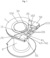
Fig. 1 illustrates a schematic structural diagram of an embodiment of a bobbin structure according to the present invention from a first perspective. -
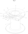
Fig. 2 illustrates a schematic structural diagram of an embodiment of a bobbin structure according to the present invention from a second perspective. -
Fig. 3 illustrates a schematic diagram of mounting a grounding tab on a bobbin structure according to an embodiment of a bobbin structure of the present invention. -
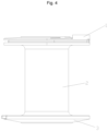
Fig. 4 illustrates a schematic plan of an embodiment of a bobbin structure according to the present invention. -
Fig. 5 illustrates an assembly diagram of mounting a magnetic conductive frame and a bobbin structure according to an embodiment of an electromagnetic coil of the present invention. -
Fig. 6 illustrates a schematic diagram of a plastic-sealed electromagnetic coil according to an embodiment of an electromagnetic coil of the present invention. - Herein, the above drawings include the following reference signs.
1. First bobbin section; 2. Second bobbin section; 3. Third bobbin section; 10. First recess; 100. Grounding tab; 110. Third limiting protrusion; 101. First mounting protrusion; 102. Mounting recess; 20. Guide groove; 103. First limiting protrusion; 104. Annular protrusion; 30. Second recess; 40. Second mounting protrusion; 41. First protrusion section; 42. Second protrusion section; 50. Second limiting protrusion; 200. Magnetic conductive frame. - It is to be noted that the embodiments in the present invention and features in the embodiments can be combined with each other without conflict. The present invention is described in detail below with reference to the drawings and in conjunction with the embodiments.
- It is to be noted that terms used herein are only for the purpose of describing the specific implementations and not intended to limit exemplary implementations of the present invention. For example, singular forms, used herein, are also intended to include plural forms, unless otherwise clearly pointed out. In addition, it is also to be understood that terms "contain" and/or "include" used in the specification refer/refers to existence of features, steps, operations, apparatuses, components and/or combinations thereof.
- As shown in
Fig. 1 to Fig. 4 , the present invention provides a bobbin structure. The bobbin structure includes a first bobbin section 1. The first bobbin section 1 includes first mountingprotrusions 101 and a mountingrecess 102, the first mountingprotrusions 101 being located in the mountingrecess 102, and the first mountingprotrusions 101 being configured to support agrounding tab 100. The first bobbin section 1 further includes afirst recess 10. The mountingrecess 102 is formed in a bottom wall of thefirst recess 10, so that plastic material flows from thefirst recess 10 to the mountingrecess 102 for plastic sealing. - The bobbin structure of the present invention includes the first bobbin section 1. The first bobbin section 1 includes the first mounting
protrusions 101 and the mountingrecess 102, the first mountingprotrusions 101 being located in the mountingrecess 102, and the first mountingprotrusions 101 being configured to support thegrounding tab 100. The first bobbin section 1 further includes thefirst recess 10. The mountingrecess 102 is formed in the bottom wall of thefirst recess 10, so that the plastic material flows from thefirst recess 10 to the mountingrecess 102 for plastic sealing. In the present invention, thefirst recess 10 is added, and the mountingrecess 102 is formed in the bottom wall of thefirst recess 10, so that in an injection molding process, the plastic material flows from thefirst recess 10 to the mountingrecess 102 and fills thefirst recess 10, thereby increasing the injection molding amount, increasing the injection molding thickness, and improving the insulation performance. - It is to be noted that the plastic material in the present invention is a Bulk Molding Compound (BMC).
- In some embodiments, one end of the
first recess 10 extends to the outer periphery of the first bobbin section 1, and the other end of thefirst recess 10 extends toward the middle of the first bobbin section 1. - In some embodiments, a recess gap is formed between the first mounting
protrusion 101 and the mountingrecess 102. - In some embodiments, the first bobbin section 1 further includes a
guide groove 20. Theguide groove 20 is communicated with thefirst recess 10, and theguide groove 20 is arranged on an outer side of thefirst recess 10, so that the plastic material flows from theguide groove 20 to thefirst recess 10. - In some embodiments, a plurality of
guide grooves 20 are provided, and the plurality ofguide grooves 20 are arranged around thefirst recess 10. - In some embodiments, two
guide grooves 20 are provided, and the twoguide grooves 20 are respectively arranged on two opposite ends of thefirst recess 10. - Optionally, the
guide grooves 20 are polygonal. - In some embodiments, the
guide grooves 20 are quadrilateral, and theguide grooves 20 are of a strip-shaped structure. - In some embodiments, the depth of the
guide groove 20 gradually increases in a direction close to thefirst recess 10, so that the plastic material may flow in a direction toward thefirst recess 10. - Optionally, the maximum depth of the
guide groove 20 is less than the minimum depth of thefirst recess 10, so that a step is formed between theguide groove 20 and thefirst recess 10; or the maximum depth of theguide groove 20 is equal to the minimum depth of thefirst recess 10, so that a smooth transition is formed between theguide groove 20 and thefirst recess 10. - In some embodiments, the first bobbin section 1 further includes a plurality of first limiting
protrusions 103. Two opposite sides of the first mountingprotrusion 101 are each provided with at least one first limitingprotrusion 103 to limit thegrounding tab 100 in a width direction of thegrounding tab 100. - As shown in
Fig. 1 to Fig. 3 , both sides of the first mountingprotrusion 101 are each provided with the plurality of first limitingprotrusions 103, and the plurality of first limitingprotrusions 103 located on one side of the first mountingprotrusion 101 are arranged at intervals in an extension direction of thegrounding tab 100. - In some embodiments, a plurality of first mounting
protrusions 101 are provided, and the plurality of first mountingprotrusions 101 are arranged at intervals in the extension direction of thegrounding tab 100. In this way, the mountingrecess 102 is formed between the two adjacent first mountingprotrusions 101, so that the plastic material flows to the mountingrecess 102 at the outer periphery of the first mountingprotrusion 101, and also flows through the mountingrecess 102 between the two adjacent first mountingprotrusions 101, and the plurality of first limitingprotrusions 103 are arranged at intervals in the extension direction of thegrounding tab 100, so that the plastic material flows through the recess gap between the two adjacent first limitingprotrusions 103, so that the amount of a plastic sealing material (BMC) of thegrounding tab 100 is increased. - In some embodiments, the
grounding tab 100 includes a third limitingprotrusion 110. The third limitingprotrusion 110 is located on one side, close to the first mountingprotrusion 101, of thegrounding tab 100, and the third limitingprotrusion 110 is configured to limit a magneticconductive frame 200. - In some embodiments, the first bobbin section 1 includes an
annular protrusion 104. Theannular protrusion 104 protrudes from an outer surface of the first bobbin section 1, and asecond recess 30 is formed in theannular protrusion 104, so that after the magneticconductive frame 200 is placed on the first bobbin section 1, the plastic material fills thesecond recess 30 for plastic sealing. In this way, the magneticconductive frame 200 and thesecond recess 30 are fixedly connected by injection molding to prevent the magnetic conductive frame from falling off; and/or one end of thefirst recess 10 extends to the outer periphery of the first bobbin section 1, and the other end of thefirst recess 10 extends to theannular protrusion 104. - In some embodiments, the
second groove 30 is of a strip-shaped structure. - In some embodiments, the depth of the
second recess 30 is less than that of thefirst recess 10, so that a first step is formed between thesecond recess 30 and thefirst recess 10. - In some embodiments, the bobbin structure further includes second mounting
protrusions 40. The second mountingprotrusions 40 are arranged in thefirst recess 10, or the second mountingprotrusions 40 are configured to enclose thefirst recess 10, so as to support the magneticconductive frame 200 through the second mountingprotrusions 40. - In some embodiments, the second mounting
protrusion 40 is of an L-shaped structure composed of afirst protrusion section 41 and a second protrusion section 42, and a free end of thefirst protrusion section 41 extends toward the first mountingprotrusion 101. - In some embodiments, the
first protrusion section 41 is configured to support the magneticconductive frame 200, and the plastic material fills thefirst recess 10 between the second protrusion section 42 and the first limitingprotrusion 103, so that the magneticconductive frame 200 and thefirst recess 10 here are fixedly connected by injection molding, thereby further preventing the magneticconductive frame 200 from falling off. - In some embodiments, two second mounting
protrusions 40 are provided, and the two second mountingprotrusions 40 are respectively arranged on the sides, away from the first mountingprotrusion 101, of the first limitingprotrusions 103, and the second mountingprotrusions 40 and the first limitingprotrusions 103 are arranged at intervals to allow the plastic material to flow through and fill thefirst recess 10 between the second mountingprotrusions 40 and the first limitingprotrusions 103. - In some embodiments, the first bobbin section further includes two second limiting
protrusions 50. The two second limitingprotrusions 50 are respectively arranged on two opposite ends of thefirst recess 10, so as to limit the magneticconductive frame 200 through the two limitingprotrusions 50. - In some embodiments, a wall surface, close to one side of the
guide groove 20, of the second limitingprotrusion 50 is a limiting surface, so that the magneticconductive frame 200 is limited through the limiting surface. - In some embodiments, the
guide grooves 20 and the second limitingprotrusions 50 are arranged at intervals in the extension direction of the grounding tab. - In some embodiments, the second mounting
protrusion 40 and the second limitingprotrusion 50 are of an integrated structure. - As shown in
Fig. 4 , the bobbin structure further includes asecond bobbin section 2 and a third bobbin section 3. The first bobbin section 1 and the third bobbin section 3 are respectively arranged on both ends of thesecond bobbin section 2. The outer perimeter of the third bobbin section 3 gradually increases in a direction close to the first bobbin section 1. In this way, package with the plastic sealing material is facilitated. - Referring to
Fig. 5 and Fig. 6 , the present invention further provides an electromagnetic coil, including a bobbin structure. The bobbin structure is the above bobbin structure. The direction of the arrow inFig. 5 is a flow direction of a plastic material. - From the above description, it can be seen that the above embodiments of the present invention achieve the following technical effects.
- The bobbin structure of the present invention includes the first bobbin section 1. The first bobbin section 1 includes the first mounting
protrusions 101 and the mountingrecess 102, the first mountingprotrusions 101 being located in the mountingrecess 102, and the first mountingprotrusions 101 being configured to support thegrounding tab 100. The first bobbin section 1 further includes thefirst recess 10. The mountingrecess 102 is formed in the bottom wall of thefirst recess 10, so that the plastic material flows from thefirst recess 10 to the mountingrecess 102 for plastic sealing. In the present invention, thefirst recess 10 is added, and the mountingrecess 102 is formed in the bottom wall of thefirst recess 10, so that in an injection molding process, the plastic material flows from thefirst recess 10 to the mountingrecess 102 and fills thefirst recess 10, thereby increasing the injection molding amount, increasing the injection molding thickness, and improving the insulation performance. - For ease of description, spatially relative terms such as "over", "above", "on an upper surface" and "upper" can be used herein for describing a spatial position relation between a device or feature and other devices or features shown in the drawings. It should be understood that the spatially relative terms are intended to contain different orientations of the device in usage or operation besides the orientations of the devices described in the drawings. For example, if the devices in the drawings are inverted, those described as "above other devices or structures" or "over other devices or structures" will then be positioned as "below other devices or structures" or "under other devices or structures". Thus, the exemplary term "above" can include both "above" and "below" orientations. The device can also be positioned in various other ways (rotated 90 degrees or at other orientations) and the spatially relative descriptions used herein are interpreted accordingly.
- Furthermore, it is to be noted that the use of the words "first", "second" and the like to define parts is only for the convenience of distinguishing the corresponding parts, unless otherwise stated, the words have no special meaning, and therefore cannot be construed as limiting the scope of protection of the present invention.
- The above is only the preferred embodiments of the present invention, and is not intended to limit the present invention, and for those of ordinary skill in the art, various modifications and changes can be made to the present invention. Any modifications, equivalent substitutions, improvements, etc. within the spirit and scope of the present invention shall be included in the scope of protection of the present invention.
Claims (15)
- A bobbin structure, wherein the bobbin structure comprises:a first bobbin section (1), comprises a first mounting protrusions (101) and a mounting recess (102), the first mounting protrusions (101) being disposed on the mounting recess (102), and the first mounting protrusions (101) being configured to support a grounding tab (100);the first bobbin section (1) further comprises a first recess (10), the mounting recess (102) is disposed on a bottom wall of the first recess (10), so that plastic material flows from the first recess (10) to the mounting recess (102) for plastic sealing.
- The bobbin structure as claimed in claim 1, wherein,an end of the first recess (10) extends to an outer periphery of the first bobbin section (1), andthe other end of the first recess (10) extends toward the middle of the first bobbin section (1).
- The bobbin structure as claimed in claim 1, wherein the first bobbin section (1) further comprises a guide groove (20), the guide groove (20) is communicated with the first recess (10), and the guide groove (20) is disposed on an outer side of the first recess (10), so that the plastic material flows from the guide groove (20) to the first recess (10).
- The bobbin structure as claimed in claim 3, wherein a plurality of guide grooves (20) are provided, and the plurality of guide grooves (20) are disposed around the first recess (10).
- The bobbin structure as claimed in claim 3, wherein two guide grooves (20) are provided, and the two guide grooves (20) are respectively disposed on two opposite ends of the first recess (10).
- The bobbin structure as claimed in claim 3, wherein the depth of the guide groove (20) gradually increases in a direction close to the first recess (10), and the maximum depth of the guide groove (20) is less than or equal to the minimum depth of the first recess (10).
- The bobbin structure as claimed in claim 1, wherein the first bobbin section (1) further comprises a plurality of first limiting protrusions (103), two opposite sides of the first mounting protrusion (101) are each provided with at least one first limiting protrusion (103) to limit the grounding tab (100) in a width direction of the grounding tab (100).
- The bobbin structure as claimed in claim 7, wherein a plurality of first limiting protrusions (103) are disposed on both sides of the first mounting protrusion (101), and the plurality of first limiting protrusions (103) disposed on one side of the first mounting protrusion (101) are disposed at intervals in an extension direction of the grounding tab (100).
- The bobbin structure as claimed in claim 1, wherein a plurality of first mounting protrusions (101) are provided, and the plurality of first mounting protrusions (101) are disposed at intervals in an extension direction of the grounding tab (100).
- The bobbin structure as claimed in claim 1, wherein the first bobbin section (1) comprises an annular protrusion (104), the annular protrusion (104) protrudes from an outer surface of the first bobbin section (1), and a second recess (30) is disposed on the annular protrusion (104), so that after a magnetic conductive frame (200) is placed on the first bobbin section (1), the plastic material fills the second recess (30) for plastic sealing; and/or one end of the first recess (10) extends to the outer periphery of the first bobbin section (1) and the other end of the first recess (10) extends to the annular protrusion (104).
- The bobbin structure as claimed in claim 10, wherein,
the depth of the second recess (30) is less than the depth of the first recess (10), so that a first step is disposed between the second recess (30) and the first recess (10). - The bobbin structure as claimed in claim 1, the bobbin structure further comprises:
a second mounting protrusion (40), disposed on the first recess (10), or the second mounting protrusion (40) is configured to enclose the first recess (10), so that a magnetic conductive frame (200) is supported by the second mounting protrusion (40). - The bobbin structure as claimed in claim 12, wherein the second mounting protrusion (40) is an L-shaped structure formed by a first protrusion section (41) and a second protrusion section (42), and a free end of the first protrusion section (41) extends toward the first mounting protrusion (101).
- The bobbin structure as claimed in claim 1, wherein the first bobbin section (1) further comprises:
two second limiting protrusions (50), respectively disposed on two opposite ends of the first recess (10), so that a magnetic conductive frame (200) is limited by the two limiting protrusions (50). - An electromagnetic coil, comprising a bobbin structure, wherein the bobbin structure is the bobbin structure as claimed in any one of claims 1 to 14.
Applications Claiming Priority (2)
| Application Number | Priority Date | Filing Date | Title |
|---|---|---|---|
| CN202210362024.6A CN116936241A (en) | 2022-04-07 | 2022-04-07 | Skeleton texture and solenoid |
| PCT/CN2023/084494 WO2023193638A1 (en) | 2022-04-07 | 2023-03-28 | Bobbin structure and electromagnetic coil |
Publications (2)
| Publication Number | Publication Date |
|---|---|
| EP4492414A1 true EP4492414A1 (en) | 2025-01-15 |
| EP4492414A4 EP4492414A4 (en) | 2025-07-02 |
Family
ID=88244018
Family Applications (1)
| Application Number | Title | Priority Date | Filing Date |
|---|---|---|---|
| EP23784202.6A Pending EP4492414A4 (en) | 2022-04-07 | 2023-03-28 | COIL STRUCTURE AND ELECTROMAGNETIC COIL |
Country Status (3)
| Country | Link |
|---|---|
| EP (1) | EP4492414A4 (en) |
| CN (1) | CN116936241A (en) |
| WO (1) | WO2023193638A1 (en) |
Family Cites Families (16)
| Publication number | Priority date | Publication date | Assignee | Title |
|---|---|---|---|---|
| JPH1167558A (en) * | 1997-08-22 | 1999-03-09 | Tec Corp | Electromagnetic device |
| JPH11283847A (en) * | 1998-03-31 | 1999-10-15 | Taiyo Yuden Co Ltd | Surface-mounted coil |
| KR200232054Y1 (en) * | 1998-07-03 | 2001-08-07 | 황의선 | Bobbin structure of feed valve |
| CN201149123Y (en) * | 2007-11-29 | 2008-11-12 | 杭州神林电子有限公司 | Electromagnetic coil of electromagnetic water intake valve for household electrical appliance |
| US8102237B2 (en) * | 2008-06-12 | 2012-01-24 | Power Integrations, Inc. | Low profile coil-wound bobbin |
| KR101197274B1 (en) * | 2008-06-16 | 2012-11-05 | 우리산업 주식회사 | Field coil ass'y of electromagnetic clutch |
| CN202957120U (en) * | 2012-11-26 | 2013-05-29 | 浙江盾安机械有限公司 | Novel electromagnetic coil framework inserting piece structure |
| CN202927212U (en) * | 2012-11-30 | 2013-05-08 | 浙江三花股份有限公司 | Coil part of electromagnetic valve |
| CN203444946U (en) * | 2013-09-06 | 2014-02-19 | 台湾东电化股份有限公司 | Transformer bobbin structure |
| DE102014214074A1 (en) * | 2014-07-18 | 2016-01-21 | Robert Bosch Gmbh | Winding diagram for a transformer of a boost converter and ignition system for supplying a spark gap of an internal combustion engine with electrical energy |
| US10263372B2 (en) * | 2016-04-18 | 2019-04-16 | Foxconn Interconnect Technology Limited | Electrical connector having insulative housing with a rear stepped portion assisting in formation of a waterproof sheet |
| CN205911104U (en) * | 2016-08-06 | 2017-01-25 | 中山市港利制冷配件有限公司 | Solenoid skeleton |
| CN108528354B (en) * | 2018-06-04 | 2023-08-08 | 威马智慧出行科技(上海)有限公司 | Vehicle-mounted camera bracket and automobile comprising same |
| US11978585B2 (en) * | 2019-03-13 | 2024-05-07 | Tds Co. Ltd | Coil device and method for manufacturing same and bobbin for coil used therein |
| CN209937561U (en) * | 2019-05-15 | 2020-01-14 | 友信精密实业(深圳)有限公司 | Injection mold for submarine gel |
| CN217306281U (en) * | 2022-04-07 | 2022-08-26 | 浙江盾安禾田金属有限公司 | Skeleton texture and solenoid |
-
2022
- 2022-04-07 CN CN202210362024.6A patent/CN116936241A/en active Pending
-
2023
- 2023-03-28 EP EP23784202.6A patent/EP4492414A4/en active Pending
- 2023-03-28 WO PCT/CN2023/084494 patent/WO2023193638A1/en not_active Ceased
Also Published As
| Publication number | Publication date |
|---|---|
| EP4492414A4 (en) | 2025-07-02 |
| WO2023193638A1 (en) | 2023-10-12 |
| CN116936241A (en) | 2023-10-24 |
Similar Documents
| Publication | Publication Date | Title |
|---|---|---|
| US10153081B2 (en) | Coil component | |
| KR101627128B1 (en) | Coil component | |
| US9508482B2 (en) | Reactor | |
| US8779883B2 (en) | Coil device | |
| US8791786B2 (en) | Coil device | |
| US8736412B2 (en) | Magnetic element | |
| US9960531B2 (en) | Cable connector | |
| US8878640B2 (en) | Common-mode choke coil | |
| US20130307657A1 (en) | Surface mount inductor | |
| KR102601486B1 (en) | Bobbin and transformer with the same | |
| EP4492414A1 (en) | Bobbin structure and electromagnetic coil | |
| KR102647781B1 (en) | Bobbin and transformer with the same | |
| US7696851B1 (en) | Transformer with separated bobbin | |
| US20230290562A1 (en) | Coil device | |
| US8665051B2 (en) | Vertical transformer | |
| CN217306281U (en) | Skeleton texture and solenoid | |
| CN113517105A (en) | Electronic coil and electronic expansion valve with same | |
| US9203224B2 (en) | Electrical junction box | |
| CN109649801B (en) | Display panel packing case | |
| US20200118726A1 (en) | Reactor and manufacturing method thereof | |
| US20190109061A1 (en) | Edge Bend for Isolation Packages | |
| US20190378641A1 (en) | Inductor and inductor manufacturing method | |
| CN213905093U (en) | Inductor core assembly and inductor including the same | |
| US20180122763A1 (en) | Leadless package with non-collapsible bump | |
| JP3654888B2 (en) | Low profile switching transformer |
Legal Events
| Date | Code | Title | Description |
|---|---|---|---|
| STAA | Information on the status of an ep patent application or granted ep patent |
Free format text: STATUS: THE INTERNATIONAL PUBLICATION HAS BEEN MADE |
|
| PUAI | Public reference made under article 153(3) epc to a published international application that has entered the european phase |
Free format text: ORIGINAL CODE: 0009012 |
|
| STAA | Information on the status of an ep patent application or granted ep patent |
Free format text: STATUS: REQUEST FOR EXAMINATION WAS MADE |
|
| 17P | Request for examination filed |
Effective date: 20241010 |
|
| AK | Designated contracting states |
Kind code of ref document: A1 Designated state(s): AL AT BE BG CH CY CZ DE DK EE ES FI FR GB GR HR HU IE IS IT LI LT LU LV MC ME MK MT NL NO PL PT RO RS SE SI SK SM TR |
|
| A4 | Supplementary search report drawn up and despatched |
Effective date: 20250603 |
|
| RIC1 | Information provided on ipc code assigned before grant |
Ipc: F16K 31/06 20060101ALI20250527BHEP Ipc: H01F 5/02 20060101ALI20250527BHEP Ipc: H01F 5/00 20060101ALI20250527BHEP Ipc: H01F 27/30 20060101AFI20250527BHEP |
|
| DAV | Request for validation of the european patent (deleted) | ||
| DAX | Request for extension of the european patent (deleted) |