EP4492412A1 - Transformer - Google Patents
Transformer Download PDFInfo
- Publication number
- EP4492412A1 EP4492412A1 EP23185228.6A EP23185228A EP4492412A1 EP 4492412 A1 EP4492412 A1 EP 4492412A1 EP 23185228 A EP23185228 A EP 23185228A EP 4492412 A1 EP4492412 A1 EP 4492412A1
- Authority
- EP
- European Patent Office
- Prior art keywords
- transformer
- wall
- winding
- core
- curved portion
- Prior art date
- Legal status (The legal status is an assumption and is not a legal conclusion. Google has not performed a legal analysis and makes no representation as to the accuracy of the status listed.)
- Pending
Links
Images




Classifications
-
- H—ELECTRICITY
- H01—ELECTRIC ELEMENTS
- H01F—MAGNETS; INDUCTANCES; TRANSFORMERS; SELECTION OF MATERIALS FOR THEIR MAGNETIC PROPERTIES
- H01F27/00—Details of transformers or inductances, in general
- H01F27/02—Casings
-
- H—ELECTRICITY
- H01—ELECTRIC ELEMENTS
- H01F—MAGNETS; INDUCTANCES; TRANSFORMERS; SELECTION OF MATERIALS FOR THEIR MAGNETIC PROPERTIES
- H01F27/00—Details of transformers or inductances, in general
- H01F27/33—Arrangements for noise damping
-
- H—ELECTRICITY
- H01—ELECTRIC ELEMENTS
- H01F—MAGNETS; INDUCTANCES; TRANSFORMERS; SELECTION OF MATERIALS FOR THEIR MAGNETIC PROPERTIES
- H01F30/00—Fixed transformers not covered by group H01F19/00
- H01F30/06—Fixed transformers not covered by group H01F19/00 characterised by the structure
-
- H—ELECTRICITY
- H01—ELECTRIC ELEMENTS
- H01F—MAGNETS; INDUCTANCES; TRANSFORMERS; SELECTION OF MATERIALS FOR THEIR MAGNETIC PROPERTIES
- H01F27/00—Details of transformers or inductances, in general
- H01F27/34—Special means for preventing or reducing unwanted electric or magnetic effects, e.g. no-load losses, reactive currents, harmonics, oscillations, leakage fields
- H01F2027/348—Preventing eddy currents
Definitions
- the present disclosure is related to a transformer.
- Transformers are used to transfer an output voltage of an electrical circuit to an input voltage for another electrical circuit.
- Transformers comprise an active part including windings which are closed in a tank or housing. In general, it is a challenge to increase the efficiency of a transformer.
- Embodiments of the present disclosure relate to a transformer that enable reliable operation and an improvement in efficiency and that contribute to keep operation noise low.
- a transformer comprises at least a core and at least one winding for transforming current or voltage electromagnetically, wherein the at least one winding surrounds the core with respect to a lateral direction of the transformer and the core and the winding are configured to cause a predetermined magnetic flux during operation of the transformer.
- the transformer further comprises a housing that encloses the core and the winding with respect to the lateral direction of the transformer such that the winding is arranged between the core and the housing.
- the housing comprises an outer wall with at least one curved portion that is formed in coordination with magnetic field lines of the magnetic flux of the transformer that arises during operation.
- a transformer Due to the described configuration with one or more curved portions at a respective outer wall a transformer is feasible that enables reliable operation and an improvement in efficiency and that further contributes to keep operation noise low.
- the described transformer configuration With one or more curved portions adapted in coordination with the specific magnetic field characteristics of the transformer it is feasible to reduce the eddy currents in a wall of the housing, e.g. by 1% or more or even 5% or more compared to a conventional design without curved surfaces on outer wall. It is further possible to keep the performance losses and a load noise generation low. Moreover, the described configuration enables to keep the noise generation low so as to reduce a source of vibrations and sound propagation resulting in an annoying hum. There is no need for additional elements placed at a tank wall to reduce losses and/or noise generation. However, additional elements can be applied to even improve loss reduction.
- the one or more curved portions are formed by deliberate shaping of the outer wall using predetermined curvatures overall or at one or more strategic locations where a higher density of the magnetic field lines is to be expected to penetrate the housing or the outer wall.
- the described configuration of the transformer contributes to minimize or alter the eddy current effect on the housing walls.
- the curved portion comprises a predetermined radius of curvature, e.g. formed in coordination with a height of the outer wall.
- the radius of curvature is given as 1% to 50% of the height of the outer wall.
- the height of the transformer or the outer wall of the transformer housing can have a value between 0.2 m and 20 m, for example.
- the radius of curvature can be given with 1 cm or greater or 10 cm or greater, or 20 cm or greater.
- the curved portion comprises a predetermined radius of curvature of 10000 cm or smaller, or of 5000 cm or smaller or of 200 cm or smaller.
- the curved portion can comprise more than one given radius of curvature and/or there can be two or more separate curved portions formed at a respective outer wall of the housing comprising different or the same radii of curvature.
- the outer wall comprises two or more curved portions spaced apart from each other, wherein one curved portion is formed in an upper region of the outer wall and another curved portion is formed in a lower region of the outer wall with respect to a longitudinal axis of the transformer across the lateral direction.
- the outer wall can be formed flat between the two curved portions or can comprise one or more further curved portions.
- the outer wall comprises an overall convex shape with respect to a longitudinal direction of the transformer across the lateral direction such that a distance between the winding and a middle portion of the outer wall is bigger than a distance between the winding and an upper region and a distance between the winding and a bottom region of the outer wall.
- the curved portions can form the entire outer wall at a respective side of the housing.
- the at least one curved portion is formed circumferentially surrounding at the outer walls of the housing.
- the housing can be formed cube-shaped or cuboid-shaped and hence comprising a top wall, a bottom wall and four outer walls.
- the housing can be formed cylindrical with a circular or ellipsoidal outer wall with respect to a cross section along the lateral directions.
- the at least one curved portion is formed with a hemi-spherical or semi-ellipsoidal shape.
- the transformer comprises two or more windings surrounding the core or an associated further core. At least one winding is configured to operate at a voltage of 1 kV or above. For example, one winding is configured to operate at a relative low voltage within a range of 100 V and 1000 kV, and a further winding is configured to operate at a relative high voltage within a range of 1 kV and 2000 kV.
- the material of the core(s) can be a ferromagnetic material, e.g. silicon steel, ferrite and/or amorphous magnetic material.
- the material of the winding(s) can be aluminum and/or copper conductor wrapped in an insulating material, e.g. paper.
- the housing or the outer wall of the transformer can comprise a material with a conductivity of 100000 S/m or greater and a thickness of 1 mm up to 25 mm, for example.
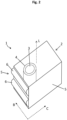
- Figure 1 illustrates an embodiment of a transformer 1 in a perspective view.
- the transformer 1 comprises a core 3 and at least one winding 4 for transforming current electromagnetically.
- the at least one winding 4 encloses or surrounds the core 3 with respect to a lateral directions B, C of the transformer 1 and the core 3 and the winding 4 are configured to cause a predetermined magnetic flux during operation of the transformer 1.
- the transformer 1 further comprises a housing 2 that encloses the core 3 and the winding 4 with respect to the lateral directions B, C such that the winding 4 is arranged between the core 3 and the housing 2.
- the housing 2 comprises an outer wall 5 with a curved portion 6 that is formed in coordination with magnetic field lines 7 of the magnetic flux of the transformer 1 that arises during operation (see Figs. 7-9 ) .
- the transformer 1 at least comprises one curved portion 6 at one associated outer wall 5.
- the transformer 1 can comprise two or more curved portions 6 at a corresponding outer wall 5 (see Figs. 2-7 ).
- the housing 2 of the transformer 1 is typically cuboid or cube-shaped substantially. Accordingly, the housing 2 comprises a top wall, a bottom wall and four outer walls 5.
- Each outer wall 5 can comprise one or more curved portions 6.
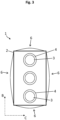
- the four outer walls 5 can comprise respective two curved portions 6 each shaped as a half cylinder as illustrated in the Figs. 1 and 2 .
- the curved portions 6 can circumferentially surround the housing 2 and the inner components at an upper region 8 and a lower region 9 of the associated outer wall 5.
- the top and/or the bottom wall can comprise one or more curved portions.
- the transformer 1 at least comprises one core 3 and one surrounding winding 4.
- the transformer 1 can comprise two or more cores 3 and/or windings 4, 10 (see Figs. 1-5 ).
- a respective core 3 can be surrounded by two or more windings 4, 10 (see Figs. 6-9 ).
- the winding 4 can realize an inner winding configured to transform low voltage within a range of 100 V and 1000 kV, for example.
- the transformer 1 can comprise a further winding 10 that encloses or surrounds the core 3 and the inner winding 4 and hence realizing an outer winding configured to transform high voltage within a range of 1 kV and 2000 kV, for example.
- the one or more curved portions 6 are preferably formed also in coordination with the associated one or more cores 3 and/or windings 4, 10.
- the curved portions 6 are formed at predetermined locations at a respective outer wall 5 where a relative large interaction between the penetrating magnetic field lines 7 and the housing 2 is to be expected depending on the characteristics of the transformer 1 or the inner components such as the core(s) 3 and/or winding(s) 4, 10.
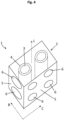
- the housing 2 can comprise respective elongated curved portions 6 (see Figs. 1-3 ) and/or respective single curved portions 6 (see Figs. 4 and 5 ).
- the curved portions 6 can all comprise the same or different shapes depending on the application and the characteristics of the transformer 1 and its inner components.
- a respective curved portion 6 can comprise a shape of a hemi-cylinder, a hemi-sphere or a semi-ellipsoid, for example.
- further shapes of the one or more curved portions 6, e.g. rectangular or cuboid shapes can also contribute to a beneficial performance of the transformer 1.
- the respective curved portion 6 can contribute to an reduced angle A of incidence of the magnetic field lines 7 that penetrates the outer wall 5 of the housing 2 compared to a flat outer surface wall (see Figs. 7 and 8 ).
- a stray magnetic flux interacts with a tank wall or outer wall 5 of the housing creating unwanted eddy currents.
- This eddy current causes losses and strongly influences the noise/vibration under loaded condition.
- the outer walls 5 with one or more curved portions 6 can alter the distribution of eddy currents and can beneficially reduce performance losses and noise generation of the transformer 1. Stray flux is inevitably produced in transformers during operation, but the specific configuration of the housing 2 and its walls can manipulate how it interacts with the outer walls 5.
- the curved portions 6 can be formed at separated strategic locations (see Figs. 6 and 7 ) or can be formed to realize an overall curved outer wall 5 (see Figs.8 and 9 ).
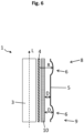
- a respective curved portion 6 has one or more given radii R of curvature realizing a wanted curved shape to change the stray flux interacting with the tank wall (see Fig. 6 ). Accordingly, in the case of at least two separated curved portions 6 at one outer wall 5 a distance D between the inner components, i.e. the core 3 and the winding(s) 4, 10, and the outer wall 5 in the region of the respective curved portion 6 is bigger than in a middle region between the curved portions 6 as illustrated in Fig. 6 . Thus, the curved portions 6 realize an increased distance D that can cause a reduced interaction of stray magnetic flux with the tank wall.
- a respective outer wall 5 can also comprise only one curved portion 6 which can form basically the whole outer wall 5 as indicated in the Fig. 8 and 9 .
- the Figs. 8 and 9 illustrate a schematic cross section view of one side of the core 3 or the transformer 1 according to a cross-section along a transverse or lateral direction B or C and a longitudinal direction L of the transformer 1 perpendicular to the lateral directions B and C.
- Fig. 8 there are relative small flat portions of the outer wall 5 at the upper region 8 and at the lower region 9 and a predominantly large curved portion 6.
- a distance D between the inner components of the transformer 1 and the outer wall 5 in the middle region is bigger than in the upper region 8 and the lower region 9 (see also Fig. 9).
- Fig. 9 illustrates an overall curved portion 6 which form the entire outer wall 5. Such configurations can reduce the eddy current effect locally and hence can contribute to reduced performance losses and noise generation of the transformer 1 during operation.
Landscapes
- Engineering & Computer Science (AREA)
- Power Engineering (AREA)
- Coils Or Transformers For Communication (AREA)
Abstract
A transformer (1) comprises a core (3) and at least one winding (4, 10) for transforming current electromagnetically, wherein the at least one winding (4, 10) encloses the core (3) with respect to a lateral direction (B, C) of the transformer (1) and the core (3) and the winding (4, 10) are configured to cause a predetermined magnetic flux during operation of the transformer (1). The transformer (1) further comprises a housing (2) enclosing the core (3) and the winding (4, 10) with respect to the lateral direction (B, C) of the transformer (1) such that the winding (4, 10) is arranged between the core (3) and the housing (2). The housing (2) comprises an outer wall (5) with at least one curved portion (6) that is formed in coordination with magnetic field lines (7) of the magnetic flux of the transformer (1) that arises during operation.
Description
- The present disclosure is related to a transformer.
- Transformers are used to transfer an output voltage of an electrical circuit to an input voltage for another electrical circuit. Transformers comprise an active part including windings which are closed in a tank or housing. In general, it is a challenge to increase the efficiency of a transformer.
- Embodiments of the present disclosure relate to a transformer that enable reliable operation and an improvement in efficiency and that contribute to keep operation noise low.
- According to an embodiment, a transformer comprises at least a core and at least one winding for transforming current or voltage electromagnetically, wherein the at least one winding surrounds the core with respect to a lateral direction of the transformer and the core and the winding are configured to cause a predetermined magnetic flux during operation of the transformer. The transformer further comprises a housing that encloses the core and the winding with respect to the lateral direction of the transformer such that the winding is arranged between the core and the housing. The housing comprises an outer wall with at least one curved portion that is formed in coordination with magnetic field lines of the magnetic flux of the transformer that arises during operation.
- Due to the described configuration with one or more curved portions at a respective outer wall a transformer is feasible that enables reliable operation and an improvement in efficiency and that further contributes to keep operation noise low.
- It is a finding of the present disclosure that conventional designs of a transformer comprise active parts closed in a tank with rectangular shape with substantially flat walls. Arising stray magnetic flux of the transformer induces eddy currents in the tank wall which leads to losses in performance of the transformer. In addition, the stray magnetic flux and the induced eddy currents interaction leads to load noise.
- By use of the described transformer configuration with one or more curved portions adapted in coordination with the specific magnetic field characteristics of the transformer it is feasible to reduce the eddy currents in a wall of the housing, e.g. by 1% or more or even 5% or more compared to a conventional design without curved surfaces on outer wall. It is further possible to keep the performance losses and a load noise generation low. Moreover, the described configuration enables to keep the noise generation low so as to reduce a source of vibrations and sound propagation resulting in an annoying hum. There is no need for additional elements placed at a tank wall to reduce losses and/or noise generation. However, additional elements can be applied to even improve loss reduction. The one or more curved portions are formed by deliberate shaping of the outer wall using predetermined curvatures overall or at one or more strategic locations where a higher density of the magnetic field lines is to be expected to penetrate the housing or the outer wall. Thus, the described configuration of the transformer contributes to minimize or alter the eddy current effect on the housing walls.
- According to an embodiment of the transformer, the curved portion comprises a predetermined radius of curvature, e.g. formed in coordination with a height of the outer wall. For example, the radius of curvature is given as 1% to 50% of the height of the outer wall. The height of the transformer or the outer wall of the transformer housing can have a value between 0.2 m and 20 m, for example. Alternatively or additionally, the radius of curvature can be given with 1 cm or greater or 10 cm or greater, or 20 cm or greater. Alternatively or additionally, the curved portion comprises a predetermined radius of curvature of 10000 cm or smaller, or of 5000 cm or smaller or of 200 cm or smaller. Moreover, the curved portion can comprise more than one given radius of curvature and/or there can be two or more separate curved portions formed at a respective outer wall of the housing comprising different or the same radii of curvature.
- According to a further embodiment of the transformer, the outer wall comprises two or more curved portions spaced apart from each other, wherein one curved portion is formed in an upper region of the outer wall and another curved portion is formed in a lower region of the outer wall with respect to a longitudinal axis of the transformer across the lateral direction. The outer wall can be formed flat between the two curved portions or can comprise one or more further curved portions.
- According to a further embodiment of the transformer, the outer wall comprises an overall convex shape with respect to a longitudinal direction of the transformer across the lateral direction such that a distance between the winding and a middle portion of the outer wall is bigger than a distance between the winding and an upper region and a distance between the winding and a bottom region of the outer wall. Thus, the curved portions can form the entire outer wall at a respective side of the housing.
- According to a further embodiment of the transformer, the at least one curved portion is formed circumferentially surrounding at the outer walls of the housing. The housing can be formed cube-shaped or cuboid-shaped and hence comprising a top wall, a bottom wall and four outer walls. Alternatively, the housing can be formed cylindrical with a circular or ellipsoidal outer wall with respect to a cross section along the lateral directions.
- According to a further embodiment of the transformer, the at least one curved portion is formed with a hemi-spherical or semi-ellipsoidal shape.
- According to a further embodiment, the transformer comprises two or more windings surrounding the core or an associated further core. At least one winding is configured to operate at a voltage of 1 kV or above. For example, one winding is configured to operate at a relative low voltage within a range of 100 V and 1000 kV, and a further winding is configured to operate at a relative high voltage within a range of 1 kV and 2000 kV. The material of the core(s) can be a ferromagnetic material, e.g. silicon steel, ferrite and/or amorphous magnetic material. The material of the winding(s) can be aluminum and/or copper conductor wrapped in an insulating material, e.g. paper. The housing or the outer wall of the transformer can comprise a material with a conductivity of 100000 S/m or greater and a thickness of 1 mm up to 25 mm, for example.
- Exemplary embodiments are explained in the following with the aid of schematic drawings and reference numbers. The figures show:
- Figures 1-9
- embodiments of a transformer in different views.
- The accompanying figures are included to provide a further understanding. It is to be understood that the embodiments shown in the figures are illustrative representations and are not necessarily drawn to scale. Identical reference numbers designate elements or components with identical functions. In so far as elements or components correspond to one another in terms of their function in different figures, the description thereof is not repeated for each of the following figures. For the sake of clarity elements might not appear with corresponding reference symbols in all figures possibly.
-
Figure 1 illustrates an embodiment of atransformer 1 in a perspective view. Thetransformer 1 comprises acore 3 and at least one winding 4 for transforming current electromagnetically. The at least one winding 4 encloses or surrounds thecore 3 with respect to a lateral directions B, C of thetransformer 1 and thecore 3 and thewinding 4 are configured to cause a predetermined magnetic flux during operation of thetransformer 1. - The
transformer 1 further comprises ahousing 2 that encloses thecore 3 and the winding 4 with respect to the lateral directions B, C such that thewinding 4 is arranged between thecore 3 and thehousing 2. Thehousing 2 comprises anouter wall 5 with acurved portion 6 that is formed in coordination with magnetic field lines 7 of the magnetic flux of thetransformer 1 that arises during operation (seeFigs. 7-9 ) . - Due to the described configuration of the
transformer 1 with thecurved portion 6 at theouter wall 5 it is contributed to a reliable and efficient operation and to keep operation noise low. - It is pointed out, that the
transformer 1 at least comprises onecurved portion 6 at one associatedouter wall 5. However, according to further embodiments thetransformer 1 can comprise two or morecurved portions 6 at a corresponding outer wall 5 (seeFigs. 2-7 ). Moreover, thehousing 2 of thetransformer 1 is typically cuboid or cube-shaped substantially. Accordingly, thehousing 2 comprises a top wall, a bottom wall and fourouter walls 5. Eachouter wall 5 can comprise one or morecurved portions 6. For example, the fourouter walls 5 can comprise respective twocurved portions 6 each shaped as a half cylinder as illustrated in theFigs. 1 and2 . Thus, thecurved portions 6 can circumferentially surround thehousing 2 and the inner components at anupper region 8 and alower region 9 of the associatedouter wall 5. Additionally, the top and/or the bottom wall can comprise one or more curved portions. - Further, the
transformer 1 at least comprises onecore 3 and one surrounding winding 4. However, alternatively thetransformer 1 can comprise two ormore cores 3 and/orwindings 4, 10 (seeFigs. 1-5 ). Further, arespective core 3 can be surrounded by two ormore windings 4, 10 (seeFigs. 6-9 ). The winding 4 can realize an inner winding configured to transform low voltage within a range of 100 V and 1000 kV, for example. Thetransformer 1 can comprise a further winding 10 that encloses or surrounds thecore 3 and the inner winding 4 and hence realizing an outer winding configured to transform high voltage within a range of 1 kV and 2000 kV, for example. - The one or more
curved portions 6 are preferably formed also in coordination with the associated one ormore cores 3 and/orwindings curved portions 6 are formed at predetermined locations at a respectiveouter wall 5 where a relative large interaction between the penetrating magnetic field lines 7 and thehousing 2 is to be expected depending on the characteristics of thetransformer 1 or the inner components such as the core(s) 3 and/or winding(s) 4, 10. - The
housing 2 can comprise respective elongated curved portions 6 (seeFigs. 1-3 ) and/or respective single curved portions 6 (seeFigs. 4 and5 ). Thecurved portions 6 can all comprise the same or different shapes depending on the application and the characteristics of thetransformer 1 and its inner components. A respectivecurved portion 6 can comprise a shape of a hemi-cylinder, a hemi-sphere or a semi-ellipsoid, for example. However, further shapes of the one or morecurved portions 6, e.g. rectangular or cuboid shapes, can also contribute to a beneficial performance of thetransformer 1. - The respective
curved portion 6 can contribute to an reduced angle A of incidence of the magnetic field lines 7 that penetrates theouter wall 5 of thehousing 2 compared to a flat outer surface wall (seeFigs. 7 and8 ). - It is a finding of the present disclosure that a stray magnetic flux interacts with a tank wall or
outer wall 5 of the housing creating unwanted eddy currents. This eddy current causes losses and strongly influences the noise/vibration under loaded condition. Theouter walls 5 with one or morecurved portions 6 can alter the distribution of eddy currents and can beneficially reduce performance losses and noise generation of thetransformer 1. Stray flux is inevitably produced in transformers during operation, but the specific configuration of thehousing 2 and its walls can manipulate how it interacts with theouter walls 5. Thecurved portions 6 can be formed at separated strategic locations (seeFigs. 6 and7 ) or can be formed to realize an overall curved outer wall 5 (seeFigs.8 and9 ). - A respective
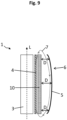
curved portion 6 has one or more given radii R of curvature realizing a wanted curved shape to change the stray flux interacting with the tank wall (seeFig. 6 ). Accordingly, in the case of at least two separatedcurved portions 6 at one outer wall 5 a distance D between the inner components, i.e. thecore 3 and the winding(s) 4, 10, and theouter wall 5 in the region of the respectivecurved portion 6 is bigger than in a middle region between thecurved portions 6 as illustrated inFig. 6 . Thus, thecurved portions 6 realize an increased distance D that can cause a reduced interaction of stray magnetic flux with the tank wall. - A respective
outer wall 5 can also comprise only onecurved portion 6 which can form basically the wholeouter wall 5 as indicated in theFig. 8 and9 . As also shown in theFigs. 6 and7 , theFigs. 8 and9 illustrate a schematic cross section view of one side of thecore 3 or thetransformer 1 according to a cross-section along a transverse or lateral direction B or C and a longitudinal direction L of thetransformer 1 perpendicular to the lateral directions B and C. - According to
Fig. 8 , there are relative small flat portions of theouter wall 5 at theupper region 8 and at thelower region 9 and a predominantly largecurved portion 6. A distance D between the inner components of thetransformer 1 and theouter wall 5 in the middle region is bigger than in theupper region 8 and the lower region 9 (see alsoFig. 9). Fig. 9 illustrates an overallcurved portion 6 which form the entireouter wall 5. Such configurations can reduce the eddy current effect locally and hence can contribute to reduced performance losses and noise generation of thetransformer 1 during operation. - The embodiment shown in the
figures 1 to 9 as stated represent an exemplary embodiment of theimproved transformer 1. Therefore, it does not constitute all embodiments. Actual arrangements may vary from the embodiment shown in the figures. -
- 1
- transformer
- 2
- housing of the transformer
- 3
- core
- 4
- winding
- 5
- outer wall of the housing
- 6
- curved portion of the outer wall
- 7
- magnetic field lines
- 8
- upper region of the outer wall
- 9
- lower region of the outer wall
- 10
- winding
- A
- angle of incidence
- B
- lateral direction of the transformer
- C
- lateral direction of the transformer
- D
- distance between a winding and the outer wall
- L
- longitudinal direction of the transformer
- R
- radius of curvature of a curved portion
Claims (10)
- A transformer (1), comprising:- a core (3) and at least one winding (4, 10) for transforming current electromagnetically, wherein the at least one winding (4, 10) encloses the core (3) with respect to a lateral direction (B, C) of the transformer (1) and the core (3) and the winding (4, 10) are configured to cause a predetermined magnetic flux during operation of the transformer (1), and- a housing (2) enclosing the core (3) and the winding (4, 10) with respect to the lateral direction (B, C) of the transformer (1) such that the winding (4, 10) is arranged between the core (3) and the housing (2), wherein the housing (2) comprises an outer wall (5) with at least one curved portion (6) that is formed in coordination with magnetic field lines (7) of the magnetic flux of the transformer (1) that arises during operation.
- The transformer (1) according to claim 1, wherein the curved portion (6) comprises a predetermined radius of curvature (R) of 1 cm or greater.
- The transformer (1) according to claim 1 or 2, wherein the curved portion (6) comprises a predetermined radius of curvature (R) of 10000 cm or smaller.
- The transformer (1) according to any of the preceding claims, wherein the curved portion (6) comprises a radius of curvature (R) that is given at 1% up to 50% of a height of the outer wall (5).
- The transformer (1) according to any of the preceding claims, wherein the outer wall (5) comprises two or more curved portions (6) spaced apart from each other, wherein one curved portion (6) is formed in an upper region (8) of the outer wall (5) and another curved portion (6) is formed in a lower region (9) of the outer wall (5) with respect to a longitudinal axis (L) of the transformer (1) across the lateral direction (B, C).
- The transformer (1) according to claim 4, wherein the outer wall (5) is formed flat between the two curved portions (6) .
- The transformer (1) according to any of the claims 1 to 3, wherein the outer wall (5) comprises an overall convex shape with respect to a longitudinal direction (L) of the transformer (1) across the lateral direction (B, C) such that a distance (D) between the winding (4, 10) and a middle portion of the outer wall (5) is bigger than a distance (D) between the winding (4, 10) and an upper region (8) and a bottom region (9) of the outer wall (5).
- The transformer (1) according to any of the preceding claims, wherein the at least one curved portion (6) is formed circumferentially surrounding at the outer walls (5) of the housing (2).
- The transformer (1) according to any of the preceding claims, wherein the at least one curved portion (6) is formed with a hemi-spherical or semi-ellipsoidal shape.
- The transformer (1) according to any of the preceding claims, wherein the winding (4) is configured to transform low voltage within a range of 100 V and 1000 kV, and wherein the transformer (1) comprises a further winding (10) enclosing the core (3) configured to transform high voltage within a range of 1 kV and 2000 kV.
Priority Applications (4)
| Application Number | Priority Date | Filing Date | Title |
|---|---|---|---|
| EP23185228.6A EP4492412A1 (en) | 2023-07-13 | 2023-07-13 | Transformer |
| PCT/EP2024/068822 WO2025012064A1 (en) | 2023-07-13 | 2024-07-04 | Transformer |
| KR1020267001173A KR20260016007A (en) | 2023-07-13 | 2024-07-04 | transformer |
| CN202480014246.6A CN120752715A (en) | 2023-07-13 | 2024-07-04 | transformer |
Applications Claiming Priority (1)
| Application Number | Priority Date | Filing Date | Title |
|---|---|---|---|
| EP23185228.6A EP4492412A1 (en) | 2023-07-13 | 2023-07-13 | Transformer |
Publications (1)
| Publication Number | Publication Date |
|---|---|
| EP4492412A1 true EP4492412A1 (en) | 2025-01-15 |
Family
ID=87280482
Family Applications (1)
| Application Number | Title | Priority Date | Filing Date |
|---|---|---|---|
| EP23185228.6A Pending EP4492412A1 (en) | 2023-07-13 | 2023-07-13 | Transformer |
Country Status (4)
| Country | Link |
|---|---|
| EP (1) | EP4492412A1 (en) |
| KR (1) | KR20260016007A (en) |
| CN (1) | CN120752715A (en) |
| WO (1) | WO2025012064A1 (en) |
Citations (3)
| Publication number | Priority date | Publication date | Assignee | Title |
|---|---|---|---|---|
| US3593243A (en) * | 1969-06-02 | 1971-07-13 | High Voltage Power Corp | Electrical induction apparatus |
| WO2016108625A1 (en) * | 2014-12-31 | 2016-07-07 | 주식회사 효성 | Transformer tank having noise reduction structure |
| CN115380341A (en) * | 2020-04-14 | 2022-11-22 | 西门子能源全球有限公司 | Electrical device with raised container |
Family Cites Families (3)
| Publication number | Priority date | Publication date | Assignee | Title |
|---|---|---|---|---|
| JP2009105164A (en) * | 2007-10-22 | 2009-05-14 | Tdk-Lambda Corp | Transformer |
| CN209822425U (en) * | 2019-06-21 | 2019-12-20 | 芜湖金牛电气股份有限公司 | Noise-reduction transformer shell |
| EP4200884A4 (en) * | 2020-09-09 | 2024-05-15 | Siemens Energy Global GmbH & Co. KG | Oil tank for converter transformer and converter transformer including same |
-
2023
- 2023-07-13 EP EP23185228.6A patent/EP4492412A1/en active Pending
-
2024
- 2024-07-04 WO PCT/EP2024/068822 patent/WO2025012064A1/en not_active Ceased
- 2024-07-04 KR KR1020267001173A patent/KR20260016007A/en active Pending
- 2024-07-04 CN CN202480014246.6A patent/CN120752715A/en active Pending
Patent Citations (3)
| Publication number | Priority date | Publication date | Assignee | Title |
|---|---|---|---|---|
| US3593243A (en) * | 1969-06-02 | 1971-07-13 | High Voltage Power Corp | Electrical induction apparatus |
| WO2016108625A1 (en) * | 2014-12-31 | 2016-07-07 | 주식회사 효성 | Transformer tank having noise reduction structure |
| CN115380341A (en) * | 2020-04-14 | 2022-11-22 | 西门子能源全球有限公司 | Electrical device with raised container |
Non-Patent Citations (1)
| Title |
|---|
| KUTKUT: "Minimizing winding losses in foil windings using field shaping techniques", PESC 97, vol. 1, 22 June 1997 (1997-06-22), pages 634 - 640, XP010241610, ISBN: 978-0-7803-3840-1, DOI: 10.1109/PESC.1997.616788 * |
Also Published As
| Publication number | Publication date |
|---|---|
| WO2025012064A1 (en) | 2025-01-16 |
| CN120752715A (en) | 2025-10-03 |
| KR20260016007A (en) | 2026-02-03 |
Similar Documents
| Publication | Publication Date | Title |
|---|---|---|
| US9105393B2 (en) | Amorphous core transformer | |
| US6583697B2 (en) | Transformer | |
| US20230395313A1 (en) | Heat transfer from transformer windings | |
| CN102782782A (en) | static device | |
| CN106257605A (en) | Electromagnetic induction device | |
| US2267382A (en) | Core for electrical apparatus | |
| WO2025012064A1 (en) | Transformer | |
| US2483159A (en) | Magnetic core | |
| US20090115561A1 (en) | Planar core structure | |
| JP7456195B2 (en) | Coil parts | |
| JPWO2018079402A1 (en) | Inductor | |
| JP2022075188A (en) | Step-up reactor device | |
| JP2007243131A (en) | Reactor part | |
| JP4922191B2 (en) | Inductance element | |
| CN213905093U (en) | Inductor core assembly and inductor including the same | |
| JP4008403B2 (en) | Core, bobbin and mounting board | |
| US3579164A (en) | Noise reduction systems for electrical transformers | |
| JP7365120B2 (en) | stationary induction equipment | |
| JPH03212913A (en) | inductance parts | |
| JP2019009177A (en) | Magnetic coated wire and transformer using the same | |
| JPH04318905A (en) | Winder for induction electric apparatus | |
| JP2018107325A (en) | Reactor | |
| CN115380341A (en) | Electrical device with raised container | |
| EP1049113A2 (en) | Improvements in and relating to magnetic devices | |
| JPS5915469B2 (en) | linear induction motor |
Legal Events
| Date | Code | Title | Description |
|---|---|---|---|
| PUAI | Public reference made under article 153(3) epc to a published international application that has entered the european phase |
Free format text: ORIGINAL CODE: 0009012 |
|
| STAA | Information on the status of an ep patent application or granted ep patent |
Free format text: STATUS: THE APPLICATION HAS BEEN PUBLISHED |
|
| AK | Designated contracting states |
Kind code of ref document: A1 Designated state(s): AL AT BE BG CH CY CZ DE DK EE ES FI FR GB GR HR HU IE IS IT LI LT LU LV MC ME MK MT NL NO PL PT RO RS SE SI SK SM TR |
|
| STAA | Information on the status of an ep patent application or granted ep patent |
Free format text: STATUS: REQUEST FOR EXAMINATION WAS MADE |
|
| 17P | Request for examination filed |
Effective date: 20250507 |