EP4492345A1 - Autonomous driving system - Google Patents
Autonomous driving system Download PDFInfo
- Publication number
- EP4492345A1 EP4492345A1 EP24176026.3A EP24176026A EP4492345A1 EP 4492345 A1 EP4492345 A1 EP 4492345A1 EP 24176026 A EP24176026 A EP 24176026A EP 4492345 A1 EP4492345 A1 EP 4492345A1
- Authority
- EP
- European Patent Office
- Prior art keywords
- route
- vehicle
- autonomous driving
- log data
- rtn
- Prior art date
- Legal status (The legal status is an assumption and is not a legal conclusion. Google has not performed a legal analysis and makes no representation as to the accuracy of the status listed.)
- Pending
Links
- 238000012545 processing Methods 0.000 claims description 63
- 230000003247 decreasing effect Effects 0.000 claims description 4
- 238000010801 machine learning Methods 0.000 description 17
- 238000004364 calculation method Methods 0.000 description 15
- 238000001514 detection method Methods 0.000 description 10
- 238000010586 diagram Methods 0.000 description 10
- 239000008186 active pharmaceutical agent Substances 0.000 description 9
- 238000000034 method Methods 0.000 description 9
- 238000013528 artificial neural network Methods 0.000 description 8
- 238000007726 management method Methods 0.000 description 8
- 230000001133 acceleration Effects 0.000 description 3
- 238000004891 communication Methods 0.000 description 3
- 238000013527 convolutional neural network Methods 0.000 description 2
- 238000012706 support-vector machine Methods 0.000 description 2
- 238000012795 verification Methods 0.000 description 2
- 238000004590 computer program Methods 0.000 description 1
- 238000010276 construction Methods 0.000 description 1
- 238000003066 decision tree Methods 0.000 description 1
- 238000011161 development Methods 0.000 description 1
- 230000000694 effects Effects 0.000 description 1
- 230000006870 function Effects 0.000 description 1
- 238000003384 imaging method Methods 0.000 description 1
- 239000013067 intermediate product Substances 0.000 description 1
- 230000000306 recurrent effect Effects 0.000 description 1
- 238000012549 training Methods 0.000 description 1
- 230000007704 transition Effects 0.000 description 1
Images




Classifications
-
- G—PHYSICS
- G07—CHECKING-DEVICES
- G07C—TIME OR ATTENDANCE REGISTERS; REGISTERING OR INDICATING THE WORKING OF MACHINES; GENERATING RANDOM NUMBERS; VOTING OR LOTTERY APPARATUS; ARRANGEMENTS, SYSTEMS OR APPARATUS FOR CHECKING NOT PROVIDED FOR ELSEWHERE
- G07C5/00—Registering or indicating the working of vehicles
- G07C5/08—Registering or indicating performance data other than driving, working, idle, or waiting time, with or without registering driving, working, idle or waiting time
- G07C5/0841—Registering performance data
-
- B—PERFORMING OPERATIONS; TRANSPORTING
- B60—VEHICLES IN GENERAL
- B60W—CONJOINT CONTROL OF VEHICLE SUB-UNITS OF DIFFERENT TYPE OR DIFFERENT FUNCTION; CONTROL SYSTEMS SPECIALLY ADAPTED FOR HYBRID VEHICLES; ROAD VEHICLE DRIVE CONTROL SYSTEMS FOR PURPOSES NOT RELATED TO THE CONTROL OF A PARTICULAR SUB-UNIT
- B60W60/00—Drive control systems specially adapted for autonomous road vehicles
- B60W60/001—Planning or execution of driving tasks
- B60W60/0011—Planning or execution of driving tasks involving control alternatives for a single driving scenario, e.g. planning several paths to avoid obstacles
-
- G—PHYSICS
- G01—MEASURING; TESTING
- G01C—MEASURING DISTANCES, LEVELS OR BEARINGS; SURVEYING; NAVIGATION; GYROSCOPIC INSTRUMENTS; PHOTOGRAMMETRY OR VIDEOGRAMMETRY
- G01C21/00—Navigation; Navigational instruments not provided for in groups G01C1/00 - G01C19/00
- G01C21/26—Navigation; Navigational instruments not provided for in groups G01C1/00 - G01C19/00 specially adapted for navigation in a road network
- G01C21/34—Route searching; Route guidance
- G01C21/3453—Special cost functions, i.e. other than distance or default speed limit of road segments
Definitions
- the present disclosure relates to a system for autonomous driving control of a vehicle.
- WO2019/116423A proposes a method to collect training data for use in generating the machine learning models.
- JP2011113494A JP2021146770A and JP6761002B , in addition to WO2019/116423A .
- An object of the present disclosure is to provide a technique that can prevent a situation in which the free space of the memory device of the vehicle in which the autonomous driving control using machine learning models is executed is filled with log data related to the autonomous driving control.
- the present disclosure is an autonomous driving system mounted on a vehicle and has the following features.
- the autonomous driving system comprises one or more processing circuitries and one or more memory devices.
- the one or more processing circuitries are configured to:
- the one or more processing circuitries are configured to:
- the fluctuation amount of the log data that fluctuates in the one or more memory devices during the travel of the vehicle along the candidate of the route is predicted for each of the at least two candidates of the route. Further, based on the predicted fluctuation amount, the future value of the free space in the one or more memory devices at which the vehicle arrives at the destination of the candidate of the route is predicted for each of the at least two candidates of the route. Then, one candidate of the route from the at least two candidates of the route of which the future value of the free space is the maximum is selected as the route of the vehicle along which the autonomous driving control is executed (i.e., the autonomous driving route). Therefore, according to the present disclosure, it is possible to prevent the situation in which the free space of the memory device of the vehicle in which the autonomous driving control using machine learning models is executed is filled with log data related to the autonomous driving control.
- FIG. 1 is a block diagram illustrating a configuration example related to autonomous driving control of a vehicle 1 according to the present embodiment.
- the autonomous driving is to automatically execute at least one of steering, acceleration, and deceleration of the vehicle 1 without depending on a driving operation by an operator.
- the autonomous driving control is a concept including not only complete autonomous driving control but also risk avoidance control, lane keep assist control, and the like.
- the operator may be a driver riding in the vehicle 1 or a remote operator who remotely operates the vehicle 1.
- the vehicle 1 includes sensors 10, a recognition portion 20, a planning portion 30, a control amount calculation portion 40, and a driving device 50.
- the sensors 10 include a recognition sensor 11 used for recognizing a situation around the vehicle 1.
- the recognition sensor 11 include a camera, a laser imaging detection and ranging (LIDAR), and a radar.
- the sensors 10 may further include a state sensor 12 that detects a state of the vehicle 1, a position sensor 13 that detects a position of the vehicle 1, and the like.
- Examples of the state sensor 12 include a speed sensor, an acceleration sensor, a yaw rate sensor, and a steering angle sensor.
- Examples of the position sensor 13 include a global navigation satellite system (GNSS) sensor.
- GNSS global navigation satellite system
- the information on sensor detection SEN is information obtained by the sensors 10.
- the information on sensor detection SEN includes an image captured by the camera.
- the information on sensor detection SEN may include point group information obtained by the LIDAR.
- the information on sensor detection SEN may include vehicle status information indicating the status of the vehicle 1.
- the information on sensor detection SEN may include positional information indicating the position of the vehicle 1.
- the recognition portion 20 receives information on sensor detection SEN.
- the recognition portion 20 recognizes the surrounding situation of the vehicle 1 based on the information obtained by the recognition sensor 11. For example, the recognition portion 20 recognizes an object around the vehicle 1. Examples of the object include a walker, other vehicles (e.g., a preceding vehicle, a parking vehicle, and the like), a white lane, road construction (e.g., a guard rail, a curb), a fallen object, a traffic light, an intersection, a mark, and the like.
- the information on recognition result RES indicates a recognition result by the recognition portion 20.
- the information on recognition result RES includes object information indicating a relative position and a relative speed of the object with respect to the vehicle 1.
- the planning portion 30 receives the information on recognition result RES from the recognition portion 20.
- the planning portion 30 may receive vehicle status information, positional information, and pre-generated map information.
- the map information may be high-precision three-dimensional map information.
- the planning portion 30 generates a driving plan of the vehicle 1 based on the received information.
- the driving plan may be the one to reach a destination set in advance or the one to avoid a risk. Examples of the driving plan include maintaining a current traveling lane, changing lanes, taking an overtake, turning right or left, steering, accelerating, decelerating, and stopping.
- the planning portion 30 generates a target trajectory TRJ required for the vehicle 1 to travel in accordance with the driving plan.
- the target trajectory TRJ includes a target position and a target speed.
- the control amount calculation portion 40 receives the target trajectory TRJ from the planning portion 30.
- the control amount calculation portion 40 calculates a control amount CON required for the vehicle 1 to follow the target trajectory TRJ.
- the control amount CON may be a control amount required to reduce a deviation between the vehicle 1 and the target trajectory TRJ.
- the control amount CON includes at least one of a steering control amount, a drive control amount, and a braking control amount.
- the steering control amount include a target steering angle, a target torque, a target motor angle, and a target motor drive current.
- Examples of the drive control amount include target speed, target acceleration, and the like.
- Examples of the braking control amount include target speed, target deceleration, and the like.
- the driving device 50 includes a steering device 51, a driving device 52, and a braking device 53.
- the steering device 51 steers the wheels.
- the steering device 51 includes an electric power steering (EPS) device.
- the driving device 52 is a power source that generates a driving force. Examples of the driving device 52 include an engine, an electric motor, and an in-wheel motor.
- the braking device 53 generates a braking force.
- the driving device 50 receives the control amount CON from the control amount calculation portion 40.
- the driving device 50 operates the steering device 51, the driving device 52, and the braking device 53 in accordance with the steering control amount, the drive control amount, and the braking control amount, respectively. As a result, the vehicle 1 travels so as to follow the target trajectory TRJ.
- the recognition portion 20 may include at least one of rule-based models and machine learning models.
- the rule-based models execute recognition processing based on a predetermined rule group.
- Examples of the machine learning models include a neural network (NN), a support vector machine (SVM), a regression model, and a decision tree model.
- the NN may be a convolutional neural network (CNN), a recurrent neural network (RNN), or a combination thereof.
- the type of each layer, the number of layers, and the number of nodes in the NN are arbitrary.
- the machine learning models are generated in advance through machine learning.
- the recognition portion 20 executes recognition processing by inputting information on sensor detection (SEN) to the models.
- the information on recognition result RES is output from the models or generated based on the output from the models.
- the planning portion 30 may also include at least one of rule-based models and machine learning models.
- the planning portion 30 executes planning processing by inputting the information on recognition result RES to the models.
- the target trajectory TRJ is output from the model or generated based on the output from the models.
- the control amount calculation portion 40 also includes at least one of rule-based models and machine learning models.
- the control amount calculation portion 40 executes control amount calculation processing by inputting the target trajectory TRJ to the models.
- the control amount CON is output from the model or generated based on the output from the models.
- Two or more of the recognition portions 20, the planning portion 30, and the control amount calculation portion 40 may be integrally configured. All of the recognition portion 20, the planning portion 30, and the control amount calculation portion 40 may be integrally configured (End-to-End configuration).
- the recognition portion 20 and the planning portion 30 may be integrally configured by the NN that outputs the target trajectory TRJ from the information on sensor detection SEN. Even in the case of the integrated configuration, an intermediate product such as the information on recognition result RES or the target trajectory TRJ may be output.
- the recognition portion 20 and the planning portion 30 are integrally configured by the NN, the information on recognition result RES may be an output of an intermediate layer of the NN.
- the recognition portion 20, the planning portion 30, and the control amount calculation portion 40 constitute an "autonomous driving control portion" that controls the autonomous driving of the vehicle 1.
- the machine learning models are used for at least a part of the autonomous driving control portion. That is, at least one of the recognition portion 20, the planning portion 30, and the control amount calculation portion 40 may include the machine learning models.
- the autonomous driving control portion executes at least a portion of the autonomous driving control of the vehicle 1 using the machine learning models.
- FIG. 2 is a conceptual diagram illustrating a configuration example of the autonomous driving system 100 according to the present embodiment.
- the autonomous driving system 100 is mounted on the vehicle 1 and executes the autonomous driving control of the vehicle 1.
- the autonomous driving system 100 has at least the function of the autonomous driving control portion described above.
- the autonomous driving system 100 may further include the sensors 10 and the driving device 50.
- the autonomous driving system 100 includes one or more processing circuitries 110 (hereinafter, simply referred to as a "processing circuitry” 110) and one or more memory devices 120 (hereinafter, simply referred to as a “memory device 120").
- the processing circuitry 110 executes various processing. Examples of the processing circuitry 110 include a central processing unit (CPU), a graphics processing unit (GPU), an application specific integrated circuit (ASIC), and a field-programmable gate array (FPGA).
- the recognition portion 20, the planning portion 30, and the control amount calculation portion 40 may be implemented by a single processing circuitry 110 or may be implemented by separate processing circuitry 110.
- the memory device 120 stores various information. Examples of the memory device 120 include a hard disk drive (HDD), a solid-state drive (SSD), a volatile memory, and a nonvolatile memory.
- HDD hard disk drive
- SSD solid-state drive
- volatile memory volatile memory
- nonvolatile memory nonvolatile memory
- the program 130 is a computer program for controlling the vehicle 1, and is executed by the processing circuitry 110. Various processes by the autonomous driving system 100 may be realized by cooperation of the processing circuitry 110 that executes the program 130 and the memory device 120.
- the program 130 is stored in the memory device 120.
- the program 130 may be recorded in a computer-readable recording medium.
- the model data 140 is data of a model included in the recognition portion 20, the planning portion 30, and the control amount calculation portion 40. As described above, in the present embodiment, at least one of the recognition portion 20, the planning portion 30, and the control amount calculation portion 40 includes the "machine learning models”.
- the model data 140 is stored in the memory device 120 and used for the autonomous driving control.
- the processing circuitry 110 obtains "log data LOG" associated with the autonomous driving control.
- the log data LOG may include information on sensor detection SEN input to the autonomous driving control portion.
- the log data LOG may include a control amount CON output from the autonomous driving control portion.
- the log data LOG may include information on recognition result RES output from the recognition portion 20.
- the log data LOG may include the target trajectory TRJ output from the planning portion 30.
- the log data LOG may include a reason for determination in the recognition processing by the recognition portion 20.
- the log data LOG may include a reason for determination in the planning processing by the planning portion 30.
- the log data LOG may include the presence or absence of an operator intervention for the autonomous driving control.
- the processing circuitry 110 stores the log data LOG acquired during the autonomous driving control in the memory device 120.
- the processing circuitry 110 may temporarily store the log data LOG in the memory device 120 for a certain period.
- the management server 200 is an external device that exists outside the vehicle 1.
- the management server 200 communicates with one or more vehicles 1 via a communication network.
- the processing circuitry 110 of the vehicle 1 may upload at least a part of the log data LOG stored in the local memory device 120 to the management server 200.
- the log data LOG uploaded to the management server 200 is used for verification of autonomous driving control using machine learning models.
- the processing circuitry 110 may delete the log data LOG uploaded to the management server 200 from the local memory device 120.
- a case is considered where the autonomous driving control of the vehicle 1 is executed in a section where autonomous driving is possible (e.g., a section of an expressway, a section dedicated to an autonomous driving, or the like).
- a route of the vehicle 1 on which the autonomous driving control is executed (hereinafter, also referred to as an "autonomous driving route") is set.
- Setting processing of the autonomous driving route (hereinafter, also referred to as "route setting processing”) may be executed by the processing circuitry 110 or may be executed by a processing circuitry (e.g., a processing circuitry of a navigation system) other than the processing circuitry 110 mounted on the vehicle 1.
- the log data LOG is generated in accordance with the execution of the autonomous driving control.
- the generated log data LOG is stored in the memory device 120 of the vehicle 1.
- the log data LOG continues to be generated. Therefore, a total quantity Qlog of the log data LOG in the memory device 120 continues to increase, while a free space QC of the memory device 120 continues to decrease.
- the free space QC is tight, there is a possibility that the log data LOG generated during the traveling of the vehicle 1 along the autonomous driving route cannot be stored from the middle of the autonomous driving route.
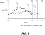
- FIG. 3 is a diagram for explaining the total quantity QA_RTn.
- candidates RT1, RT2, and RT3 are drawn as the candidates RTn of the route. These candidates are all candidates of three routes from a current location CL of the vehicle 1 to a destination DS of the vehicle 1.
- the time Tcl shown on the horizontal axis of FIG. 3 represents the current time.
- times 11, T2, and T3 represent the times at which vehicle 1 arrives at destination DS when the vehicle 1 travels along the candidates RT1, RT2, and RT3, respectively.
- the vertical axis of FIG. 3 represents a generated quantity per unit time ⁇ QA_RTn of the log data LOG.
- the generated quantity ⁇ QA_RTn differs among the candidates RT1 to RT3. This is because at least a part of the routes is different among the candidates RT1 to RT3. This is because, if at least a part of the routes is different, a difference occurs in a frequency or a difficulty of an event (e.g., a recognition event of an object, a generation event of a driving plan, a calculation event of a control amount, or the like) in which the log data LOG is generated.
- an event e.g., a recognition event of an object, a generation event of a driving plan, a calculation event of a control amount, or the like
- the higher the frequency of events per unit time the larger the generated quantity ⁇ QA-RTn.
- the higher the difficulty level of the event the more the generated quantity AQA_RTn.
- the total quantity QA_RT1 of the log data LOG generated during the travel of the vehicle 1 along the candidate RT1 is represented by the value ⁇ QA_t1dt obtained by integrating the generated quantity ⁇ QA_RT1 from the time Tcl to the time RT1.
- the total quantity QA_RT2 is represented by a value ⁇ QA_t2dt obtained by integrating the generated quantity ⁇ QA_RT2 from the time Tcl to the time RT2.
- the total quantity QA_RT3 is represented by a value ⁇ QA_t3dt obtained by integrating the generated quantity ⁇ QA_RT3 from the time Tcl to the time RT3.
- the future value QC_RTn (Tds) of the free space QC at the time of an arrival at the destination DS is calculated based on the total quantity QA_RTn.
- the future value QC_RTn (Tds) can be expressed by the following Equation (1) using the value of the free space QC at the time Tcl (i.e., the current value) QC (Tcl).
- QC _ RTn Tds QC Tcl ⁇ ⁇ ⁇ QA _ RTndt
- the candidate RTn that maximizes the future value QC_RTn (Tds) calculated by Equation (1) is selected as the autonomous driving route. If the candidate RTn of which the future value QC_RTn (Tds) is the maximum, it is possible to avoid a situation where the free space QC is congested on the way to the destination DS. In the example of FIG. 3 , the total quantity QA_RT2 is the minimum. Therefore, the candidate RTn having the maximum future value QC_RTn (Tds) calculated by Equation (1) is the candidate RT2, and this is selected as the autonomous driving route.
- the fluctuation amount of the log data LOG in the memory device 120 is represented by the total quantity QA_RTn.
- a communication spot e.g., a charging or refueling spot, a service area on the expressway, etc.
- the log data LOG may be transmitted to the management server 200 on the way to the destination DS.
- the transmitted log data LOG can be compressed and stored in the memory device 120, or the transmitted log data LOG can be deleted from the memory device 120.
- FIG. 4 is a diagram showing an example of a transition of the total quantity Qlog of the log data LOG in the memory device 120 when the transmitted log data LOG is compressed or deleted.
- log data LOG is transmitted to the management server 200 during the travel along the candidate RTn.
- the transmitted log data LOG is compressed and stored in the memory device 120.
- the total quantity Qlog is decreased by the data quantity QB_RTn, while the free space QC of the memory device 120 is increased. Therefore, when the communication spot is included on the candidate RTn or in the vicinity of the candidate RTn, the future value QC_RTn (Tds) can be expressed by the following Equation (2).
- QC _ RTn Tds QC Tcl ⁇ ⁇ ⁇ QA _ RTndt + QB _ RTn
- the candidate RTn having the maximum future value QC_RTn (Tds) calculated by Equation (2) is selected as the autonomous driving route.
- the fluctuation amount of the log data LOG in the memory device 120, which fluctuates during the travel along the candidate RTn can be expressed by a combination of the total quantity QA_RTn and the data quantity QB_RTn.
- the candidate RTn having the maximum future value QC_RTn (Tds) is selected as the autonomous driving route. Therefore, it is possible to avoid a situation in which the free space QC is tight during the traveling of the vehicle 1 along the autonomous driving route.
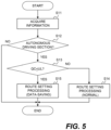
- FIG. 5 is a flow diagram illustrating a processing flow executed by the processing circuitry 110, particularly related to the present embodiment.
- the routine shown in FIG. 5 is repeatedly executed at a predetermined control cycle.
- step S11 various kinds of information are acquired (step S11).
- the information acquired in the processing of step S11 include information of the actual position of the vehicle 1 (latitude and longitude information), map information, and information of the free space QC of the memory device 120.
- step S12 it is determined whether the vehicle 1 is located in a section where the autonomous driving is permitted.
- the determination in step S12 is executed based on, for example, the information of the actual position of the vehicle 1 acquired in step S11 and the map information.
- the judgment result in step S12 is negative, it can be determined that autonomous driving control is not executed. Therefore, in this case, the process is terminated.
- step S12 If the judgment result in step S12 is positive, it can be determined that the autonomous driving control is executed. Therefore, it is determined whether the current value QC (Tcl) of the free space QC of the memory device 120 is equal to or less than an upper limit value UL (step S13).
- the value of the free space QC acquired in step S11 is used as the current value QC (Tcl).
- the upper limit value UL is preset, for example, as an average amount of log data LOG that occurs during one trip.
- the average amount of log data LOG may be an average amount for one or more vehicles 1 or an average amount for the vehicle 1 in which the processing circuitry 110 is mounted.
- step S15 the route setting processing (data-saving) is executed (step S15).
- the candidate RTn is set by the first or second example described above, and the total quantity QA_RTn of the log data LOG generated during the travel of the vehicle 1 along the candidate RTn (see the first and second examples) and the data quantity QB_RTn of the log data LOG decreased during the travel of the vehicle 1 along the candidate RTn (see the second example) are predicted. Then, the candidate RTn having the maximum future value QC_RTn (Tds) calculated based on Equation (1) or (2) is selected as the autonomous driving route.
- step S13 is not essential to the present disclosure. Therefore, when the judgment result in step S12 is positive, the process in step S13 may be skipped and the process in step S15 may be executed. In the processing of step S15, before calculating the future value QC_RTn (Tds), a midway value QA_RTn (Tmw) of the log data LOG generated during the travel of the vehicle 1 along the candidate RTn may be calculated. Further, the candidate RTn may be narrowed down based on the midway value QA_RTn (Tmw).
- FIG. 6 is a diagram for explaining the midway value QA_RTn (Tmw).
- FIG. 6 illustrates the candidate RT1 described in FIG. 3 .
- the total quantity QA_RT1 of the log data LOG generated during the travel of the vehicle 1 along the candidate RT1 is the value ⁇ QA_t1dt obtained by integrating the generated quantity ⁇ QA_RT1 from the time Tcl to the time RT1.
- the midway value QA_RTn (Tmw) is a total quantity of the log data LOG generated by a time (time t4 in the example of FIG. 6 ) before the vehicle 1 reaches the destination DS.
- the value of the free space QC at a time Tmw (i.e., the midway value) may be calculated based on the midway value QA_RTn (Tmw).
- the midway value QC _ RTn (Tmw) in this case can be expressed by the following Equation (3).
- QC _ RTn Tmw QC Tcl ⁇ QA _ RTn Tmw
- the midway value QC_RTn (Tmw) may be further compared with an allowable value AC.
- the allowable value AC is set to, for example, zero or a value close to zero.
- the candidate RTn is excluded from the candidates of the autonomous driving route.
- Such a candidate RTn may be considered to be in a situation where the free space QC is congested on the way to the destination DS. Therefore, according to the example of narrowing down the candidate RTn based on the midway value QA_RTn (Tmw), it is possible to achieve more reliably the effect of the present embodiment of avoiding a situation in which the free space QC is tight.
Landscapes
- Engineering & Computer Science (AREA)
- Radar, Positioning & Navigation (AREA)
- Remote Sensing (AREA)
- Automation & Control Theory (AREA)
- Physics & Mathematics (AREA)
- General Physics & Mathematics (AREA)
- Human Computer Interaction (AREA)
- Transportation (AREA)
- Mechanical Engineering (AREA)
- Traffic Control Systems (AREA)
- Navigation (AREA)
Abstract
An autonomous driving route along which autonomous driving control of a vehicle (1) is executed is set. In the setting of the autonomous driving route, at least two candidates of a route (RTn) from a current location to a destination of the vehicle are set. Next, for each of the at least two candidates, a fluctuation amount of log data that fluctuates in a memory device (120) during a travel of the vehicle along the candidate of the route. Next, a future value of a free space in the memory device at which the vehicle arrives at a destination of the candidate of the route (QC_RTn (Tds)) for each of the at least two candidates based on the fluctuation amount of the log data. Then, one candidate of the route from the at least two candidates of which the future value of the free space is the maximum is selected as the autonomous driving route.
Description
- The present disclosure relates to a system for autonomous driving control of a vehicle.
- In recent years, the development of an autonomous driving technique for controlling a vehicle from data of sensors or the like mounted on the vehicle using models generated through a machine learning (machine learning models) has been advanced.
WO2019/116423A proposes a method to collect training data for use in generating the machine learning models. - Examples of documents indicating a technical level of the art relevant to the present disclosure include
JP2011113494A JP2021146770A JP6761002B WO2019/116423A . - Following is a list of patent literatures which the applicant has noticed as related arts of the present invention.
-
WO2019/116423A -
JP2011113494A -
JP2021146770A -
JP6761002B - It is desirable that autonomous driving control of a vehicle executed using the machine learning models be verified later. As a method for enabling this verification, it is conceivable to store in a memory device of the vehicle log data related to the autonomous driving control of the vehicle. However, a capacity of the memory device of the vehicle is limited. Therefore, when the data quantity of the stored log data reaches a certain value or more, the stored log data may be transmitted to an outside of the vehicle and deleted from the memory device. However, during the execution of the autonomous driving control, log data related to the autonomous driving control is generated every moment. Therefore, when a free space of the memory device is filled with the log data before being transmitted to the outside and the log data generated during the autonomous driving control, the latter log data may not be stored from the middle of the autonomous driving control. Therefore, it is desired to develop a technique for avoiding such a tight situation.
- An object of the present disclosure is to provide a technique that can prevent a situation in which the free space of the memory device of the vehicle in which the autonomous driving control using machine learning models is executed is filled with log data related to the autonomous driving control.
- The present disclosure is an autonomous driving system mounted on a vehicle and has the following features.
- The autonomous driving system comprises one or more processing circuitries and one or more memory devices.
- The one or more processing circuitries are configured to:
- set an autonomous driving route indicating a route of the vehicle on which autonomous driving control of the vehicle is executed; and
- store log data related to the autonomous driving control in the one or more memory devices while the vehicle is traveling along the autonomous driving route.
- In the setting of the autonomous driving route, the one or more processing circuitries are configured to:
- set at least two candidates for a route from a current location of the vehicle to a destination of the vehicle;
- predict for each of the at least two candidates of the route a fluctuation amount of the log data that fluctuates in the one or more memory devices during the travel of the vehicle along the candidate of the route;
- predict a future value of a free space in the one or more memory devices at which the vehicle arrives at a destination of the candidate of the route for each of the at least two candidates of the route based on the fluctuation amount of the log data predicted for each of the at least two candidates of the route; and
- select as the autonomous driving route one candidate of the route from the at least two candidates of the route of which the future value of the free space is the maximum.
- According to the present disclosure, the fluctuation amount of the log data that fluctuates in the one or more memory devices during the travel of the vehicle along the candidate of the route is predicted for each of the at least two candidates of the route. Further, based on the predicted fluctuation amount, the future value of the free space in the one or more memory devices at which the vehicle arrives at the destination of the candidate of the route is predicted for each of the at least two candidates of the route. Then, one candidate of the route from the at least two candidates of the route of which the future value of the free space is the maximum is selected as the route of the vehicle along which the autonomous driving control is executed (i.e., the autonomous driving route). Therefore, according to the present disclosure, it is possible to prevent the situation in which the free space of the memory device of the vehicle in which the autonomous driving control using machine learning models is executed is filled with log data related to the autonomous driving control.
-
-
FIG. 1 is a block diagram illustrating an example of a configuration related to autonomous driving control of a vehicle according to an embodiment; -
FIG. 2 is a conceptual diagram illustrating a configuration example of an autonomous driving system according to the embodiment; -
FIG. 3 is a diagram illustrating an example of an instruction related to a management of log data; -
FIG. 4 is a diagram for explaining a storage time for extracting and storing the log data; -
FIG. 5 is a flow chart illustrating a processing flow executed by a processing circuitry, particularly in relation the embodiment; and -
FIG. 6 is a flowchart illustrating a processing flow executed by the processing circuitry, particularly in relation to the embodiment. -
FIG. 1 is a block diagram illustrating a configuration example related to autonomous driving control of avehicle 1 according to the present embodiment. The autonomous driving is to automatically execute at least one of steering, acceleration, and deceleration of thevehicle 1 without depending on a driving operation by an operator. The autonomous driving control is a concept including not only complete autonomous driving control but also risk avoidance control, lane keep assist control, and the like. The operator may be a driver riding in thevehicle 1 or a remote operator who remotely operates thevehicle 1. - The
vehicle 1 includessensors 10, arecognition portion 20, aplanning portion 30, a controlamount calculation portion 40, and adriving device 50. - The
sensors 10 include arecognition sensor 11 used for recognizing a situation around thevehicle 1. Examples of therecognition sensor 11 include a camera, a laser imaging detection and ranging (LIDAR), and a radar. Thesensors 10 may further include astate sensor 12 that detects a state of thevehicle 1, aposition sensor 13 that detects a position of thevehicle 1, and the like. Examples of thestate sensor 12 include a speed sensor, an acceleration sensor, a yaw rate sensor, and a steering angle sensor. Examples of theposition sensor 13 include a global navigation satellite system (GNSS) sensor. - The information on sensor detection SEN is information obtained by the
sensors 10. For example, the information on sensor detection SEN includes an image captured by the camera. As another example, the information on sensor detection SEN may include point group information obtained by the LIDAR. The information on sensor detection SEN may include vehicle status information indicating the status of thevehicle 1. The information on sensor detection SEN may include positional information indicating the position of thevehicle 1. - The
recognition portion 20 receives information on sensor detection SEN. Therecognition portion 20 recognizes the surrounding situation of thevehicle 1 based on the information obtained by therecognition sensor 11. For example, therecognition portion 20 recognizes an object around thevehicle 1. Examples of the object include a walker, other vehicles (e.g., a preceding vehicle, a parking vehicle, and the like), a white lane, road construction (e.g., a guard rail, a curb), a fallen object, a traffic light, an intersection, a mark, and the like. The information on recognition result RES indicates a recognition result by therecognition portion 20. For example, the information on recognition result RES includes object information indicating a relative position and a relative speed of the object with respect to thevehicle 1. - The planning
portion 30 receives the information on recognition result RES from therecognition portion 20. In addition, the planningportion 30 may receive vehicle status information, positional information, and pre-generated map information. The map information may be high-precision three-dimensional map information. The planningportion 30 generates a driving plan of thevehicle 1 based on the received information. The driving plan may be the one to reach a destination set in advance or the one to avoid a risk. Examples of the driving plan include maintaining a current traveling lane, changing lanes, taking an overtake, turning right or left, steering, accelerating, decelerating, and stopping. Further, the planningportion 30 generates a target trajectory TRJ required for thevehicle 1 to travel in accordance with the driving plan. The target trajectory TRJ includes a target position and a target speed. - The control
amount calculation portion 40 receives the target trajectory TRJ from the planningportion 30. The controlamount calculation portion 40 calculates a control amount CON required for thevehicle 1 to follow the target trajectory TRJ. The control amount CON may be a control amount required to reduce a deviation between thevehicle 1 and the target trajectory TRJ. The control amount CON includes at least one of a steering control amount, a drive control amount, and a braking control amount. Examples of the steering control amount include a target steering angle, a target torque, a target motor angle, and a target motor drive current. Examples of the drive control amount include target speed, target acceleration, and the like. Examples of the braking control amount include target speed, target deceleration, and the like. - The driving
device 50 includes asteering device 51, a drivingdevice 52, and abraking device 53. Thesteering device 51 steers the wheels. For example, thesteering device 51 includes an electric power steering (EPS) device. The drivingdevice 52 is a power source that generates a driving force. Examples of the drivingdevice 52 include an engine, an electric motor, and an in-wheel motor. Thebraking device 53 generates a braking force. The drivingdevice 50 receives the control amount CON from the controlamount calculation portion 40. The drivingdevice 50 operates thesteering device 51, the drivingdevice 52, and thebraking device 53 in accordance with the steering control amount, the drive control amount, and the braking control amount, respectively. As a result, thevehicle 1 travels so as to follow the target trajectory TRJ. - The
recognition portion 20 may include at least one of rule-based models and machine learning models. The rule-based models execute recognition processing based on a predetermined rule group. Examples of the machine learning models include a neural network (NN), a support vector machine (SVM), a regression model, and a decision tree model. The NN may be a convolutional neural network (CNN), a recurrent neural network (RNN), or a combination thereof. The type of each layer, the number of layers, and the number of nodes in the NN are arbitrary. The machine learning models are generated in advance through machine learning. Therecognition portion 20 executes recognition processing by inputting information on sensor detection (SEN) to the models. The information on recognition result RES is output from the models or generated based on the output from the models. - The planning
portion 30 may also include at least one of rule-based models and machine learning models. The planningportion 30 executes planning processing by inputting the information on recognition result RES to the models. The target trajectory TRJ is output from the model or generated based on the output from the models. - The control
amount calculation portion 40 also includes at least one of rule-based models and machine learning models. The controlamount calculation portion 40 executes control amount calculation processing by inputting the target trajectory TRJ to the models. The control amount CON is output from the model or generated based on the output from the models. - Two or more of the
recognition portions 20, the planningportion 30, and the controlamount calculation portion 40 may be integrally configured. All of therecognition portion 20, the planningportion 30, and the controlamount calculation portion 40 may be integrally configured (End-to-End configuration). For example, therecognition portion 20 and theplanning portion 30 may be integrally configured by the NN that outputs the target trajectory TRJ from the information on sensor detection SEN. Even in the case of the integrated configuration, an intermediate product such as the information on recognition result RES or the target trajectory TRJ may be output. For example, when therecognition portion 20 and theplanning portion 30 are integrally configured by the NN, the information on recognition result RES may be an output of an intermediate layer of the NN. - The
recognition portion 20, the planningportion 30, and the controlamount calculation portion 40 constitute an "autonomous driving control portion" that controls the autonomous driving of thevehicle 1. In the present embodiment, the machine learning models are used for at least a part of the autonomous driving control portion. That is, at least one of therecognition portion 20, the planningportion 30, and the controlamount calculation portion 40 may include the machine learning models. The autonomous driving control portion executes at least a portion of the autonomous driving control of thevehicle 1 using the machine learning models. -
FIG. 2 is a conceptual diagram illustrating a configuration example of theautonomous driving system 100 according to the present embodiment. Theautonomous driving system 100 is mounted on thevehicle 1 and executes the autonomous driving control of thevehicle 1. Theautonomous driving system 100 has at least the function of the autonomous driving control portion described above. Theautonomous driving system 100 may further include thesensors 10 and the drivingdevice 50. - The
autonomous driving system 100 includes one or more processing circuitries 110 (hereinafter, simply referred to as a "processing circuitry" 110) and one or more memory devices 120 (hereinafter, simply referred to as a "memory device 120"). Theprocessing circuitry 110 executes various processing. Examples of theprocessing circuitry 110 include a central processing unit (CPU), a graphics processing unit (GPU), an application specific integrated circuit (ASIC), and a field-programmable gate array (FPGA). Therecognition portion 20, the planningportion 30, and the controlamount calculation portion 40 may be implemented by asingle processing circuitry 110 or may be implemented byseparate processing circuitry 110. Thememory device 120 stores various information. Examples of thememory device 120 include a hard disk drive (HDD), a solid-state drive (SSD), a volatile memory, and a nonvolatile memory. - The
program 130 is a computer program for controlling thevehicle 1, and is executed by theprocessing circuitry 110. Various processes by theautonomous driving system 100 may be realized by cooperation of theprocessing circuitry 110 that executes theprogram 130 and thememory device 120. Theprogram 130 is stored in thememory device 120. Theprogram 130 may be recorded in a computer-readable recording medium. - The
model data 140 is data of a model included in therecognition portion 20, the planningportion 30, and the controlamount calculation portion 40. As described above, in the present embodiment, at least one of therecognition portion 20, the planningportion 30, and the controlamount calculation portion 40 includes the "machine learning models". Themodel data 140 is stored in thememory device 120 and used for the autonomous driving control. - During the autonomous driving control, the
processing circuitry 110 obtains "log data LOG" associated with the autonomous driving control. The log data LOG may include information on sensor detection SEN input to the autonomous driving control portion. The log data LOG may include a control amount CON output from the autonomous driving control portion. The log data LOG may include information on recognition result RES output from therecognition portion 20. The log data LOG may include the target trajectory TRJ output from the planningportion 30. The log data LOG may include a reason for determination in the recognition processing by therecognition portion 20. The log data LOG may include a reason for determination in the planning processing by the planningportion 30. The log data LOG may include the presence or absence of an operator intervention for the autonomous driving control. - The
processing circuitry 110 stores the log data LOG acquired during the autonomous driving control in thememory device 120. Theprocessing circuitry 110 may temporarily store the log data LOG in thememory device 120 for a certain period. - The
management server 200 is an external device that exists outside thevehicle 1. Themanagement server 200 communicates with one ormore vehicles 1 via a communication network. During the autonomous driving control or after the autonomous driving control is terminated, theprocessing circuitry 110 of thevehicle 1 may upload at least a part of the log data LOG stored in thelocal memory device 120 to themanagement server 200. The log data LOG uploaded to themanagement server 200 is used for verification of autonomous driving control using machine learning models. Theprocessing circuitry 110 may delete the log data LOG uploaded to themanagement server 200 from thelocal memory device 120. - In the present embodiment, a case is considered where the autonomous driving control of the
vehicle 1 is executed in a section where autonomous driving is possible (e.g., a section of an expressway, a section dedicated to an autonomous driving, or the like). In this case, a route of thevehicle 1 on which the autonomous driving control is executed (hereinafter, also referred to as an "autonomous driving route") is set. Setting processing of the autonomous driving route (hereinafter, also referred to as "route setting processing") may be executed by theprocessing circuitry 110 or may be executed by a processing circuitry (e.g., a processing circuitry of a navigation system) other than theprocessing circuitry 110 mounted on thevehicle 1. - While the
vehicle 1 is traveling along the autonomous driving route, the log data LOG is generated in accordance with the execution of the autonomous driving control. The generated log data LOG is stored in thememory device 120 of thevehicle 1. Here, during the execution of the autonomous driving control, the log data LOG continues to be generated. Therefore, a total quantity Qlog of the log data LOG in thememory device 120 continues to increase, while a free space QC of thememory device 120 continues to decrease. As a result, when the free space QC is tight, there is a possibility that the log data LOG generated during the traveling of thevehicle 1 along the autonomous driving route cannot be stored from the middle of the autonomous driving route. - In view of this problem, in the route setting processing, at least two candidate RTs n of the autonomous driving route are set (n≥2). In the route setting processing, the total quantity QA_RTn of the log data LOG generated during the traveling of the
vehicle 1 along the candidate RTn is predicted.FIG. 3 is a diagram for explaining the total quantity QA_RTn. InFIG. 3 , candidates RT1, RT2, and RT3 are drawn as the candidates RTn of the route. These candidates are all candidates of three routes from a current location CL of thevehicle 1 to a destination DS of thevehicle 1. The time Tcl shown on the horizontal axis ofFIG. 3 represents the current time. Further,times 11, T2, and T3 represent the times at whichvehicle 1 arrives at destination DS when thevehicle 1 travels along the candidates RT1, RT2, and RT3, respectively. - The vertical axis of
FIG. 3 represents a generated quantity per unit time ΔQA_RTn of the log data LOG. As shown inFIG. 3 , the generated quantity ΔQA_RTn differs among the candidates RT1 to RT3. This is because at least a part of the routes is different among the candidates RT1 to RT3. This is because, if at least a part of the routes is different, a difference occurs in a frequency or a difficulty of an event (e.g., a recognition event of an object, a generation event of a driving plan, a calculation event of a control amount, or the like) in which the log data LOG is generated. In general, the higher the frequency of events per unit time, the larger the generated quantity ΔQA-RTn. Further, the higher the difficulty level of the event, the more the generated quantity AQA_RTn. - The total quantity QA_RT1 of the log data LOG generated during the travel of the
vehicle 1 along the candidate RT1 is represented by the value ∫ΔQA_t1dt obtained by integrating the generated quantity ΔQA_RT1 from the time Tcl to the time RT1. The total quantity QA_RT2 is represented by a value ∫ΔQA_t2dt obtained by integrating the generated quantity ΔQA_RT2 from the time Tcl to the time RT2. The total quantity QA_RT3 is represented by a value ∫ΔQA_t3dt obtained by integrating the generated quantity ΔQA_RT3 from the time Tcl to the time RT3. - In the route setting processing, further, the future value QC_RTn (Tds) of the free space QC at the time of an arrival at the destination DS (an arrival time Tds) is calculated based on the total quantity QA_RTn. The future value QC_RTn (Tds) can be expressed by the following Equation (1) using the value of the free space QC at the time Tcl (i.e., the current value) QC (Tcl).

- In the first example of the route setting processing, the candidate RTn that maximizes the future value QC_RTn (Tds) calculated by Equation (1) is selected as the autonomous driving route. If the candidate RTn of which the future value QC_RTn (Tds) is the maximum, it is possible to avoid a situation where the free space QC is congested on the way to the destination DS. In the example of
FIG. 3 , the total quantity QA_RT2 is the minimum. Therefore, the candidate RTn having the maximum future value QC_RTn (Tds) calculated by Equation (1) is the candidate RT2, and this is selected as the autonomous driving route. - In the example of calculating the future value QC_RTn (Tds) described with reference to
FIG. 3 , the fluctuation amount of the log data LOG in thememory device 120, which fluctuates during the travel along the candidate RTn, is represented by the total quantity QA_RTn. However, if a communication spot (e.g., a charging or refueling spot, a service area on the expressway, etc.) is included on the candidate RTn or in the vicinity of the candidate RTn, the log data LOG may be transmitted to themanagement server 200 on the way to the destination DS. In this case, the transmitted log data LOG can be compressed and stored in thememory device 120, or the transmitted log data LOG can be deleted from thememory device 120. -
FIG. 4 is a diagram showing an example of a transition of the total quantity Qlog of the log data LOG in thememory device 120 when the transmitted log data LOG is compressed or deleted. In the example shown inFIG. 4 , log data LOG is transmitted to themanagement server 200 during the travel along the candidate RTn. The transmitted log data LOG is compressed and stored in thememory device 120. As a result, the total quantity Qlog is decreased by the data quantity QB_RTn, while the free space QC of thememory device 120 is increased. Therefore, when the communication spot is included on the candidate RTn or in the vicinity of the candidate RTn, the future value QC_RTn (Tds) can be expressed by the following Equation (2).
- In the second example of the route setting processing, the candidate RTn having the maximum future value QC_RTn (Tds) calculated by Equation (2) is selected as the autonomous driving route. In this way, the fluctuation amount of the log data LOG in the
memory device 120, which fluctuates during the travel along the candidate RTn, can be expressed by a combination of the total quantity QA_RTn and the data quantity QB_RTn. - As described above, according to the first or second example, the candidate RTn having the maximum future value QC_RTn (Tds) is selected as the autonomous driving route. Therefore, it is possible to avoid a situation in which the free space QC is tight during the traveling of the
vehicle 1 along the autonomous driving route. -
FIG. 5 is a flow diagram illustrating a processing flow executed by theprocessing circuitry 110, particularly related to the present embodiment. The routine shown inFIG. 5 is repeatedly executed at a predetermined control cycle. - In the routine shown in
FIG. 5 , first, various kinds of information are acquired (step S11). Examples of the information acquired in the processing of step S11 include information of the actual position of the vehicle 1 (latitude and longitude information), map information, and information of the free space QC of thememory device 120. - Subsequent to the processing of step S11, it is determined whether the
vehicle 1 is located in a section where the autonomous driving is permitted (step S12). The determination in step S12 is executed based on, for example, the information of the actual position of thevehicle 1 acquired in step S11 and the map information. When the judgment result in step S12 is negative, it can be determined that autonomous driving control is not executed. Therefore, in this case, the process is terminated. - If the judgment result in step S12 is positive, it can be determined that the autonomous driving control is executed. Therefore, it is determined whether the current value QC (Tcl) of the free space QC of the
memory device 120 is equal to or less than an upper limit value UL (step S13). In the processing of step S13, the value of the free space QC acquired in step S11 is used as the current value QC (Tcl). The upper limit value UL is preset, for example, as an average amount of log data LOG that occurs during one trip. The average amount of log data LOG may be an average amount for one ormore vehicles 1 or an average amount for thevehicle 1 in which theprocessing circuitry 110 is mounted. - If the judgment result in step S13 is negative, the route setting processing (normal) is executed (step S14). In the processing of step S14, the autonomous driving route from the current location C L to the destination DS of the
vehicle 1 is set based on aspects other than the log data LOG. As the aspects other than log data LOG, a time required to reach the destination DS, a driving distance, fees, and the like are exemplified. - If the judgment result in step S13 is positive, the route setting processing (data-saving) is executed (step S15). In the processing of step S15, the candidate RTn is set by the first or second example described above, and the total quantity QA_RTn of the log data LOG generated during the travel of the
vehicle 1 along the candidate RTn (see the first and second examples) and the data quantity QB_RTn of the log data LOG decreased during the travel of thevehicle 1 along the candidate RTn (see the second example) are predicted. Then, the candidate RTn having the maximum future value QC_RTn (Tds) calculated based on Equation (1) or (2) is selected as the autonomous driving route. - The processing in step S13 is not essential to the present disclosure. Therefore, when the judgment result in step S12 is positive, the process in step S13 may be skipped and the process in step S15 may be executed. In the processing of step S15, before calculating the future value QC_RTn (Tds), a midway value QA_RTn (Tmw) of the log data LOG generated during the travel of the
vehicle 1 along the candidate RTn may be calculated. Further, the candidate RTn may be narrowed down based on the midway value QA_RTn (Tmw). -
FIG. 6 is a diagram for explaining the midway value QA_RTn (Tmw).FIG. 6 illustrates the candidate RT1 described inFIG. 3 . As described in the description ofFIG. 3 , the total quantity QA_RT1 of the log data LOG generated during the travel of thevehicle 1 along the candidate RT1 is the value ∫ΔQA_t1dt obtained by integrating the generated quantity ΔQA_RT1 from the time Tcl to the time RT1. The midway value QA_RTn (Tmw) is a total quantity of the log data LOG generated by a time (time t4 in the example ofFIG. 6 ) before thevehicle 1 reaches the destination DS. - When the midway value QA_RTn (Tmw) is calculated in the processing of step S15, the value of the free space QC at a time Tmw (i.e., the midway value) may be calculated based on the midway value QA_RTn (Tmw). The midway value QC _ RTn (Tmw) in this case can be expressed by the following Equation (3).

- When the midway value QC_RTn (Tmw) is calculated, the midway value QC_RTn (Tmw) may be further compared with an allowable value AC. The allowable value AC is set to, for example, zero or a value close to zero. As a result of the comparison, when there is a candidate RTn whose midway value QC _ RTn (Tmw) is equal to or less than the allowable value AC, the candidate RTn is excluded from the candidates of the autonomous driving route. Such a candidate RTn may be considered to be in a situation where the free space QC is congested on the way to the destination DS. Therefore, according to the example of narrowing down the candidate RTn based on the midway value QA_RTn (Tmw), it is possible to achieve more reliably the effect of the present embodiment of avoiding a situation in which the free space QC is tight.
Claims (4)
- An autonomous driving system (100) mounted on a vehicle (1), comprising:one or more processing circuitries (110); andone or more memory devices (120),wherein the one or more processing circuitries are configured to:set an autonomous driving route indicating a route of the vehicle on which autonomous driving control of the vehicle is executed; andstore log data (LOG) related to the autonomous driving control in the one or more memory devices while the vehicle is traveling along the autonomous driving route,
wherein, in the setting of the autonomous driving route, the one or more processing circuitries are configured to:
set at least two candidates for a route (RTn) from a current location of the vehicle to a destination of the vehicle;predict for each of the at least two candidates of the route a fluctuation amount of the log data that fluctuates in the one or more memory devices during the travel of the vehicle along the candidate of the route;predict a future value of a free space in the one or more memory devices at which the vehicle arrives at a destination of the candidate of the route (QC_RTn (Tds)) for each of the at least two candidates of the route based on the fluctuation amount of the log data predicted for each of the at least two candidates of the route; andselect as the autonomous driving route one candidate of the route from the at least two candidates of the route of which the future value of the free space is the maximum. - The autonomous driving system according to claim 1,wherein, in the setting of the autonomous driving route, the one or more processing circuitries are configured to determine whether a current value of the free space (QC (Tcl)) is equal to or less than an upper limit value (UL),wherein the prediction of the fluctuation amount of the log data and the prediction of the future value of the free space are executed when it is determined that the current value of the free space is equal to or less than the upper limit value.
- The autonomous driving system according to claim 1 or 2,
wherein, in the prediction of the fluctuation amount of the log data, the one or more processing circuitries are configured to:calculate, for each of the at least two candidates of the route, a total quantity of the log data (QA_RTn) which is generated during the travel of the vehicle along the candidate of the route and a data quantity of the log data in the one or more memory devices (QB_RTn) which is decreased during the travel of the vehicle; andcalculate, for each of the at least two candidates of the route, the fluctuation of the log data by adding the total quantity of the log data generated during the travel of the vehicle and the data quantity of the log data decreased in the one or more memory devices during the travel of the vehicle. - The autonomous driving system according to claim 1 or 2,
wherein, in the setting of the autonomous driving route, the one or more processing circuitries are further configured to:calculate, for each of the at least two candidates of the route, a generate quantity per unit time of the log data (ΔQA_RTn) which is generated during the travel of the vehicle along the candidate of the route;predict, for each of the at least two candidates of the route, a midway value indicating a value of the free space on the way to the destination of the vehicle (QA_RTn (Tmw)) based on a current value of the free space and an integrated value of the generated quantity per unit time; andexclude, from the at least two candidates of the route, a candidate of the route of which the midway value is equal to or less than an allowable value (AC).
Applications Claiming Priority (1)
| Application Number | Priority Date | Filing Date | Title |
|---|---|---|---|
| JP2023113256A JP2025010940A (en) | 2023-07-10 | 2023-07-10 | Autonomous Driving System |
Publications (1)
| Publication Number | Publication Date |
|---|---|
| EP4492345A1 true EP4492345A1 (en) | 2025-01-15 |
Family
ID=91128340
Family Applications (1)
| Application Number | Title | Priority Date | Filing Date |
|---|---|---|---|
| EP24176026.3A Pending EP4492345A1 (en) | 2023-07-10 | 2024-05-15 | Autonomous driving system |
Country Status (3)
| Country | Link |
|---|---|
| US (1) | US12594962B2 (en) |
| EP (1) | EP4492345A1 (en) |
| JP (1) | JP2025010940A (en) |
Families Citing this family (2)
| Publication number | Priority date | Publication date | Assignee | Title |
|---|---|---|---|---|
| JP2025010803A (en) * | 2023-07-10 | 2025-01-23 | トヨタ自動車株式会社 | Control System |
| KR20250117176A (en) * | 2024-01-26 | 2025-08-04 | 삼성전자주식회사 | Storage device for storing autonomous driving analysis data and method of operation the same |
Citations (7)
| Publication number | Priority date | Publication date | Assignee | Title |
|---|---|---|---|---|
| JP2011113494A (en) | 2009-11-30 | 2011-06-09 | Canon Inc | Log acquisition control in log audit system |
| JP2019056559A (en) * | 2017-09-19 | 2019-04-11 | 株式会社デンソー | Route search device |
| WO2019116423A1 (en) | 2017-12-11 | 2019-06-20 | 本田技研工業株式会社 | Teacher data collection device |
| JP6761002B2 (en) | 2018-07-23 | 2020-09-23 | ファナック株式会社 | Data management device, data management program and data management method |
| JP2021146770A (en) | 2020-03-16 | 2021-09-27 | いすゞ自動車株式会社 | Vehicle control device, vehicle, and vehicle control method |
| US20230056115A1 (en) * | 2021-08-18 | 2023-02-23 | Aptiv Technologies Limited | Method of Collecting Data from Fleet of Vehicles |
| US20230119474A1 (en) * | 2020-06-22 | 2023-04-20 | Denso Corporation | Data collection system, collection center and data collection method |
Family Cites Families (5)
| Publication number | Priority date | Publication date | Assignee | Title |
|---|---|---|---|---|
| CN106163862B (en) * | 2014-04-04 | 2019-07-05 | 特斯拉公司 | Method and computer-readable storage medium for trip planning |
| WO2018126079A1 (en) * | 2016-12-30 | 2018-07-05 | DeepMap Inc. | High definition map and route storage management system for autonomous vehicles |
| US11662721B2 (en) * | 2019-09-20 | 2023-05-30 | International Business Machines Corporation | Relative position management of autonomous vehicles based on data bandwith requirements |
| US11657591B2 (en) * | 2021-01-15 | 2023-05-23 | Argo AI, LLC | Autonomous vehicle system for intelligent on-board selection of data for building a remote machine learning model |
| US20240351606A1 (en) * | 2023-04-18 | 2024-10-24 | Gm Cruise Holdings Llc | Autonomous vehicle data prioritization and classification |
-
2023
- 2023-07-10 JP JP2023113256A patent/JP2025010940A/en active Pending
-
2024
- 2024-05-15 EP EP24176026.3A patent/EP4492345A1/en active Pending
- 2024-07-02 US US18/761,875 patent/US12594962B2/en active Active
Patent Citations (7)
| Publication number | Priority date | Publication date | Assignee | Title |
|---|---|---|---|---|
| JP2011113494A (en) | 2009-11-30 | 2011-06-09 | Canon Inc | Log acquisition control in log audit system |
| JP2019056559A (en) * | 2017-09-19 | 2019-04-11 | 株式会社デンソー | Route search device |
| WO2019116423A1 (en) | 2017-12-11 | 2019-06-20 | 本田技研工業株式会社 | Teacher data collection device |
| JP6761002B2 (en) | 2018-07-23 | 2020-09-23 | ファナック株式会社 | Data management device, data management program and data management method |
| JP2021146770A (en) | 2020-03-16 | 2021-09-27 | いすゞ自動車株式会社 | Vehicle control device, vehicle, and vehicle control method |
| US20230119474A1 (en) * | 2020-06-22 | 2023-04-20 | Denso Corporation | Data collection system, collection center and data collection method |
| US20230056115A1 (en) * | 2021-08-18 | 2023-02-23 | Aptiv Technologies Limited | Method of Collecting Data from Fleet of Vehicles |
Also Published As
| Publication number | Publication date |
|---|---|
| US20250018977A1 (en) | 2025-01-16 |
| US12594962B2 (en) | 2026-04-07 |
| JP2025010940A (en) | 2025-01-23 |
Similar Documents
| Publication | Publication Date | Title |
|---|---|---|
| CN112368662B (en) | Directional adjustment actions for autonomous vehicle operation management | |
| JP7347523B2 (en) | Vehicle control device and vehicle control method | |
| EP4492345A1 (en) | Autonomous driving system | |
| RU2671602C1 (en) | Device for forming of a target route and the device for controlling the drive | |
| JP2022052874A (en) | Automated driving apparatus | |
| EP4498340A1 (en) | Autonomous driving system | |
| KR20220108823A (en) | Systems and methods for predicting the trajectory of a vehicle | |
| US20240211046A1 (en) | Vision-Based Road Feel Enhancement in Vehicles | |
| JP7827023B2 (en) | Autonomous Driving System | |
| CN108630002A (en) | Method and apparatus at least one most probable path for determining vehicle | |
| EP4485401A1 (en) | Autonomous driving vehicle | |
| US20250020477A1 (en) | Travel route management system | |
| EP4485402A1 (en) | Autonomous driving vehicle | |
| EP4465263A1 (en) | Method and device for managing vehicle data | |
| US20240391491A1 (en) | Autonomous driving vehicle | |
| EP4491485A1 (en) | Autonomous driving system and control method | |
| JP7635774B2 (en) | Vehicle control device, vehicle control method, and vehicle control computer program | |
| US12330643B2 (en) | Generating and selecting candidate trajectories | |
| EP4484244A1 (en) | Control apparatus, control method, and control program | |
| EP4491484A1 (en) | Log management system and log management method | |
| US20240391492A1 (en) | Method and device for managing vehicle data | |
| CN117799631A (en) | A vehicle driving control method, device, terminal and readable storage medium |
Legal Events
| Date | Code | Title | Description |
|---|---|---|---|
| PUAI | Public reference made under article 153(3) epc to a published international application that has entered the european phase |
Free format text: ORIGINAL CODE: 0009012 |
|
| STAA | Information on the status of an ep patent application or granted ep patent |
Free format text: STATUS: REQUEST FOR EXAMINATION WAS MADE |
|
| 17P | Request for examination filed |
Effective date: 20240515 |
|
| AK | Designated contracting states |
Kind code of ref document: A1 Designated state(s): AL AT BE BG CH CY CZ DE DK EE ES FI FR GB GR HR HU IE IS IT LI LT LU LV MC ME MK MT NL NO PL PT RO RS SE SI SK SM TR |