EP4492344A1 - Automated driving system - Google Patents
Automated driving system Download PDFInfo
- Publication number
- EP4492344A1 EP4492344A1 EP24176021.4A EP24176021A EP4492344A1 EP 4492344 A1 EP4492344 A1 EP 4492344A1 EP 24176021 A EP24176021 A EP 24176021A EP 4492344 A1 EP4492344 A1 EP 4492344A1
- Authority
- EP
- European Patent Office
- Prior art keywords
- detection information
- automated driving
- log data
- recognition result
- vehicle
- Prior art date
- Legal status (The legal status is an assumption and is not a legal conclusion. Google has not performed a legal analysis and makes no representation as to the accuracy of the status listed.)
- Pending
Links
Images


Classifications
-
- G—PHYSICS
- G07—CHECKING-DEVICES
- G07C—TIME OR ATTENDANCE REGISTERS; REGISTERING OR INDICATING THE WORKING OF MACHINES; GENERATING RANDOM NUMBERS; VOTING OR LOTTERY APPARATUS; ARRANGEMENTS, SYSTEMS OR APPARATUS FOR CHECKING NOT PROVIDED FOR ELSEWHERE
- G07C5/00—Registering or indicating the working of vehicles
- G07C5/08—Registering or indicating performance data other than driving, working, idle, or waiting time, with or without registering driving, working, idle or waiting time
- G07C5/0841—Registering performance data
-
- G—PHYSICS
- G07—CHECKING-DEVICES
- G07C—TIME OR ATTENDANCE REGISTERS; REGISTERING OR INDICATING THE WORKING OF MACHINES; GENERATING RANDOM NUMBERS; VOTING OR LOTTERY APPARATUS; ARRANGEMENTS, SYSTEMS OR APPARATUS FOR CHECKING NOT PROVIDED FOR ELSEWHERE
- G07C5/00—Registering or indicating the working of vehicles
- G07C5/02—Registering or indicating driving, working, idle, or waiting time only
-
- G—PHYSICS
- G06—COMPUTING OR CALCULATING; COUNTING
- G06F—ELECTRIC DIGITAL DATA PROCESSING
- G06F11/00—Error detection; Error correction; Monitoring
- G06F11/30—Monitoring
- G06F11/34—Recording or statistical evaluation of computer activity, e.g. of down time, of input/output operation ; Recording or statistical evaluation of user activity, e.g. usability assessment
- G06F11/3466—Performance evaluation by tracing or monitoring
- G06F11/3476—Data logging
-
- G—PHYSICS
- G06—COMPUTING OR CALCULATING; COUNTING
- G06F—ELECTRIC DIGITAL DATA PROCESSING
- G06F17/00—Digital computing or data processing equipment or methods, specially adapted for specific functions
- G06F17/40—Data acquisition and logging
-
- B—PERFORMING OPERATIONS; TRANSPORTING
- B60—VEHICLES IN GENERAL
- B60W—CONJOINT CONTROL OF VEHICLE SUB-UNITS OF DIFFERENT TYPE OR DIFFERENT FUNCTION; CONTROL SYSTEMS SPECIALLY ADAPTED FOR HYBRID VEHICLES; ROAD VEHICLE DRIVE CONTROL SYSTEMS FOR PURPOSES NOT RELATED TO THE CONTROL OF A PARTICULAR SUB-UNIT
- B60W60/00—Drive control systems specially adapted for autonomous road vehicles
-
- G—PHYSICS
- G06—COMPUTING OR CALCULATING; COUNTING
- G06V—IMAGE OR VIDEO RECOGNITION OR UNDERSTANDING
- G06V20/00—Scenes; Scene-specific elements
- G06V20/50—Context or environment of the image
- G06V20/56—Context or environment of the image exterior to a vehicle by using sensors mounted on the vehicle
- G06V20/58—Recognition of moving objects or obstacles, e.g. vehicles or pedestrians; Recognition of traffic objects, e.g. traffic signs, traffic lights or roads
Definitions
- the present disclosure relates to an automated driving system installed on a vehicle.
- Patent Literature 1 discloses a method for collecting training data that can be used for training of a machine learning model.
- Patent Literatures 2 and 3 are documents showing the technical level of the present technical field.
- log data related to the automated driving control As a method for ex-post facto assessment of automated driving control of a vehicle, it is containable to store log data related to the automated driving control in an in-vehicle storage device.
- the capacity of the storage device installed in the vehicle is limited, if the capacity of the storage device is strained, there is a possibility that necessary log data will not be able to be stored.
- the log data of detection information by a recognition sensor that detects information around a vehicle is particularly required for the verification of the automated driving control, but the data amount thereof is likely to be large.
- An object of the present disclosure is, in the view of the above problems, to provide a technique capable of efficiently using the capacity of a storage device.
- One aspect of the present disclosure is directed to an automated driving system installed in a vehicle.
- the automated driving system comprises:
- the one or more processors are further configured to execute a storing process of storing log data of the detection information in the one or more storage devices while performing the automated driving control.
- the one or more processors are configured to:
- the log data of the target detection information that is the detection information related to the low reliability area is preferentially stored.
- the low reliability area is an area around the vehicle where the reliability of the recognition result is low. This allows the capacity of the storage device to be used efficiently from the viewpoint of the high necessity in the verification of the automated driving control.
- FIG. 1 is a diagram showing an example of a configuration related to automated driving control of a vehicle 1 by an automated driving system according to the present embodiment.
- the automated driving is to automatically perform at least one of steering, acceleration, and deceleration of the vehicle 1 without depending on a driving operation performed by an operator.
- the automated driving control is a concept including not only complete automated driving control but also risk avoidance control, lane keep assist control, and the like.
- the operator may be a driver on board the vehicle 1 or may be a remote operator who remotely operates the vehicle 1.
- the vehicle 1 includes a sensor group 10, a recognition unit 20, a planning unit 30, a control amount calculation unit 40, and a travel device 50.
- the sensor group 10 includes a recognition sensor 11 detecting information around the vehicle 1.
- the recognition sensor 11 include a camera, a laser imaging detection and ranging (LIDAR), a radar, and the like.
- the sensor group 10 may further include a state sensor 12 that detects a state of the vehicle 1, a position sensor 13 that detects a position of the vehicle 1, and the like.
- the state sensor 12 include a speed sensor, an acceleration sensor, a yaw rate sensor, a steering angle sensor, and the like.
- GNSS global navigation satellite system
- Sensor detection information SEN is information detected by the sensor group 10.
- the sensor detection information SEN includes image data captured (taken) by the camera.
- the sensor detection information SEN may include information (e.g., relative position, relative velocity, class, and the like) regarding a specific object appearing in the image (e.g., a pedestrian, a preceding vehicle, a white line, a bicycle, a road sign, and the like).
- the sensor detection information SEN may include point cloud data detected by the LIDAR.
- the sensor detection information SEN may include information on a relative position and a relative velocity of objects detected by the radar.
- the sensor detection information SEN may include vehicle state information indicating the state of the vehicle 1.
- the sensor detection information SEN may include position information indicating the position of the vehicle 1.
- the recognition unit 20 receives the sensor detection information SEN.
- the recognition unit 20 recognizes a situation around the vehicle 1 based on the sensor detection information SEN detected by the recognition sensor 11. Also, for example, the recognition unit 20 generates a space map in which the recognized object is integrated into the map information. Examples of the object include a pedestrian, another vehicle (e.g., a preceding vehicle, a parked vehicle, and the like), a white line, a road structure (e.g., a guard rail, a curb, and the like), a fallen object, a traffic light, an intersection, a sign, and the like. Furthermore, the recognition unit 20 may perform prediction of the behavior of an object around the vehicle 1. Recognition result information RES indicates a result of recognition by the recognition unit 20.
- the planning unit 30 receives the recognition result information RES from the recognition unit 20.
- the planning unit 30 generates a travel plan of the vehicle 1 based on the received recognition result information RES.
- the planning unit 30 may further receive the vehicle state information and the position information.
- the travel plan may be one for arriving at a destination set in advance.
- the travel plan may be one for avoiding a risk.
- the travel plan provides driving decisions such as, for example, maintaining a current travel lane, making a lane change, overtaking, making a right or left turn, steering, accelerating, decelerating, stopping, and the like.
- the planning unit 30 generates a target trajectory TRJ required for the vehicle 1 to travel in accordance with the travel plan.
- the target trajectory TRJ includes a target position and a target velocity.
- the control amount calculation unit 40 receives the target trajectory TRJ from the planning unit 30.
- the control amount calculation unit 40 calculates a control amount CON required for the vehicle 1 to follow the target trajectory TRJ. It can be also said that the control amount CON is a control amount required for reducing a deviation of the vehicle 1 from the target trajectory TRJ.
- the control amount CON includes at least one of a steering control amount, a driving control amount, and a braking control amount.
- the steering control amount include a target steering angle, a target steering torque, a target motor angle, a target motor drive current, and the like.
- Examples of the driving control amount include a target driving force, a target engine torque, and the like.
- Examples of the braking control amount include a target braking force, a target braking torque, and the like.
- the travel device 50 includes a steering device 51, a driving device 52, and a braking device 53.
- the steering device 51 steers wheels of the vehicle 1.
- the driving device 52 is a power source that generates a driving force. Examples of the driving device 52 include an engine, an electric motor, an in-wheel motor, and the like.
- the braking device 53 generates a braking force.
- the travel device 50 receives the control amount CON from the control amount calculation unit 40.
- the travel device 50 operates the steering device 51, the driving device 52, and the braking device 53 in accordance with the steering control amount, the driving control amount, and the braking control amount, respectively.
- the vehicle 1 travels so as to follow the target trajectory TRJ.
- the recognition unit 20 includes at least one of a rule-based model and a machine learning model.
- the rule-based model performs the recognition process based on a predetermined rule group.
- Examples of the machine learning model include a neural network (NN), a support vector machine (SVM), a regression model, a decision tree model, and the like.
- the NN may be a convolutional neural network (CNN), a recurrent neural network (RNN), or a combination of CNN and RNN.
- the type of each layer, the number of layers, and the number of nodes in the NN are arbitrary.
- the machine learning model is generated in advance through machine learning.
- the recognition unit 20 performs the recognition process by inputting the sensor detection information SEN into the model.
- the recognition result information RES is output from the model or generated based on the output from the model.
- the planning unit 30 also includes at least one of a rule-based model and a machine learning model.
- the planning unit 30 performs the planning process by inputting the recognition result information RES into the model.
- the target trajectory TRJ is output from the model or generated based on the output from the model.
- control amount calculation unit 40 also includes at least one of a rule-based model and a machine learning model.
- the control amount calculation unit 40 performs the control amount calculation process by inputting the target trajectory TRJ into the model.
- the control amount CON is output from the model or generated based on the output from the model.
- Two or more of the recognition unit 20, the planning unit 30, and the control amount calculation unit 40 may have an integrated architecture. All of the recognition unit 20, the planning unit 30, and the control amount calculation unit 40 may have an integrated architecture (End-to-End architecture).
- the recognition unit 20 and the planning unit 30 may have an integrated architecture that generates and outputs the target trajectory TRJ directly from the sensor detection information SEN. Even in the case of the integrated architecture, intermediate products such as the recognition result information RES and the target trajectory TRJ may be output.
- the recognition result information RES may be an output from an intermediate layer of the NN.
- the recognition unit 20, the planning unit 30, and the control amount calculation unit 40 constitute an "automated driving control unit” that controls the automated driving of the vehicle 1.
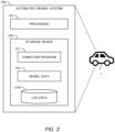
- FIG. 2 is a diagram showing an example of a hardware configuration of an automated driving system 100 according to the present embodiment.
- the automated driving system 100 has at least the function of the automated driving control unit described above.
- the automated driving system 100 may further include the sensor group 10 and the travel device 50.
- the automated driving system 100 includes one or more processors 110 (hereinafter, simply referred to as a processor 110 or processing circuitry) and one or more storage devices 120 (hereinafter, simply referred to as a storage device 120).
- processors 110 hereinafter, simply referred to as a processor 110 or processing circuitry
- storage devices 120 hereinafter, simply referred to as a storage device 120.
- the processor 110 executes a variety of processing.
- the processor 110 may be configured with a central processing unit (CPU), a graphics processing unit (GPU), an application specific integrated circuit (ASIC), a field-programmable gate array (FPGA), and the like.
- the recognition unit 20, the planning unit 30, and the control amount calculation unit 40 may be implemented by a single processor 110 or may be respectively implemented by separate processors 110.
- the storage device 120 stores a variety of information necessary for the processor 110 to execute processing.
- the storage device 120 may be configured with a read only memory (ROM), a random access memory (RAM), a hard disk drive (HDD), a solid state drive (SSD), and the like.
- the storage device 120 stores a computer program 121, model data 122, and log data LOG.
- a computer program 121 is executed by the processor 110.
- the variety of processing by the automated driving system 100 may be implemented by a cooperation of the processor 110 executing the computer program 121 and the storage device 120.
- the computer program 121 may be recorded on a non-transitory computer-readable recording medium.
- the model data 122 is data of models included in the recognition unit 20, the planning unit 30, and the control amount calculation unit 40.
- the processor 110 executes the processing related to the automated driving control, the processor 110 selects and uses a model from the model data 122 to configure the recognition unit 20, the planning unit 30, and the control amount calculation unit 40.
- the processor 110 While performing the automated driving control, the processor 110 acquires "log data LOG" related to the automated driving control. the processor 110 stores the acquired log data LOG in the storage device 120. It is expected that the stored log data LOG is used for verification of the automated driving control.
- the log data LOG collected and stored includes at least log data of the sensor detection information SEN detected by the recognition sensor 11.
- the log data LOG may include log data of the sensor detection information SEN detected by the state sensor 12 or the position sensor 13.
- the log data LOG may include log data of the control amount CON output from the automated driving control unit, log data of the recognition result information RES output from the recognition unit 20, log data of the target trajectory TRJ output from the planning unit 30, and the like.
- the processor 110 collects at least log data of the sensor detection information SEN detected by the recognition sensor 11 and stores the log data in the storage device 120 while performing the automated driving control.
- the automated driving control unit recognizes the situation around the vehicle 1 based on the sensor detection information SEN detected by the recognition sensor 11, and performs the automated driving control of the vehicle 1 based on the recognition result. Therefore, the log data of the sensor detection information SEN detected by the recognition sensor 11 is data particularly required for verification of the automated driving control.
- the sensor detection information SEN detected by the recognition sensor 11 is simply referred to as the "detection information”.
- the log data of the detection information includes image data, point cloud data, and the like. Therefore, the data amount of the log data of the detection information is likely to be large. On the other hand, the capacity of the storage device 120 for storing the log data LOG is limited. If the data amount of the log data LOG increases and the capacity of the storage device 120 is strained, there is a possibility that necessary log data will not be able to be stored. Therefore, when storing log data, it is required to efficiently use the capacity of the storage device 120.
- the recognition result information RES may include a recognition result with high reliability or a recognition result with low reliability.
- the recognition result information RES regarding recognized objects around the vehicle 1 may include a recognized object whose position, state, behavior prediction, etc. are recognized with high reliability, or may include a recognized object whose position, state, behavior prediction, etc. are recognized with low reliability.
- the automated driving control performed based on the recognition result with low reliability is likely to deviate from the intended operation of the vehicle 1. Therefore, when performing ex-post verification of the autonomous driving control, it is considered that a recognition result with low reliability is more likely to require verification than a recognition result with high reliability. That is, it is considered that the log data of the detection information related to the recognition result with low reliability is more necessary in the verification of the automated driving control.
- the automated driving system 100 makes it possible to efficiently use the capacity of the storage device 120.
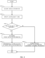
- FIG. 3 is a flowchart showing an example of a process (storing process) executed by the processor 110 with respect to storing the log data of the detection information.
- the processing according to the flowchart shown in FIG. 3 is repeatedly executed at a predetermined processing cycle while performing the automated driving control, for example.
- the processor 110 acquires various information. At least the processor 110 acquires the detection information and the recognition result information RES.
- the recognition result information RES is generated to include reliability information for each recognition result.
- the reliability is the confidence level of the machine learning model for each recognition result.
- the reliability is the probability of each recognition result in the statistical model.
- the processor 110 refers to the recognition result information RES and specifies an area where the reliability of the recognition result is low (hereinafter, referred to as a "low reliability area") around the vehicle 1. For example, the processor 110 specifies an area including the recognition result whose reliability is equal to or less than a predetermined threshold value as the low reliability area.
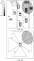
- FIG. 4A is a diagram showing an example of a low reliability area 2.
- the processor 110 specifies the low reliability area 2 so as to include the recognized objects OB7, OB8, and OB9.
- the shape and range of the low reliability area 2 may be suitably determined according to the environment to which the present embodiment is applied.
- the low reliability area 2 may be constituted by two or more areas.
- the processor 110 may specify three regions for each of the recognition objects OB7, OB8, and OB9 as the low reliability area 2.
- the processor 110 may not specify the low reliability area 2.
- the processor 110 may specify an area including a point where the reliability of the risk value is low as the low reliability area, for example.
- step S160 the processor 110 stores the log data of the detection information according to the normal procedure (step S160).
- the normal procedure may be any suitable one known in the art. After step S160, the current process ends.
- step S120 When the low reliability area 2 is specified in step S120 (step S130; Yes), the process proceeds to step S140.
- the processor 110 determines information related to the low reliability area 2 (hereinafter, referred to as "target detection information") among the detection information.
- the target detection information is, for example, image data captured by a camera that includes the low reliability area 2 in an imaging range, point cloud data detected by a LIDAR that includes the low reliability area 2 in a detection range, point cloud data detected in the low reliability area 2, information of an object detected by a radar that includes the low reliability area 2 in a detection range, information of an object detected in the low reliability area 2, and the like.
- FIG. 4B is a diagram for explaining an example of the target detection information.
- four detection ranges D1, D2, D3, and D4 of the recognition sensor 11 are shown. That is, in the example shown in FIG. 4B , the detection information of the recognition sensor 11 corresponding to each of the four detection ranges D1, D2, D3, and D4 is acquired.
- the detection ranges D1 and D4 include the low reliability area 2.
- the detection ranges D2 and D3 do not include the low reliability area 2. Therefore, in this case, the processor 110 determines, as the target detection information, the detection information of the recognition sensor 11 with the detection range D 1 and the detection information of the recognition sensor 11 with the detection range D4 among the acquired detection information.
- step S150 the processor 110 preferentially store the log data of the target detection information. That is, when the low reliability area 2 is specified, the target detection information related to the low reliability area 2 is preferentially treated in storing the log data of the detection information.
- step S150 the current process ends.
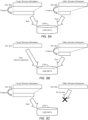
- FIGS. 5A, 5 B, and 5 C are conceptual diagrams showing examples of preferential storage of the log data of the target detection information.
- each of FIGS. 5A, 5 B, and 5 C show a case where the processor 110 stores compressed detection information as log data.
- the processor 110 stores the log data by setting a compression rate of the target detection information lower than that of other detection information.
- the higher the compression rate the more the data amount can be reduced, but the more information is lost. Therefore, by setting the compression rate of the target detection information lower than that of other detection information, it is possible to store the log data of the target detection information in a richer manner with emphasis on preserving information. On the other hand, it is possible to store the log data of other detection information with emphasis on reducing the data amount.
- the processor 110 may be configured to apply lossless compression to the target detection information and lossy compression with a high compression rate to other detection information. In this way, in the example shown in FIG. 5A , preferential storage of the log data of the target detection information is realized.
- the processor 110 stores the log data of the target detection information without compressing. This can also be seen as setting the compression rate of the target detection information to 0%. In this sense, the example shown in FIG. 5B can be considered as a part of the example shown in FIG. 5A . Therefore, in the example shown in FIG. 5B , preferential storage of the log data of the target detection information is realized as in the example shown in FIG. 5A .
- the processor 110 stores only the log data of the target detection information. That is, in the example shown in FIG. 5C , the processor 110 does not store the log data of other detection information. In this way, in the example shown in FIG. 5C , preferential storage of the log data of the target detection information is realized.
- the processor 110 may be configured to switch the method of storing the log data of the target detection information depending on the free capacity of the storage device 120. For example, the processor 110 may be configured to store the log data of the detection information as shown in FIG. 5B when the free capacity is sufficient, store the log data of the detection information as shown in FIG. 5A when the free capacity is less than a first threshold value, and store the log data of the detection information as shown in FIG. 5C when the free capacity is further less than a second threshold value.
- the processor 110 executes processing related to the storage of the log data of the detection information.
- a log data storage method according to the present embodiment is realized by the processor 110 executing the processing in this way.
- a log data storage program according to the present embodiment is realized by the computer program 121 that causes the processor 110 to execute the processing in this way.
- the log data of the target detection information is preferentially stored.
- the target detection information is the detection information related to the low reliability area 2 where the reliability of the recognition result is low, and is more necessary in the verification of the automated driving control. Therefore, according to the present embodiment, from the viewpoint of the high necessity in the verification of the automated driving control, the capacity of the storage device 120 can be efficiently used.
- the automated driving system 100 according to the present embodiment may adopt the following modified embodiment.
- Each recognition result included in the recognition result information RES may be involved in the calculation of the control amount of the automated driving control or may not be involved in the calculation of the control amount of the automated driving control.
- the planning unit 30 when the planning unit 30 generates the travel plan or the target trajectory TRJ based on the recognition result information RES, a part of the recognition result information RES may not be involved in the generation of the travel plan or the target trajectory TRJ.
- a recognition result involved in the calculation of the control amount of the automated driving control (hereinafter, referred to as a "specific recognition result”) is more likely to require verification than a recognition result not involved in the calculation of the control amount of the automated driving control. That is, it is considered that the log data of the detection information related to the specific recognition result is more necessary in the verification of the automated driving control.
- the processor 110 may be configured to, when storing the log data of the target detection information, store the log data of information related to the specific recognition result among the target detection information with higher priority. For example, the processor 110 may store the log data by setting the compression rate of the information related to the specific recognition result lower than that of other target detection information.
- FIGS. 6A and 6B are diagrams for explaining information related to the specific recognition result.
- FIG. 6A shows the target trajectory TRJ generated by the recognition unit 20.
- the target trajectory TRJ is generated so as to avoid the recognized object OB1 which is a parked vehicle parked on the roadside. That is, the recognized object OB1 is a specific recognition result.
- FIG. 6B similar to the case shown in FIG. 4B , four detection ranges D1, D2, D3, and D4 of the recognition sensor 11 and the low reliability area 2 are shown. Further, FIG. 6B shows the recognized object OB1 which is the specific recognition result. In FIG. 6B , similar to the case shown in FIG.
- the processor 110 determines, as the target detection information, the detection information of the recognition sensor 11 with the detection range D 1 and the detection information of the recognition sensor 11 with the detection range D4 among the acquired detection information. Further, the detection range D1 includes the recognized object OB1 which is the specific recognition result. That is, the detection information of the recognition sensor 11 with the detection range D1 is information related to the specific recognition result. Therefore, in this case, the processor 110 stores the detection information of the recognition sensor 11 with the detection range D1 with higher priority when storing the log data of the target detection information.
- the capacity of the storage device 120 can be used more efficiently from the viewpoint of the high necessity in the verification of the automated driving control.
- the processor 110 may be configured to generate reproduction data for reproducing the detection information in a pseudo manner. And the processor 110 may be configured to store the generated reproduction data as the log data.
- the processor 110 when the detection information is image data, the processor 110 generates, as reproduction data, information capable of generating an image that reproduces an object captured in original image data in a pseudo manner.
- the reproduction data may be information on a position, a state (e.g., blur, darkness, and the like), a shape, etc. of an object captured in original image data.
- the processor 110 may be configured to generate the reproduction data using the parameters in the approximate space of the image data.
- the detection information is point cloud data
- the processor 110 when the detection information is point cloud data, the processor 110 generates, as reproduction data, information capable of generating a point cloud that reproduces original point cloud data in a pseudo manner.
- the reproduction data may be information on the intensity of the reflected light detected by a LIDAR when the original point cloud data is detected.
- the reproduction data is information for reproducing the detection information in a pseudo manner
- the data amount is smaller than that of the original detection information.
- the detection information reproduced in a pseudo manner by the reproduction data is expected to output the same recognition result information RES as the original detection information. Therefore, by employing such a modified embodiment, it is possible to reduce the data amount of the log data while ensuring the verification of the automated driving control.
- the data amount of the reproduction data varies depending on how faithfully original information is reproduced. That is, the more faithful the reproduction, the less information is lost, but the larger the data amount becomes.
- the processor 110 may be configured to generate the reproduction data that reproduces original information more faithfully with respect to the target detection information than with respect to other detection information. This configuration also makes it possible to realized preferential storage of the log data of the target detection information. Furthermore, the processor 110 may be configured to store the compressed reproduction data as the log data. In this case, the processor 110 may be configured to realize the preferential storage of the log data of the target detection information as described with reference to FIGS. 5A, 5B, and 5C .
Landscapes
- Engineering & Computer Science (AREA)
- Physics & Mathematics (AREA)
- General Physics & Mathematics (AREA)
- General Engineering & Computer Science (AREA)
- Theoretical Computer Science (AREA)
- Computer Hardware Design (AREA)
- Quality & Reliability (AREA)
- Data Mining & Analysis (AREA)
- Databases & Information Systems (AREA)
- Mathematical Physics (AREA)
- Software Systems (AREA)
- Traffic Control Systems (AREA)
Abstract
An automated driving system (100) one or more processors (110) configured to recognize a situation around the vehicle (1) from detection information detected by a recognition sensor (11) and perform automated driving control based on a recognition result. The automated driving system (100) execute a storing process of storing log data of the detection information in one or more storage devices (120) while performing the automated driving control. In the storing process, the automated driving system (100) specify a low reliability area (2) around the vehicle (1) where a reliability of the recognition result is low. When the low reliability area (2) is specified, the automated driving system (100) preferentially store the log data of target detection information that is the detection information related to the low reliability area (2).
Description
- The present disclosure claims priority to the contents of which application are incorporated herein by reference in their entirety.
- The present disclosure relates to an automated driving system installed on a vehicle.
- A technique of performing automated driving control of a vehicle by using a machine learning model is known.
Patent Literature 1 discloses a method for collecting training data that can be used for training of a machine learning model. In addition, the followingPatent Literatures 2 and 3 are documents showing the technical level of the present technical field. -
-
Patent Literature 1;WO 2019116423 A1 - Patent Literature 2:
JP 2021174413 A - Patent Literature 3:
JP 2022023956 A - As a method for ex-post facto assessment of automated driving control of a vehicle, it is containable to store log data related to the automated driving control in an in-vehicle storage device. However, since the capacity of the storage device installed in the vehicle is limited, if the capacity of the storage device is strained, there is a possibility that necessary log data will not be able to be stored. Among log data related to the automated driving control, the log data of detection information by a recognition sensor that detects information around a vehicle is particularly required for the verification of the automated driving control, but the data amount thereof is likely to be large.
- An object of the present disclosure is, in the view of the above problems, to provide a technique capable of efficiently using the capacity of a storage device.
- One aspect of the present disclosure is directed to an automated driving system installed in a vehicle.
- The automated driving system comprises:
- a recognition sensor detecting information around the vehicle;
- one or more processors configured to recognize a situation around the vehicle from detection information detected by the recognition sensor and perform automated driving control based on a recognition result; and
- one or more storage devices.
- The one or more processors are further configured to execute a storing process of storing log data of the detection information in the one or more storage devices while performing the automated driving control.
- In the storing process, the one or more processors are configured to:
- specify a low reliability area around the vehicle where a reliability of the recognition result is low; and
- when the low reliability area is specified, preferentially store the log data of target detection information that is the detection information related to the low reliability area.
- According to the present disclosure, the log data of the target detection information that is the detection information related to the low reliability area is preferentially stored. The low reliability area is an area around the vehicle where the reliability of the recognition result is low. This allows the capacity of the storage device to be used efficiently from the viewpoint of the high necessity in the verification of the automated driving control.
-
-
FIG. 1 is a diagram showing an example of a configuration related to automated driving control of a vehicle according to the present embodiment; -
FIG. 2 is a diagram showing an example of a hardware configuration of the automated driving system according to the present embodiment; -
FIG. 3 is a flowchart showing a process executed by a processor according to the present embodiment; -
FIG. 4A is a diagram for explaining a low reliability area; -
FIG. 4B is a diagram for explaining target detection information; -
FIG. 5A is a diagram for explaining preferential storage of log data of the target detection information; -
FIG. 5B is a diagram for explaining preferential storage of the log data of the target detection information; -
FIG. 5C is a diagram for explaining preferential storage of the log data of the target detection information; and -
FIG. 6 is a diagram for explaining information related to a specific recognition result. - The present embodiment relates to an automated driving system that is installed on a vehicle and performs automated driving control of the vehicle.
FIG. 1 is a diagram showing an example of a configuration related to automated driving control of avehicle 1 by an automated driving system according to the present embodiment. The automated driving is to automatically perform at least one of steering, acceleration, and deceleration of thevehicle 1 without depending on a driving operation performed by an operator. The automated driving control is a concept including not only complete automated driving control but also risk avoidance control, lane keep assist control, and the like. The operator may be a driver on board thevehicle 1 or may be a remote operator who remotely operates thevehicle 1. - The
vehicle 1 includes asensor group 10, arecognition unit 20, aplanning unit 30, a controlamount calculation unit 40, and atravel device 50. - The
sensor group 10 includes arecognition sensor 11 detecting information around thevehicle 1. Examples of therecognition sensor 11 include a camera, a laser imaging detection and ranging (LIDAR), a radar, and the like. Thesensor group 10 may further include astate sensor 12 that detects a state of thevehicle 1, aposition sensor 13 that detects a position of thevehicle 1, and the like. Examples of thestate sensor 12 include a speed sensor, an acceleration sensor, a yaw rate sensor, a steering angle sensor, and the like. As theposition sensor 13, a global navigation satellite system (GNSS) sensor is exemplified. - Sensor detection information SEN is information detected by the
sensor group 10. For example, the sensor detection information SEN includes image data captured (taken) by the camera. Furthermore, the sensor detection information SEN may include information (e.g., relative position, relative velocity, class, and the like) regarding a specific object appearing in the image (e.g., a pedestrian, a preceding vehicle, a white line, a bicycle, a road sign, and the like). Also, for example, the sensor detection information SEN may include point cloud data detected by the LIDAR. Also, for example, the sensor detection information SEN may include information on a relative position and a relative velocity of objects detected by the radar. The sensor detection information SEN may include vehicle state information indicating the state of thevehicle 1. The sensor detection information SEN may include position information indicating the position of thevehicle 1. - The
recognition unit 20 receives the sensor detection information SEN. Therecognition unit 20 recognizes a situation around thevehicle 1 based on the sensor detection information SEN detected by therecognition sensor 11. Also, for example, therecognition unit 20 generates a space map in which the recognized object is integrated into the map information. Examples of the object include a pedestrian, another vehicle (e.g., a preceding vehicle, a parked vehicle, and the like), a white line, a road structure (e.g., a guard rail, a curb, and the like), a fallen object, a traffic light, an intersection, a sign, and the like. Furthermore, therecognition unit 20 may perform prediction of the behavior of an object around thevehicle 1. Recognition result information RES indicates a result of recognition by therecognition unit 20. - The
planning unit 30 receives the recognition result information RES from therecognition unit 20. Theplanning unit 30 generates a travel plan of thevehicle 1 based on the received recognition result information RES. Theplanning unit 30 may further receive the vehicle state information and the position information. The travel plan may be one for arriving at a destination set in advance. The travel plan may be one for avoiding a risk. The travel plan provides driving decisions such as, for example, maintaining a current travel lane, making a lane change, overtaking, making a right or left turn, steering, accelerating, decelerating, stopping, and the like. Further, theplanning unit 30 generates a target trajectory TRJ required for thevehicle 1 to travel in accordance with the travel plan. The target trajectory TRJ includes a target position and a target velocity. - The control
amount calculation unit 40 receives the target trajectory TRJ from theplanning unit 30. The controlamount calculation unit 40 calculates a control amount CON required for thevehicle 1 to follow the target trajectory TRJ. It can be also said that the control amount CON is a control amount required for reducing a deviation of thevehicle 1 from the target trajectory TRJ. The control amount CON includes at least one of a steering control amount, a driving control amount, and a braking control amount. Examples of the steering control amount include a target steering angle, a target steering torque, a target motor angle, a target motor drive current, and the like. Examples of the driving control amount include a target driving force, a target engine torque, and the like. Examples of the braking control amount include a target braking force, a target braking torque, and the like. - The
travel device 50 includes asteering device 51, a drivingdevice 52, and abraking device 53. Thesteering device 51 steers wheels of thevehicle 1. The drivingdevice 52 is a power source that generates a driving force. Examples of the drivingdevice 52 include an engine, an electric motor, an in-wheel motor, and the like. Thebraking device 53 generates a braking force. Thetravel device 50 receives the control amount CON from the controlamount calculation unit 40. Thetravel device 50 operates thesteering device 51, the drivingdevice 52, and thebraking device 53 in accordance with the steering control amount, the driving control amount, and the braking control amount, respectively. Thus, thevehicle 1 travels so as to follow the target trajectory TRJ. - The
recognition unit 20 includes at least one of a rule-based model and a machine learning model. The rule-based model performs the recognition process based on a predetermined rule group. Examples of the machine learning model include a neural network (NN), a support vector machine (SVM), a regression model, a decision tree model, and the like. The NN may be a convolutional neural network (CNN), a recurrent neural network (RNN), or a combination of CNN and RNN. The type of each layer, the number of layers, and the number of nodes in the NN are arbitrary. The machine learning model is generated in advance through machine learning. Therecognition unit 20 performs the recognition process by inputting the sensor detection information SEN into the model. The recognition result information RES is output from the model or generated based on the output from the model. - Similarly, the
planning unit 30 also includes at least one of a rule-based model and a machine learning model. Theplanning unit 30 performs the planning process by inputting the recognition result information RES into the model. The target trajectory TRJ is output from the model or generated based on the output from the model. - Similarly, the control
amount calculation unit 40 also includes at least one of a rule-based model and a machine learning model. The controlamount calculation unit 40 performs the control amount calculation process by inputting the target trajectory TRJ into the model. The control amount CON is output from the model or generated based on the output from the model. - Two or more of the
recognition unit 20, theplanning unit 30, and the controlamount calculation unit 40 may have an integrated architecture. All of therecognition unit 20, theplanning unit 30, and the controlamount calculation unit 40 may have an integrated architecture (End-to-End architecture). For example, therecognition unit 20 and theplanning unit 30 may have an integrated architecture that generates and outputs the target trajectory TRJ directly from the sensor detection information SEN. Even in the case of the integrated architecture, intermediate products such as the recognition result information RES and the target trajectory TRJ may be output. For example, in a case where therecognition unit 20 and theplanning unit 30 have an integrated architecture based on a NN, the recognition result information RES may be an output from an intermediate layer of the NN. - The
recognition unit 20, theplanning unit 30, and the controlamount calculation unit 40 constitute an "automated driving control unit" that controls the automated driving of thevehicle 1. -
FIG. 2 is a diagram showing an example of a hardware configuration of anautomated driving system 100 according to the present embodiment. Theautomated driving system 100 has at least the function of the automated driving control unit described above. Theautomated driving system 100 may further include thesensor group 10 and thetravel device 50. - The
automated driving system 100 includes one or more processors 110 (hereinafter, simply referred to as aprocessor 110 or processing circuitry) and one or more storage devices 120 (hereinafter, simply referred to as a storage device 120). - The
processor 110 executes a variety of processing. Theprocessor 110 may be configured with a central processing unit (CPU), a graphics processing unit (GPU), an application specific integrated circuit (ASIC), a field-programmable gate array (FPGA), and the like. Therecognition unit 20, theplanning unit 30, and the controlamount calculation unit 40 may be implemented by asingle processor 110 or may be respectively implemented byseparate processors 110. Thestorage device 120 stores a variety of information necessary for theprocessor 110 to execute processing. Thestorage device 120 may be configured with a read only memory (ROM), a random access memory (RAM), a hard disk drive (HDD), a solid state drive (SSD), and the like. - The
storage device 120 stores acomputer program 121,model data 122, and log data LOG. - A
computer program 121 is executed by theprocessor 110. The variety of processing by theautomated driving system 100 may be implemented by a cooperation of theprocessor 110 executing thecomputer program 121 and thestorage device 120. Thecomputer program 121 may be recorded on a non-transitory computer-readable recording medium. - The
model data 122 is data of models included in therecognition unit 20, theplanning unit 30, and the controlamount calculation unit 40. When theprocessor 110 executes the processing related to the automated driving control, theprocessor 110 selects and uses a model from themodel data 122 to configure therecognition unit 20, theplanning unit 30, and the controlamount calculation unit 40. - While performing the automated driving control, the
processor 110 acquires "log data LOG" related to the automated driving control. theprocessor 110 stores the acquired log data LOG in thestorage device 120. It is expected that the stored log data LOG is used for verification of the automated driving control. In the present embodiment, the log data LOG collected and stored includes at least log data of the sensor detection information SEN detected by therecognition sensor 11. The log data LOG may include log data of the sensor detection information SEN detected by thestate sensor 12 or theposition sensor 13. - In addition, the log data LOG may include log data of the control amount CON output from the automated driving control unit, log data of the recognition result information RES output from the
recognition unit 20, log data of the target trajectory TRJ output from theplanning unit 30, and the like. - As described above, in the present embodiment, the
processor 110 collects at least log data of the sensor detection information SEN detected by therecognition sensor 11 and stores the log data in thestorage device 120 while performing the automated driving control. The automated driving control unit recognizes the situation around thevehicle 1 based on the sensor detection information SEN detected by therecognition sensor 11, and performs the automated driving control of thevehicle 1 based on the recognition result. Therefore, the log data of the sensor detection information SEN detected by therecognition sensor 11 is data particularly required for verification of the automated driving control. Hereinafter, the sensor detection information SEN detected by therecognition sensor 11 is simply referred to as the "detection information". - The log data of the detection information includes image data, point cloud data, and the like. Therefore, the data amount of the log data of the detection information is likely to be large. On the other hand, the capacity of the
storage device 120 for storing the log data LOG is limited. If the data amount of the log data LOG increases and the capacity of thestorage device 120 is strained, there is a possibility that necessary log data will not be able to be stored. Therefore, when storing log data, it is required to efficiently use the capacity of thestorage device 120. - The recognition result information RES may include a recognition result with high reliability or a recognition result with low reliability. For example, the recognition result information RES regarding recognized objects around the
vehicle 1 may include a recognized object whose position, state, behavior prediction, etc. are recognized with high reliability, or may include a recognized object whose position, state, behavior prediction, etc. are recognized with low reliability. The automated driving control performed based on the recognition result with low reliability is likely to deviate from the intended operation of thevehicle 1. Therefore, when performing ex-post verification of the autonomous driving control, it is considered that a recognition result with low reliability is more likely to require verification than a recognition result with high reliability. That is, it is considered that the log data of the detection information related to the recognition result with low reliability is more necessary in the verification of the automated driving control. - From the above viewpoint, the
automated driving system 100 according to the present embodiment makes it possible to efficiently use the capacity of thestorage device 120. -
FIG. 3 is a flowchart showing an example of a process (storing process) executed by theprocessor 110 with respect to storing the log data of the detection information. The processing according to the flowchart shown inFIG. 3 is repeatedly executed at a predetermined processing cycle while performing the automated driving control, for example. - First, in step S110, the
processor 110 acquires various information. At least theprocessor 110 acquires the detection information and the recognition result information RES. In the present embodiment, the recognition result information RES is generated to include reliability information for each recognition result. For example, when therecognition unit 20 is configured by a machine learning model, the reliability is the confidence level of the machine learning model for each recognition result. Also, for example, when therecognition unit 20 is configured by a rule-based model based on a statistical model, the reliability is the probability of each recognition result in the statistical model. - Next, in step S120, the
processor 110 refers to the recognition result information RES and specifies an area where the reliability of the recognition result is low (hereinafter, referred to as a "low reliability area") around thevehicle 1. For example, theprocessor 110 specifies an area including the recognition result whose reliability is equal to or less than a predetermined threshold value as the low reliability area. -
FIG. 4A is a diagram showing an example of alow reliability area 2. InFIG. 4A , multiple recognized objects OBj (j = 1, 2, ..., 9) around thevehicle 1 and the reliability level of each recognized object OBj are shown as the recognition result information RES. In the example shown inFIG. 4A , the reliability of the recognized objects OB7, OB8, and OB9 is low. Therefore, theprocessor 110 specifies thelow reliability area 2 so as to include the recognized objects OB7, OB8, and OB9. In this case, the shape and range of thelow reliability area 2 may be suitably determined according to the environment to which the present embodiment is applied. Thelow reliability area 2 may be constituted by two or more areas. For example, in the example shown inFIG. 4A , theprocessor 110 may specify three regions for each of the recognition objects OB7, OB8, and OB9 as thelow reliability area 2. - When there is no recognition result with low reliability, the
processor 110 may not specify thelow reliability area 2. In addition, when a risk map is given as the recognition result information RES, theprocessor 110 may specify an area including a point where the reliability of the risk value is low as the low reliability area, for example. - Refer to
FIG. 3 again. When thelow reliability area 2 is not specified in step S120 (step S130; No), theprocessor 110 stores the log data of the detection information according to the normal procedure (step S160). The normal procedure may be any suitable one known in the art. After step S160, the current process ends. - When the
low reliability area 2 is specified in step S120 (step S130; Yes), the process proceeds to step S140. - In step S140, the
processor 110 determines information related to the low reliability area 2 (hereinafter, referred to as "target detection information") among the detection information. The target detection information is, for example, image data captured by a camera that includes thelow reliability area 2 in an imaging range, point cloud data detected by a LIDAR that includes thelow reliability area 2 in a detection range, point cloud data detected in thelow reliability area 2, information of an object detected by a radar that includes thelow reliability area 2 in a detection range, information of an object detected in thelow reliability area 2, and the like. -
FIG. 4B is a diagram for explaining an example of the target detection information. InFIG. 4B , four detection ranges D1, D2, D3, and D4 of therecognition sensor 11 are shown. That is, in the example shown inFIG. 4B , the detection information of therecognition sensor 11 corresponding to each of the four detection ranges D1, D2, D3, and D4 is acquired. As shown inFIG. 4B , the detection ranges D1 and D4 include thelow reliability area 2. On the other hand, the detection ranges D2 and D3 do not include thelow reliability area 2. Therefore, in this case, theprocessor 110 determines, as the target detection information, the detection information of therecognition sensor 11 with thedetection range D 1 and the detection information of therecognition sensor 11 with the detection range D4 among the acquired detection information. - Refer to
FIG. 3 again. After step S140, the process proceeds to step S150. In step S150, theprocessor 110 preferentially store the log data of the target detection information. That is, when thelow reliability area 2 is specified, the target detection information related to thelow reliability area 2 is preferentially treated in storing the log data of the detection information. After step S150, the current process ends. -
FIGS. 5A, 5 B, and 5 C are conceptual diagrams showing examples of preferential storage of the log data of the target detection information. In particular, each ofFIGS. 5A, 5 B, and 5 C show a case where theprocessor 110 stores compressed detection information as log data. - In the example shown in
FIG. 5A , theprocessor 110 stores the log data by setting a compression rate of the target detection information lower than that of other detection information. The higher the compression rate, the more the data amount can be reduced, but the more information is lost. Therefore, by setting the compression rate of the target detection information lower than that of other detection information, it is possible to store the log data of the target detection information in a richer manner with emphasis on preserving information. On the other hand, it is possible to store the log data of other detection information with emphasis on reducing the data amount. In particular, theprocessor 110 may be configured to apply lossless compression to the target detection information and lossy compression with a high compression rate to other detection information. In this way, in the example shown inFIG. 5A , preferential storage of the log data of the target detection information is realized. - In the example shown in
FIG. 5B , theprocessor 110 stores the log data of the target detection information without compressing. This can also be seen as setting the compression rate of the target detection information to 0%. In this sense, the example shown inFIG. 5B can be considered as a part of the example shown inFIG. 5A . Therefore, in the example shown inFIG. 5B , preferential storage of the log data of the target detection information is realized as in the example shown inFIG. 5A . - In the example shown in
FIG. 5C , theprocessor 110 stores only the log data of the target detection information. That is, in the example shown inFIG. 5C , theprocessor 110 does not store the log data of other detection information. In this way, in the example shown inFIG. 5C , preferential storage of the log data of the target detection information is realized. - The
processor 110 may be configured to switch the method of storing the log data of the target detection information depending on the free capacity of thestorage device 120. For example, theprocessor 110 may be configured to store the log data of the detection information as shown inFIG. 5B when the free capacity is sufficient, store the log data of the detection information as shown inFIG. 5A when the free capacity is less than a first threshold value, and store the log data of the detection information as shown inFIG. 5C when the free capacity is further less than a second threshold value. - As described above, in the
automated driving system 100 according to the present embodiment, theprocessor 110 executes processing related to the storage of the log data of the detection information. And a log data storage method according to the present embodiment is realized by theprocessor 110 executing the processing in this way. And a log data storage program according to the present embodiment is realized by thecomputer program 121 that causes theprocessor 110 to execute the processing in this way. - As described above, according to the present embodiment, the log data of the target detection information is preferentially stored. The target detection information is the detection information related to the
low reliability area 2 where the reliability of the recognition result is low, and is more necessary in the verification of the automated driving control. Therefore, according to the present embodiment, from the viewpoint of the high necessity in the verification of the automated driving control, the capacity of thestorage device 120 can be efficiently used. - The
automated driving system 100 according to the present embodiment may adopt the following modified embodiment. - Each recognition result included in the recognition result information RES may be involved in the calculation of the control amount of the automated driving control or may not be involved in the calculation of the control amount of the automated driving control. For example, when the
planning unit 30 generates the travel plan or the target trajectory TRJ based on the recognition result information RES, a part of the recognition result information RES may not be involved in the generation of the travel plan or the target trajectory TRJ. When performing ex-post verification of the automated driving control, it is considered that a recognition result involved in the calculation of the control amount of the automated driving control (hereinafter, referred to as a "specific recognition result") is more likely to require verification than a recognition result not involved in the calculation of the control amount of the automated driving control. That is, it is considered that the log data of the detection information related to the specific recognition result is more necessary in the verification of the automated driving control. - Therefore, the
processor 110 may be configured to, when storing the log data of the target detection information, store the log data of information related to the specific recognition result among the target detection information with higher priority. For example, theprocessor 110 may store the log data by setting the compression rate of the information related to the specific recognition result lower than that of other target detection information. -
FIGS. 6A and 6B are diagrams for explaining information related to the specific recognition result.FIG. 6A shows the target trajectory TRJ generated by therecognition unit 20. InFIG. 6A , the target trajectory TRJ is generated so as to avoid the recognized object OB1 which is a parked vehicle parked on the roadside. That is, the recognized object OB1 is a specific recognition result. InFIG. 6B , similar to the case shown inFIG. 4B , four detection ranges D1, D2, D3, and D4 of therecognition sensor 11 and thelow reliability area 2 are shown. Further,FIG. 6B shows the recognized object OB1 which is the specific recognition result. InFIG. 6B , similar to the case shown inFIG. 4B , theprocessor 110 determines, as the target detection information, the detection information of therecognition sensor 11 with thedetection range D 1 and the detection information of therecognition sensor 11 with the detection range D4 among the acquired detection information. Further, the detection range D1 includes the recognized object OB1 which is the specific recognition result. That is, the detection information of therecognition sensor 11 with the detection range D1 is information related to the specific recognition result. Therefore, in this case, theprocessor 110 stores the detection information of therecognition sensor 11 with the detection range D1 with higher priority when storing the log data of the target detection information. - By adopting such a modified embodiment, the capacity of the
storage device 120 can be used more efficiently from the viewpoint of the high necessity in the verification of the automated driving control. - In the above description, the case where the
processor 110 stores the compressed detection information as the log data has been described. Further, for the purpose of reducing the data amount of the log data, theprocessor 110 may be configured to generate reproduction data for reproducing the detection information in a pseudo manner. And theprocessor 110 may be configured to store the generated reproduction data as the log data. - For example, when the detection information is image data, the
processor 110 generates, as reproduction data, information capable of generating an image that reproduces an object captured in original image data in a pseudo manner. In this case, the reproduction data may be information on a position, a state (e.g., blur, darkness, and the like), a shape, etc. of an object captured in original image data. Theprocessor 110 may be configured to generate the reproduction data using the parameters in the approximate space of the image data. For example, when the detection information is point cloud data, theprocessor 110 generates, as reproduction data, information capable of generating a point cloud that reproduces original point cloud data in a pseudo manner. In this case, the reproduction data may be information on the intensity of the reflected light detected by a LIDAR when the original point cloud data is detected. - Since the reproduction data is information for reproducing the detection information in a pseudo manner, the data amount is smaller than that of the original detection information. Further, the detection information reproduced in a pseudo manner by the reproduction data is expected to output the same recognition result information RES as the original detection information. Therefore, by employing such a modified embodiment, it is possible to reduce the data amount of the log data while ensuring the verification of the automated driving control.
- The data amount of the reproduction data varies depending on how faithfully original information is reproduced. That is, the more faithful the reproduction, the less information is lost, but the larger the data amount becomes. The
processor 110 may be configured to generate the reproduction data that reproduces original information more faithfully with respect to the target detection information than with respect to other detection information. This configuration also makes it possible to realized preferential storage of the log data of the target detection information. Furthermore, theprocessor 110 may be configured to store the compressed reproduction data as the log data. In this case, theprocessor 110 may be configured to realize the preferential storage of the log data of the target detection information as described with reference toFIGS. 5A, 5B, and 5C .
Claims (4)
- An automated driving system (100) installed on a vehicle (1) comprising:a recognition sensor (11) detecting information around the vehicle (1);one or more processors (110) configured to recognize a situation around the vehicle (1) from detection information detected by the recognition sensor (11) and perform automated driving control based on a recognition result; andone or more storage devices (120), whereinthe one or more processors (110) are further configured to execute a storing process of storing log data of the detection information in the one or more storage devices (120) while performing the automated driving control, andin the storing process, the one or more processors (110) are configured to:specify a low reliability area (2) around the vehicle (1) where a reliability of the recognition result is low; andwhen the low reliability area (2) is specified, preferentially store the log data of target detection information that is the detection information related to the low reliability area (2).
- The automated driving system (100) according to claim 1, wherein
in the storing process, the one or more processors (110) are configured to:acquire a specific recognition result that is the recognition result involved in a calculation of a control amount of the automated driving control; andstore the log data of information related to the specific recognition result among the target detection information with higher priority. - The automated driving system (100) according to claim 1 or 2, wherein
in the storing process, the one or more processors (110) are configured to:compress the detection information and store the compressed detection information as the log data; andpreferentially store the log data of the target detection information by setting a compression rate of the target detection information lower than that of other detection information. - The automated driving system (100) according to claim 1 or 2, wherein
in the storing process, the one or more processors (110) are configured to:generate reproduction data for reproducing the detection information in a pseudo manner; andstore the reproduction data as the log data.
Applications Claiming Priority (1)
| Application Number | Priority Date | Filing Date | Title |
|---|---|---|---|
| JP2023113094A JP2025010839A (en) | 2023-07-10 | 2023-07-10 | Automated driving system |
Publications (1)
| Publication Number | Publication Date |
|---|---|
| EP4492344A1 true EP4492344A1 (en) | 2025-01-15 |
Family
ID=91128443
Family Applications (1)
| Application Number | Title | Priority Date | Filing Date |
|---|---|---|---|
| EP24176021.4A Pending EP4492344A1 (en) | 2023-07-10 | 2024-05-15 | Automated driving system |
Country Status (3)
| Country | Link |
|---|---|
| US (1) | US20250022326A1 (en) |
| EP (1) | EP4492344A1 (en) |
| JP (1) | JP2025010839A (en) |
Families Citing this family (1)
| Publication number | Priority date | Publication date | Assignee | Title |
|---|---|---|---|---|
| JP2024037589A (en) * | 2022-09-07 | 2024-03-19 | 株式会社Subaru | Vehicle driving support device |
Citations (5)
| Publication number | Priority date | Publication date | Assignee | Title |
|---|---|---|---|---|
| WO2019116423A1 (en) | 2017-12-11 | 2019-06-20 | 本田技研工業株式会社 | Teacher data collection device |
| US20200043254A1 (en) * | 2017-04-11 | 2020-02-06 | Denso Corporation | Data storage device of vehicle |
| JP2021174413A (en) | 2020-04-29 | 2021-11-01 | 株式会社デンソー | Vehicle recording device and information recording method |
| US20220004777A1 (en) * | 2018-11-15 | 2022-01-06 | Sony Group Corporation | Information processing apparatus, information processing system, information processing method, and program |
| JP2022023956A (en) | 2020-12-18 | 2022-02-08 | 阿波羅智聯(北京)科技有限公司 | Abnormal data collecting method, apparatus, storage medium, and computer program used for automatic parking |
Family Cites Families (8)
| Publication number | Priority date | Publication date | Assignee | Title |
|---|---|---|---|---|
| JP5401903B2 (en) * | 2008-10-03 | 2014-01-29 | 富士通株式会社 | Failure information monitoring apparatus and failure information monitoring method |
| EP3905106A1 (en) * | 2020-04-27 | 2021-11-03 | Aptiv Technologies Limited | Method for determining a drivable area |
| JP7397759B2 (en) * | 2020-05-29 | 2023-12-13 | 日立Astemo株式会社 | electronic control unit |
| DE102020117340A1 (en) * | 2020-07-01 | 2022-01-05 | Zf Cv Systems Europe Bv | A method for capturing the surroundings with at least two independent imaging sensors for capturing the surroundings, a device for carrying out the method, a vehicle and a correspondingly designed computer program |
| US11378523B1 (en) * | 2020-12-31 | 2022-07-05 | Zoox, Inc. | Imaging device blemish detection test enclosure |
| EP4314708A4 (en) * | 2021-04-02 | 2024-12-25 | May Mobility, Inc. | Method and system for operating an autonomous agent with incomplete environmental information |
| US11790665B2 (en) * | 2021-04-29 | 2023-10-17 | Hitachi Astemo, Ltd. | Data driven dynamically reconfigured disparity map |
| EP4141838A1 (en) * | 2021-08-23 | 2023-03-01 | Zenseact AB | Validation of surrounding objects perceived by an ads-equipped vehicle |
-
2023
- 2023-07-10 JP JP2023113094A patent/JP2025010839A/en active Pending
-
2024
- 2024-05-15 EP EP24176021.4A patent/EP4492344A1/en active Pending
- 2024-07-02 US US18/761,999 patent/US20250022326A1/en active Pending
Patent Citations (6)
| Publication number | Priority date | Publication date | Assignee | Title |
|---|---|---|---|---|
| US20200043254A1 (en) * | 2017-04-11 | 2020-02-06 | Denso Corporation | Data storage device of vehicle |
| WO2019116423A1 (en) | 2017-12-11 | 2019-06-20 | 本田技研工業株式会社 | Teacher data collection device |
| US20220004777A1 (en) * | 2018-11-15 | 2022-01-06 | Sony Group Corporation | Information processing apparatus, information processing system, information processing method, and program |
| JP2021174413A (en) | 2020-04-29 | 2021-11-01 | 株式会社デンソー | Vehicle recording device and information recording method |
| US20230063930A1 (en) * | 2020-04-29 | 2023-03-02 | Denso Corporation | Vehicle recording device and information recording method |
| JP2022023956A (en) | 2020-12-18 | 2022-02-08 | 阿波羅智聯(北京)科技有限公司 | Abnormal data collecting method, apparatus, storage medium, and computer program used for automatic parking |
Also Published As
| Publication number | Publication date |
|---|---|
| US20250022326A1 (en) | 2025-01-16 |
| JP2025010839A (en) | 2025-01-23 |
Similar Documents
| Publication | Publication Date | Title |
|---|---|---|
| KR101963422B1 (en) | Collision-avoidance system for autonomous-capable vehicles | |
| US11555927B2 (en) | System and method for providing online multi-LiDAR dynamic occupancy mapping | |
| US11370420B2 (en) | Vehicle control device, vehicle control method, and storage medium | |
| CN113525413B (en) | Vehicle control device, vehicle control method, and storage medium | |
| US10909377B2 (en) | Tracking objects with multiple cues | |
| CN116209611B (en) | Method and system for using other road user's responses to self-vehicle behavior in autopilot | |
| US20200250437A1 (en) | System and method for providing context aware road-user importance estimation | |
| WO2018220829A1 (en) | Policy generation device and vehicle | |
| EP4492344A1 (en) | Automated driving system | |
| JP2022175160A (en) | Other vehicle behavior prediction device and behavior prediction model learning device | |
| US12485907B2 (en) | Control system | |
| US20250018973A1 (en) | Automated driving system | |
| EP4491485A1 (en) | Autonomous driving system and control method | |
| EP4484244A1 (en) | Control apparatus, control method, and control program | |
| US20250022325A1 (en) | Autonomous driving system | |
| EP4491484A1 (en) | Log management system and log management method | |
| US20250005977A1 (en) | Autonomous driving vehicle | |
| EP4485400A1 (en) | Automated driving system | |
| EP4485401A1 (en) | Autonomous driving vehicle | |
| US12555422B2 (en) | Autonomous driving system | |
| EP4481637A1 (en) | Update verification method, update verification system, and update verification program | |
| WO2025225163A1 (en) | Vehicle control apparatus and on-vehicle program | |
| WO2025225369A1 (en) | Vehicle control device and on-vehicle program |
Legal Events
| Date | Code | Title | Description |
|---|---|---|---|
| PUAI | Public reference made under article 153(3) epc to a published international application that has entered the european phase |
Free format text: ORIGINAL CODE: 0009012 |
|
| STAA | Information on the status of an ep patent application or granted ep patent |
Free format text: STATUS: REQUEST FOR EXAMINATION WAS MADE |
|
| 17P | Request for examination filed |
Effective date: 20240515 |
|
| AK | Designated contracting states |
Kind code of ref document: A1 Designated state(s): AL AT BE BG CH CY CZ DE DK EE ES FI FR GB GR HR HU IE IS IT LI LT LU LV MC ME MK MT NL NO PL PT RO RS SE SI SK SM TR |