EP4492263A1 - Calculation device and calculation method - Google Patents
Calculation device and calculation method Download PDFInfo
- Publication number
- EP4492263A1 EP4492263A1 EP23766458.6A EP23766458A EP4492263A1 EP 4492263 A1 EP4492263 A1 EP 4492263A1 EP 23766458 A EP23766458 A EP 23766458A EP 4492263 A1 EP4492263 A1 EP 4492263A1
- Authority
- EP
- European Patent Office
- Prior art keywords
- data
- convolution operation
- divided data
- adjacent
- processing elements
- Prior art date
- Legal status (The legal status is an assumption and is not a legal conclusion. Google has not performed a legal analysis and makes no representation as to the accuracy of the status listed.)
- Pending
Links
Images




Classifications
-
- G—PHYSICS
- G06—COMPUTING OR CALCULATING; COUNTING
- G06F—ELECTRIC DIGITAL DATA PROCESSING
- G06F17/00—Digital computing or data processing equipment or methods, specially adapted for specific functions
- G06F17/10—Complex mathematical operations
- G06F17/15—Correlation function computation including computation of convolution operations
-
- G—PHYSICS
- G06—COMPUTING OR CALCULATING; COUNTING
- G06F—ELECTRIC DIGITAL DATA PROCESSING
- G06F15/00—Digital computers in general; Data processing equipment in general
- G06F15/76—Architectures of general purpose stored program computers
- G06F15/80—Architectures of general purpose stored program computers comprising an array of processing units with common control, e.g. single instruction multiple data processors
-
- G—PHYSICS
- G06—COMPUTING OR CALCULATING; COUNTING
- G06F—ELECTRIC DIGITAL DATA PROCESSING
- G06F17/00—Digital computing or data processing equipment or methods, specially adapted for specific functions
- G06F17/10—Complex mathematical operations
-
- G—PHYSICS
- G06—COMPUTING OR CALCULATING; COUNTING
- G06F—ELECTRIC DIGITAL DATA PROCESSING
- G06F17/00—Digital computing or data processing equipment or methods, specially adapted for specific functions
- G06F17/10—Complex mathematical operations
- G06F17/15—Correlation function computation including computation of convolution operations
- G06F17/153—Multidimensional correlation or convolution
-
- G—PHYSICS
- G06—COMPUTING OR CALCULATING; COUNTING
- G06N—COMPUTING ARRANGEMENTS BASED ON SPECIFIC COMPUTATIONAL MODELS
- G06N3/00—Computing arrangements based on biological models
- G06N3/02—Neural networks
- G06N3/04—Architecture, e.g. interconnection topology
- G06N3/0464—Convolutional networks [CNN, ConvNet]
-
- G—PHYSICS
- G06—COMPUTING OR CALCULATING; COUNTING
- G06N—COMPUTING ARRANGEMENTS BASED ON SPECIFIC COMPUTATIONAL MODELS
- G06N3/00—Computing arrangements based on biological models
- G06N3/02—Neural networks
- G06N3/06—Physical realisation, i.e. hardware implementation of neural networks, neurons or parts of neurons
- G06N3/063—Physical realisation, i.e. hardware implementation of neural networks, neurons or parts of neurons using electronic means
Definitions
- the CNN requires an overlap region where the perimeters of adjacent two tiles overlap with one another.
- the overlap region indicates data which is necessary for execution of convolution operation using a sliding filter (sliding window).
- the overlap region is also referred to as overlap data. Therefore, when the CNN is executed by an arithmetic device in which multiple arithmetic units are arranged in a two-dimensional array, each arithmetic unit and adjacent arithmetic unit, which perform layer-by-layer arithmetic operations, are required to perform arithmetic operations on the overlap data.
- Activation 0, Activation 1, and Activation 2 each corresponds to arithmetic operation executed by one layer. That is, when the arithmetic operation executed by the first layer is Activation 0, then Activation 1 is the arithmetic operation executed by inputting an arithmetic operation result of the Activation 0 into the next layer, and Activation 2 is the arithmetic operation executed by inputting an arithmetic operation result of the Activation 1 into the next layer. In FIG. 9 , Activation 2 is the arithmetic operation executed by the last layer.
- a calculation method executed by a calculation device includes multiple processing elements, each of which performing an arithmetic operation on each of multiple divided data elements.
- the multiple divided data elements are generated by dividing input data input to the calculation device.
- Each of the multiple processing elements continuously performs a convolution operation on the corresponding divided data element in each of multiple layers.
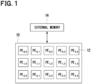
- FIG. 1 shows a schematic configuration of a calculation device 10 according to the present embodiment.
- the calculation device 10 of the present embodiment includes multiple processing elements 12 (hereinafter referred to as PEs), which are provided by arithmetic units.
- the calculation device 10 performs arithmetic operations based on a convolutional neural network (CNN).
- Each PE 12 divides the input data, which is multi-dimensional array data, into multiple elements of division data (hereinafter referred to as "tiles").
- the convolution operation is performed for each input tile by parallel distributed processing.
- the number of tiles into which the input data is divided is the same as the number of PEs 12 included in the calculation device 10.
- the multi-dimensional array data is also referred to as tensor data. In the present embodiment, image data will be described as an example of the tensor data.
- Multi-dimensional array data is not limited to 3-dimensional array data, such as image data.
- the multi-dimensional array data may be any n-dimensional array data.
- the calculation device 10 includes 15 PEs 12 arranged in three rows and five columns. The number and arrangement of PEs 12 is not limited to the example shown in FIG. 1 .
- the PE 12 continuously performs layer-by-layer convolution operations to the tile (hereinafter referred to as "Fuse execution").
- Fuse execution the intermediate data, which is the intermediate result of the layer-by-layer convolution operation performed to tile, is not written to the external memory 14. This configuration can reduce the amount of data transmitted to the external memory 14, and thus can reduce the execution duration of CNN operation.
- the conventional Fuse execution determines a division data region to be processed in the first layer by assuming, in advance, an overlap data region that is needed in the last layer. Therefore, in the conventional Fuse execution, the volume of overlap data increases with an increase of the number of layers, thereby increasing the processing load of arithmetic operation for the overlap data.
- the first layer is referred to as the start layer and the last layer is referred to as end layer.
- the ALU 20 is an arithmetic unit that performs layer-by-layer convolution operation on the input tile.
- the ALU 20 in the present embodiment performs Fuse execution on the input tile.
- the sender 24 sends data to the adjacent PEs 12.
- the receiver 26 receives data from the adjacent PEs 12.
- the PE 12 sends or receives overlap data to or from the adjacent PE 12 via the sender 24 and the receiver 26.
- commands each of which indicates a relationship between the overlap data to be sent and the destination PE 12 to which the overlap data is to be sent, are registered.
- the sender 24 sends the overlap data to the adjacent PEs 12 according to the command registered in the queue 28.
- the data input to the start layer of the multiple layers is multiple tiles, which are generated by dividing the input data into multiple elements.
- the data units that configure the tile are also referred to as neuron data.
- the neuron data that configures the tile, which is input to the PE 12, is referred to as input neuron data.
- the neuron data that configures the result of convolution operation performed by the PE 12 is referred to as output neuron data.
- the tile input to the PE 12 in the present embodiment includes overlap neuron data between the adjacent PE 12 so that only the convolution operation by the start layer can be executed.
- overlap data is received from the adjacent PE 12 in the second and subsequent layer operation.
- the tile that is the target of operation in the start layer cannot receive overlap data from the adjacent PE 12.
- the tile that is the target of operation in the start layer is required to include the overlap data in advance.
- the tiles generated from the input data are assigned to the PEs 12 so that the neuron data does not overlap in the second and subsequent layers of convolution operation, but the tile to be processed in the start layer includes the neuron data that overlaps with the adjacent PE 12.
- the ALU 20 of each PE 12 performs layer-by-layer operation on the tile, which include multiple pieces of input neuron data 30, and stores the operation result, which corresponds to the output neuron data 32, in the internal RAM 22.
- regions indicated by "0, 0" to "4, 5" indicate respective locations of multiple pieces of input neuron data 30 that are included in the tile.
- the input neuron data30 is stored in the internal RAM22, and then output to the ALU 20, where layer-by-layer convolution operation is performed.
- the output neuron data 32 is then output from the ALU 20 as a result of the convolution operation on the input neuron data 30, and the output neuron data 32 is stored in the internal RAM 22.
- the output neuron data 32 shown in white background in FIG. 2 , is the result of the convolution operation of the input neuron data 30.
- the PE 12 sends the output neuron data 32, which is the overlap data, to the adjacent PE 12 every time the convolution operation corresponding to the layer is completed.
- the overlap data corresponds to the periphery data of output neuron data 32 obtained by calculation executed as described above.
- the overlap data includes "1, 1", “1, 2", “1, 3", “1, 4", "2, 1", “2, 4", "3, 1", "3, 2", “3, 3", and "3, 4".
- the overlap data is sent to the adjacent PE 12 based on the registered relationship in the queue 28.
- the output neuron data 32 in "3, 4" is sent to the adjacent PE 12 on lower right side (SE: South East).
- the output neuron data 32 in "3, 1” is sent to the adjacent PE 12 on lower left side (SW: South West).
- the output neuron data 32 in "1, 4", "2, 4", and "3, 4" are sent to the adjacent PEs 12 on the right side (E).
- the output neuron data 32 in "3, 1", “3, 2", “3, 3", and "3, 4" are sent to the adjacent PEs 12 on the lower side (S).
- the output neuron data 32 in “1, 1”, “2, 1”, and “3, 1” are sent to the adjacent PEs 12 on the left side (W).
- the output neuron data 32 in “1, 1”, “1, 2”, “1, 3”, and “1, 4" are sent to adjacent PEs 12 on the upper side (N: North).
- the output neuron data 32 in "1, 1” is sent to the adjacent PE 12 on the upper left side (NW).
- the output neuron data 32 in "1, 4" is sent to the adjacent PE 12 on the upper right side (NE).
- FIG. 3 is a schematic diagram showing sending and receiving of overlap data by the PE 12.
- FIG. 3 shows, in (A), the tiles for which convolution operations are to be performed by respective PEs 12 in the start layer.
- the hatched region indicates the overlap data that overlaps with the adjacent PE 12.
- the start layer corresponds to Activation 0 shown in FIG. 9 .
- FIG. 3 shows, in (B), the case where the PE 12 receives overlap data from the adjacent PE 12 before execution of the second and subsequent layer operation.
- the overlap data received by the PE 12 located in "1, 1" is indicated by arrows.
- the operation shown in (B) of FIG. 3 corresponds to Activation 1 shown in FIG. 9 .
- the PE 12 in "1, 1" receives overlap data from the adjacent PEs 12 adjacent to the upper side, lower side, left side, lower right side, lower left side, upper right side, and lower right side.
- the PE 12 When the PE 12 receives overlap data from the adjacent PEs 12, the PE 12 performs the convolution operation in the next layer based on the convolution operation result of the previous layer and the overlap data received from the adjacent PEs 12. Specifically, the ALU 20 included in the PE 12 configures a tile by mapping the overlap data received from the adjacent PEs 12 around the operation result of the previous layer, that is, by combining the overlap data with the operation result of previous layer, and then performs the convolution operation of the next layer based on the combined tile.
- the calculation device 10 in the present embodiment can obtain the overlap data needed in each layer from the adjacent PEs 12, thereby reducing the number of duplicate operations executed in adjacent two PEs 12 for performing the convolution operation by Fuse execution.
- the calculation device 10 of the present embodiment can reduce the operation amount of convolution operation, and shorten the execution duration of convolution operation, thereby improving the power-to-performance ratio.
- the overlap data calculated layer-by-layer operation of the tile being currently operated is stored in the external memory 14. Then, the tiles to be calculated in the next and subsequent loops are calculated using the corresponding overlap data for each layer stored in the external memory 14.
- the overlap data calculated in the previous loop can be used in the next and subsequent loops, eliminating the need to calculate the overlap data between current loop and the next loop.
- tiles are divided into mandatory tile group and auxiliary tile group.
- the auxiliary tile group may not be set.
- some of the necessary overlap data may not be obtained, but the number of loops can be reduced.
- the execution duration required for the CNN can be reduced.
- the external memory 14 is used to exchange the overlap data between two adjacent loops. In the present embodiment, the external memory 14 is not used to exchange the overlap data between two adjacent loops.
- the PEs 12 that performs operations on the tiles, which are included in the auxiliary tile group in the current loop and to be included in the mandatory tile group in the next loop, are moved to another end virtually, keeping the tiles in the next loop.
- the other PEs 12 are also virtually reversed in location as a result of the movement of PEs, and operations of new tiles are performed.
- the virtual movement and reversal of PEs 12 is referred to as a flip.
- PEs 12 in (3, 0) to (3, 3) of loop 1 to the new locations of loop 3 are also virtually reversed in loop 3 from the respective locations in loop 1.
- the PEs 12 in (2, 0) to (2, 3), which are located in the third row in loop 1, are virtually located in the second row in loop 3.
- the PEs 12 in (1, 0) to (1, 3), which are located in the second row in loop 1, are virtually located in the third row in loop 3.
- the PEs 12, which are virtually located in the second row and the third row, are assigned with new tiles as the targets of operation.
Landscapes
- Engineering & Computer Science (AREA)
- Physics & Mathematics (AREA)
- General Physics & Mathematics (AREA)
- Theoretical Computer Science (AREA)
- Data Mining & Analysis (AREA)
- Mathematical Physics (AREA)
- Mathematical Optimization (AREA)
- Pure & Applied Mathematics (AREA)
- Mathematical Analysis (AREA)
- Computational Mathematics (AREA)
- General Engineering & Computer Science (AREA)
- Computing Systems (AREA)
- Software Systems (AREA)
- Databases & Information Systems (AREA)
- Algebra (AREA)
- Life Sciences & Earth Sciences (AREA)
- Health & Medical Sciences (AREA)
- Biomedical Technology (AREA)
- Biophysics (AREA)
- Molecular Biology (AREA)
- Artificial Intelligence (AREA)
- General Health & Medical Sciences (AREA)
- Evolutionary Computation (AREA)
- Computational Linguistics (AREA)
- Computer Hardware Design (AREA)
- Neurology (AREA)
- Complex Calculations (AREA)
- Multi Processors (AREA)
Abstract
Description
- The present disclosure relates to a calculation device and a calculation method.
- This application is based on
Japanese Patent Application No. 2022-036319 filed on March 9, 2022 - In recent years, research and development on convolutional neural network (CNN) is being promoted. For example, an arithmetic device has been developed in which multiple arithmetic units arranged in a two-dimensional array are processed in parallel distributed manner, and each arithmetic unit performs a convolution operation on each of multiple data elements (hereinafter referred to as "tiles") into which input data is divided.
- Non-Patent
Literature 1 proposes a hardware acceleration method for CNN that performs convolution operation on input data by fusing multiple layers without writing the data (intermediate data) obtained from layer-by-layer arithmetic operation to an external memory. The method described inNon-Patent Literature 1 deletes the amount of data transmitted to an external memory by continuously executing convolution operation for each tile in the layer direction, which is referred to as Fuse execution in the following description. - Non-Patent Literature 1: M. Alwani, H. Chen, M. Ferdman, and P. A. "Fused-Layer CNN Accelerators", 2016 49th Annual IEEE/ACM International Symposium on Microarchitecture (MICRO)
- The CNN requires an overlap region where the perimeters of adjacent two tiles overlap with one another. The overlap region indicates data which is necessary for execution of convolution operation using a sliding filter (sliding window). The overlap region is also referred to as overlap data. Therefore, when the CNN is executed by an arithmetic device in which multiple arithmetic units are arranged in a two-dimensional array, each arithmetic unit and adjacent arithmetic unit, which perform layer-by-layer arithmetic operations, are required to perform arithmetic operations on the overlap data.
- Since the Fuse execution does not write the intermediate data in the external memory, a divided data region to be processed in the first layer is determined by assuming, in advance, the overlap data, which is the overlap region needed in the last layer.
- The overlap data in a conventional Fuse execution will be explained with reference to
FIG. 9 . InFIG. 9 ,Activation 0,Activation 1, andActivation 2 each corresponds to arithmetic operation executed by one layer. That is, when the arithmetic operation executed by the first layer isActivation 0, thenActivation 1 is the arithmetic operation executed by inputting an arithmetic operation result of theActivation 0 into the next layer, andActivation 2 is the arithmetic operation executed by inputting an arithmetic operation result of theActivation 1 into the next layer. InFIG. 9 ,Activation 2 is the arithmetic operation executed by the last layer. - The overlap data of
data 100A anddata 100B, which is the target of arithmetic operation in theActivation 0, is thedata 100C. The overlap data ofdata 102A anddata 102B, which is the target of arithmetic operation in theActivation 1, is thedata 102C. The overlap data ofdata 104A anddata 104B, which is the target of arithmetic operation in theActivation 2, is thedata 104C. In Fuse execution, as described above, no intermediate data is written to the external memory. Thus, the data region ofoverlap data 100C inActivation 0 is determined by assuming, in advance, theoverlap data Activation 2, which corresponds to the last layer. - Therefore, in Fuse execution, the volume of overlap data increases with an increase of the number of layers, thereby increasing the processing load of arithmetic operation for the overlap data. As a result, it becomes difficult to reduce execution time of arithmetic operation in Fuse execution, and a power-to-performance ratio is deteriorated.
- In view of the above difficulty, an object of the present disclosure is to provide a calculation device and a calculation method that can reduce overlap operation executed by the adjacent processing elements in convolution operation of fuse execution.
- In order to achieve the above-described object, the present disclosure provides the following measures. The reference symbols in parentheses described in claims indicate correspondence to the concrete means described in the embodiment, and the concrete means is described as an example. Thus, the technical scope of the present disclosure is not necessarily limited thereto.
- According to an aspect of the present disclosure, a calculation device includes multiple processing elements, each of which performing an arithmetic operation on each of multiple divided data elements. The multiple divided data elements are generated by dividing input data input to the calculation device. Each of the multiple processing elements continuously performs a convolution operation on the corresponding divided data element in each of multiple layers. Each of the multiple processing elements includes: an arithmetic unit performing the convolution operation on the corresponding divided data element in each of the multiple layers; a sender sending data to an adjacent processing element, which is one of the multiple processing elements; and a receiver receiving data from the adjacent processing element. When the convolution operation is completed in one of the multiple layers, each of the multiple processing elements sends, to the adjacent processing element, predetermined data necessary for the convolution operation in the subsequent layer and performs the convolution operation in the subsequent layer based on the predetermined data received from the adjacent processing element and calculation result of the previous layer.
- According to the above configuration, overlap operation executed by the adjacent processing elements in convolution operation of Fuse execution can be suppressed. As a result, the above-described configuration can reduce the amount of operation executed in convolution operation, shorten the execution time of operation, and improve the power-to-performance ratio.
- According to another aspect of the present disclosure, a calculation method executed by a calculation device is provided. The calculation device includes multiple processing elements, each of which performing an arithmetic operation on each of multiple divided data elements. The multiple divided data elements are generated by dividing input data input to the calculation device. Each of the multiple processing elements continuously performs a convolution operation on the corresponding divided data element in each of multiple layers. The calculation method includes: a first process in which each of the multiple processing elements performs the convolution operation on the corresponding divided data element input to each of the multiple processing elements in each of the multiple layers; a second process of sending, to an adjacent processing element which is one of the multiple processing elements, predetermined data necessary for the convolution operation in the subsequent layer every time the convolution operation is completed in one of the multiple layers; and a third process in which each of the multiple processing elements performs the convolution operation in the subsequent layer based on the predetermined data received from the adjacent processing element and calculation result of the previous layer.
- According to the present disclosure, the number of overlap operations executed by the adjacent processing elements in the convolution operation of Fuse execution can be reduced.
-
-
FIG. 1 is a schematic diagram showing a configuration of a calculation device according to a first embodiment. -
FIG. 2 is a schematic diagram showing a configuration of PEs according to the first embodiment. -
FIG. 3 is a schematic diagram showing a sending and reception of overlap data by the PE according to the first embodiment, and (A) shows a start layer and (B) shows the second and subsequent layers. -
FIG. 4 is a schematic diagram showing tile assignment to PEs according to a second embodiment. -
FIG. 5 is a schematic diagram showing exchange of overlap data from the start layer to the last layer according to the second embodiment. -
FIG. 6 is a functional block diagram of an information processing device according to a second embodiment. -
FIG. 7 is a schematic diagram showing another example of tile assignment to PEs according to the second embodiment. -
FIG. 8 is a schematic diagram showing tile assignment to PEs according to a third embodiment. -
FIG. 9 is a schematic diagram showing overlap data in a conventional Fuse execution. - The following will describe embodiments of the present disclosure with reference to the drawings. The embodiments described below show an example of the present disclosure, and the present disclosure is not limited to the specific configuration described below. In an implementation of the present disclosure, a specific configuration according to the embodiments may be adopted as appropriate.
-
FIG. 1 shows a schematic configuration of acalculation device 10 according to the present embodiment. Thecalculation device 10 of the present embodiment includes multiple processing elements 12 (hereinafter referred to as PEs), which are provided by arithmetic units. Thecalculation device 10 performs arithmetic operations based on a convolutional neural network (CNN). EachPE 12 divides the input data, which is multi-dimensional array data, into multiple elements of division data (hereinafter referred to as "tiles"). The convolution operation is performed for each input tile by parallel distributed processing. As an example, in the present embodiment, the number of tiles into which the input data is divided is the same as the number ofPEs 12 included in thecalculation device 10. The multi-dimensional array data is also referred to as tensor data. In the present embodiment, image data will be described as an example of the tensor data. Multi-dimensional array data is not limited to 3-dimensional array data, such as image data. The multi-dimensional array data may be any n-dimensional array data. - The
PEs 12 are arranged in a two-dimensional array of n rows by m columns, and perform parallel distributed processing. To distinguish eachPE 12 from one another, as an example, thePE 12 located in the upper left on a drawing sheet ofFIG. 1 is numbered n = 0 and m = 0. The index n increases toward the lower side on the drawing sheet ofFIG. 1 , and the index m increases toward the right on the drawing sheet ofFIG. 1 . InFIG. 1 , as an example, thecalculation device 10 includes 15PEs 12 arranged in three rows and five columns. The number and arrangement ofPEs 12 is not limited to the example shown inFIG. 1 . - The
calculation device 10 performs CNN on the data (e.g., image data), which is input from theexternal memory 14, and outputs the calculation results to theexternal memory 14. - In the
calculation device 10 according to the present embodiment, thePE 12 continuously performs layer-by-layer convolution operations to the tile (hereinafter referred to as "Fuse execution"). In Fuse execution, the intermediate data, which is the intermediate result of the layer-by-layer convolution operation performed to tile, is not written to theexternal memory 14. This configuration can reduce the amount of data transmitted to theexternal memory 14, and thus can reduce the execution duration of CNN operation. - In the present embodiment, the CNN is performed by the
calculation device 10 havingmultiple PEs 12 arranged in a two-dimensional array. When eachPE 12 performs the layer-by-layer operation, data that overlaps between two adjacent PEs 12 (hereinafter referred to as "overlap data") is required to be calculated by the PE. The overlap data is needed for execution of convolution operation, which uses a sliding filter (hereinafter also referred to as "sliding window"). - Since the conventional Fuse execution does not write the intermediate data to the
external memory 14, the conventional Fuse execution determines a division data region to be processed in the first layer by assuming, in advance, an overlap data region that is needed in the last layer. Therefore, in the conventional Fuse execution, the volume of overlap data increases with an increase of the number of layers, thereby increasing the processing load of arithmetic operation for the overlap data. In the following description, the first layer is referred to as the start layer and the last layer is referred to as end layer. - The
calculation device 10 in the present embodiment allows data sending and data reception with theadjacent PEs 12. ThePE 12 sends, to the adjacent PE12, data needed in the next layer calculation to be performed by theadjacent PE 12. The data needed in the next layer is the data that overlaps between twoadjacent PEs 12. Specifically, the data needed in the next layer is periphery part of the data obtained by the convolution operation performed in each layer by thePE 12, and is determined based on a size of the sliding window. -
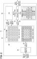
FIG. 2 shows a schematic diagram of thePE 12. - Each
PE 12 has an ALU (Arithmetic and Logic Unit) 20, an internal RAM (Random Access Memory) 22, asender 24, areceiver 26, and aqueue 28. - The
ALU 20 is an arithmetic unit that performs layer-by-layer convolution operation on the input tile. TheALU 20 in the present embodiment performs Fuse execution on the input tile. - The
internal RAM 22 is a storage medium that stores the results of layer-by-layer calculation of Fuse execution, data received fromother PEs 12, and other data. - The
sender 24 sends data to theadjacent PEs 12. Thereceiver 26 receives data from theadjacent PEs 12. ThePE 12 sends or receives overlap data to or from theadjacent PE 12 via thesender 24 and thereceiver 26. - In the
queue 28, commands, each of which indicates a relationship between the overlap data to be sent and thedestination PE 12 to which the overlap data is to be sent, are registered. Thesender 24 sends the overlap data to theadjacent PEs 12 according to the command registered in thequeue 28. - The following will describe sending and reception of overlap data by the
PE 12, which is performed in the Fuse execution according to the present embodiment, with reference toFIG. 2 andFIG. 3 . - The data input to the start layer of the multiple layers is multiple tiles, which are generated by dividing the input data into multiple elements. In the following description, the data units that configure the tile are also referred to as neuron data. The neuron data that configures the tile, which is input to the
PE 12, is referred to as input neuron data. The neuron data that configures the result of convolution operation performed by thePE 12 is referred to as output neuron data. - The tile input to the
PE 12 in the present embodiment includes overlap neuron data between theadjacent PE 12 so that only the convolution operation by the start layer can be executed. In the present embodiment of Fuse execution, overlap data is received from theadjacent PE 12 in the second and subsequent layer operation. Thus, there is no need to include the overlap data in the tile corresponding to the number of layers as in conventional Fuse execution. However, the tile that is the target of operation in the start layer cannot receive overlap data from theadjacent PE 12. Thus, the tile that is the target of operation in the start layer is required to include the overlap data in advance. The tiles generated from the input data are assigned to thePEs 12 so that the neuron data does not overlap in the second and subsequent layers of convolution operation, but the tile to be processed in the start layer includes the neuron data that overlaps with theadjacent PE 12. - The
ALU 20 of eachPE 12 performs layer-by-layer operation on the tile, which include multiple pieces ofinput neuron data 30, and stores the operation result, which corresponds to theoutput neuron data 32, in theinternal RAM 22. InFIG. 2 , regions indicated by "0, 0" to "4, 5" indicate respective locations of multiple pieces ofinput neuron data 30 that are included in the tile. - The input neuron data30 is stored in the internal RAM22, and then output to the
ALU 20, where layer-by-layer convolution operation is performed. Theoutput neuron data 32 is then output from theALU 20 as a result of the convolution operation on theinput neuron data 30, and theoutput neuron data 32 is stored in theinternal RAM 22. Theoutput neuron data 32, shown in white background inFIG. 2 , is the result of the convolution operation of theinput neuron data 30. - The
PE 12 sends theoutput neuron data 32, which is the overlap data, to theadjacent PE 12 every time the convolution operation corresponding to the layer is completed. The overlap data corresponds to the periphery data ofoutput neuron data 32 obtained by calculation executed as described above. In the example shown inFIG. 2 , among theoutput neuron data 32, the overlap data includes "1, 1", "1, 2", "1, 3", "1, 4", "2, 1", "2, 4", "3, 1", "3, 2", "3, 3", and "3, 4". - Then, the overlap data is sent to the
adjacent PE 12 based on the registered relationship in thequeue 28. In the example shown inFIG. 2 , theoutput neuron data 32 in "3, 4" is sent to theadjacent PE 12 on lower right side (SE: South East). Theoutput neuron data 32 in "3, 1" is sent to theadjacent PE 12 on lower left side (SW: South West). Theoutput neuron data 32 in "1, 4", "2, 4", and "3, 4" are sent to theadjacent PEs 12 on the right side (E). Theoutput neuron data 32 in "3, 1", "3, 2", "3, 3", and "3, 4" are sent to theadjacent PEs 12 on the lower side (S). Theoutput neuron data 32 in "1, 1", "2, 1", and "3, 1" are sent to theadjacent PEs 12 on the left side (W). Theoutput neuron data 32 in "1, 1", "1, 2", "1, 3", and "1, 4" are sent toadjacent PEs 12 on the upper side (N: North). Theoutput neuron data 32 in "1, 1" is sent to theadjacent PE 12 on the upper left side (NW). Theoutput neuron data 32 in "1, 4" is sent to theadjacent PE 12 on the upper right side (NE). -
FIG. 3 is a schematic diagram showing sending and receiving of overlap data by thePE 12.FIG. 3 shows, in (A), the tiles for which convolution operations are to be performed byrespective PEs 12 in the start layer. The hatched region indicates the overlap data that overlaps with theadjacent PE 12. The start layer corresponds toActivation 0 shown inFIG. 9 . -
FIG. 3 shows, in (B), the case where thePE 12 receives overlap data from theadjacent PE 12 before execution of the second and subsequent layer operation. As an example, the overlap data received by thePE 12 located in "1, 1" is indicated by arrows. The operation shown in (B) ofFIG. 3 corresponds toActivation 1 shown inFIG. 9 . Thus, thePE 12 in "1, 1" receives overlap data from theadjacent PEs 12 adjacent to the upper side, lower side, left side, lower right side, lower left side, upper right side, and lower right side. - When the
PE 12 receives overlap data from theadjacent PEs 12, thePE 12 performs the convolution operation in the next layer based on the convolution operation result of the previous layer and the overlap data received from theadjacent PEs 12. Specifically, theALU 20 included in thePE 12 configures a tile by mapping the overlap data received from theadjacent PEs 12 around the operation result of the previous layer, that is, by combining the overlap data with the operation result of previous layer, and then performs the convolution operation of the next layer based on the combined tile. - For example, in the
output neuron data 32 shown inFIG. 2 , the neuron data in regions of "0, 0 " to "0, 5", "1, 0", "1, 5", "2, 0", "2, 5", "3, 0", "3, 5", "4, 0" to "4, 5", which are indicated by the hatching lines, are the overlap data received fromadjacent PEs 12. As shown inFIG. 2 , the received overlap data are combined with theoutput neuron data 32 output by thePE 12 to generate theinput neuron data 30, which is the target of the convolution operation to be performed in the next layer. - The sending time of overlap data from the
PE 12 to theadjacent PEs 12 is at the end of each layer convolution operation by thePE 12 and thedestination PE 12 is ready to receive the overlap data. The calculation results of operations in the end layer obtained by the Fuse execution at eachPE 12 are stored in theexternal memory 14. - As explained above, the
calculation device 10 in the present embodiment performs CNN by Fuse execution. Then, thePE 12 included in thecalculation device 10 sends, to theadjacent PE 12, the overlap data needed in the next layer operation to be performed by theadjacent PE 12 every time the layer-by-layer convolution operation is completed. ThePE 12 performs the convolution operation in the next layer based on the overlap data received from theadjacent PEs 12 and the operation result of the previous layer. EachPE 12 repeats this sending and reception of overlap data as long as the layer of Fuse execution continues. - With the above-described configuration, the
calculation device 10 in the present embodiment can obtain the overlap data needed in each layer from theadjacent PEs 12, thereby reducing the number of duplicate operations executed in adjacent twoPEs 12 for performing the convolution operation by Fuse execution. As a result, thecalculation device 10 of the present embodiment can reduce the operation amount of convolution operation, and shorten the execution duration of convolution operation, thereby improving the power-to-performance ratio. - The following will describe a second embodiment of the present disclosure. In the present embodiment, the number of tiles generated from the input data is larger than the number of
PEs 12 provided in thecalculation device 10. - The
calculation device 10 in the present embodiment performs a loop process that assigns multiple tiles to eachPE 12 and performs operations to all of the tiles by performing multiple times of loop. Thecalculation device 10 in the present embodiment sends and receives overlap data to and from theadjacent PEs 12 for performing the Fuse execution. - The loop process of the present embodiment is described with reference to
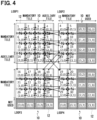
FIG. 4 andFIG. 5 .FIG. 4 is a schematic diagram showing tile assignment to thePEs 12.FIG. 5 is a schematic diagram showing exchange of overlap data from the start layer to the last layer. - In
FIG. 4 , thecalculation device 10 shown inloop 1 throughloop 4 is identical device, and the operations are performed in the order ofloop 1,loop 2,loop 3, andloop 4. As an example, thecalculation device 10 in the present embodiment includes 16PEs 12 that are arranged in a two-dimensional array with 4 rows and 4 columns. In the example shown inFIG. 4 , the input data, which is image data, is divided into 30 tiles of 6 rows and 5 columns. InFIG. 4 , the index number indicated in eachPE 12 corresponds to each divided tile, and eachPE 12 is assigned with the tile indicated by the index number and performs the convolution operation. The two-dimensional array of tiles corresponds to the location of input data, which is the image data. - In the calculation device 1- according to the present embodiment, when the number of tiles is larger than the number of
PEs 12, the number of loops is set according to the number of tiles. Then, the tiles are assigned to thePEs 12 such that the adjacent relationship ofmultiple PEs 12 match the adjacent relationship of multiple tiles and operations are performed on different tiles in each loop. After themultiple PEs 12 complete all layer operations to the assigned tiles in the current loop, the multiple PEs perform all layer operations to the assigned tiles in the next loop. This configuration allows thecalculation device 10 to perform convolution operations on all of the tiles, even when the number of tiles is larger than the number ofPEs 12. - The
multiple PEs 12 in the present embodiment are divided into two groups, that is, a mandatory tile group and an auxiliary tile group. In the following description, tiles included in the mandatory tile group are referred to as mandatory tiles, and tiles included in the auxiliary tile group are referred to as auxiliary tiles. - The auxiliary tile group includes
multiple PEs 12 arranged in periphery areas of the two-dimensional array ofPEs 12. In the example shown inFIG. 4 , thePEs 12 located in the rightmost column and bottom row correspond to the auxiliary tile group. The tiles included in the auxiliary tile group are only used to calculate the overlap data required by the operations on adjacent tiles included in the mandatory tile group. The tiles included in the auxiliary tile group are included in the mandatory tile group in the next loop. - Among the
PEs 12 arranged in two-dimensional array, thePEs 12 located in periphery area of the array do not include thePE 12 that sends or receives the overlap data. Therefore, in each loop, somePEs 12 do not send and receive overlap data which is originally required, thereby degrading the accuracy of convolution operation. In the present embodiment, thePEs 12 in the auxiliary tile group located in the periphery area of the two-dimensional array ofPEs 12 are used only to calculate the overlap data of theadjacent PE 12. This configuration improves the accuracy of convolution operation in each loop, since there are no PEs 12 in the mandatory tile group that cannot send and receive the overlap data. The tiles that are used only to calculate the overlap data in the previous loop are included in the mandatory tile group for calculation in the current and subsequent loops. - Depending on the assignment of tiles to the
PEs 12, there may be somePEs 12 where no tiles are assigned and no operations are performed.Such PEs 12 will be remained as unused. - When a tile is located at the periphery of mandatory tile group and a tile to which the overlap data is to be sent is operated in the next loop, the overlap data cannot be sent directly.
- When the tile adjacent to the tile being currently operated is included in the next and subsequent loops, the overlap data calculated layer-by-layer operation of the tile being currently operated is stored in the
external memory 14. Then, the tiles to be calculated in the next and subsequent loops are calculated using the corresponding overlap data for each layer stored in theexternal memory 14. Thus, by storing the overlap data in theexternal memory 14, the overlap data calculated in the previous loop can be used in the next and subsequent loops, eliminating the need to calculate the overlap data between current loop and the next loop. - The following will describe the exchange of overlap data between tiles according to the present embodiment, that is, sending and receiving of overlap data between the
PEs 12 with reference toFIG. 4 andFIG. 5 . - The arrows between two adjacent tiles in the loop shown in
FIG. 4 represent the exchange of overlap data between two adjacent tiles in the same loop. The arrows between two different loops indicate sending of overlap data through theexternal memory 14. - In
FIG. 5 , sending and reception of overlap data between thePEs 12 located at the upper end of the two-dimensional array ofmultiple PEs 12 is shown in the layer direction. InFIG. 5 , the lower side indicates the operation in the start layer and the upper side indicates the operation in the end layer. - As shown in
FIG. 4 andFIG. 5 , as an example, inloop 1,tile 3 in the mandatory tile group exchanges overlap data with theadjacent tile 2 and also exchanges the overlap data with theadjacent tile 4 of the auxiliary tile group while performing the convolution operation by Fuse execution. Thetile 3 stores the overlap data exchanged with theadjacent tile 4 of the auxiliary tile group in theexternal memory 14 each time a single layer operation is completed. Inloop 2, thetile 4, which is included in the mandatory tile group, receives the overlap data corresponding to each layer from theexternal memory 14 and exchanges the overlap data with theadjacent tile 5, while performing the convolution operation by Fuse execution. The final operation result of each tile obtained by performing Fuse execution to each tile is also stored in theexternal memory 14. -
FIG. 6 shows a functional block diagram of aninformation processing device 40 that performs a tile assignment process for thePEs 12. After determining the tile assignment, theinformation processing device 40 inputs the tile assignment to thecalculation device 10, for assigning the tiles to thePEs 12 to perform the CNN with Fuse execution. - The
information processing device 40 includes atile generation unit 42, aloop setting unit 44, and anassignment unit 46. - The
tile generation unit 42 divides input data, such as image data into multiple tiles. - The
loop setting unit 44 sets the number of loops according to the number of tiles and the number ofPEs 12. The method of setting the number of loops may be properly designed. In the example shown inFIG. 4 , the tile assignment to thePEs 12 is set to 4 loops according to the locations of tiles in the input data. - In the example shown in
FIG. 4 , half of thePEs 12 included inloop 2 andloop 4 are not used. As shown in the example ofFIG. 7 ,tiles loop 3 ofFIG. 4 may be assigned to the left column of theunused PEs 12 ofloop 2 as the mandatory tile group, andtiles FIG. 4 may be assigned to the right column ofunused PEs 12 ofloop 2 as the auxiliary tile group. Thetiles 17 to 20, 22 to 25, and 27 to 30 may be assigned toloop 3 as the mandatory tile group. With this assignment, the number of loops can be decreased to 3. Note that thetiles loop 2 do not exchange the overlap data with theadjacent tiles tiles 17 to 20, 22, and 27 in theloop 3 are stored inexternal memory 14. - The
assignment unit 46 determines the assignment of tiles to thePEs 12 according to the number of loops determined by theloop setting unit 44. Theassignment unit 46 assigns the tiles, which correspond to the operation targets in each loop, to thePEs 12. Theassignment unit 46 also determines the mandatory tiles and the auxiliary tiles. - In the present embodiment, tiles are divided into mandatory tile group and auxiliary tile group. As another example, the auxiliary tile group may not be set. When the auxiliary tile group is not set, some of the necessary overlap data may not be obtained, but the number of loops can be reduced. Thus, the execution duration required for the CNN can be reduced.
- In the first embodiment described above, the tiles are generated based on the input data by the
tile generation unit 42 of theinformation processing device 40, and tiles are assigned to thePEs 12 by theassignment unit 46. - The following will describe a third embodiment of the present disclosure.
- In the second embodiment, the
external memory 14 is used to exchange the overlap data between two adjacent loops. In the present embodiment, theexternal memory 14 is not used to exchange the overlap data between two adjacent loops. - In the present embodiment, the
PEs 12 that performs operations on the tiles, which are included in the auxiliary tile group in the current loop and to be included in the mandatory tile group in the next loop, are moved to another end virtually, keeping the tiles in the next loop. Theother PEs 12 are also virtually reversed in location as a result of the movement of PEs, and operations of new tiles are performed. In the following description, the virtual movement and reversal ofPEs 12 is referred to as a flip. - The following will describe the flip according to the present embodiment with reference to
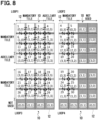
FIG. 8 . Similar toFIG. 4 , the index number in eachPE 12 indicates the tile assigned to eachPE 12 inFIG. 8 . In eachPE 12, the index number indicated by (n, m) indicates the actual location of thePE 12. - In the present embodiment, the adjacent relationship of each tile and the adjacent relationship of each
PE 12 is correlated with one another in theloop 1. ThePEs 12 that calculates the tiles included in the auxiliary tile group inloop 1 and calculates the tiles included in the mandatory tile group inloop 2 are thePEs 12 of (0, 3) to (3, 3), which are the PEs included in the fourth column, that is, the rightmost column inloop 1. Therefore,PEs 12 in locations (0, 3) to (3, 3) virtually move to the other end ofloop 2, while maintaining the calculation results ofloop 1. The calculation results include the overlap data for each layer oftiles PEs 12 in locations of (0, 3) to (3, 3) are virtually located in the rightmost column in theloop 1 and is virtually located in the leftmost column inloop 2. The leftmost column inloop 2 corresponds to the first column. - As the movement of
PEs 12 in (0, 3) to (3, 3),other PEs 12 are also virtually reversed inloop 2 from the locations inloop 1. Specifically, thePEs 12 in (0, 2) to (3, 2), which are located in the third column inLoop 1, is virtually located in the second column inLoop 2. New tiles, which are the targets of operation, are assigned to thePEs 12 in (0, 2) to (3, 2). - The
PEs 12 in (0, 1) to (3, 1), which are located in the second column inloop 1, are virtually located in the third column ofloop 2. ThePEs 12 in (0, 0) to (3, 0), which are located in the first column inloop 1, that is, the leftmost column inloop 1, are virtually located in the fourth column, that is, the rightmost column ofloop 2. In the example shown inFIG. 8 , the third and fourth columns ofPEs 12 are not used inloop 2. - The
PEs 12, which calculate tiles included in the auxiliary tile group inloop 1 and included in the mandatory tile group in theloop 3, correspond to thePEs 12 in (3, 0) to (3, 3) located at the lower end in the fourth row. ThePEs 12 in (3, 0) to (3, 3) are located at the bottom end inloop 1, but inloop 3, thePEs 12 in (3, 0) to (3, 3) are virtually located at the top end of first row. ThePEs 12 in (3, 0) to (3, 3) continues to store the calculation results including the overlap data of each layer oftiles 16 to 19 calculated inloop 1 in theinternal memory 22 such that the calculation result can be used inloop 3. - As the movement of
PEs 12 in (3, 0) to (3, 3) ofloop 1 to the new locations ofloop 3,other PEs 12 inloop 1 are also virtually reversed inloop 3 from the respective locations inloop 1. Specifically, thePEs 12 in (2, 0) to (2, 3), which are located in the third row inloop 1, are virtually located in the second row inloop 3. ThePEs 12 in (1, 0) to (1, 3), which are located in the second row inloop 1, are virtually located in the third row inloop 3. ThePEs 12, which are virtually located in the second row and the third row, are assigned with new tiles as the targets of operation. - The
PEs 12 in (0, 0) to (0, 3), which are located at the upper end of the first row inloop 1, are virtually located at the lower end of the fourth row inloop 3. In the example shown inFIG. 8 , thePEs 12 in the fourth row are not used inloop 3. - The
PEs 12 that calculates the tiles included in the auxiliary tile group inloop 3 and calculates the tiles included in the mandatory tile group inloop 4 are thePEs 12 of (3, 3) to (0, 3), which are the PEs virtually located in the fourth column, that is, the rightmost column inloop 3. ThePEs 12 in (3, 3) to (0, 0) inloop 3 are virtually located in the leftmost column of the first column in theloop 4. ThePEs 12 in (3, 3) to (1, 3) are virtually moved to the leftmost end ofloop 4 while maintaining the calculation results ofloop 3. The calculation results include the overlap data for each layer oftiles - As the movement of
PEs 12 in (3, 3) to (0, 3) ofloop 3 to the new locations ofloop 4,other PEs 12 inloop 3 are also virtually reversed inloop 4 from the respective locations inloop 3. Specifically, thePEs 12 in (3, 2) to (0, 2), which are located in the third column inloop 3, is virtually located in the second column inloop 4. New tiles, which are the targets of operation, are assigned to thePEs 12 in (3, 2) to (0, 2). - The
PEs 12 in (3, 1) to (0, 1), which are located in the second column inloop 3, are virtually located in the third column ofloop 4. ThePEs 12 in (3, 0) to (0, 0), which are located in the first column inloop 3, that is, the leftmost column inloop 3, are virtually located in the fourth column, that is, the rightmost column ofloop 4. In the example shown inFIG. 8 , the third and fourth columns ofPEs 12 are not used inloop 4. - The
calculation device 10 according to the present embodiment sets the tile locations and the index number ofPEs 12 in flipping manner each time switching to new loop. This configuration can eliminate storing of overlap data in theexternal memory 14, since the locations ofPEs 12 are virtually changed such that the results of the tiles that are calculated in the previous loop can be used in the next or subsequent loops. - Although the present disclosure is described with the embodiment and modifications as described above, the technical scope of the present disclosure is not limited to the scope described in the embodiment and modifications described above. Various changes or improvements can be made to the above embodiment and modifications without departing from the spirit of the present disclosure, and other modifications or improvements are also included in the technical scope of the present disclosure.
Claims (7)
- A calculation device (10) comprisinga plurality of processing elements (12), each of which performing an arithmetic operation on each of multiple divided data elements,whereinthe multiple divided data elements are generated by dividing input data input to the calculation device,each of the plurality of processing elements continuously performs a convolution operation on the corresponding divided data element in each of multiple layers,each of the plurality of processing elements includes:an arithmetic unit (20) performing the convolution operation on the corresponding divided data element in each of the multiple layers;a sender (24) sending data to an adjacent processing element, which is one of the plurality of processing elements; anda receiver (26) receiving data from the adjacent processing element, andwhen the convolution operation is completed in one of the multiple layers, each of the plurality of processing elements sends, to the adjacent processing element, predetermined data necessary for the convolution operation in the subsequent layer and performs the convolution operation in the subsequent layer based on the predetermined data received from the adjacent processing element and calculation result of the previous layer.
- The calculation device according to claim 1, wherein
each of the multiple divided data elements input to corresponding one of the plurality of processing elements includes data overlapping between adjacent two of the plurality of processing elements to enable the convolution operation by a first layer only among the multiple layers. - The calculation device according to claim 1 or 2, whereinthe input data is multi-dimensional array data,when the number of the multiple divided data elements is larger than the number of the plurality of processing elements, the number of loops is set according to the number of the multiple divided data elements,the multiple divided data elements are assigned to the plurality of processing elements such that an adjacent relationship of the plurality of processing elements match an adjacent relationship of the multiple divided data elements and the convolution operation are performed on different divided data elements in each of the loops, andafter the plurality of processing elements complete the convolution operation of the assigned divided data elements in all of the multiple layers in one of the loops, the plurality of processing elements perform the convolution operation of the assigned divided data elements in all of the multiple layers in the subsequent loop.
- The calculation device according to claim 3, whereinthe plurality of processing elements are divided into a first group and a second group,the second group includes a part of the plurality of processing elements, which are arranged in a periphery region of a two-dimensional arrangement of the plurality of processing elements, andthe multiple divided data elements corresponding to the second group is used only for calculation of the predetermined data, which is needed in calculation of an adjacent divided data element corresponding to the first group.
- The calculation device according to claim 4, wherein,when the adjacent divided data element, which is adjacent to the divided data element under operation in the first group, is to be operated in the subsequent loop, the predetermined data obtained from the divided data element under operation in each of the multiple layers is stored in an external memory, andthe adjacent divided data element to be operated in the subsequent loop is operated in the subsequent loop using the predetermined data stored in the external memory.
- The calculation device according to claim 4, whereinone of the plurality of processing elements, which is included in the second group and performs the convolution operation on the divided data element in the previous loop and is included in the first group and performs the convolution operation on the divided data element in the subsequent loop, is virtually moved to another end of the two-dimensional arrangement of the plurality of processing elements with the divided data element being maintained, anda location of another one of the plurality of processing elements is virtually reversed corresponding to the movement of the one of the plurality of processing elements to perform the convolution operation on the corresponding divided data element.
- A calculation method executed by a calculation device, the calculation device including a plurality of processing elements each of which performing an arithmetic operation on each of multiple divided data elements, the multiple divided data elements being generated by dividing input data input to the calculation device, each of the plurality of processing elements continuously performing a convolution operation on the corresponding divided data element in each of multiple layers, the calculation method comprising:a first process in which each of the plurality of processing elements performs the convolution operation on the corresponding divided data element input to each of the plurality of processing elements in each of the multiple layers;a second process of sending, to an adjacent processing element which is one of the plurality of processing elements, predetermined data necessary for the convolution operation in the subsequent layer every time the convolution operation is completed in one of the multiple layers; anda third process in which each of the plurality of processing elements performs the convolution operation in the subsequent layer based on the predetermined data received from the adjacent processing element and calculation result of the previous layer.
Applications Claiming Priority (2)
| Application Number | Priority Date | Filing Date | Title |
|---|---|---|---|
| JP2022036319 | 2022-03-09 | ||
| PCT/JP2023/005297 WO2023171278A1 (en) | 2022-03-09 | 2023-02-15 | Calculation device and calculation method |
Publications (2)
| Publication Number | Publication Date |
|---|---|
| EP4492263A1 true EP4492263A1 (en) | 2025-01-15 |
| EP4492263A4 EP4492263A4 (en) | 2025-07-09 |
Family
ID=87936734
Family Applications (1)
| Application Number | Title | Priority Date | Filing Date |
|---|---|---|---|
| EP23766458.6A Pending EP4492263A4 (en) | 2022-03-09 | 2023-02-15 | CALCULATING DEVICE AND CALCULATING METHOD |
Country Status (4)
| Country | Link |
|---|---|
| US (1) | US20240403383A1 (en) |
| EP (1) | EP4492263A4 (en) |
| JP (1) | JP7798172B2 (en) |
| WO (1) | WO2023171278A1 (en) |
Family Cites Families (3)
| Publication number | Priority date | Publication date | Assignee | Title |
|---|---|---|---|---|
| CN113641627A (en) * | 2015-05-21 | 2021-11-12 | 高盛有限责任公司 | General parallel computing architecture |
| WO2018071546A1 (en) * | 2016-10-11 | 2018-04-19 | The Research Foundation For The State University Of New York | System, method, and accelerator to process convolutional neural network layers |
| US11436483B2 (en) * | 2018-01-17 | 2022-09-06 | Mediatek Inc. | Neural network engine with tile-based execution |
-
2023
- 2023-02-15 WO PCT/JP2023/005297 patent/WO2023171278A1/en not_active Ceased
- 2023-02-15 JP JP2024505991A patent/JP7798172B2/en active Active
- 2023-02-15 EP EP23766458.6A patent/EP4492263A4/en active Pending
-
2024
- 2024-08-13 US US18/802,174 patent/US20240403383A1/en active Pending
Also Published As
| Publication number | Publication date |
|---|---|
| US20240403383A1 (en) | 2024-12-05 |
| JP7798172B2 (en) | 2026-01-14 |
| WO2023171278A1 (en) | 2023-09-14 |
| JPWO2023171278A1 (en) | 2023-09-14 |
| EP4492263A4 (en) | 2025-07-09 |
Similar Documents
| Publication | Publication Date | Title |
|---|---|---|
| US12288153B2 (en) | Schedule-aware tensor distribution module | |
| TWI767310B (en) | Processor, computing method, and computer program product | |
| EP3407203B1 (en) | Statically schedulable feed and drain structure for systolic array architecture | |
| US9311157B2 (en) | Method and apparatus for dynamic resource allocation of processing units on a resource allocation plane having a time axis and a processing unit axis | |
| EP3985509B1 (en) | Neural network segmentation method, prediction method, and related apparatus | |
| Liu et al. | WinoCNN: Kernel sharing Winograd systolic array for efficient convolutional neural network acceleration on FPGAs | |
| US10713042B2 (en) | Arithmetic processing device and control method for arithmetic processing device | |
| KR102238600B1 (en) | Scheduler computing device, data node of distributed computing system having the same, and method thereof | |
| CN118643253B (en) | Data processing method, device, equipment and storage medium | |
| US20230409885A1 (en) | Hardware Environment-Based Data Operation Method, Apparatus and Device, and Storage Medium | |
| CN115328439B (en) | An incremental matrix multiplication accelerator for HPC/AI applications | |
| JP2024040198A (en) | Sharding for synchronous processors | |
| CN117649474A (en) | Picture-oriented multi-GPU rendering system, method and device and storage medium | |
| EP4492263A1 (en) | Calculation device and calculation method | |
| Xiao et al. | FCNNLib: An efficient and flexible convolution algorithm library on FPGAs | |
| WO2016024508A1 (en) | Multiprocessor device | |
| US12254416B2 (en) | Compiler for implementing neural network accelerator | |
| JP2017167581A (en) | Parallel computer, FFT operation program, and FFT operation method | |
| US11687831B1 (en) | Method, product, and apparatus for a multidimensional processing array for hardware acceleration of convolutional neural network inference | |
| US10198293B2 (en) | Distributed real-time computing framework using in-storage processing | |
| CN119576580A (en) | Data scheduling method and device, electronic device and medium | |
| TWI887757B (en) | Computer-implemented method of propagation latency reduction in neural network and data processing apparatus | |
| CN110415162B (en) | Adaptive graph partitioning method facing heterogeneous fusion processor in big data | |
| Pan et al. | A fast MER enumeration algorithm for online task placement on reconfigurable FPGAs | |
| US20040216119A1 (en) | Method for load balancing an n-dimensional array of parallel processing elements |
Legal Events
| Date | Code | Title | Description |
|---|---|---|---|
| STAA | Information on the status of an ep patent application or granted ep patent |
Free format text: STATUS: THE INTERNATIONAL PUBLICATION HAS BEEN MADE |
|
| PUAI | Public reference made under article 153(3) epc to a published international application that has entered the european phase |
Free format text: ORIGINAL CODE: 0009012 |
|
| STAA | Information on the status of an ep patent application or granted ep patent |
Free format text: STATUS: REQUEST FOR EXAMINATION WAS MADE |
|
| 17P | Request for examination filed |
Effective date: 20241002 |
|
| AK | Designated contracting states |
Kind code of ref document: A1 Designated state(s): AL AT BE BG CH CY CZ DE DK EE ES FI FR GB GR HR HU IE IS IT LI LT LU LV MC ME MK MT NL NO PL PT RO RS SE SI SK SM TR |
|
| REG | Reference to a national code |
Ref country code: DE Ref legal event code: R079 Free format text: PREVIOUS MAIN CLASS: G06F0017100000 Ipc: G06N0003063000 |
|
| STAA | Information on the status of an ep patent application or granted ep patent |
Free format text: STATUS: EXAMINATION IS IN PROGRESS |
|
| DAV | Request for validation of the european patent (deleted) | ||
| DAX | Request for extension of the european patent (deleted) | ||
| A4 | Supplementary search report drawn up and despatched |
Effective date: 20250605 |
|
| RIC1 | Information provided on ipc code assigned before grant |
Ipc: G06F 17/10 20060101ALI20250530BHEP Ipc: G06F 15/80 20060101ALI20250530BHEP Ipc: G06F 17/15 20060101ALI20250530BHEP Ipc: G06N 3/0464 20230101ALI20250530BHEP Ipc: G06N 3/063 20230101AFI20250530BHEP |
|
| 17Q | First examination report despatched |
Effective date: 20250617 |