EP4492205A1 - Display control system, display control method, and program - Google Patents
Display control system, display control method, and program Download PDFInfo
- Publication number
- EP4492205A1 EP4492205A1 EP23766600.3A EP23766600A EP4492205A1 EP 4492205 A1 EP4492205 A1 EP 4492205A1 EP 23766600 A EP23766600 A EP 23766600A EP 4492205 A1 EP4492205 A1 EP 4492205A1
- Authority
- EP
- European Patent Office
- Prior art keywords
- section
- display
- information
- vibration
- head
- Prior art date
- Legal status (The legal status is an assumption and is not a legal conclusion. Google has not performed a legal analysis and makes no representation as to the accuracy of the status listed.)
- Pending
Links
Images



Classifications
-
- G—PHYSICS
- G06—COMPUTING OR CALCULATING; COUNTING
- G06F—ELECTRIC DIGITAL DATA PROCESSING
- G06F1/00—Details not covered by groups G06F3/00 - G06F13/00 and G06F21/00
- G06F1/16—Constructional details or arrangements
- G06F1/1613—Constructional details or arrangements for portable computers
- G06F1/163—Wearable computers, e.g. on a belt
-
- G—PHYSICS
- G06—COMPUTING OR CALCULATING; COUNTING
- G06F—ELECTRIC DIGITAL DATA PROCESSING
- G06F3/00—Input arrangements for transferring data to be processed into a form capable of being handled by the computer; Output arrangements for transferring data from processing unit to output unit, e.g. interface arrangements
- G06F3/01—Input arrangements or combined input and output arrangements for interaction between user and computer
- G06F3/016—Input arrangements with force or tactile feedback as computer generated output to the user
-
- B—PERFORMING OPERATIONS; TRANSPORTING
- B06—GENERATING OR TRANSMITTING MECHANICAL VIBRATIONS IN GENERAL
- B06B—METHODS OR APPARATUS FOR GENERATING OR TRANSMITTING MECHANICAL VIBRATIONS OF INFRASONIC, SONIC, OR ULTRASONIC FREQUENCY, e.g. FOR PERFORMING MECHANICAL WORK IN GENERAL
- B06B1/00—Methods or apparatus for generating mechanical vibrations of infrasonic, sonic, or ultrasonic frequency
- B06B1/02—Methods or apparatus for generating mechanical vibrations of infrasonic, sonic, or ultrasonic frequency making use of electrical energy
- B06B1/04—Methods or apparatus for generating mechanical vibrations of infrasonic, sonic, or ultrasonic frequency making use of electrical energy operating with electromagnetism
- B06B1/045—Methods or apparatus for generating mechanical vibrations of infrasonic, sonic, or ultrasonic frequency making use of electrical energy operating with electromagnetism using vibrating magnet, armature or coil system
-
- G—PHYSICS
- G01—MEASURING; TESTING
- G01H—MEASUREMENT OF MECHANICAL VIBRATIONS OR ULTRASONIC, SONIC OR INFRASONIC WAVES
- G01H1/00—Measuring characteristics of vibrations in solids by using direct conduction to the detector
-
- G—PHYSICS
- G02—OPTICS
- G02B—OPTICAL ELEMENTS, SYSTEMS OR APPARATUS
- G02B27/00—Optical systems or apparatus not provided for by any of the groups G02B1/00 - G02B26/00, G02B30/00
- G02B27/01—Head-up displays
- G02B27/017—Head mounted
-
- G—PHYSICS
- G02—OPTICS
- G02B—OPTICAL ELEMENTS, SYSTEMS OR APPARATUS
- G02B27/00—Optical systems or apparatus not provided for by any of the groups G02B1/00 - G02B26/00, G02B30/00
- G02B27/01—Head-up displays
- G02B27/017—Head mounted
- G02B27/0172—Head mounted characterised by optical features
-
- G—PHYSICS
- G02—OPTICS
- G02B—OPTICAL ELEMENTS, SYSTEMS OR APPARATUS
- G02B27/00—Optical systems or apparatus not provided for by any of the groups G02B1/00 - G02B26/00, G02B30/00
- G02B27/01—Head-up displays
- G02B27/017—Head mounted
- G02B27/0176—Head mounted characterised by mechanical features
-
- G—PHYSICS
- G02—OPTICS
- G02B—OPTICAL ELEMENTS, SYSTEMS OR APPARATUS
- G02B27/00—Optical systems or apparatus not provided for by any of the groups G02B1/00 - G02B26/00, G02B30/00
- G02B27/02—Viewing or reading apparatus
-
- G—PHYSICS
- G06—COMPUTING OR CALCULATING; COUNTING
- G06F—ELECTRIC DIGITAL DATA PROCESSING
- G06F3/00—Input arrangements for transferring data to be processed into a form capable of being handled by the computer; Output arrangements for transferring data from processing unit to output unit, e.g. interface arrangements
- G06F3/01—Input arrangements or combined input and output arrangements for interaction between user and computer
- G06F3/011—Arrangements for interaction with the human body, e.g. for user immersion in virtual reality
Definitions
- the present invention relates to a display control system, a display control method, and a program.
- head-mounted displays that present a moving image such as a game video or a movie have been used.
- Using a head-mounted display enables a user to view a moving image spreading in front of the eyes of the user and to obtain high presence.
- the present invention has been devised in view of the circumstances described above, and one of objects of the present invention is to analyze whether or not there is a possibility that an end user using a head-mounted display has a sense of incongruity caused by vibration.
- a display control system including a first acquisition section configured to acquire control information for controlling, according to a video displayed on a display section of a head-mounted display, a vibration section that causes the head-mounted display to vibrate, a second acquisition section configured to acquire actual vibration information relating to actual vibration of the head-mounted display, and a display control section configured to cause at least the control information and the actual vibration information to be displayed together on a single screen.
- a display control method including a procedure of acquiring control information for controlling, according to a video displayed on a display section of a head-mounted display, a vibration section that causes the head-mounted display to vibrate, a procedure of acquiring actual vibration information relating to actual vibration of the head-mounted display, and a procedure of causing at least the control information and the actual vibration information to be displayed together on a single screen.
- FIG. 1 is a diagram illustrating an example of an entire configuration of a display control system according to the present embodiment.
- a display control system 10 preferably includes, for example, a head-mounted display (hereinafter referred to also as an HMD) 12, an entertainment apparatus 14, a relay apparatus 16, a television 18, a camera/microphone unit 20, a controller 22, and an analysis apparatus 60.
- HMD head-mounted display
- the analysis apparatus 60 is a computer (information processing apparatus) used by a person (hereinafter referred to as an analyzer) who analyzes a vibration state of the HMD 12 provided with a vibration function before the HMD 12 is provided to an end user.
- an analyzer analyzing the vibration state of the HMD 12 with use of the analysis apparatus 60, it is made possible to provide the end user with the HMD 12 that realizes comfortable vibration.
- a developer of the HMD 12 adjust the level and timing of vibration according to the vibration state analyzed by the analyzer, before the HMD 12 is provided to the end user.
- the end user is preferably a consumer who purchases and uses the HMD 12.
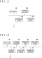
- FIG. 2 is a diagram illustrating an example of a configuration of the entertainment apparatus according to the present embodiment.
- the entertainment apparatus 14 preferably includes a processor 50, a storage section 52, a communication section 54, and an input/output section 56.
- the entertainment apparatus 14 preferably is, for example, a computer such as a game console, a digital versatile disc (DVD) player, or a Blu-ray (registered trademark) player.
- the entertainment apparatus 14 according to the present embodiment preferably generates a video and sound by, for example, executing a game program or reproducing content which program and content are stored therein or recorded in an optical disk. Then, the entertainment apparatus 14 according to the present embodiment preferably outputs a video signal representing the generated video and an audio signal representing the generated sound to the television 18, the HMD 12, and the analysis apparatus 60 via the relay apparatus 16.
- the processor 50 preferably is, for example, a program control device such as a central processing unit (CPU) that operates in accordance with a program installed in the entertainment apparatus 14.
- a program control device such as a central processing unit (CPU) that operates in accordance with a program installed in the entertainment apparatus 14.
- the storage section 52 preferably is, for example, a storage element such as a read-only memory (ROM) or a random access memory (RAM), a hard disk drive, or the like.
- the storage section 52 preferably stores therein the program to be executed by the processor 50 and the like.
- the communication section 54 preferably is, for example, a communication interface such as a wireless local area network (LAN) module.
- the input/output section 56 preferably is an input/output port such as a high-definition multimedia interface (registered trademark) (HDMI) port or a universal serial bus (USB) port.
- HDMI high-definition multimedia interface
- USB universal serial bus
- the components provided in the entertainment apparatus 14 may be incorporated in the HMD 12.
- the HMD 12 preferably includes a main body 121 and a fastening band 122.
- the fastening band 122 preferably is, as a whole, in an annular shape to surround the head of the user.
- the main body 121 preferably includes a housing 44 that accommodates a display section 38 and the like and that forms an exterior of the main body 121.
- the fastening band 122 preferably is connected to an upper portion of the main body 121.
- FIG. 3 is a diagram illustrating an example of a configuration of the head-mounted display according to the present embodiment.
- the HMD 12 preferably includes a processor 30, a storage section 32, a communication section 34, an input/output section 36, the display section 38, a detection section 40, and a vibration section 42.
- the processor 30 preferably is, for example, a program control device such as a microprocessor that operates in accordance with a program installed in the HMD 12.
- the storage section 32 preferably is, for example, a storage element such as a ROM or a RAM.
- the storage section 32 preferably stores therein the program to be executed by the processor 30 and the like.
- the communication section 34 preferably is, for example, a communication interface such as a wireless LAN module. It is to be noted that, while the HMD 12 in the example illustrated in FIG. 1 is capable of communication with the entertainment apparatus 14 by wireless communication, the HMD 12 may have a configuration capable of wired communication.
- the input/output section 36 preferably is, for example, an input/output port such as an HDMI (registered trademark) port or a USB port.
- the display section 38 is, for example, a display such as a liquid crystal display or an organic electroluminescent (EL) display and preferably causes the video generated by the entertainment apparatus 14 and the like to be displayed thereon.
- the display section 38 preferably is disposed in front of the eyes of the user in the state in which the user wears the HMD 12.
- the display section 38 preferably receives the video signal output by the entertainment apparatus 14 and relayed by the relay apparatus 16, for example, and outputs the video represented by this video signal.
- the display section 38 preferably is, for example, capable of displaying a three-dimensional image by displaying an image for the left eye and an image for the right eye. It is to be noted that the display section 38 is not limited to the one that displays a three-dimensional image, and may be one that is only capable of displaying a two-dimensional image.
- the detection section 40 preferably is a sensor having a function of detecting a posture of the HMD 12.
- the detection section 40 preferably is an inertial measurement unit (IMU) including a gyro sensor and an acceleration sensor.
- the detection section 40 preferably outputs a detection result to the processor 30.
- the processor 30 preferably calculates a vibration frequency (hereinafter referred to as a detected vibration frequency) estimated from the detection result supplied from the detection section 40.
- the detected vibration frequency preferably is a vibration frequency of the HMD 12 estimated from an angular velocity, acceleration, or the like detected by the detection section 40.
- the detection section 40 is not limited to the IMU and may be a sensor capable of detecting an actual rotational frequency of a motor provided in the vibration section 42.
- the processor 30 preferably calculates the detected vibration frequency of the HMD 12 on the basis of the detected actual rotational frequency of the motor.
- the vibration section 42 preferably is, for example, a vibration device constituting what is generally called an eccentric motor.
- the vibration section 42 is driven (vibrates) in accordance with an instruction received from the entertainment apparatus 14.
- the vibration section 42 preferably is disposed in a front portion of the fastening band 122.
- FIG. 1 illustrates arrangement of the vibration section 42 and also schematically illustrates the shape of the vibration section 42.
- the vibration section 42 is only required to be provided in the HMD 12 to cause the HMD 12 to vibrate, and is not limited to the arrangement illustrated in FIG. 1 .
- the vibration section 42 preferably vibrates, for example, when an object or a game character operated by the user makes some action or receives an impact.
- the fastening band 122 vibrates, and this vibration is transmitted to the head of the user. Accordingly, the user can have an experience with high presence.
- FIG. 4 is a diagram illustrating an example of a configuration of the analysis apparatus according to the present embodiment.
- the analysis apparatus 60 preferably includes a processor 61, a storage section 62, a communication section 63, an input/output section 64, a display section 65, and a notification section 66.
- the processor 61 preferably is, for example, a program control device such as a microprocessor that operates in accordance with a program installed in the analysis apparatus 60.
- the storage section 62 preferably is, for example, a storage element such as a ROM or a RAM.
- the storage section 62 preferably stores therein the program to be executed by the processor 61 and the like.
- the communication section 63 preferably is, for example, a communication interface such as a wireless LAN module.
- the input/output section 64 preferably is, for example, an input/output port such as an HDMI (registered trademark) port or a USB port.
- the display section 65 preferably is, for example, a display such as a liquid crystal display or an organic EL display.
- the notification section 66 preferably is, for example, a loudspeaker for notifying the analyzer of the vibration state of the HMD 12 by sound or the like.
- each computer described above is not limited to the above examples, and various kinds of hardware can be applied.
- a reading section an optical disk drive or a memory card slot, for example
- a program and data stored in the information storage medium may be supplied to the computer via the reading section or the input/output section.
- FIG. 5 is a functional block diagram illustrating an example of functions implemented in the analysis apparatus according to the present embodiment.
- the analysis apparatus 60 preferably includes a first acquisition section 611, a second acquisition section 612, a determination section 613, a display control section 614, and a notification control section 615. These functions preferably are implemented mainly by the processor 61.
- the first acquisition section 611 acquires control information for controlling the driving of the vibration section 42.
- the control information preferably is, for example, a video signal generated by the entertainment apparatus 14 or a driving signal for controlling a driving force to be supplied to a coil in the vibration section 42 according to the video signal.
- the control information is a driving signal.
- the second acquisition section 612 acquires actual vibration information relating to the actual vibration of the HMD 12.
- the actual vibration information preferably is a detection value detected by the detection section 40 or information based on the detection value. More specifically, the actual vibration information preferably includes the detected vibration frequency of the HMD 12. The actual vibration information further preferably includes the acceleration, angular velocity, and the like of the HMD 12.
- the determination section 613 determines whether or not the vibration of the HMD 12 is comfortable for the end user, on the basis of one of or both the control information acquired by the first acquisition section 611 and the actual vibration information acquired by the second acquisition section 612. For example, the determination section 613 preferably determines whether or not the vibration of the HMD 12 is comfortable, on the basis of a frequency of the driving signal supplied to the vibration section 42 and a period of time during which the first acquisition section 611 continuously acquires this driving signal. Alternatively, for example, the determination section 613 preferably determines whether or not the vibration of the HMD 12 is comfortable, on the basis of the detected vibration frequency of the HMD 12 and a period of time during which the first acquisition section 612 continuously acquires this detected vibration frequency.
- the determination section 613 preferably determines that the vibration is uncomfortable. This is because the end user may feel uncomfortable when large vibration continues for a long period of time.
- the determination section 613 may determine whether or not the vibration is generated as intended by the developer, by comparing the control information and the actual vibration information with each other. More specifically, the determination section 613 may determine whether or not the detected vibration frequency deviates from the frequency of the driving signal supplied to the vibration section 42.
- the display control section 614 causes a screen of the display section 65 to display at least the control information acquired by the first acquisition section 611 and the actual vibration information acquired by the second acquisition section 612 together. Further, the display control section 614 preferably causes the screen of the display section 65 to display the determination result by the determination section 613 together with the control information and the actual vibration information.
- the display control section 614 preferably causes the screen of the display section 65 to display the determination result, for example, when a predetermined period of time set in advance for each vibration frequency has passed. By checking the displayed determination result, the analyzer can recognize that the vibration is generated in excess of an allowable range within which the end user feels comfortable.
- the display control section 614 preferably causes the screen of the display section 65 to display a determination result of "Frequency Range 1" when a driving signal having a vibration frequency of 20 to 25 [Hz] is supplied continuously for 1.5 seconds. Further, for example, the display control section 614 preferably causes the screen of the display section 65 to display a determination result of "Frequency Range 2" when a driving signal having a vibration frequency of 16 to 19 [Hz] is supplied continuously for 10 seconds. Further, for example, the display control section 614 preferably causes the screen of the display section 65 to display a determination result of "Frequency Range 3" when a driving signal having a vibration frequency of 15 [Hz] or lower is supplied continuously for 60 seconds.
- the analyzer can recognize that such a video that a driving signal having a vibration frequency of 15 [Hz] or lower is supplied continuously for a long period of time is displayed on the display section 38 of the HMD 12. It is to be noted that details of a display state on the display section 65 will be described later with reference to FIG. 6 . In addition, numerical values of the vibration frequency mentioned here and the displayed determination results are merely examples and not restrictive.
- the display control section 614 is not limited to the one that causes the determination result to be displayed only when the determination section 613 determines that the vibration is uncomfortable, and may be one that causes the determination result to be displayed during a period during which the determination by the determination section 613 indicates that the vibration is not uncomfortable (the vibration is comfortable).
- the display control section 614 may cause the display section 38 of the HMD 12, as well as the display section 65, to display a screen image including information similar to that of a screen image described later with reference to FIG. 6 .
- the analyzer himself/herself wears the HMD 12 to check the vibration state in some cases. However, since wearing the HMD 12 blocks a view of the surroundings, the analyzer cannot visually recognize the display section 65 of the analysis apparatus 60. To cope with this problem, display is preformed on the display section 38 provided in the HMD 12, so that the analyzer wearing the HMD 12 can be notified of the determination result.
- the notification control section 615 preferably notifies a wearer wearing the HMD 12 of the determination result by the determination section 613, by use of the notification section 66.
- the analyzer himself/herself wears the HMD 12 to check the vibration state in some cases.
- the analyzer cannot visually recognize the display section 65 of the analysis apparatus 60.
- sound is issued for notification of the determination result, so that the analyzer wearing the HMD 12 can be notified of the determination result.
- the notification of the determination result may not only be performed by the notification section 65 of the analysis apparatus 60, but also be performed by a loudspeaker provided in a device other than the analysis apparatus 60.
- FIG. 6 is a diagram illustrating an example of the screen image displayed on the display section of the analysis apparatus according to the present embodiment.
- the display control section 614 displays vibration information 201 indicated as "Vibration View,” HMD posture information 202 indicated as “HMD Pose,” game screen image information 203 indicated as “Game View,” determination result information 204 indicated as “Notification,” and sound information 205 indicated as “Sound View” together on the display section 65.
- the vibration information 201 includes driving signal information 201a that is control information indicated as "request frequency” and actual vibration information 201b indicated as "actual result.”
- the driving signal information 201a in FIG. 6 is illustrated as a waveform graph with the time set on the axis of abscissa and the vibration frequency set on the axis of ordinate.
- the actual vibration information 201b includes acceleration information 201b1 indicated as a waveform graph with the time set on the axis of abscissa and the acceleration of the vibration section 42 set on the axis of ordinate and detected vibration frequency information 201b2 indicated as a waveform graph with the time set on the axis of abscissa and the detected vibration frequency set on the axis of ordinate.
- the actual vibration information 201b is only required to be information detected by the detection section 40 and may include angular velocity information or the like of the HMD 12, for example.
- the time axis for the driving signal information 201a and the time axis for the actual vibration information 201b preferably are displayed side by side on the same scale.
- the driving signal information 201a and the actual vibration information 201b preferably are displayed simultaneously on the screen of the display section 65. This enables the analyzer to comparatively check the driving signal supplied to the vibration section 42 and the information relating to the actual vibration of the vibration section 42 at each timing by viewing the display section 65. Thus, the analyzer can check whether or not the vibration is delayed with respect to the video.
- the HMD posture information 202 preferably is a video including how the HMD 12 externally appears when the second acquisition section 612 acquires the actual vibration information.
- the HMD posture information 202 preferably is displayed on the basis of an output from an imaging device such as a camera that photographs, during the analysis, the wearer wearing the HMD 12. It is to be noted that the HMD posture information 202 is not limited to a photographed video and may be displayed using computer graphics (CG).
- CG computer graphics
- the game screen image information 203 preferably represents a video at the time when the second acquisition section 612 acquires the actual vibration information. More specifically, the game screen image information 203 preferably is a game screen image displayed on the television 18 when the second acquisition section 612 acquires the actual vibration information.
- the HMD posture information 202 and the game screen image information 203 are displayed together with the vibration information 201. This enables the analyzer to check the posture of the HMD 12, the video of the game screen image, and the vibration state of the HMD 12 simultaneously.
- the display control section 614 causes the determination result information 204 based on the determination result by the determination section 613 to be displayed on the screen of the display section 65.
- the determination result display information 204 indicated as "Notification” is displayed on the screen of the display section 65.
- the determination result is "Frequency Range 2" described above.
- the determination result information 204 does not need to be displayed all the time, and may be displayed only when there is the possibility that the end user feels uncomfortable. Further, the determination result information 204 may be displayed as emphasized characters, for example, bold or colored characters. This makes it easier for the analyzer to visually recognize the possibility that the end user feels uncomfortable.
- the sound information 205 indicated as a waveform graph with the time set on the axis of abscissa and the volume of sound set on the axis of ordinate is displayed on the screen of the display section 65.
- the time axis for the sound information 205 and the time axis for the vibration information 201 preferably are displayed side by side on the same scale. This enables the analyzer to comparatively check the driving signal supplied to the vibration section 42, the state of the actual vibration of the vibration section 42, and the sound output according to the video displayed on the display section 38 of the HMD 12, at each timing by viewing the display section 65. For example, the analyzer can check if the vibration of the HMD 12 is delayed or earlier with respect to the sound output according to the video.
- the screen image illustrated in FIG. 6 is merely an example, and a screen image including other unillustrated information may be displayed.
- the arrangement of the respective pieces of information is also not limited to the example illustrated in FIG. 6 , and it may be possible to adjust the arrangement as appropriate in an easy-to-see manner for the analyzer.
- the screen image illustrated in FIG. 6 may be displayed not only on the screen of the display section 65 of the analysis apparatus 60 but also on the television 18 or the screen of the display section 38 of the HMD 12.
- FIG. 7 is a flow chart illustrating an example of processing executed in the analysis apparatus according to the present embodiment.
- the first acquisition section 611 acquires the control information (step S1).
- the second acquisition section 612 acquires the actual vibration information (step S2).
- the display control section 614 causes the control information and the actual vibration information to be displayed together on the screen of the display section 65 and the like (step S3).
- the determination section 613 determines whether or not a period of time during which vibration having a predetermined vibration frequency continues has exceeded a predetermined period of time (step S4).
- the display control section 614 causes the determination result to be displayed together with the control information and the actual vibration information on the screen of the display section 65 and the like (step S5).
- the display control section 614 preferably causes the determination result to be continuously displayed for approximately several seconds (10 seconds, for example) and then stops the display of the determination result. With the display of the determination result continued for a certain period of time and then stopped, it is easy for the analyzer to visually recognize what kind of situation is displayed in the video when the vibration of the HMD 12 causes discomfort.
Landscapes
- Engineering & Computer Science (AREA)
- Physics & Mathematics (AREA)
- General Physics & Mathematics (AREA)
- General Engineering & Computer Science (AREA)
- Theoretical Computer Science (AREA)
- Optics & Photonics (AREA)
- Human Computer Interaction (AREA)
- Computer Hardware Design (AREA)
- Electromagnetism (AREA)
- Mechanical Engineering (AREA)
- User Interface Of Digital Computer (AREA)
Abstract
Description
- The present invention relates to a display control system, a display control method, and a program.
- As disclosed in PTL 1, head-mounted displays that present a moving image such as a game video or a movie have been used. Using a head-mounted display enables a user to view a moving image spreading in front of the eyes of the user and to obtain high presence.
-
- There is a demand for obtaining higher presence while using a head-mounted display. To meet this demand, for example, it is possible to use a vibration motor to generate vibration according to a video. With such a configuration, if there is a time lag between visually recognized information and a bodily sensation obtained from vibration, for example, if the vibration is delayed with respect to the video, the presence cannot be produced as expected. This causes an end user to have a sense of incongruity.
- The present invention has been devised in view of the circumstances described above, and one of objects of the present invention is to analyze whether or not there is a possibility that an end user using a head-mounted display has a sense of incongruity caused by vibration.
- In order to solve the above problem, according to the present invention, there is provided a display control system including a first acquisition section configured to acquire control information for controlling, according to a video displayed on a display section of a head-mounted display, a vibration section that causes the head-mounted display to vibrate, a second acquisition section configured to acquire actual vibration information relating to actual vibration of the head-mounted display, and a display control section configured to cause at least the control information and the actual vibration information to be displayed together on a single screen.
- Further, according to the present invention, there is provided a display control method including a procedure of acquiring control information for controlling, according to a video displayed on a display section of a head-mounted display, a vibration section that causes the head-mounted display to vibrate, a procedure of acquiring actual vibration information relating to actual vibration of the head-mounted display, and a procedure of causing at least the control information and the actual vibration information to be displayed together on a single screen.
- Further, according to the present invention, there is provided a program for causing a computer to execute a procedure of acquiring control information for controlling, according to a video displayed on a display section of a head-mounted display, a vibration section that causes the head-mounted display to vibrate, a procedure of acquiring actual vibration information relating to actual vibration of the head-mounted display, and a procedure of causing at least the control information and the actual vibration information to be displayed together on a single screen.
-
- [
FIG. 1 ]
FIG. 1 is a diagram illustrating an example of an entire configuration of a display control system according to the present embodiment. - [
FIG. 2 ]
FIG. 2 is a diagram illustrating an example of a configuration of an entertainment apparatus according to the present embodiment. - [
FIG. 3 ]
FIG. 3 is a diagram illustrating an example of a configuration of a head-mounted display according to the present embodiment. - [
FIG. 4 ]
FIG. 4 is a diagram illustrating an example of a configuration of an analysis apparatus according to the present embodiment. - [
FIG. 5 ]
FIG. 5 is a functional block diagram illustrating an example of functions implemented in the analysis apparatus according to the present embodiment. - [
FIG. 6 ]
FIG. 6 is a diagram illustrating an example of a screen image displayed on a display section of the analysis apparatus according to the present embodiment. - [
FIG. 7 ]
FIG. 7 is a flow chart illustrating an example of processing executed in the analysis apparatus according to the present embodiment. - An embodiment of the present invention (hereinafter referred to as the present embodiment) will be described below with reference to the drawings.
-
FIG. 1 is a diagram illustrating an example of an entire configuration of a display control system according to the present embodiment. As illustrated inFIG. 1 , adisplay control system 10 according to the present embodiment preferably includes, for example, a head-mounted display (hereinafter referred to also as an HMD) 12, anentertainment apparatus 14, arelay apparatus 16, atelevision 18, a camera/microphone unit 20, acontroller 22, and ananalysis apparatus 60. It is to be noted that the entire configuration of thedisplay control system 10 illustrated inFIG. 1 is merely an example and not restrictive. For example, thetelevision 18, the camera/microphone unit 20, and therelay apparatus 16 may not be included. - The
analysis apparatus 60 is a computer (information processing apparatus) used by a person (hereinafter referred to as an analyzer) who analyzes a vibration state of theHMD 12 provided with a vibration function before theHMD 12 is provided to an end user. By the analyzer analyzing the vibration state of theHMD 12 with use of theanalysis apparatus 60, it is made possible to provide the end user with theHMD 12 that realizes comfortable vibration. For example, it is preferable that a developer of theHMD 12 adjust the level and timing of vibration according to the vibration state analyzed by the analyzer, before theHMD 12 is provided to the end user. It is to be noted that the end user is preferably a consumer who purchases and uses the HMD 12. -
FIG. 2 is a diagram illustrating an example of a configuration of the entertainment apparatus according to the present embodiment. As illustrated inFIG. 2 , for example, theentertainment apparatus 14 according to the present embodiment preferably includes aprocessor 50, astorage section 52, acommunication section 54, and an input/output section 56. - The
entertainment apparatus 14 preferably is, for example, a computer such as a game console, a digital versatile disc (DVD) player, or a Blu-ray (registered trademark) player. Theentertainment apparatus 14 according to the present embodiment preferably generates a video and sound by, for example, executing a game program or reproducing content which program and content are stored therein or recorded in an optical disk. Then, theentertainment apparatus 14 according to the present embodiment preferably outputs a video signal representing the generated video and an audio signal representing the generated sound to thetelevision 18, theHMD 12, and theanalysis apparatus 60 via therelay apparatus 16. - The
processor 50 preferably is, for example, a program control device such as a central processing unit (CPU) that operates in accordance with a program installed in theentertainment apparatus 14. - The
storage section 52 preferably is, for example, a storage element such as a read-only memory (ROM) or a random access memory (RAM), a hard disk drive, or the like. Thestorage section 52 preferably stores therein the program to be executed by theprocessor 50 and the like. Thecommunication section 54 preferably is, for example, a communication interface such as a wireless local area network (LAN) module. The input/output section 56 preferably is an input/output port such as a high-definition multimedia interface (registered trademark) (HDMI) port or a universal serial bus (USB) port. - It is to be noted that the components provided in the
entertainment apparatus 14 may be incorporated in the HMD 12. - As illustrated in
FIG. 1 , the HMD 12 preferably includes amain body 121 and afastening band 122. Thefastening band 122 preferably is, as a whole, in an annular shape to surround the head of the user. Themain body 121 preferably includes ahousing 44 that accommodates adisplay section 38 and the like and that forms an exterior of themain body 121. Thefastening band 122 preferably is connected to an upper portion of themain body 121. -
FIG. 3 is a diagram illustrating an example of a configuration of the head-mounted display according to the present embodiment. As illustrated inFIG. 3 , the HMD 12 preferably includes aprocessor 30, astorage section 32, acommunication section 34, an input/output section 36, thedisplay section 38, adetection section 40, and avibration section 42. - The
processor 30 preferably is, for example, a program control device such as a microprocessor that operates in accordance with a program installed in theHMD 12. Thestorage section 32 preferably is, for example, a storage element such as a ROM or a RAM. Thestorage section 32 preferably stores therein the program to be executed by theprocessor 30 and the like. Thecommunication section 34 preferably is, for example, a communication interface such as a wireless LAN module. It is to be noted that, while theHMD 12 in the example illustrated inFIG. 1 is capable of communication with theentertainment apparatus 14 by wireless communication, theHMD 12 may have a configuration capable of wired communication. The input/output section 36 preferably is, for example, an input/output port such as an HDMI (registered trademark) port or a USB port. - The
display section 38 is, for example, a display such as a liquid crystal display or an organic electroluminescent (EL) display and preferably causes the video generated by theentertainment apparatus 14 and the like to be displayed thereon. Thedisplay section 38 preferably is disposed in front of the eyes of the user in the state in which the user wears theHMD 12. Thedisplay section 38 preferably receives the video signal output by theentertainment apparatus 14 and relayed by therelay apparatus 16, for example, and outputs the video represented by this video signal. - The
display section 38 preferably is, for example, capable of displaying a three-dimensional image by displaying an image for the left eye and an image for the right eye. It is to be noted that thedisplay section 38 is not limited to the one that displays a three-dimensional image, and may be one that is only capable of displaying a two-dimensional image. - The
detection section 40 preferably is a sensor having a function of detecting a posture of theHMD 12. For example, thedetection section 40 preferably is an inertial measurement unit (IMU) including a gyro sensor and an acceleration sensor. Thedetection section 40 preferably outputs a detection result to theprocessor 30. In addition, theprocessor 30 preferably calculates a vibration frequency (hereinafter referred to as a detected vibration frequency) estimated from the detection result supplied from thedetection section 40. It is to be noted that the detected vibration frequency preferably is a vibration frequency of theHMD 12 estimated from an angular velocity, acceleration, or the like detected by thedetection section 40. It is to be noted that thedetection section 40 is not limited to the IMU and may be a sensor capable of detecting an actual rotational frequency of a motor provided in thevibration section 42. In this case, theprocessor 30 preferably calculates the detected vibration frequency of theHMD 12 on the basis of the detected actual rotational frequency of the motor. - The
vibration section 42 preferably is, for example, a vibration device constituting what is generally called an eccentric motor. Thevibration section 42 is driven (vibrates) in accordance with an instruction received from theentertainment apparatus 14. As illustrated inFIG. 1 , for example, thevibration section 42 preferably is disposed in a front portion of thefastening band 122. It is to be noted thatFIG. 1 illustrates arrangement of thevibration section 42 and also schematically illustrates the shape of thevibration section 42. Thevibration section 42 is only required to be provided in theHMD 12 to cause theHMD 12 to vibrate, and is not limited to the arrangement illustrated inFIG. 1 . - The
vibration section 42 preferably vibrates, for example, when an object or a game character operated by the user makes some action or receives an impact. Along with the vibration of thevibration section 42, thefastening band 122 vibrates, and this vibration is transmitted to the head of the user. Accordingly, the user can have an experience with high presence. -
FIG. 4 is a diagram illustrating an example of a configuration of the analysis apparatus according to the present embodiment. As illustrated inFIG. 4 , theanalysis apparatus 60 preferably includes aprocessor 61, astorage section 62, acommunication section 63, an input/output section 64, adisplay section 65, and anotification section 66. - The
processor 61 preferably is, for example, a program control device such as a microprocessor that operates in accordance with a program installed in theanalysis apparatus 60. Thestorage section 62 preferably is, for example, a storage element such as a ROM or a RAM. Thestorage section 62 preferably stores therein the program to be executed by theprocessor 61 and the like. Thecommunication section 63 preferably is, for example, a communication interface such as a wireless LAN module. The input/output section 64 preferably is, for example, an input/output port such as an HDMI (registered trademark) port or a USB port. - The
display section 65 preferably is, for example, a display such as a liquid crystal display or an organic EL display. Thenotification section 66 preferably is, for example, a loudspeaker for notifying the analyzer of the vibration state of theHMD 12 by sound or the like. - The hardware configuration of each computer described above is not limited to the above examples, and various kinds of hardware can be applied. For example, a reading section (an optical disk drive or a memory card slot, for example) for reading a computer-readable information storage medium may be included. For example, a program and data stored in the information storage medium may be supplied to the computer via the reading section or the input/output section.
-
FIG. 5 is a functional block diagram illustrating an example of functions implemented in the analysis apparatus according to the present embodiment. As illustrated inFIG. 5 , theanalysis apparatus 60 preferably includes afirst acquisition section 611, asecond acquisition section 612, adetermination section 613, adisplay control section 614, and anotification control section 615. These functions preferably are implemented mainly by theprocessor 61. - The
first acquisition section 611 acquires control information for controlling the driving of thevibration section 42. The control information preferably is, for example, a video signal generated by theentertainment apparatus 14 or a driving signal for controlling a driving force to be supplied to a coil in thevibration section 42 according to the video signal. In the example described in the present embodiment, the control information is a driving signal. - The
second acquisition section 612 acquires actual vibration information relating to the actual vibration of theHMD 12. The actual vibration information preferably is a detection value detected by thedetection section 40 or information based on the detection value. More specifically, the actual vibration information preferably includes the detected vibration frequency of theHMD 12. The actual vibration information further preferably includes the acceleration, angular velocity, and the like of theHMD 12. - The
determination section 613 determines whether or not the vibration of theHMD 12 is comfortable for the end user, on the basis of one of or both the control information acquired by thefirst acquisition section 611 and the actual vibration information acquired by thesecond acquisition section 612. For example, thedetermination section 613 preferably determines whether or not the vibration of theHMD 12 is comfortable, on the basis of a frequency of the driving signal supplied to thevibration section 42 and a period of time during which thefirst acquisition section 611 continuously acquires this driving signal. Alternatively, for example, thedetermination section 613 preferably determines whether or not the vibration of theHMD 12 is comfortable, on the basis of the detected vibration frequency of theHMD 12 and a period of time during which thefirst acquisition section 612 continuously acquires this detected vibration frequency. In a case where the detected vibration frequency of theHMD 12 is high and the period of time during which the detected vibration frequency is continuously acquired is long, for example, thedetermination section 613 preferably determines that the vibration is uncomfortable. This is because the end user may feel uncomfortable when large vibration continues for a long period of time. - In addition, for example, the
determination section 613 may determine whether or not the vibration is generated as intended by the developer, by comparing the control information and the actual vibration information with each other. More specifically, thedetermination section 613 may determine whether or not the detected vibration frequency deviates from the frequency of the driving signal supplied to thevibration section 42. - The
display control section 614 causes a screen of thedisplay section 65 to display at least the control information acquired by thefirst acquisition section 611 and the actual vibration information acquired by thesecond acquisition section 612 together. Further, thedisplay control section 614 preferably causes the screen of thedisplay section 65 to display the determination result by thedetermination section 613 together with the control information and the actual vibration information. - The
display control section 614 preferably causes the screen of thedisplay section 65 to display the determination result, for example, when a predetermined period of time set in advance for each vibration frequency has passed. By checking the displayed determination result, the analyzer can recognize that the vibration is generated in excess of an allowable range within which the end user feels comfortable. - More specifically, for example, the
display control section 614 preferably causes the screen of thedisplay section 65 to display a determination result of "Frequency Range 1" when a driving signal having a vibration frequency of 20 to 25 [Hz] is supplied continuously for 1.5 seconds. Further, for example, thedisplay control section 614 preferably causes the screen of thedisplay section 65 to display a determination result of "Frequency Range 2" when a driving signal having a vibration frequency of 16 to 19 [Hz] is supplied continuously for 10 seconds. Further, for example, thedisplay control section 614 preferably causes the screen of thedisplay section 65 to display a determination result of "Frequency Range 3" when a driving signal having a vibration frequency of 15 [Hz] or lower is supplied continuously for 60 seconds. These determination results indicate that the end user may possibly feel uncomfortable in the respective frequency bands. In the case of observing "Frequency Range 3" displayed on the screen of thedisplay section 65, for example, the analyzer can recognize that such a video that a driving signal having a vibration frequency of 15 [Hz] or lower is supplied continuously for a long period of time is displayed on thedisplay section 38 of theHMD 12. It is to be noted that details of a display state on thedisplay section 65 will be described later with reference toFIG. 6 . In addition, numerical values of the vibration frequency mentioned here and the displayed determination results are merely examples and not restrictive. - It is to be noted that the
display control section 614 is not limited to the one that causes the determination result to be displayed only when thedetermination section 613 determines that the vibration is uncomfortable, and may be one that causes the determination result to be displayed during a period during which the determination by thedetermination section 613 indicates that the vibration is not uncomfortable (the vibration is comfortable). - Moreover, the
display control section 614 may cause thedisplay section 38 of theHMD 12, as well as thedisplay section 65, to display a screen image including information similar to that of a screen image described later with reference toFIG. 6 . The analyzer himself/herself wears theHMD 12 to check the vibration state in some cases. However, since wearing theHMD 12 blocks a view of the surroundings, the analyzer cannot visually recognize thedisplay section 65 of theanalysis apparatus 60. To cope with this problem, display is preformed on thedisplay section 38 provided in theHMD 12, so that the analyzer wearing theHMD 12 can be notified of the determination result. - The
notification control section 615 preferably notifies a wearer wearing theHMD 12 of the determination result by thedetermination section 613, by use of thenotification section 66. The analyzer himself/herself wears theHMD 12 to check the vibration state in some cases. However, since wearing theHMD 12 blocks the view of the surroundings, the analyzer cannot visually recognize thedisplay section 65 of theanalysis apparatus 60. To cope with this problem, sound is issued for notification of the determination result, so that the analyzer wearing theHMD 12 can be notified of the determination result. It is to be noted that the notification of the determination result may not only be performed by thenotification section 65 of theanalysis apparatus 60, but also be performed by a loudspeaker provided in a device other than theanalysis apparatus 60. - All or some of the above-described functions provided in the
analysis apparatus 60 according to the present embodiment may be implemented by another computer. -
FIG. 6 is a diagram illustrating an example of the screen image displayed on the display section of the analysis apparatus according to the present embodiment. In the example illustrated inFIG. 6 , thedisplay control section 614 displaysvibration information 201 indicated as "Vibration View,"HMD posture information 202 indicated as "HMD Pose," gamescreen image information 203 indicated as "Game View," determination resultinformation 204 indicated as "Notification," andsound information 205 indicated as "Sound View" together on thedisplay section 65. - In the example illustrated in
FIG. 6 , thevibration information 201 includes drivingsignal information 201a that is control information indicated as "request frequency" andactual vibration information 201b indicated as "actual result." - The driving
signal information 201a inFIG. 6 is illustrated as a waveform graph with the time set on the axis of abscissa and the vibration frequency set on the axis of ordinate. - Further, in the example illustrated in
FIG. 6 , theactual vibration information 201b includes acceleration information 201b1 indicated as a waveform graph with the time set on the axis of abscissa and the acceleration of thevibration section 42 set on the axis of ordinate and detected vibration frequency information 201b2 indicated as a waveform graph with the time set on the axis of abscissa and the detected vibration frequency set on the axis of ordinate. It is to be noted that theactual vibration information 201b is only required to be information detected by thedetection section 40 and may include angular velocity information or the like of theHMD 12, for example. - In addition, as illustrated in
FIG. 6 , the time axis for the drivingsignal information 201a and the time axis for theactual vibration information 201b preferably are displayed side by side on the same scale. Further, the drivingsignal information 201a and theactual vibration information 201b preferably are displayed simultaneously on the screen of thedisplay section 65. This enables the analyzer to comparatively check the driving signal supplied to thevibration section 42 and the information relating to the actual vibration of thevibration section 42 at each timing by viewing thedisplay section 65. Thus, the analyzer can check whether or not the vibration is delayed with respect to the video. - The
HMD posture information 202 preferably is a video including how theHMD 12 externally appears when thesecond acquisition section 612 acquires the actual vibration information. TheHMD posture information 202 preferably is displayed on the basis of an output from an imaging device such as a camera that photographs, during the analysis, the wearer wearing theHMD 12. It is to be noted that theHMD posture information 202 is not limited to a photographed video and may be displayed using computer graphics (CG). - The game
screen image information 203 preferably represents a video at the time when thesecond acquisition section 612 acquires the actual vibration information. More specifically, the gamescreen image information 203 preferably is a game screen image displayed on thetelevision 18 when thesecond acquisition section 612 acquires the actual vibration information. - In the present embodiment, the
HMD posture information 202 and the gamescreen image information 203 are displayed together with thevibration information 201. This enables the analyzer to check the posture of theHMD 12, the video of the game screen image, and the vibration state of theHMD 12 simultaneously. - Moreover, in the present embodiment, the
display control section 614 causes the determination resultinformation 204 based on the determination result by thedetermination section 613 to be displayed on the screen of thedisplay section 65. In the example illustrated inFIG. 6 , the determinationresult display information 204 indicated as "Notification" is displayed on the screen of thedisplay section 65. More specifically, in the example illustrated inFIG. 6 , the determination result is "Frequency Range 2" described above. Such a display enables the analyzer to recognize in what kind of posture theHMD 12 is and what kind of situation is displayed in the video of the game screen image when there is a possibility that the end user feels uncomfortable. - It is to be noted that the determination result
information 204 does not need to be displayed all the time, and may be displayed only when there is the possibility that the end user feels uncomfortable. Further, the determination resultinformation 204 may be displayed as emphasized characters, for example, bold or colored characters. This makes it easier for the analyzer to visually recognize the possibility that the end user feels uncomfortable. - In addition, in the example illustrated in
FIG. 6 , thesound information 205 indicated as a waveform graph with the time set on the axis of abscissa and the volume of sound set on the axis of ordinate is displayed on the screen of thedisplay section 65. The time axis for thesound information 205 and the time axis for thevibration information 201 preferably are displayed side by side on the same scale. This enables the analyzer to comparatively check the driving signal supplied to thevibration section 42, the state of the actual vibration of thevibration section 42, and the sound output according to the video displayed on thedisplay section 38 of theHMD 12, at each timing by viewing thedisplay section 65. For example, the analyzer can check if the vibration of theHMD 12 is delayed or earlier with respect to the sound output according to the video. - The screen image illustrated in
FIG. 6 is merely an example, and a screen image including other unillustrated information may be displayed. The arrangement of the respective pieces of information is also not limited to the example illustrated inFIG. 6 , and it may be possible to adjust the arrangement as appropriate in an easy-to-see manner for the analyzer. Furthermore, the screen image illustrated inFIG. 6 may be displayed not only on the screen of thedisplay section 65 of theanalysis apparatus 60 but also on thetelevision 18 or the screen of thedisplay section 38 of theHMD 12. - Description will now be made of an example of a flow of processing executed in the
analysis apparatus 60 according to the present embodiment with reference to a flow chart illustrated inFIG. 7. FIG. 7 is a flow chart illustrating an example of processing executed in the analysis apparatus according to the present embodiment. - First, the
first acquisition section 611 acquires the control information (step S1). Next, thesecond acquisition section 612 acquires the actual vibration information (step S2). Thereafter, thedisplay control section 614 causes the control information and the actual vibration information to be displayed together on the screen of thedisplay section 65 and the like (step S3). - Further, the
determination section 613 determines whether or not a period of time during which vibration having a predetermined vibration frequency continues has exceeded a predetermined period of time (step S4). When thedetermination section 613 determines that the period of time during which the vibration having the predetermined vibration frequency continues has exceeded the predetermined period of time (YES in step S4), thedisplay control section 614 causes the determination result to be displayed together with the control information and the actual vibration information on the screen of thedisplay section 65 and the like (step S5). For example, thedisplay control section 614 preferably causes the determination result to be continuously displayed for approximately several seconds (10 seconds, for example) and then stops the display of the determination result. With the display of the determination result continued for a certain period of time and then stopped, it is easy for the analyzer to visually recognize what kind of situation is displayed in the video when the vibration of theHMD 12 causes discomfort.
Claims (12)
- A display control system comprising:a first acquisition section configured to acquire control information for controlling, according to a video displayed on a display section of a head-mounted display, a vibration section that causes the head-mounted display to vibrate;a second acquisition section configured to acquire actual vibration information relating to actual vibration of the head-mounted display; anda display control section configured to cause at least the control information and the actual vibration information to be displayed together on a single screen.
- The display control system according to claim 1, further comprising:a determination section configured to determine whether or not the vibration of the head-mounted display is comfortable, on a basis of at least either the control information or the actual vibration information, whereinthe display control section causes a determination result by the determination section to be displayed together with the control information and the actual vibration information on the single screen.
- The display control system according to claim 2, whereinthe determination section determines that the vibration of the head-mounted display causes discomfort, when a period of time during which the control information or the actual vibration information is continuously acquired has exceeded a predetermined period of time, andthe display control system causes the determination result that the vibration of the head-mounted display causes discomfort to be displayed together with the control information and the actual vibration information on the single screen.
- The display control system according to claim 3, wherein
the predetermined period of time is set in advance for each vibration frequency. - The display control system according to any one of claims 1 to 4, whereinthe control information is displayed on the single screen as a waveform graph with time set on an axis of abscissa and a vibration frequency set on an axis of ordinate,the actual vibration information is displayed on the single screen as a waveform graph with the time set on an axis of abscissa and the vibration frequency set on an axis of ordinate, andthe axis of abscissa for the control information and the axis of abscissa for the actual vibration information are displayed side by side on a same scale.
- The display control system according to any one of claims 2 to 5, further comprising:
a notification control section configured to notify a wearer wearing the head-mounted display of the determination result by sound. - The display control system according to any one of claims 1 to 6, wherein
a screen of the display section of the head-mounted display includes the single screen. - The display control system according to any one of claims 1 to 7, wherein
at least either a screen of a display section provided in an information processing apparatus connected to the head-mounted display in a communicable manner or a screen of a television connected to the head-mounted display in a communicable manner includes the single screen. - The display control system according to any one of claims 1 to 8, wherein
the display control section causes at least a video including how the head-mounted display externally appears when the second acquisition section acquires the actual vibration information, to be displayed together with the control information and the actual vibration information on the single screen. - A vibration state notification system according to any one of claims 1 to 9, wherein
the display control section causes at least a video displayed on the display section of the head-mounted display when the second acquisition section acquires the actual vibration information, to be displayed together with the control information and the actual vibration information on the single screen. - A display control method comprising:a procedure of acquiring control information for controlling, according to a video displayed on a display section of a head-mounted display, a vibration section that causes the head-mounted display to vibrate;a procedure of acquiring actual vibration information relating to actual vibration of the head-mounted display; anda procedure of causing at least the control information and the actual vibration information to be displayed together on a single screen.
- A program for causing a computer to execute:a procedure of acquiring control information for controlling, according to a video displayed on a display section of a head-mounted display, a vibration section that causes the head-mounted display to vibrate;a procedure of acquiring actual vibration information relating to actual vibration of the head-mounted display; anda procedure of causing at least the control information and the actual vibration information to be displayed together on a single screen.
Applications Claiming Priority (2)
| Application Number | Priority Date | Filing Date | Title |
|---|---|---|---|
| JP2022037238 | 2022-03-10 | ||
| PCT/JP2023/006820 WO2023171422A1 (en) | 2022-03-10 | 2023-02-24 | Display control system, display control method, and program |
Publications (2)
| Publication Number | Publication Date |
|---|---|
| EP4492205A1 true EP4492205A1 (en) | 2025-01-15 |
| EP4492205A4 EP4492205A4 (en) | 2026-02-25 |
Family
ID=87935095
Family Applications (1)
| Application Number | Title | Priority Date | Filing Date |
|---|---|---|---|
| EP23766600.3A Pending EP4492205A4 (en) | 2022-03-10 | 2023-02-24 | Display Control System, Display Control Method and Program |
Country Status (4)
| Country | Link |
|---|---|
| US (1) | US12613581B2 (en) |
| EP (1) | EP4492205A4 (en) |
| JP (1) | JPWO2023171422A1 (en) |
| WO (1) | WO2023171422A1 (en) |
Family Cites Families (11)
| Publication number | Priority date | Publication date | Assignee | Title |
|---|---|---|---|---|
| JP2001189902A (en) * | 1999-12-28 | 2001-07-10 | Nec Corp | Method for controlling head-mounted display and head- mounted display device |
| EP3119082B1 (en) | 2014-03-14 | 2025-03-26 | Sony Interactive Entertainment Inc. | Head-mounted display |
| JP6589844B2 (en) * | 2016-12-21 | 2019-10-16 | 京セラドキュメントソリューションズ株式会社 | Display control apparatus and display control method |
| JP6903137B2 (en) | 2017-08-29 | 2021-07-14 | 株式会社ソニー・インタラクティブエンタテインメント | Vibration control device |
| CN108132707B (en) | 2017-11-30 | 2021-06-01 | 青岛海高设计制造有限公司 | Vibration feedback test method and test platform |
| CN108415556B (en) | 2018-01-29 | 2021-04-20 | 瑞声科技(新加坡)有限公司 | Motor vibration control method and device |
| CN108596834B (en) * | 2018-04-27 | 2023-11-17 | 腾讯科技(深圳)有限公司 | Image resolution processing method, image processing device and system, storage medium |
| CN119544947A (en) | 2018-11-01 | 2025-02-28 | 索尼互动娱乐股份有限公司 | VR motion sickness reduction system, head mounted display, VR motion sickness reduction method |
| WO2020157978A1 (en) * | 2019-02-01 | 2020-08-06 | 株式会社ソニー・インタラクティブエンタテインメント | Information processing device |
| JP6843314B1 (en) | 2019-09-11 | 2021-03-17 | 三菱電機株式会社 | Numerical control device, numerical control method and machine learning device |
| JP2021067877A (en) * | 2019-10-25 | 2021-04-30 | 株式会社ソニー・インタラクティブエンタテインメント | Information processing device, head-mounted display, and image display method |
-
2023
- 2023-02-24 EP EP23766600.3A patent/EP4492205A4/en active Pending
- 2023-02-24 WO PCT/JP2023/006820 patent/WO2023171422A1/en not_active Ceased
- 2023-02-24 US US18/840,496 patent/US12613581B2/en active Active
- 2023-02-24 JP JP2024506069A patent/JPWO2023171422A1/ja active Pending
Also Published As
| Publication number | Publication date |
|---|---|
| US20250181164A1 (en) | 2025-06-05 |
| JPWO2023171422A1 (en) | 2023-09-14 |
| EP4492205A4 (en) | 2026-02-25 |
| US12613581B2 (en) | 2026-04-28 |
| WO2023171422A1 (en) | 2023-09-14 |
Similar Documents
| Publication | Publication Date | Title |
|---|---|---|
| US11244427B2 (en) | Image resolution processing method, system, and apparatus, storage medium, and device | |
| EP3486707A1 (en) | Perception based predictive tracking for head mounted displays | |
| US20230280834A1 (en) | Vr sickness reduction system, head-mounted display, vr sickness reduction method, and program | |
| EP3588447B1 (en) | Image processing device, image processing method, and image system | |
| JP2020042369A (en) | Information processing apparatus, information processing method and recording medium | |
| JP6838902B2 (en) | Pseudo-experience providing device, simulated experience providing method, simulated experience providing system, and program | |
| JP2896291B2 (en) | Image display device | |
| KR20180055637A (en) | Electronic apparatus and method for controlling thereof | |
| EP3316571A1 (en) | Head-mounted display, notification device, notification system, notification method, and program | |
| US12613581B2 (en) | Display control system, display control method, and program | |
| WO2016072327A1 (en) | Head mounted display and information processing method | |
| KR20190083464A (en) | Electronic device controlling image display based on scroll input and method thereof | |
| US7940295B2 (en) | Image display apparatus and control method thereof | |
| US20220270330A1 (en) | Information processing device, information processing method, and program | |
| US20250153048A1 (en) | Notification control system, notification control method, and program | |
| US20240119643A1 (en) | Image processing device, image processing method, and computer-readable storage medium | |
| JP7592471B2 (en) | Information processing device, information processing method, and program | |
| CN119682680B (en) | Vehicle anti-carsickness control method and device, medium and vehicle | |
| US20240320934A1 (en) | Information processing apparatus for warning user of collision with physical object in cross reality (xr) experience, information processing method, and storage medium | |
| US12633048B2 (en) | Information processing apparatus, information processing method, and non-transitory computer readable medium | |
| CN115886816B (en) | VR/AR equipment and fatigue detection method based on same | |
| US12429945B2 (en) | Information processing apparatus and adjustment screen display method | |
| US20240257450A1 (en) | Information processing apparatus, information processing method, and non-transitory computer readable medium | |
| CN112673624B (en) | Display control device, display control method, and recording medium | |
| JP7611682B2 (en) | Information processing device, information processing method, and program |
Legal Events
| Date | Code | Title | Description |
|---|---|---|---|
| STAA | Information on the status of an ep patent application or granted ep patent |
Free format text: STATUS: THE INTERNATIONAL PUBLICATION HAS BEEN MADE |
|
| PUAI | Public reference made under article 153(3) epc to a published international application that has entered the european phase |
Free format text: ORIGINAL CODE: 0009012 |
|
| STAA | Information on the status of an ep patent application or granted ep patent |
Free format text: STATUS: REQUEST FOR EXAMINATION WAS MADE |
|
| 17P | Request for examination filed |
Effective date: 20240911 |
|
| AK | Designated contracting states |
Kind code of ref document: A1 Designated state(s): AL AT BE BG CH CY CZ DE DK EE ES FI FR GB GR HR HU IE IS IT LI LT LU LV MC ME MK MT NL NO PL PT RO RS SE SI SK SM TR |
|
| DAV | Request for validation of the european patent (deleted) | ||
| DAX | Request for extension of the european patent (deleted) | ||
| A4 | Supplementary search report drawn up and despatched |
Effective date: 20260127 |
|
| RIC1 | Information provided on ipc code assigned before grant |
Ipc: G06F 3/01 20060101AFI20260121BHEP Ipc: G06F 3/0481 20220101ALI20260121BHEP Ipc: B06B 1/04 20060101ALI20260121BHEP Ipc: G02B 27/01 20060101ALI20260121BHEP Ipc: G06F 1/16 20060101ALI20260121BHEP Ipc: G01H 1/00 20060101ALI20260121BHEP Ipc: G02B 27/02 20060101ALI20260121BHEP |