EP4492194A1 - Auxiliary module to support printed circuit assembly of electronic device - Google Patents
Auxiliary module to support printed circuit assembly of electronic device Download PDFInfo
- Publication number
- EP4492194A1 EP4492194A1 EP24186889.2A EP24186889A EP4492194A1 EP 4492194 A1 EP4492194 A1 EP 4492194A1 EP 24186889 A EP24186889 A EP 24186889A EP 4492194 A1 EP4492194 A1 EP 4492194A1
- Authority
- EP
- European Patent Office
- Prior art keywords
- pca
- cooling component
- auxiliary
- auxiliary module
- cooling
- Prior art date
- Legal status (The legal status is an assumption and is not a legal conclusion. Google has not performed a legal analysis and makes no representation as to the accuracy of the status listed.)
- Pending
Links
Images




Classifications
-
- H—ELECTRICITY
- H05—ELECTRIC TECHNIQUES NOT OTHERWISE PROVIDED FOR
- H05K—PRINTED CIRCUITS; CASINGS OR CONSTRUCTIONAL DETAILS OF ELECTRIC APPARATUS; MANUFACTURE OF ASSEMBLAGES OF ELECTRICAL COMPONENTS
- H05K7/00—Constructional details common to different types of electric apparatus
- H05K7/20—Modifications to facilitate cooling, ventilating, or heating
- H05K7/20218—Modifications to facilitate cooling, ventilating, or heating using a liquid coolant without phase change in electronic enclosures
- H05K7/20272—Accessories for moving fluid, for expanding fluid, for connecting fluid conduits, for distributing fluid, for removing gas or for preventing leakage, e.g. pumps, tanks or manifolds
-
- H—ELECTRICITY
- H05—ELECTRIC TECHNIQUES NOT OTHERWISE PROVIDED FOR
- H05K—PRINTED CIRCUITS; CASINGS OR CONSTRUCTIONAL DETAILS OF ELECTRIC APPARATUS; MANUFACTURE OF ASSEMBLAGES OF ELECTRICAL COMPONENTS
- H05K1/00—Printed circuits
- H05K1/02—Details
- H05K1/0201—Thermal arrangements, e.g. for cooling, heating or preventing overheating
- H05K1/0203—Cooling of mounted components
-
- G—PHYSICS
- G06—COMPUTING OR CALCULATING; COUNTING
- G06F—ELECTRIC DIGITAL DATA PROCESSING
- G06F1/00—Details not covered by groups G06F3/00 - G06F13/00 and G06F21/00
- G06F1/16—Constructional details or arrangements
- G06F1/20—Cooling means
-
- G—PHYSICS
- G06—COMPUTING OR CALCULATING; COUNTING
- G06F—ELECTRIC DIGITAL DATA PROCESSING
- G06F1/00—Details not covered by groups G06F3/00 - G06F13/00 and G06F21/00
- G06F1/16—Constructional details or arrangements
- G06F1/18—Packaging or power distribution
- G06F1/183—Internal mounting support structures, e.g. for supporting printed circuit boards
- G06F1/185—Mounting of expansion boards
-
- H—ELECTRICITY
- H01—ELECTRIC ELEMENTS
- H01R—ELECTRICALLY-CONDUCTIVE CONNECTIONS; STRUCTURAL ASSOCIATIONS OF A PLURALITY OF MUTUALLY-INSULATED ELECTRICAL CONNECTING ELEMENTS; COUPLING DEVICES; CURRENT COLLECTORS
- H01R12/00—Structural associations of a plurality of mutually-insulated electrical connecting elements, specially adapted for printed circuits, e.g. printed circuit boards [PCB], flat or ribbon cables, or like generally planar structures, e.g. terminal strips, terminal blocks; Coupling devices specially adapted for printed circuits, flat or ribbon cables, or like generally planar structures; Terminals specially adapted for contact with, or insertion into, printed circuits, flat or ribbon cables, or like generally planar structures
- H01R12/70—Coupling devices
- H01R12/71—Coupling devices for rigid printing circuits or like structures
-
- H—ELECTRICITY
- H01—ELECTRIC ELEMENTS
- H01R—ELECTRICALLY-CONDUCTIVE CONNECTIONS; STRUCTURAL ASSOCIATIONS OF A PLURALITY OF MUTUALLY-INSULATED ELECTRICAL CONNECTING ELEMENTS; COUPLING DEVICES; CURRENT COLLECTORS
- H01R12/00—Structural associations of a plurality of mutually-insulated electrical connecting elements, specially adapted for printed circuits, e.g. printed circuit boards [PCB], flat or ribbon cables, or like generally planar structures, e.g. terminal strips, terminal blocks; Coupling devices specially adapted for printed circuits, flat or ribbon cables, or like generally planar structures; Terminals specially adapted for contact with, or insertion into, printed circuits, flat or ribbon cables, or like generally planar structures
- H01R12/70—Coupling devices
- H01R12/91—Coupling devices allowing relative movement between coupling parts, e.g. floating or self aligning
-
- H—ELECTRICITY
- H05—ELECTRIC TECHNIQUES NOT OTHERWISE PROVIDED FOR
- H05K—PRINTED CIRCUITS; CASINGS OR CONSTRUCTIONAL DETAILS OF ELECTRIC APPARATUS; MANUFACTURE OF ASSEMBLAGES OF ELECTRICAL COMPONENTS
- H05K1/00—Printed circuits
- H05K1/02—Details
- H05K1/14—Structural association of two or more printed circuits
- H05K1/144—Stacked arrangements of planar printed circuit boards
-
- H—ELECTRICITY
- H05—ELECTRIC TECHNIQUES NOT OTHERWISE PROVIDED FOR
- H05K—PRINTED CIRCUITS; CASINGS OR CONSTRUCTIONAL DETAILS OF ELECTRIC APPARATUS; MANUFACTURE OF ASSEMBLAGES OF ELECTRICAL COMPONENTS
- H05K7/00—Constructional details common to different types of electric apparatus
- H05K7/20—Modifications to facilitate cooling, ventilating, or heating
- H05K7/2039—Modifications to facilitate cooling, ventilating, or heating characterised by the heat transfer by conduction from the heat generating element to a dissipating body
- H05K7/20436—Inner thermal coupling elements in heat dissipating housings, e.g. protrusions or depressions integrally formed in the housing
- H05K7/2049—Pressing means used to urge contact, e.g. springs
-
- H—ELECTRICITY
- H05—ELECTRIC TECHNIQUES NOT OTHERWISE PROVIDED FOR
- H05K—PRINTED CIRCUITS; CASINGS OR CONSTRUCTIONAL DETAILS OF ELECTRIC APPARATUS; MANUFACTURE OF ASSEMBLAGES OF ELECTRICAL COMPONENTS
- H05K7/00—Constructional details common to different types of electric apparatus
- H05K7/20—Modifications to facilitate cooling, ventilating, or heating
- H05K7/2039—Modifications to facilitate cooling, ventilating, or heating characterised by the heat transfer by conduction from the heat generating element to a dissipating body
- H05K7/20509—Multiple-component heat spreaders; Multi-component heat-conducting support plates; Multi-component non-closed heat-conducting structures
-
- H—ELECTRICITY
- H05—ELECTRIC TECHNIQUES NOT OTHERWISE PROVIDED FOR
- H05K—PRINTED CIRCUITS; CASINGS OR CONSTRUCTIONAL DETAILS OF ELECTRIC APPARATUS; MANUFACTURE OF ASSEMBLAGES OF ELECTRICAL COMPONENTS
- H05K7/00—Constructional details common to different types of electric apparatus
- H05K7/20—Modifications to facilitate cooling, ventilating, or heating
- H05K7/20709—Modifications to facilitate cooling, ventilating, or heating for server racks or cabinets; for data centers, e.g. 19-inch computer racks
-
- H—ELECTRICITY
- H05—ELECTRIC TECHNIQUES NOT OTHERWISE PROVIDED FOR
- H05K—PRINTED CIRCUITS; CASINGS OR CONSTRUCTIONAL DETAILS OF ELECTRIC APPARATUS; MANUFACTURE OF ASSEMBLAGES OF ELECTRICAL COMPONENTS
- H05K7/00—Constructional details common to different types of electric apparatus
- H05K7/20—Modifications to facilitate cooling, ventilating, or heating
- H05K7/2089—Modifications to facilitate cooling, ventilating, or heating for power electronics, e.g. for inverters for controlling motor
- H05K7/209—Heat transfer by conduction from internal heat source to heat radiating structure
-
- H—ELECTRICITY
- H05—ELECTRIC TECHNIQUES NOT OTHERWISE PROVIDED FOR
- H05K—PRINTED CIRCUITS; CASINGS OR CONSTRUCTIONAL DETAILS OF ELECTRIC APPARATUS; MANUFACTURE OF ASSEMBLAGES OF ELECTRICAL COMPONENTS
- H05K7/00—Constructional details common to different types of electric apparatus
- H05K7/20—Modifications to facilitate cooling, ventilating, or heating
- H05K7/2089—Modifications to facilitate cooling, ventilating, or heating for power electronics, e.g. for inverters for controlling motor
- H05K7/20927—Liquid coolant without phase change
-
- H—ELECTRICITY
- H01—ELECTRIC ELEMENTS
- H01R—ELECTRICALLY-CONDUCTIVE CONNECTIONS; STRUCTURAL ASSOCIATIONS OF A PLURALITY OF MUTUALLY-INSULATED ELECTRICAL CONNECTING ELEMENTS; COUPLING DEVICES; CURRENT COLLECTORS
- H01R12/00—Structural associations of a plurality of mutually-insulated electrical connecting elements, specially adapted for printed circuits, e.g. printed circuit boards [PCB], flat or ribbon cables, or like generally planar structures, e.g. terminal strips, terminal blocks; Coupling devices specially adapted for printed circuits, flat or ribbon cables, or like generally planar structures; Terminals specially adapted for contact with, or insertion into, printed circuits, flat or ribbon cables, or like generally planar structures
- H01R12/70—Coupling devices
- H01R12/7076—Coupling devices for connection between PCB and component, e.g. display
Definitions
- An electronic device such as a computing device, a network device, or the like may include one or more printed circuit assemblies (PCAs) which include electronic components.
- the electronic components may include primary electronic components such as processing resources (e.g., a central processing unit (CPU), graphical processing unit (GPU), System-on-Chip (Soc), Application Specific Integrated Circuit (ASIC), etc.), and secondary or auxiliary electronic components (e.g., voltage regulators, network interfaces, etc.) that support the operations of the primary electronic components and/or provide supplemental or auxiliary functions for the electronic device.
- processing resources e.g., a central processing unit (CPU), graphical processing unit (GPU), System-on-Chip (Soc), Application Specific Integrated Circuit (ASIC), etc.
- secondary or auxiliary electronic components e.g., voltage regulators, network interfaces, etc.
- one or more primary electronic components and one or more auxiliary electronic components may be part of the same PCA and are mounted to the same circuit board of the PCA.
- auxiliary electronic components such as voltage regulators or other power conversion components that supply electronic power to the processing resources.
- typically electronic devices may include a primary PCA (e.g., a motherboard or a main PCA) having a circuit board, one or more processors (primary electronic components), and one or more voltage regulators (auxiliary electronic components) for supplying the electronic power to the processors, where the processors and the voltage regulators are disposed on the circuit board.
- a primary PCA e.g., a motherboard or a main PCA
- processors primary electronic components
- voltage regulators auxiliary electronic components
- each of the auxiliary electronic components may generate heat. If such heat is not dissipated, temperatures of the auxiliary electronic components may exceed their thermal specifications, thus resulting in degraded performance, reliability, and life expectancy of the individual electronic components and/or the electronic device, as a whole.
- the electronic device may include a thermal management device to remove heat.
- the thermal management device may include a cooling device (e.g., a cold plate) that is disposed in thermal contact with the electronic components to remove the heat away from such electronic components.
- one or more of primary electronic components e.g., the processing resources
- one or more auxiliary electronic components e.g., voltage regulators
- a primary PCA e.g., a motherboard or a main PCA
- One potential drawback of this implementation is that, if one of the electronic components of the primary PCA fails, it may be difficult to repair or replace the failed electronic component without risking collateral damage to the primary PCA. Because of the risk of collateral damage, specialized tools and procedures may be needed and much care may need to be taken during the repair/replacement, and this may increase the costs of the repair/replacement.
- Another potential drawback of the above-described implementation with the primary electronic component (e.g., processing resources) and the auxiliary electronic components (e.g., voltage regulators) being co-located on the same circuit board is that, in some cases, the signal wiring for communicating signals to and from the processing resources and the power wiring for providing power from the voltage regulators to the processing resources may compete for the same limited space within the available layers of the circuit board, and sometimes there may be insufficient space for both. This difficulty is becoming more common as electronic components become more complicated and consume more power. Moreover, providing more layers in the circuit board to accommodate all the signaling and power needs may not always be feasible, as it may increase the circuit board thickness, increase cost, and/or reduce signal integrity.
- auxiliary electronic components as part of a separate, replaceable, PCA instead of imbedding them in the primary PCA having the primary electronic components.
- a replaceable power conversion module having a separate circuit board and auxiliary electronic components (e.g., power conversion components) imbedded in such circuit board may be used instead of imbedding the power conversion components directly into the primary PCA.
- auxiliary electronic components such as the power conversion components are provided as part of a separate replaceable power conversion module, if those components fail they may be relatively easily replaced by replacing the replaceable power conversion module as a unit without the risk of damaging other parts of the primary PCA and without requiring replacement of the entire primary PCA, thus mitigating the difficulties noted above related to the replacement and service costs and serviceability problems of the traditional implementation.
- auxiliary electronic components such as power conversion components which are provided as part of a separate replaceable power conversion module (or an auxiliary module)
- the auxiliary electronic components could be cooled by the same cooling component (e.g., cold plate) as the processing resource (e.g., by extending the cold plate slightly beyond the processing resource to also cover the voltage regulator), but if the auxiliary electronic component is provided as part of a separate auxiliary module, it may not be feasible to use the same cooling component to cool the auxiliary electronic components and the primary electronic components.
- the same cooling component e.g., cold plate
- auxiliary module e.g., replaceable power conversion module
- the manufacturing tolerances of the cooling component, the auxiliary module, the connections between the auxiliary module and the other PCAs, and cooling loop structures, which are used for providing cooling to the auxiliary module may all combine (stack up) in such a way that the cooling component and the cooling loop structures may sometimes be slightly out of alignment with one another, resulting in no contact or intermittent contact therebetween and thus poor thermal performance.
- auxiliary module e.g., replaceable power conversion module
- a technical solution to the aforementioned problems includes providing an auxiliary module (e.g., an auxiliary power conversion module) including a cooling component and an auxiliary PCA, which is separate from another PCA (e.g., a processor PCA) which carries the processing resources, where the auxiliary module is configured to be electrically connected and mechanically attached to the processor PCA in such a manner that the auxiliary module can move relative to the processor PCA.
- an auxiliary module e.g., an auxiliary power conversion module
- auxiliary PCA which is separate from another PCA (e.g., a processor PCA) which carries the processing resources
- the auxiliary module is configured to be electrically connected and mechanically attached to the processor PCA in such a manner that the auxiliary module can move relative to the processor PCA.
- the cooling component and the auxiliary PCA are configured to be coupled together and attached to supporting arms that protrude laterally from the processor PCA, while an electrical connector of the auxiliary PCA is configured to electrically connect with a complementary electrical connector of the processor PCA, wherein these mechanical and electrical connections are such that they allow the auxiliary PCA and the cooling component to move together as a unit along multiple directions.
- the auxiliary module i.e., the auxiliary PCA and the cooling component
- the cooling component may include engagement features for interfacing with the cooling conduit which may allow self-alignment of the cooling component with the cooling conduit.
- the engagement features of the cooling component may have a half circle channel and a thin gap pad that matches the outer diameter of the cooling conduit to allow self-alignment of the cooling component with the cooling conduit.
- the auxiliary PCA and the processor PCA may be electrically connected via electrical connectors that provide a so-called floating connection which allows some relative movement between the electrical connectors while the electrical connection therebetween remains intact, such as the electrical connectors including power pins and the complementary electrical connectors including sockets/sleeves with floating capability that receive the power pins.
- the electrical connectors allow for up to +/-1 mm of radial movement of the power pins relative to the sockets. This relative movement between the electrical connectors (e.g., the power pins and sockets) may allow for relative movement between the auxiliary PCA and the processor PCA while maintaining the electrical connection therebetween.
- the cooling component is fixedly coupled to the auxiliary PCA, and both are mechanically attached to the processor PCA by attachment to the supporting arms extending from the processor PCA.
- this mechanical attachment includes a plurality of fasteners that extend through apertures (slots) in the supporting arms, and which may move within the apertures in one or more directions (e.g., due to the apertures being oversized), thus allowing for some movement of the auxiliary module while still mechanically attaching the auxiliary module to the processor PCA.
- both the electrical connections and the mechanical attachments allow the auxiliary module to move relative to the processor PCA, which can allow the cooling component to be moved into an aligned position with the cooling conduit even if they are initially misaligned.
- the auxiliary PCA and cooling component were rigidly fixed to the processor PCA, this may create fit issues because of tolerancing limitations of the cooling conduit location (i.e., the cooling component may not be aligned with the cooling conduit).
- the cooling component may be fixedly coupled to the auxiliary PCA
- the auxiliary module i.e., cooling component and the auxiliary PCA
- the processor PCA may be attached to the processor PCA by the plurality of fasteners that extends through a plurality of openings of the cooling component and a plurality of attachment elements (e.g., a plurality of standoffs) disposed on a circuit board of the auxiliary PCA and protruded through a corresponding slot (or aperture) formed on the supporting arm of the processor PCA.
- a first opening of the plurality of openings may be a controlling position feature, which allows the auxiliary module to be aligned in an XY direction on the cooling conduit.
- a second opening (e.g., an elongated slot) of the plurality of openings may be a mounting feature, which allows rotation of the auxiliary module with tight tolerance.
- a pair of third openings of the plurality of openings may provide thermal pad compression in the Z direction.
- the cooling component of the auxiliary module may be first positioned on the cooling conduit and a biasing element of the cooling component may be partially tightened over the cooling conduit of the electronic device to partially install the cooling component on the cooling conduit.
- the auxiliary PCA of the auxiliary module may be mounted to the supporting arm of the processor PCA such that each standoff (e.g., threaded standoff) of the auxiliary module, disposed on the circuit board of the auxiliary PCA protrudes through the corresponding aperture of the supporting arms, and the power pin of the circuit board protrudes through the socket of the processor PCA.
- a first fastener e.g., threaded screw
- a second fastener among the plurality of fasteners may be extended through the second opening (elongated slot) of the cooling component and the corresponding standoff and tightened to restrain rotation of the auxiliary module about the Z direction and thereby completing the alignment of the auxiliary module.
- a third pair of fasteners (e.g., a pair of threaded screws) among the plurality of fasteners may be extended through the pair of third openings and the corresponding standoffs and served to form a robust connection between the cooling component and the auxiliary PCA.
- the biasing element may be further tightened to push the half circle channel of the cooling component onto the cooling conduit to fully install the cooling component on the cooling conduit.
- the processor PCA may include a secondary electrical connector which may be electrically connected to a tertiary electrical connector of a primary PCA e.g., a motherboard or a main PCA of the electronic device.
- the cooling component may be a passive heat sink.
- a passive heat sink is a heat sink which does not contain or directly contact the liquid coolant (e.g., it does not have any coolant channels through which liquid coolant flows), but instead is thermally coupled with a separate device which carries the liquid coolant (e.g., a liquid coolant conduit, a cold plate, etc.).
- the passive heat sink may act as a thermal bridge between the component to be cooled and the coolant-carrying thermal component.
- a passive heat sink may include a thermally conductive body which has one portion configured to be thermally coupled (e.g., placed in contact) with the component to be cooled and another portion configured to be thermally coupled (e.g., placed in contact) with the separate coolant-carrying thermal component (e.g., coolant conduit).
- the passive heat sink may include a piece of conductive material (e.g., copper, aluminum, thermally conductive plastic, etc.) shaped to interface with the component to be cooled and the coolant carrying thermal component.
- an auxiliary module of the present disclosure may provide the benefits such as a) cooling component being the passive heat sink does not add a leak risk but provides high thermal performance results with cooling conduit contact, b) auxiliary module with poor reliability (relatively) parts can be swapped and not discard the extremely expensive processor PCA or the main PCA, c) replaceable auxiliary module will reduce service time/cost and prevent accidental damage of other internal components of the electronic device, d) self-align capability of the cooling component on the cooling conduit may allow for the thin gap pads to be disposed therebetween the cooling component and the cooling conduit which saves money and results in the best thermal performance, and e) not integrating the power on the processor PCA or the main PCA may prevent issues with critical signal routing and integrity performance..
- FIG. 1A depicts a block diagram of an electronic device 100.
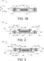
- FIG. 1B depicts a block diagram of a portion of the electronic device 100 having an auxiliary module 102 attached to a printed circuit assembly (PCA) 104.
- PCA printed circuit assembly
- FIGS. 1A-1B are described concurrently for ease of illustration. It should be understood that FIGS. 1A and 1B are not intended to illustrate specific shapes, dimensions, or other structural details accurately or to scale, and that implementations of the electronic device 100 may have different numbers and arrangements of the illustrated components and may also include other parts that are not illustrated.
- the electronic device 100 may be a computer (e.g., a server, a storage device), a networking device (e.g., a switch), or the like.
- the electronic device 100 is a server.
- the electronic device 100 includes an auxiliary module 102, a PCA 104, a main PCA 108, a support structure 106, and a cooling conduit 110.
- the auxiliary module 102 includes a circuit board 124, one or more electronic components 128 mounted on the circuit board 124, and electrical connectors 126 mounted on the circuit board 124.
- the one or more electronic components 128 are configured to provide auxiliary or support functionality for the primary components of the PCA 104, and the electrical connectors 126 are configured to electrical couple the electronic components 128 to the PCA 104 to facilitate the provisioning of the auxiliary/support functionality.
- the electronic components 128 include power conversion components (e.g., voltage regulators) and the electrical connectors 126 are configured to supply electrical power from the electronic components 128 to the PCA 104, and thus in this example the auxiliary module 102 may be referred to as a power conversion module.
- the electronic components 128 could be networking/communication components, hardware accelerators, or any other auxiliary components, and the electrical connectors 126 may be configured to convey data signals instead of (or in addition to) electrical power.
- the description below will focus for ease of understanding primarily on the example in which the auxiliary module 102 is a power conversion module, but the principles described below would apply mutatis mutandis to the other examples mentioned above in which other types of auxiliary modules 102 are used.
- the electronic device 100 may be electrically connected to a main power conversion module 112 via a first set of wires 114.
- the auxiliary module 102 of the electronic device 100 may be electrically connected to the main power conversion module 112 which in turn may be connected to a power source (not shown) of a rack (not shown) via a second set of wires 116.
- the main power conversion module 112 may include one or more electronic elements (not shown), which may step-down a high-voltage direct current (e.g., about 380V) to a relatively low voltage direct current (e.g., about 48V) and supply such low voltage direct current to the auxiliary module 102.
- the auxiliary module 102 e.g., an auxiliary power conversion module is connected to the main power conversion module 112 via the first set of wires 114 and to the PCA 104 via electrical connectors 126, 134.
- the auxiliary module 102 is configured to provide support e.g., electrical support to the PCA 104.
- the auxiliary module 102 may further step-down the relatively low voltage direct current received from the main power conversion module 112 to a low voltage direct current (e.g., about 12V to about 3.3V) and supply the low voltage direct current (electronic power) to the PCA 104 via the electrical connectors 126, 134.
- a low voltage direct current e.g., about 12V to about 3.3V
- the auxiliary module 102 includes an auxiliary PCA 118, a plurality of attachment elements 120 (see FIG. 1B ), a plurality of fasteners 158, and a cooling component 122. It may be noted herein that the plurality of attachment elements 120 are not shown in FIG. 1A for ease of illustration only, but they are shown in FIG. 1B .
- the auxiliary PCA 118 includes a circuit board 124, an electrical connector 126, and one or more electronic components 128. In some examples, the electrical connector 126 and the one or more electronic components 128 may be mounted on and coupled to the circuit board 124.
- the circuit board 124 may mechanically support the electrical connector 126 and the one or more electronic components 128, and electrically connect the one or more electronic components 128 to the electrical connector 126 using conductive pathways, or signal traces or the like (not shown) disposed in the circuit board 124.
- the one or more electronic components 128 e.g., voltage regulators, may be used to step-down the relatively low voltage direct current to the low voltage direct current.
- the electrical connector 126 may be power pins which may be configured to transmit the electronic power from the auxiliary PCA 118 to the PCA 104.
- the plurality of attachment elements 120 may be mounted on and coupled to one of the circuit board 124 or the cooling component 122 of the auxiliary PCA 118 to enable a plurality of fasteners 158 (see FIG. 1B ) to couple the auxiliary module 102 to the PCA 104.
- the attachment elements 120 are shown as coupled to the circuit board 124, but the attachment elements 120 could instead be coupled to the cooling component 122.
- the attachment elements 120 may be coupled to the circuit board 124 or the cooling component 122 via holes formed therein, threading, nuts, welding, brazing, adhesive, friction fitting, and/or any other fastening method.
- the fasteners 158 include threaded screws/bolts and the attachment elements 120 include standoffs (e.g., threaded hollow standoffs) to receive the fasteners 158, or threaded nuts to receive the fasteners 158.
- standoffs e.g., threaded hollow standoffs
- non-threaded members such as hollow standoffs, washers, etc.
- the attachment elements 120 may additionally enable the auxiliary PCA 118 to be coupled to the cooling component 122. It may be noted that the process of attaching the auxiliary module 102 to the PCA 104 and/or coupling the cooling component 122 to the auxiliary PCA 118 are discussed in greater details below.
- the cooling component 122 is a passive heat sink made of thermally conductive materials such as copper, aluminum, or the like.
- the cooling component 122 includes a first portion 122A having an engagement feature 123 e.g., a semi-circular shaped structure that complements with a complementary engagement feature 111 (e.g., an outer diameter) of the cooling conduit 110 and a second portion 122B having another engagement feature 125 (e.g., a substantially planar shaped structure) that complements with another complementary engagement feature 113 (e.g., an outer surface) of the one or more electronic components 128.
- the first portion 122A is disposed on the cooling conduit 110 and the second portion 122B is disposed on one or more electronic components 128 of the auxiliary PCA 118.
- the auxiliary module 102 may further include a first thermal interfacing material (TIM) 130 coupled to the first portion 122A of the cooling component 122 and one or more second TIMs 132 coupled to the second portion 122B of the cooling component 122.
- TIM first thermal interfacing material
- the first portion 122A may be thermally coupled to the one or more electronic components 128 via the first TIM 130
- the second portion 122B may be thermally coupled to the outer diameter of the cooling conduit 110 via the one or more second TIMs 132.
- the auxiliary module 102 may further include a biasing element (e.g., a captive screw assembly 184, as shown in FIGS.
- the biasing element may be a snap-fit assembly, a spring assembly, or the like without deviating from the scope of the present disclosure.
- the electrical connector 126 of the auxiliary PCA 118 may be coupled with a complementary electrical connector 134 of the PCA 104 to electrically connect the auxiliary PCA 118 to the PCA 104.
- the PCA 104 may be a separate integrated circuit package having a processor circuit board 136, a processing resource 138, a cold plate 140, a complementary electrical connector 134, and a secondary electrical connector 142.
- the processor circuit board 136 may be configured to mechanically support the processing resource 138, the complementary electrical connector 134, and the secondary electrical connector 142, and electrically connect the complementary electrical connector 134 to the processing resource 138 and the secondary electrical connector 142 using conductive pathways, or signal traces or the like (not shown) disposed in the processor circuit board 136.
- the processing resource 138 e.g., a central processing unit (CPU), graphical processing unit (GPU), System-on-Chip (Soc), or Application Specific Integrated Circuit (ASIC), etc.
- the complementary electrical connector 134 may be a socket or a sleeve configured to receive the electrical connector 126 of the auxiliary PCA 118, and thereby establish electrically connection by coupling the electrical connector 126 with the complementary electrical connector 134. Further, the complementary electrical connector 134 may transmit the electronic power received via the electrical connector 126 to the processing resource 138 of the PCA 104 and to the secondary electrical connector 142 of the main PCA 108. In certain examples, the secondary electrical connector 142 may transmit the electronic power to one or more electronic elements (not shown) of the main PCA 108.
- the cold plate 140 is thermally coupled to the processing resource 138 and configured to remove heat from the processing resource 138.
- the cold plate 140 includes a fluid inlet 140A coupled to the cooling conduit 110 to receive a cool fluid 148 and circulate the cool fluid 148 within an internal volume (not labeled) of the cold plate 140 to remove heat transferred from the processing resource 138 to the cold plate 140, and thereby generate a hot fluid 150.
- the cold plate 140 may further include a fluid outlet 140B connected to the internal volume of the cold plate 140 and configured to discharge the hot fluid 150 to a thermal management system (not shown) of the rack, for example.
- the support structure 106 is a mechanical component configured to provide mechanical support to the PCA 104 and to the circuit board 124 of the auxiliary module 102.
- the support structure 106 includes a base 144 and a plurality of supporting arms 146 protruding from the base 144 supporting the PCA 104.
- the base 144 may support the processor circuit board 136 and the plurality of supporting arms 146 may support the circuit board 124.
- each of the plurality of the supporting arms 146 protruding from the base 144 may be disposed between the circuit board 124 and the cooling component 122 of the auxiliary module 102.
- the support structure 106 is discussed in greater detail below.
- the main PCA 108 may be a motherboard of the electronic device 100, which may be configured to support the PCA 104 and the auxiliary PCA 118 via the PCA 104.
- the main PCA 108 includes a main circuit board 154, one or more electronic elements (not shown), and a tertiary electrical connector 152.
- the one or more electronic elements and the tertiary electrical connector 152 are mounted on and coupled to the main circuit board 154.
- the tertiary electrical connector 152 may receive the secondary electrical connector 142 of the main PCA 108 to electrically connect the processor circuit board 136 to the one or more electronic elements of the main PCA 108.
- the cooling conduit 110 is configured to receive the cool fluid 148 from the thermal management system and supply the cool fluid 148 to the cold plate 140 of the PCA 104.
- the cooling conduit 110 has a circular shaped structure which complements the semi-circular shaped structure of the first portion 122A of the cooling component 122.
- each of the plurality of supporting arms 146 includes an aperture 190 (e.g., slot) and the cooling component 122 includes a plurality of openings 170.
- the plurality of attachment elements 120 is disposed on and coupled to the circuit board 124. In such examples, when the circuit board 124 having the plurality of attachment elements 120 is mounted to the plurality of supporting arms 146, each attachment element of the plurality of attachment elements 120 protrudes through a corresponding aperture 190 in the supporting arms 146.
- each opening of the plurality of openings 170 in the cooling component 122 is aligned with the corresponding attachment element (e.g., standoff or threaded hollow standoff) of the plurality of attachment elements 120.
- each of the plurality of supporting arms 146 is disposed between the cooling component 122 and the circuit board 124.
- the plurality of fasteners 158 may then be inserted through the plurality of openings 170 and into the plurality of attachment elements 120 to attach the cooling component 122 to the circuit board 124 of the auxiliary PCA 118 and to the plurality of supporting arms 146. That is, in the example of FIG.
- the supporting arms 146 are sandwiched between the cooling component 122 and the circuit board 124, with the attachment elements 120 retaining the supporting arms 146 in this position.
- the electrical connector 126 (see FIG. 1A ) may be coupled to the complementary electrical connector 134 (see FIG. 1A ) to establish electrical connection between the auxiliary module 102 and the PCA 104, and the plurality of fasteners 158 may engage with the plurality of attachment elements 120 to attach the auxiliary module 102 to the plurality of supporting arms 146, and the auxiliary PCA 118 to the cooling component 122.
- the first portion 122A of the cooling component 122 is thermally coupled to the cooling conduit 110.
- the second portion 122B of the cooling component 122 is thermally coupled to the one or more electronic components 128.
- the auxiliary module 102 in the attached state of the auxiliary module 102 to the plurality of supporting arms 146 and the coupled state of the electrical connector 126 with the complementary electrical connector 134, the auxiliary module 102 is movable in one or more degrees of freedom of motion relative to the plurality of supporting arms 146 to overcome issues related to tolerance stack up in the cooling conduit 110.
- the auxiliary module 102 can be translated (within defined limits) relative to the support arms 146 along one or more directions (e.g., a longitudinal direction 10, a lateral direction 20, and/or a vertical direction 30).
- the auxiliary module 102 is not only movable in translation but may also be rotatable (within defined limits) about one more axes of rotation, such as about an axis parallel to the lateral direction 20, an axis parallel to the vertical direction 30, and/or an axis parallel to the longitudinal direction 10.
- the auxiliary module 102 is rotatable about an axis 121 which is parallel to the vertical direction 30, and such rotation may also be referred to herein as motion or rotation in a radial direction.
- the translational and/or rotational motion of the auxiliary module 102 relative to the supporting arms may be facilitated in part by the configuration of the electrical interface (e.g., the electrical connectors 134 are configured to allow motion of the electrical connectors 126 while connected) and in part by the apertures 158 and/or the openings 170 being oversized in at least one dimension thereof to allow for movement of the attachment members 120 relative to the support arms and/or to allow for movement of the fasteners 158 relative to the cooling component 122.
- a spacing between the cooling component 122 and the circuit board 124 may exceed the thickness of the supporting arms 146, which may facilitate motion along the vertical direction 30 and/or rotation about axes parallel to the longitudinal and/or lateral dimensions 10, 20.
- the spacing between the cooling component 122 and the circuit board 124 may be controlled by the attachment members 120 and fasteners.
- the auxiliary module 102 as a whole may be movable relative to the support arms 146, in some examples the circuit board 124 may be fixed relative to the cooling component 122 once assembled. However, during various stages of assembly the circuit board 124 and the cooing component 122 may move relative to one another to facilitate the assembly. For example, the above described oversizing of the openings 170 and/or apertures 190 may facilitate such motion of the circuit board 124 relative to the cooling component 122 during assembly.
- FIG. 1B the circuit board 124 and the cooling component 122 are both directly coupled to the support arms 146 and to one another via a single set of fasteners 158 and attachment members 120.
- the connections between the components of the auxiliary module 102 may differ.
- FIG. 2 illustrates an example in which the circuit board is coupled directly to the support arms and to the cooling component using two different sets of fasteners and attachment members, whereas the cooling component is not directly connected to the support arms (the cooling component is instead indirectly connected to the support arms via the circuit board).
- FIG. 2 illustrates an example in which the circuit board is coupled directly to the support arms and to the cooling component using two different sets of fasteners and attachment members, whereas the cooling component is not directly connected to the support arms (the cooling component is instead indirectly connected to the support arms via the circuit board).
- FIG. 2 illustrates an example in which the circuit board is coupled directly to the support arms and to the cooling component using two different sets of fasteners and attachment members, whereas the cooling component is not directly connected to the support arms (the cooling component is
- cooling component is coupled directly to the support arms and to the circuit board using two different sets of fasteners and attachment members, whereas the circuit board is not directly connected to the support arms (the circuit board is instead indirectly connected to the support arms via the cooling component).
- FIG. 2 depicts a block diagram of an auxiliary module 202 attached to a PCA 204 of an electronic device 200.
- each of a plurality of supporting arms 246 of a support structure 206, protruding from the PCA 204 includes an aperture 290 and a cooling component 222 includes a plurality of openings 270.
- a plurality of attachment elements 220 having a first set of attachment elements 220A and a second set of attachment elements 220B is disposed on and coupled to the circuit board 224. In such examples, when the circuit board 224 having the plurality of attachment elements 220 is mounted to the plurality of supporting arms 246, the first set of attachment elements 220A protrudes through a corresponding aperture 290.
- the auxiliary module 202 may further include a plurality of fasteners 258 having a first set of fasteners 258A and a second set of fasteners 258B.
- Each of the first set of fasteners 258A may extend into the first set of attachment elements 220A to attach the auxiliary module 202 to the PCA 204 (or in particular, attach an auxiliary PCA 218 to the plurality of supporting arms 246).
- the auxiliary module 202 may be movable along one or more directions relative to the plurality of supporting arms 246 to overcome issues related to tolerance stack up in the cooling loop (not shown). More specially, the circuit board 224 is movable relative to the support arms 246. Similarly, each of the second set of fasteners 258B may extend through the plurality of openings 270 in the cooling component 222 to attach the cooling component 222 to the circuit board 228 of the auxiliary PCA 218. In the example of FIG. 2 , the cooling component 222 is fixed relative to the circuit board 224 once assembled. However, during various stages of assembly the circuit board 224 and the cooing component 222 may move relative to one another to facilitate the assembly.
- FIG. 3 depicts a block diagram of an auxiliary module 302 attached to a PCA 304 of an electronic device 300.
- each of a plurality of supporting arms 346 of a support structure 306, protruding from the PCA 304 includes an aperture 390 and a cooling component 322 includes a plurality of openings 370 including a first set of openings 370A and a second set of openings 370B.
- a plurality of attachment elements 320 includes a first set of attachment elements 320A and a second set of attachment elements 320B. The first set of attachment elements 320A is disposed on and coupled to the cooling component 322 and the second set of attachment elements 320B is disposed on and coupled to the circuit board 324.
- the auxiliary module 302 may further include a plurality of fasteners 358 having a first set of fasteners 358A and a second set of fasteners 358B.
- Each of the first set of fasteners 358A may extend through the first set of openings 370A and into the first set of attachment elements 320A to attach the auxiliary module 302 to the PCA 304 (or in particular, attach an auxiliary PCA 318 to the plurality of supporting arms 346).
- the auxiliary module 302 may be movable along one or more directions relative to the plurality of supporting arms 346 to overcome issues related to tolerance stack up in the cooling loop (not shown). More specially, the cooling component 322 is movable relative to the support arms 346.
- each of the second set of fasteners 358B may extend through the second set of openings 370B in the cooling component 322 to attach the cooling component 322 to the circuit board 228 of the auxiliary PCA 218.
- the cooling component 322 is fixed relative to the circuit board 324 once assembled. However, during various stages of assembly the circuit board 324 and the cooing component 322 may move relative to one another to facilitate the assembly.
- FIG. 4A depicts a perspective top view of a cooling component 122 of an auxiliary module 102, which is one example configuration of the cooling component of FIGS. 1A-1B .
- FIG. 4B depicts a perspective bottom view of the cooling component 122 of FIG. 4A .
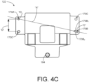
- FIG. 4C depicts a perspective bottom view of the cooling component 122 of FIG. 4A .
- FIGS. 4A-4C are described concurrently for ease of illustration.
- the cooling component 122 includes a first portion 122A and a second portion 122B extending from the first portion 122A. Further, the cooling component includes a first flange 160 and a second flange 162 extending from opposite ends of the second portion 122B.
- the first portion 122A has an engagement feature 123 that complements with a complementary engagement feature 111 (See, FIG. 1A ) of the cooling conduit 110.
- the engagement feature 123 forms a track or groove having a similar profile in cross-section as the cooling conduit 110, and the cooling conduit 110 may be disposed in this track or groove such that the engagement feature 123 (See, FIG.
- the cooling conduit 110 is cylindrical in shape and the complementary engagement feature 111 thereof may be a portion (e.g., the top half) of the outer diameter of the cooling conduit 110 along a particular length thereof, and in these examples the engagement feature 123 may comprise a curved engagement surface which has an arched or semi-circular shape in cross-section so as to receive and engage with the outer diameter of the cooling conduit 110 (either direction, or via a TIM 130).
- the first portion 122A further includes a biasing element (e.g., a captive screw assembly 184).
- the first portion 122A includes a captive screw hole 164 to allow mounting of the captive screw assembly 184 on to the cooling component 122.
- the auxiliary module 102 includes a first TIM 130 coupled to the first portion 122A.
- the first TIM 130 is coupled to a portion of an inner surface of the first portion 122A of the cooling component 122 which may be thermally coupled to the circular shaped cooling conduit 110.
- the first portion 122A is configured to thermally couple with the cooling conduit 110 via the first TIM 130.
- the second portion 122B has a generally planar shape that complements an outer surface of one or more electronic components 128 (see FIG. 1A ).
- the auxiliary module 102 may further include one or more second thermal interface materials (TIMs)132 coupled to the second portion 122B.
- TIMs second thermal interface materials
- the one or more second TIMs132 is coupled to another portion of the inner surface of the second portion 122B which may be thermally coupled to the one or more electronic components 128.
- the second portion 122B is configured to thermally couple with the one or more electronic components 128, directly or via the one or more second TIMs 132.
- the cooling component 122 further includes a plurality of openings 170.
- the plurality of openings 170 includes a first opening 170A, a second opening 170B, and a pair of third openings 170C.
- the first opening 170A and one opening among the pair of third openings 170C are formed in the first flange 160.
- the second opening 170B and another opening among the pair of third openings 170C are formed in the second flange 162.
- the first opening 170A and the second opening 170B are formed on diagonally opposite sides of the first flange 160 and the second flange 162.
- the pair of third openings 170C are formed on another diagonally opposite sides of the first flange 160 and the second flange 162.
- the second opening 170B may be an elongated slot having long edges 170B 1 and 170B 2 that extends parallel to an axis "A" extending between centers "C" of the first opening 170A and the second opening 170B.
- each of the first opening 170A and one opening among the pair of third openings 170C and the second opening 170B and the other opening among the pair of third openings 170C are disposed spaced apart from each other by a distance "D".
- the first opening 170A has a diameter which is smaller than the diameter of each of the second opening 170B and the third pair of openings 170C.
- the pair of third openings 170C has a diameter smaller than the diameter of the second opening 170B.
- the second portion 122B further includes protrusions 172.
- a first protrusion 172A is located between the first opening 170A and one opening among the pair of third openings 170C and coupled to the first flange 160.
- a second protrusion 172B is located between the second opening 170B and other opening among the pair of third openings 170C and coupled to the second flange 162.
- Each of the protrusions 172 is configured to extend via a notch (as shown in FIG. 9 ) formed in the supporting arms 146 and contact the circuit board 124 to limit over constraining of each of the plurality of fasteners 158 while coupling the cooling component 122 and the auxiliary PCA 118 to each other.
- FIG. 5 depicts a perspective view of an auxiliary PCA 118 of an auxiliary module 102 of FIGS. 1A-1B .
- the auxiliary PCA 118 includes a circuit board 124, electrical connectors 126, one or more electronic components 128, one or more electronic elements 166, and one or more holes 168.
- the circuit board 124 may be configured to mechanically support the electrical connectors 126, the one or more electronic components 128, and the one or more electronic elements 166.
- each of the electrical connectors 126, the one or more electronic components 128, and the one or more electronic elements 166 are disposed on and coupled to the circuit board 124.
- one of the electronic elements 166 may be electrically connected to the first pair of wires 114 (see FIG.
- the one or more electronic components 128 may be further electrically connected to the electrical connectors 126.
- the electrical connector 126 may be a power pin and each of the electronic components 128 may be a voltage regulator.
- the one or more electronic components 128 may step-down the relatively low voltage direct current to a low voltage direct current and transmit the low voltage direct current to the electrical connectors 126.
- the one or more electronic components 128 may generate heat, which needs to be transferred out of the auxiliary PCA 118 to prevent component failure due to overheating condition and obtaining optimum performance from the one or more electronic components 128
- the one or more electronic components 128 and the one or more electronic elements 166 may be housed inside the second portion 122B of the cooling component 122.
- the second portion 122B may be thermally coupled to the one or more electronic components 128 via the one or more second TIMs 132.
- the one or more holes 168 may be configured to receive a corresponding attachment element among the plurality of attachment elements 120 and couple the received attachment element 120 to the circuit board 124 of the auxiliary PCA 118.
- the holes 168 may comprise threading which engages with threading of the attachment elements 120 to secure the attachment element 120 to the circuit board 124.
- the attachment element 120 may be inserted into the holes 168 and coupled thereto via friction fitting, adhesive, welding, or any other attachment method.
- FIG. 6 depicts a perspective view of one of a plurality of attachment elements 120 of an auxiliary module 102 of FIGS. 1A-1B .
- the attachment element 120 may be a standoff having a cylindrical portion 174, a coupler portion 178, and a hole 176 having threads (not shown) defined there through the cylindrical portion 174 and the coupler portion 178 for receiving a corresponding fastener among the plurality of fasteners 158 having counter threads (not shown).
- the coupler portion 178 is configured to protrude into the corresponding hole among the plurality of holes 168 in the circuit board 124 to couple the attachment element 120 to the auxiliary PCA 118.
- FIG. 7 depicts a perspective view of one fastener among the plurality of fasteners 158 of an auxiliary module 102 of FIGS. 1A-1B .
- the fastener 158 may include a head portion 180 and a body portion 182 having counter threads (not shown).
- the fastener 158 may extend in one of a corresponding opening 170 of the cooling component 122 or the attachment element 120 to attach the auxiliary module 102 to the supporting arms 146 and auxiliary PCA 118 to the cooling component 122.
- FIG. 8 depicts a perspective view of a biasing element, e.g., a captive screw assembly 184 of the cooling component 122.
- the cooling component 122 may include other types of biasing element such as a snap-fit assembly, a spring assembly, or the like without deviating from the scope of the present disclosure.
- the captive screw assembly 184 is a special type of screw assembly that may remain freely inside an opening of an object without getting lost from the object, and at the same time it may be selectively fastened or unfastened to lock to or unlock from another object.
- the captive screw assembly 184 includes a captive screw 186 and a coupler object 188.
- the coupler object 188 may be disposed on the captive screw hole 164 formed in the first portion 122A of the cooling component 122.
- the captive screw 186 may remain freely inside an opening (not labeled) of the coupler object 188 without getting lost from the coupler object 188 and may be fastened to push the first portion 122A on the cooling conduit 110 to thermally couple the first portion 122A to the cooling conduit 110.
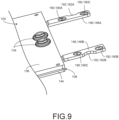
- FIG. 9 depicts a perspective view of a portion of the PCA 104 and the support structure 106 of FIGS. 1A-1B .
- the PCA 104 includes a processor circuit board 136 and complementary electrical connectors 134. It may be noted that a processing resource 138, a cold plate 140, and a secondary electrical connector 142 are not visible in the view shown in FIG. 9 and those components are shown in the example of FIG. 1A .
- the complementary electrical connectors 134 e.g., sockets or sleeves are mounted on and coupled to the processor circuit board 136.
- the processor circuit board 136 may include one of conductive pathways, or signal traces or the like (not shown) for connecting each of the complementary electrical connectors 134 to the processing resource 138 and the secondary electrical connector 142.
- the support structure 106 is a mechanical component having a base 144 and a plurality of supporting arms 146 including a first supporting arm 146A and a second supporting arm 146B, each protruding from the base 144.
- the base 144 supports the processor circuit board 136 and the plurality of supporting arms 146 supports the circuit board 124 of the auxiliary PCA 118.
- each supporting arm of the plurality of supporting arms 146 includes apertures 190, e.g., the apertures 190 includes a first aperture 190A, a second aperture 190B, and a pair of third apertures 190C, and a notch 192, e.g., a first notch 192A and a second notch 192B.
- the first supporting arm 146A includes a first aperture 190A and one aperture among the pair of third apertures 190C.
- the second supporting arm 146B includes a second aperture 190B and another aperture among the pair of third apertures 190C.
- the first aperture 190A and the second aperture 190B are formed on diagonally opposite sides of the first supporting arm 146A and the second supporting arm 146B.
- the pair of third apertures 190C are formed on another diagonally opposite sides of the first supporting arm 146A and the second supporting arm 146B.
- each of the first aperture 190A, the second aperture 190B, and the pair of third apertures 190C may be a slot (oversized slot) and has a width greater than a diameter of the corresponding attachment element among the plurality of attachment elements 120 to allow the cooling component 122 and the auxiliary PCA 118 (e.g., the auxiliary module 102) to move as an unit along one or more directions relative to the plurality of supporting arms 146 to align the first portion 122A of the cooling component 122 on the cooling conduit 110 and thermally couple the first portion 122A to the cooling conduit 110 and the second portion 122B to the one or more electronic components 128.
- the auxiliary PCA 118 e.g., the auxiliary module 102
- the first notch 192A is formed in the first supporting arm 146A between the first aperture 190A and one aperture among the pair of third apertures 190C.
- the second notch 192B is formed in the second supporting arm 146B between the other aperture among the pair of third apertures 190C and the second aperture 190B.
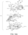
- FIG. 10A depicts an exploded perspective view of the electronic device 100.
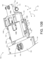
- FIG. 10B depicts an assembled perspective view of the electronic device 100.
- FIGS. 10A-10B are described concurrently for ease of illustration.
- the electronic device 100 shown in the example of FIG. 10A includes an auxiliary module 102, a PCA 104, and a support structure 106.
- the auxiliary module 102 includes an auxiliary PCA 118, a plurality of attachment elements 120, a cooling component 122, a plurality of fasteners 158, and a captive screw assembly 184.
- the auxiliary PCA 118 includes a circuit board 124, electrical connectors 126 e.g., power pins, and one or more electronic components 128.
- the electrical connectors 126 and the one or more electronic components are coupled to the circuit board 124.
- each of the plurality of attachments elements is a standoff including a recess or hole therein and threads defined there through the hole.
- the cooling component 122 includes a first portion 122A and a second portion 122B.
- the captive screw assembly 184 is coupled to the first portion 122A.
- the second portion 122B includes a plurality of openings 170, e.g., a first opening 170A, a second opening 170B, and a pair of third openings 170C.
- the second portion 122B further includes protrusions 172.
- the plurality of fasteners 158 includes a first fastener 158A, a second fastener 158B, and a pair of third fasteners 158C. In the example of FIG.
- the PCA 104 includes a processor circuit board 136 and complementary electrical connectors 134 e.g., sockets coupled to the processor circuit board 136.
- the support structure 106 includes a base 144 and a plurality of supporting arms 146, e.g., a first supporting arm 146A and a second supporting arm 146B. In one or more examples, each of the plurality of supporting arm 146 protrudes from the base 144.
- the base 144 supports the processor circuit board 136.
- Each of the plurality of supporting arms 146 includes apertures 190, e.g., a first aperture 190A, a second aperture 190B, and a pair of third apertures 190C.
- the process begins by positioning the auxiliary PCA 118 below the PCA 104 and the support structure 106 such that the electrical connectors 126 are aligned to the complementary electrical connectors 134, the first attachment element 120A is aligned with the first aperture 190A, the second attachment element 120B is aligned with the second aperture 190B, the pair of third attachment elements 120C are aligned with the pair of third apertures 190C.
- the auxiliary PCA 118 is then electrically coupled to the PCA 104 by mating the electrical connectors 126 with the complementary electrical connectors 134.
- the attachment elements 120 may also be caused to extend through the apertures 190 in the supporting arms 146.
- the cooling component 122 is positioned over the auxiliary PCA 118 and the cooling conduit 110 such that the first portion 122A is disposed on the cooling conduit 110 and a second portion 122B is disposed on one or more electronic components 128.
- the plurality of supporting arms 146 are located between the auxiliary PCA 119 and the cooling component 122, and the openings 170 may be roughly aligned with corresponding apertures 190 and the attachment elements 120 disposed therein (e.g., first opening 170A is aligned with the first aperture 190A, the second opening 170B is aligned with the second aperture 190B, and the pair of third openings 170C are aligned with the pair of third apertures 190C).
- each protrusion 172 in the cooling component 122 extends via the notch 192 in the corresponding supporting arm146 and contact the circuit board 124.
- the cooling component 122 may then be engaged with and coupled to the cooling conduit 110, which fixes the location of the cooling component 122.
- the cooling component 122 might not be perfectly aligned with the circuit board 124 because the location and orientation of the cooling conduit 110 relative to the PCA 104 may vary slightly from the nominal designed location due to the tolerance stack up.
- the circuit board 124 can be moved relative to the supporting arms 124 to bring it into alignment with the cooling component 120 because the apertures 190 are oversized relative to the attachment members.
- the fasteners 158 may be inserted through the openings 170 into the attachment members 120 and fastened, which will hold the circuit board 124 in the aligned position.
- the fastening of the to the plurality of attachment elements 120 may proceed as follows: i) the circuit board 124 is moved along the XY directions (longitudinal direction 10 and lateral direction 20) until the first opening 170A aligns with the first attachment element 120A and then the first fastener 158A may be engaged with the first attachment element 120A and fastened, which constrains the XY position of circuit board 124 relative to the cooling component 122, ii) the circuit board 122 may be rotated about a vertical axis (e.g., pivoted about the first fastener 158A) until the second opening 170B is aligned with the second attachment element 120B and then the second fastener 158B may be inserted through the second opening 170B into the second attachment element 120 and fastened, which constrains the orientation of the circuit board
- the protrusion 172 contacting the circuit board 124 may limit over constraining of each of the plurality of fasteners 158 while coupling the cooling component 122 and the auxiliary PCA 118 to each other.
- the captive screw assembly 184 is further fastened to push the semi-circular shaped structure formed in the first portion 122A onto the outer diameter of the cooling conduit 110 to thermally couple the cooling component 122 to the cooling conduit 110.
- the first portion 122A is thermally coupled with the cooling conduit 110 via the first TIM 130 coupled to the first portion 122A.
- the second portion 122B is thermally coupled with the one or more electronic components 128 via the second TIMs132 coupled to the second portion 122B.
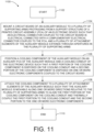
- FIG. 11 depicts a flowchart depicting a method 1100 of assembling an auxiliary module to a PCA of an electronic device. It may be noted herein that the method 1100 is described in conjunction with FIGS. 1A-1B , 4A-4C , 5-9 , and 10A-10B for example. The method 1100 starts at block 1102 and continues to block 1004.
- the method 1100 includes mounting a circuit board of an auxiliary module to a plurality of supporting arms protruding from a support structure of a printed circuit assembly (PCA) of an electronic device such that an electrical connector coupled to the circuit board is electrical connected with a complementary electrical connector coupled to the PCA, and a plurality of attachment elements of the auxiliary module extends through apertures (slots) in the plurality of supporting arms.
- PCA printed circuit assembly
- the method 1100 continues to block 1106.
- the method 1100 includes positioning a cooling component of the auxiliary module on an auxiliary PCA of the auxiliary module and a cooling conduit of the electronic device such that a first portion of the cooling component is disposed on the cooling conduit and a second portion of the cooling component is disposed on one or more electronic components coupled to the circuit board.
- the method 1100 continues to block 1108.
- the method 1100 includes attaching the cooling component to a plurality of attachment elements of the auxiliary module such that the auxiliary module is movable along one or more directions relative to the plurality of supporting arms to align the first portion of the cooling component on the cooling conduit and thermally couple the first portion to the cooling conduit and the second portion to the one or more electronic components.
- a biasing element e.g., a captive screw assembly disposed on the first portion is first fastened to partially install the cooling component on the cooling conduit.
- first fastener among the plurality of fasteners may be extended through a first opening of the cooling component and the corresponding attachment element and tightened to fix the cooling component onto the auxiliary PCA and provide the accurate XY tolerance control to link the two parts together.
- a second fastener among the plurality of fasteners may be extended through a second opening (e.g., elongated slot) of the cooling component and the corresponding standoff and tightened to restrain rotation of the auxiliary module about the Z direction and thereby completing the alignment of the auxiliary module.
- a third pair of fasteners among the plurality of fasteners may be extended through a pair of third openings and served to form a robust connection between the cooling component and the auxiliary PCA.
- the captive fastener assembly may be further tightened to push the half circle channel of the cooling component onto the cooling conduit to fully install the cooling component on the cooling conduit.
- the first portion of the cooling component is thermally coupled with the cooling conduit via a first thermal interface material coupled to the first portion of the cooling component.
- the second portion of the cooling component is thermally coupled with the one or more electronic components via one or more second thermal interface materials coupled to the second portion of the cooling component.
- an auxiliary module of the present disclosure may provide the benefits such as a) cooling component being the passive heat sink does not add a leak risk but provides high thermal performance results with cooling conduit contact, b) auxiliary module with poor reliability (relatively) parts can be swapped and not discard the extremely expensive processor PCA or the main PCA, c) replaceable auxiliary module will reduce service time/cost and prevent accidental damage of other internal components of the electronic device, d) self-align capability of the cooling component on the cooling conduit may allow for the thin gap pads to be disposed therebetween the cooling component and the cooling conduit which saves money and results in the best thermal performance, and e) not integrating the power on the processor PCA or the main PCA may prevent issues with critical signal routing and integrity performance.
Landscapes
- Engineering & Computer Science (AREA)
- Microelectronics & Electronic Packaging (AREA)
- Physics & Mathematics (AREA)
- Thermal Sciences (AREA)
- Theoretical Computer Science (AREA)
- General Engineering & Computer Science (AREA)
- Human Computer Interaction (AREA)
- General Physics & Mathematics (AREA)
- Computer Hardware Design (AREA)
- Power Engineering (AREA)
- Cooling Or The Like Of Electrical Apparatus (AREA)
- Coupling Device And Connection With Printed Circuit (AREA)
Abstract
Auxiliary module includes attachment elements, cooling component, and auxiliary PCA having a circuit board, an electrical connector, and electronic components. The attachment elements are configured to attach the auxiliary module to supporting arms protruding from the PCA such that the electrical connector is coupled to a complementary electrical connector of the PCA, and the attachment elements extend through apertures in the supporting arms. The cooling component is attached to the auxiliary PCA and includes a first portion thermally coupled to cooling conduit in an installed state of the auxiliary module and a second portion thermally coupled to the electronic components in an attached state of the cooling component to the auxiliary PCA. In an attached state of the auxiliary module to the supporting arms and a coupled state of the electrical connector with the complementary electrical connector, the auxiliary module is movable along multiple directions relative to the supporting arms.
Description
- An electronic device, such as a computing device, a network device, or the like may include one or more printed circuit assemblies (PCAs) which include electronic components. The electronic components may include primary electronic components such as processing resources (e.g., a central processing unit (CPU), graphical processing unit (GPU), System-on-Chip (Soc), Application Specific Integrated Circuit (ASIC), etc.), and secondary or auxiliary electronic components (e.g., voltage regulators, network interfaces, etc.) that support the operations of the primary electronic components and/or provide supplemental or auxiliary functions for the electronic device. In many electronic devices, one or more primary electronic components and one or more auxiliary electronic components may be part of the same PCA and are mounted to the same circuit board of the PCA. This is often the case, for example, with auxiliary electronic components such as voltage regulators or other power conversion components that supply electronic power to the processing resources. For example, typically electronic devices may include a primary PCA (e.g., a motherboard or a main PCA) having a circuit board, one or more processors (primary electronic components), and one or more voltage regulators (auxiliary electronic components) for supplying the electronic power to the processors, where the processors and the voltage regulators are disposed on the circuit board.
- During operation of the electronic device, each of the auxiliary electronic components may generate heat. If such heat is not dissipated, temperatures of the auxiliary electronic components may exceed their thermal specifications, thus resulting in degraded performance, reliability, and life expectancy of the individual electronic components and/or the electronic device, as a whole. To minimize such adverse effects of the heat, the electronic device may include a thermal management device to remove heat. In some electronic devices, liquid cooling is used, in which case the thermal management device may include a cooling device (e.g., a cold plate) that is disposed in thermal contact with the electronic components to remove the heat away from such electronic components.
- Various examples will be described below with reference to the following figures.
-
FIG. 1A illustrates a block diagram of an electronic device having an auxiliary module, a printed circuit assembly (PCA), a main PCA, a support structure, and a cooling conduit according to an example of the present disclosure. -
FIG. 1B illustrates a block diagram of a portion of the electronic device having the auxiliary module attached to the PCA according to an example of the present disclosure. -
FIG. 2 illustrates a block diagram of an auxiliary module attached to a PCA according to another example of the present disclosure. -
FIG. 3 illustrates a block diagram of an auxiliary module attached to a PCA according to yet another example of the present disclosure. -
FIG. 4A illustrates a perspective top view of a cooling component of the auxiliary module ofFIGS. 1A-1B according to an example of the present disclosure. -
FIG. 4B illustrates a perspective bottom view of the cooling component ofFIG. 4A according to an example of the present disclosure. -
FIG. 4C illustrates a top view of the cooling component ofFIG. 4A according to an example of the present disclosure. -
FIG. 5 illustrates a perspective view of an auxiliary PCA of the auxiliary module ofFIGS. 1A-1B according to an example of the present disclosure. -
FIG. 6 illustrates a perspective view of an attachment element of the auxiliary module ofFIGS. 1A-1B according to an example of the present disclosure. -
FIG. 7 illustrates a perspective view of a fastener of the auxiliary module ofFIGS. 1A-1B according to an example of the present disclosure. -
FIG. 8 illustrates a perspective view of a biasing element of the auxiliary module ofFIGS. 1A-1B according to an example of the present disclosure. -
FIG. 9 illustrates a perspective view of a portion of the PCA ofFIGS. 1A-1B according to an example of the present disclosure. -
FIG. 10A illustrates an exploded perspective view of a portion of an electronic device ofFIGS. 1A-1B according to an example of the present disclosure. -
FIG. 10B illustrates an assembled perspective view of the portion of the electronic device ofFIG. 10A according to an example of the present disclosure. -
FIG. 11 is a flowchart depicting a method of assembling an auxiliary module to a PCA of an electronic device according to one example of the present disclosure. - The following detailed description refers to the accompanying drawings. For purposes of explanation, certain examples are described with reference to the components illustrated in
FIGS. 1-11 . The functionality of the illustrated components may overlap, however, and may be present in a fewer or greater number of elements and components. Moreover, the disclosed examples may be implemented in various environments and are not limited to the illustrated examples. Wherever possible, the same reference numbers are used in the drawings and the following description to refer to the same or similar parts. It is to be expressly understood, however, that the drawings are for the purpose of illustration and description only. While several examples are described in this document, modifications, adaptations, and other implementations are possible. Accordingly, the following detailed description does not limit the disclosed examples. Instead, the proper scope of the disclosed examples may be defined by the appended claims. - As noted above, in many electronic devices, one or more of primary electronic components (e.g., the processing resources) and one or more auxiliary electronic components (e.g., voltage regulators) are imbedded directly into the same circuit board of a primary PCA (e.g., a motherboard or a main PCA) of the electronic device. One potential drawback of this implementation is that, if one of the electronic components of the primary PCA fails, it may be difficult to repair or replace the failed electronic component without risking collateral damage to the primary PCA. Because of the risk of collateral damage, specialized tools and procedures may be needed and much care may need to be taken during the repair/replacement, and this may increase the costs of the repair/replacement. Moreover, even when care is taken, such collateral damage may still sometimes occur, which may result in the entire primary PCA needing to be replaced (which can be very expensive). Thus, repairs or replacements of the failed electronic components may be very difficult and expensive, even if the electronic components being repaired/replaced is itself relatively inexpensive. Such costly repairs and/or primary PCA replacements often occur mainly due to the failure of the auxiliary electronic components, such as a voltage regulator, as these auxiliary electronic components may be prone to failing sooner than other electronic components of the primary PCA.
- Another potential drawback of the above-described implementation with the primary electronic component (e.g., processing resources) and the auxiliary electronic components (e.g., voltage regulators) being co-located on the same circuit board is that, in some cases, the signal wiring for communicating signals to and from the processing resources and the power wiring for providing power from the voltage regulators to the processing resources may compete for the same limited space within the available layers of the circuit board, and sometimes there may be insufficient space for both. This difficulty is becoming more common as electronic components become more complicated and consume more power. Moreover, providing more layers in the circuit board to accommodate all the signaling and power needs may not always be feasible, as it may increase the circuit board thickness, increase cost, and/or reduce signal integrity.
- Accordingly, one way to address the above-described issues is to provide some of the auxiliary electronic components as part of a separate, replaceable, PCA instead of imbedding them in the primary PCA having the primary electronic components. In particular, a replaceable power conversion module having a separate circuit board and auxiliary electronic components (e.g., power conversion components) imbedded in such circuit board may be used instead of imbedding the power conversion components directly into the primary PCA. Because the auxiliary electronic components such as the power conversion components are provided as part of a separate replaceable power conversion module, if those components fail they may be relatively easily replaced by replacing the replaceable power conversion module as a unit without the risk of damaging other parts of the primary PCA and without requiring replacement of the entire primary PCA, thus mitigating the difficulties noted above related to the replacement and service costs and serviceability problems of the traditional implementation.
- However, designing and manufacturing electronic devices in which the auxiliary electronic components, such as power conversion components which are provided as part of a separate replaceable power conversion module (or an auxiliary module), may sometimes be a challenge because of space constraints and diverse geometry of the auxiliary module. Specifically, in previous approaches in which some auxiliary electronic components, such as power conversion components (e.g., voltage regulators) were provided adjacent to processing resources on the same circuit board, the auxiliary electronic components could be cooled by the same cooling component (e.g., cold plate) as the processing resource (e.g., by extending the cold plate slightly beyond the processing resource to also cover the voltage regulator), but if the auxiliary electronic component is provided as part of a separate auxiliary module, it may not be feasible to use the same cooling component to cool the auxiliary electronic components and the primary electronic components. But providing a separate cooling component to cool the auxiliary module (e.g., replaceable power conversion module) may also be difficult because, in view of the auxiliary module being separate from the primary PCA, it may not be feasible to control the location and orientation of the auxiliary module relative to other parts of the electronic device with the degree of precision needed for good cooling performance. In particular, the manufacturing tolerances of the cooling component, the auxiliary module, the connections between the auxiliary module and the other PCAs, and cooling loop structures, which are used for providing cooling to the auxiliary module, may all combine (stack up) in such a way that the cooling component and the cooling loop structures may sometimes be slightly out of alignment with one another, resulting in no contact or intermittent contact therebetween and thus poor thermal performance. One way to mitigate this issue would be to tighten tolerances sufficiently to ensure adequate contact between the cooling component and the cooling loop structures, but doing this may greatly increase manufacturing costs and thus may not be feasible in some circumstances. Hence, a challenge in using the separate auxiliary module (e.g., replaceable power conversion module) would be to provide the cooling component for cooling the auxiliary module economically and efficiently considering its location, geometries, and variations in the cooling loop structures tolerance.
- A technical solution to the aforementioned problems includes providing an auxiliary module (e.g., an auxiliary power conversion module) including a cooling component and an auxiliary PCA, which is separate from another PCA (e.g., a processor PCA) which carries the processing resources, where the auxiliary module is configured to be electrically connected and mechanically attached to the processor PCA in such a manner that the auxiliary module can move relative to the processor PCA. Specifically, in some examples, the cooling component and the auxiliary PCA are configured to be coupled together and attached to supporting arms that protrude laterally from the processor PCA, while an electrical connector of the auxiliary PCA is configured to electrically connect with a complementary electrical connector of the processor PCA, wherein these mechanical and electrical connections are such that they allow the auxiliary PCA and the cooling component to move together as a unit along multiple directions. This ability to move the auxiliary module (i.e., the auxiliary PCA and the cooling component) while it is electrically and mechanically connected to the processor PCA may allow the location and orientation of the cooling component to be adjusted as needed to align with and mount to a cooling conduit (or a cooling loop structure) of an electronic device with good thermal contact therebetween, thereby overcoming issues related to tolerance stack up of the traditional implementation. In some examples, the cooling component may include engagement features for interfacing with the cooling conduit which may allow self-alignment of the cooling component with the cooling conduit. For example, the engagement features of the cooling component may have a half circle channel and a thin gap pad that matches the outer diameter of the cooling conduit to allow self-alignment of the cooling component with the cooling conduit.
- In some examples, the auxiliary PCA and the processor PCA may be electrically connected via electrical connectors that provide a so-called floating connection which allows some relative movement between the electrical connectors while the electrical connection therebetween remains intact, such as the electrical connectors including power pins and the complementary electrical connectors including sockets/sleeves with floating capability that receive the power pins. In some examples, the electrical connectors allow for up to +/-1 mm of radial movement of the power pins relative to the sockets. This relative movement between the electrical connectors (e.g., the power pins and sockets) may allow for relative movement between the auxiliary PCA and the processor PCA while maintaining the electrical connection therebetween. Further, in some examples the cooling component is fixedly coupled to the auxiliary PCA, and both are mechanically attached to the processor PCA by attachment to the supporting arms extending from the processor PCA. In some examples, this mechanical attachment includes a plurality of fasteners that extend through apertures (slots) in the supporting arms, and which may move within the apertures in one or more directions (e.g., due to the apertures being oversized), thus allowing for some movement of the auxiliary module while still mechanically attaching the auxiliary module to the processor PCA. Thus, both the electrical connections and the mechanical attachments allow the auxiliary module to move relative to the processor PCA, which can allow the cooling component to be moved into an aligned position with the cooling conduit even if they are initially misaligned. In contrast, if the auxiliary PCA and cooling component were rigidly fixed to the processor PCA, this may create fit issues because of tolerancing limitations of the cooling conduit location (i.e., the cooling component may not be aligned with the cooling conduit).
- In one or more examples, the cooling component may be fixedly coupled to the auxiliary PCA, and the auxiliary module (i.e., cooling component and the auxiliary PCA) may be attached to the processor PCA by the plurality of fasteners that extends through a plurality of openings of the cooling component and a plurality of attachment elements (e.g., a plurality of standoffs) disposed on a circuit board of the auxiliary PCA and protruded through a corresponding slot (or aperture) formed on the supporting arm of the processor PCA. In some examples, a first opening of the plurality of openings may be a controlling position feature, which allows the auxiliary module to be aligned in an XY direction on the cooling conduit. Similarly, a second opening (e.g., an elongated slot) of the plurality of openings may be a mounting feature, which allows rotation of the auxiliary module with tight tolerance. Further, a pair of third openings of the plurality of openings may provide thermal pad compression in the Z direction.
- During assembly of the auxiliary module to the processor PCA, the cooling component of the auxiliary module may be first positioned on the cooling conduit and a biasing element of the cooling component may be partially tightened over the cooling conduit of the electronic device to partially install the cooling component on the cooling conduit. Further, the auxiliary PCA of the auxiliary module may be mounted to the supporting arm of the processor PCA such that each standoff (e.g., threaded standoff) of the auxiliary module, disposed on the circuit board of the auxiliary PCA protrudes through the corresponding aperture of the supporting arms, and the power pin of the circuit board protrudes through the socket of the processor PCA. Later, a first fastener (e.g., threaded screw) among the plurality of fasteners may be extended through the first opening (slot) of the cooling component and the corresponding standoff and tightened to fix the cooling component onto the auxiliary PCA and provide the accurate XY tolerance control to link the two parts together. This positioning feature starts aligning the floating auxiliary PCA into place. Further, a second fastener (e.g., threaded screw) among the plurality of fasteners may be extended through the second opening (elongated slot) of the cooling component and the corresponding standoff and tightened to restrain rotation of the auxiliary module about the Z direction and thereby completing the alignment of the auxiliary module. Later, a third pair of fasteners (e.g., a pair of threaded screws) among the plurality of fasteners may be extended through the pair of third openings and the corresponding standoffs and served to form a robust connection between the cooling component and the auxiliary PCA. Finally, the biasing element may be further tightened to push the half circle channel of the cooling component onto the cooling conduit to fully install the cooling component on the cooling conduit.
- In some examples, the processor PCA may include a secondary electrical connector which may be electrically connected to a tertiary electrical connector of a primary PCA e.g., a motherboard or a main PCA of the electronic device. In some examples, the cooling component may be a passive heat sink. As used herein, a "passive heat sink" is a heat sink which does not contain or directly contact the liquid coolant (e.g., it does not have any coolant channels through which liquid coolant flows), but instead is thermally coupled with a separate device which carries the liquid coolant (e.g., a liquid coolant conduit, a cold plate, etc.). Thus, the passive heat sink may act as a thermal bridge between the component to be cooled and the coolant-carrying thermal component. For example, a passive heat sink may include a thermally conductive body which has one portion configured to be thermally coupled (e.g., placed in contact) with the component to be cooled and another portion configured to be thermally coupled (e.g., placed in contact) with the separate coolant-carrying thermal component (e.g., coolant conduit). For example, the passive heat sink may include a piece of conductive material (e.g., copper, aluminum, thermally conductive plastic, etc.) shaped to interface with the component to be cooled and the coolant carrying thermal component.
- Compared to existing method of imbedding the power conversion components, the usage of an auxiliary module of the present disclosure may provide the benefits such as a) cooling component being the passive heat sink does not add a leak risk but provides high thermal performance results with cooling conduit contact, b) auxiliary module with poor reliability (relatively) parts can be swapped and not discard the extremely expensive processor PCA or the main PCA, c) replaceable auxiliary module will reduce service time/cost and prevent accidental damage of other internal components of the electronic device, d) self-align capability of the cooling component on the cooling conduit may allow for the thin gap pads to be disposed therebetween the cooling component and the cooling conduit which saves money and results in the best thermal performance, and e) not integrating the power on the processor PCA or the main PCA may prevent issues with critical signal routing and integrity performance..
- Referring to the Figures,
FIG. 1A depicts a block diagram of anelectronic device 100.FIG. 1B depicts a block diagram of a portion of theelectronic device 100 having anauxiliary module 102 attached to a printed circuit assembly (PCA) 104. In the description hereinafter,FIGS. 1A-1B are described concurrently for ease of illustration. It should be understood thatFIGS. 1A and1B are not intended to illustrate specific shapes, dimensions, or other structural details accurately or to scale, and that implementations of theelectronic device 100 may have different numbers and arrangements of the illustrated components and may also include other parts that are not illustrated. In some examples, theelectronic device 100 may be a computer (e.g., a server, a storage device), a networking device (e.g., a switch), or the like. In the example ofFIG. 1A , theelectronic device 100 is a server. In some examples, theelectronic device 100 includes anauxiliary module 102, aPCA 104, amain PCA 108, asupport structure 106, and acooling conduit 110. - The
auxiliary module 102 includes acircuit board 124, one or moreelectronic components 128 mounted on thecircuit board 124, andelectrical connectors 126 mounted on thecircuit board 124. The one or moreelectronic components 128 are configured to provide auxiliary or support functionality for the primary components of thePCA 104, and theelectrical connectors 126 are configured to electrical couple theelectronic components 128 to thePCA 104 to facilitate the provisioning of the auxiliary/support functionality. In one example described in greater detail below, theelectronic components 128 include power conversion components (e.g., voltage regulators) and theelectrical connectors 126 are configured to supply electrical power from theelectronic components 128 to thePCA 104, and thus in this example theauxiliary module 102 may be referred to as a power conversion module. However, in other examples, theelectronic components 128 could be networking/communication components, hardware accelerators, or any other auxiliary components, and theelectrical connectors 126 may be configured to convey data signals instead of (or in addition to) electrical power. The description below will focus for ease of understanding primarily on the example in which theauxiliary module 102 is a power conversion module, but the principles described below would apply mutatis mutandis to the other examples mentioned above in which other types ofauxiliary modules 102 are used. - The
electronic device 100 may be electrically connected to a mainpower conversion module 112 via a first set ofwires 114. In particular, theauxiliary module 102 of theelectronic device 100 may be electrically connected to the mainpower conversion module 112 which in turn may be connected to a power source (not shown) of a rack (not shown) via a second set ofwires 116. In certain examples, the mainpower conversion module 112 may include one or more electronic elements (not shown), which may step-down a high-voltage direct current (e.g., about 380V) to a relatively low voltage direct current (e.g., about 48V) and supply such low voltage direct current to theauxiliary module 102. - The
auxiliary module 102 e.g., an auxiliary power conversion module is connected to the mainpower conversion module 112 via the first set ofwires 114 and to thePCA 104 viaelectrical connectors auxiliary module 102 is configured to provide support e.g., electrical support to thePCA 104. In particular, theauxiliary module 102 may further step-down the relatively low voltage direct current received from the mainpower conversion module 112 to a low voltage direct current (e.g., about 12V to about 3.3V) and supply the low voltage direct current (electronic power) to thePCA 104 via theelectrical connectors auxiliary module 102 includes anauxiliary PCA 118, a plurality of attachment elements 120 (seeFIG. 1B ), a plurality offasteners 158, and acooling component 122. It may be noted herein that the plurality ofattachment elements 120 are not shown inFIG. 1A for ease of illustration only, but they are shown inFIG. 1B . Theauxiliary PCA 118 includes acircuit board 124, anelectrical connector 126, and one or moreelectronic components 128. In some examples, theelectrical connector 126 and the one or moreelectronic components 128 may be mounted on and coupled to thecircuit board 124. Thecircuit board 124 may mechanically support theelectrical connector 126 and the one or moreelectronic components 128, and electrically connect the one or moreelectronic components 128 to theelectrical connector 126 using conductive pathways, or signal traces or the like (not shown) disposed in thecircuit board 124. The one or moreelectronic components 128 e.g., voltage regulators, may be used to step-down the relatively low voltage direct current to the low voltage direct current. In some examples, theelectrical connector 126 may be power pins which may be configured to transmit the electronic power from theauxiliary PCA 118 to thePCA 104. The plurality ofattachment elements 120 may be mounted on and coupled to one of thecircuit board 124 or thecooling component 122 of theauxiliary PCA 118 to enable a plurality of fasteners 158 (seeFIG. 1B ) to couple theauxiliary module 102 to thePCA 104. InFIG. 1B , theattachment elements 120 are shown as coupled to thecircuit board 124, but theattachment elements 120 could instead be coupled to thecooling component 122. Theattachment elements 120 may be coupled to thecircuit board 124 or thecooling component 122 via holes formed therein, threading, nuts, welding, brazing, adhesive, friction fitting, and/or any other fastening method. In some examples, thefasteners 158 include threaded screws/bolts and theattachment elements 120 include standoffs (e.g., threaded hollow standoffs) to receive thefasteners 158, or threaded nuts to receive thefasteners 158. In some cases, non-threaded members such as hollow standoffs, washers, etc., may also be used as part of theattachment elements 120 in addition the threaded members. In some examples, theattachment elements 120 may additionally enable theauxiliary PCA 118 to be coupled to thecooling component 122. It may be noted that the process of attaching theauxiliary module 102 to thePCA 104 and/or coupling thecooling component 122 to theauxiliary PCA 118 are discussed in greater details below. - The
cooling component 122 is a passive heat sink made of thermally conductive materials such as copper, aluminum, or the like. Thecooling component 122 includes afirst portion 122A having anengagement feature 123 e.g., a semi-circular shaped structure that complements with a complementary engagement feature 111 (e.g., an outer diameter) of thecooling conduit 110 and asecond portion 122B having another engagement feature 125 (e.g., a substantially planar shaped structure) that complements with another complementary engagement feature 113 (e.g., an outer surface) of the one or moreelectronic components 128. Thefirst portion 122A is disposed on thecooling conduit 110 and thesecond portion 122B is disposed on one or moreelectronic components 128 of theauxiliary PCA 118. In some examples, theauxiliary module 102 may further include a first thermal interfacing material (TIM) 130 coupled to thefirst portion 122A of thecooling component 122 and one or moresecond TIMs 132 coupled to thesecond portion 122B of thecooling component 122. In such examples, when thecooling component 122 is mounted on theauxiliary PCA 118 and thecooling conduit 110, thefirst portion 122A may be thermally coupled to the one or moreelectronic components 128 via thefirst TIM 130 and thesecond portion 122B may be thermally coupled to the outer diameter of thecooling conduit 110 via the one or moresecond TIMs 132. In such examples, theauxiliary module 102 may further include a biasing element (e.g., acaptive screw assembly 184, as shown inFIGS. 8 ,10A , and10B ) mounted on thecooling component 122 and configured to push thefirst portion 122A having the semi-circular shaped structure onto the outer diameter of thecooling conduit 110 to thermal couple thecooling component 122 to thecooling conduit 110. It may be noted that in certain other examples, the biasing element may be a snap-fit assembly, a spring assembly, or the like without deviating from the scope of the present disclosure. In some examples, theelectrical connector 126 of theauxiliary PCA 118 may be coupled with a complementaryelectrical connector 134 of thePCA 104 to electrically connect theauxiliary PCA 118 to thePCA 104. - The
PCA 104 may be a separate integrated circuit package having aprocessor circuit board 136, aprocessing resource 138, acold plate 140, a complementaryelectrical connector 134, and a secondaryelectrical connector 142. In some examples, theprocessor circuit board 136 may be configured to mechanically support theprocessing resource 138, the complementaryelectrical connector 134, and the secondaryelectrical connector 142, and electrically connect the complementaryelectrical connector 134 to theprocessing resource 138 and the secondaryelectrical connector 142 using conductive pathways, or signal traces or the like (not shown) disposed in theprocessor circuit board 136. Theprocessing resource 138 e.g., a central processing unit (CPU), graphical processing unit (GPU), System-on-Chip (Soc), or Application Specific Integrated Circuit (ASIC), etc. may be used to process data or information related to theelectronic device 100. The complementaryelectrical connector 134 may be a socket or a sleeve configured to receive theelectrical connector 126 of theauxiliary PCA 118, and thereby establish electrically connection by coupling theelectrical connector 126 with the complementaryelectrical connector 134. Further, the complementaryelectrical connector 134 may transmit the electronic power received via theelectrical connector 126 to theprocessing resource 138 of thePCA 104 and to the secondaryelectrical connector 142 of themain PCA 108. In certain examples, the secondaryelectrical connector 142 may transmit the electronic power to one or more electronic elements (not shown) of themain PCA 108. Thecold plate 140 is thermally coupled to theprocessing resource 138 and configured to remove heat from theprocessing resource 138. In particular, thecold plate 140 includes afluid inlet 140A coupled to thecooling conduit 110 to receive acool fluid 148 and circulate thecool fluid 148 within an internal volume (not labeled) of thecold plate 140 to remove heat transferred from theprocessing resource 138 to thecold plate 140, and thereby generate ahot fluid 150. Thecold plate 140 may further include afluid outlet 140B connected to the internal volume of thecold plate 140 and configured to discharge thehot fluid 150 to a thermal management system (not shown) of the rack, for example. - The
support structure 106 is a mechanical component configured to provide mechanical support to thePCA 104 and to thecircuit board 124 of theauxiliary module 102. In some examples, thesupport structure 106 includes abase 144 and a plurality of supportingarms 146 protruding from the base 144 supporting thePCA 104. In particular, thebase 144 may support theprocessor circuit board 136 and the plurality of supportingarms 146 may support thecircuit board 124. In one or more examples, each of the plurality of the supportingarms 146 protruding from the base 144 may be disposed between thecircuit board 124 and thecooling component 122 of theauxiliary module 102. Thesupport structure 106 is discussed in greater detail below. - The
main PCA 108 may be a motherboard of theelectronic device 100, which may be configured to support thePCA 104 and theauxiliary PCA 118 via thePCA 104. Themain PCA 108 includes amain circuit board 154, one or more electronic elements (not shown), and a tertiaryelectrical connector 152. The one or more electronic elements and the tertiaryelectrical connector 152 are mounted on and coupled to themain circuit board 154. In certain examples, the tertiaryelectrical connector 152 may receive the secondaryelectrical connector 142 of themain PCA 108 to electrically connect theprocessor circuit board 136 to the one or more electronic elements of themain PCA 108. - The
cooling conduit 110 is configured to receive thecool fluid 148 from the thermal management system and supply thecool fluid 148 to thecold plate 140 of thePCA 104. In some examples, thecooling conduit 110 has a circular shaped structure which complements the semi-circular shaped structure of thefirst portion 122A of thecooling component 122. - Referring to
FIG. 1B , in particular, each of the plurality of supportingarms 146 includes an aperture 190 (e.g., slot) and thecooling component 122 includes a plurality ofopenings 170. In one example, the plurality ofattachment elements 120 is disposed on and coupled to thecircuit board 124. In such examples, when thecircuit board 124 having the plurality ofattachment elements 120 is mounted to the plurality of supportingarms 146, each attachment element of the plurality ofattachment elements 120 protrudes through acorresponding aperture 190 in the supportingarms 146. Further, when thesecond portion 122B of thecooling component 122 is disposed on thecircuit board 124 and the plurality of supportingarms 146, each opening of the plurality ofopenings 170 in thecooling component 122 is aligned with the corresponding attachment element (e.g., standoff or threaded hollow standoff) of the plurality ofattachment elements 120. In such examples, each of the plurality of supportingarms 146 is disposed between thecooling component 122 and thecircuit board 124. The plurality offasteners 158 may then be inserted through the plurality ofopenings 170 and into the plurality ofattachment elements 120 to attach thecooling component 122 to thecircuit board 124 of theauxiliary PCA 118 and to the plurality of supportingarms 146. That is, in the example ofFIG. 1B , the supportingarms 146 are sandwiched between thecooling component 122 and thecircuit board 124, with theattachment elements 120 retaining the supportingarms 146 in this position. In particular, when theauxiliary module 102 is installed in theelectronic device 100, the electrical connector 126 (seeFIG. 1A ) may be coupled to the complementary electrical connector 134 (seeFIG. 1A ) to establish electrical connection between theauxiliary module 102 and thePCA 104, and the plurality offasteners 158 may engage with the plurality ofattachment elements 120 to attach theauxiliary module 102 to the plurality of supportingarms 146, and theauxiliary PCA 118 to thecooling component 122. Accordingly, in such examples, in the installed state of theauxiliary module 102 in theelectronic device 100, thefirst portion 122A of thecooling component 122 is thermally coupled to thecooling conduit 110. Similarly, in the attached state of thecooling component 122 to theauxiliary PCA 118, thesecond portion 122B of thecooling component 122 is thermally coupled to the one or moreelectronic components 128. - Further, in the attached state of the
auxiliary module 102 to the plurality of supportingarms 146 and the coupled state of theelectrical connector 126 with the complementaryelectrical connector 134, theauxiliary module 102 is movable in one or more degrees of freedom of motion relative to the plurality of supportingarms 146 to overcome issues related to tolerance stack up in thecooling conduit 110. For example, in some implementations theauxiliary module 102 can be translated (within defined limits) relative to thesupport arms 146 along one or more directions (e.g., alongitudinal direction 10, alateral direction 20, and/or a vertical direction 30). Furthermore, in some examples, theauxiliary module 102 is not only movable in translation but may also be rotatable (within defined limits) about one more axes of rotation, such as about an axis parallel to thelateral direction 20, an axis parallel to thevertical direction 30, and/or an axis parallel to thelongitudinal direction 10. In some examples, theauxiliary module 102 is rotatable about anaxis 121 which is parallel to thevertical direction 30, and such rotation may also be referred to herein as motion or rotation in a radial direction. - The translational and/or rotational motion of the
auxiliary module 102 relative to the supporting arms may be facilitated in part by the configuration of the electrical interface (e.g., theelectrical connectors 134 are configured to allow motion of theelectrical connectors 126 while connected) and in part by theapertures 158 and/or theopenings 170 being oversized in at least one dimension thereof to allow for movement of theattachment members 120 relative to the support arms and/or to allow for movement of thefasteners 158 relative to thecooling component 122. In addition, in some examples, a spacing between thecooling component 122 and thecircuit board 124 may exceed the thickness of the supportingarms 146, which may facilitate motion along thevertical direction 30 and/or rotation about axes parallel to the longitudinal and/orlateral dimensions cooling component 122 and thecircuit board 124 may be controlled by theattachment members 120 and fasteners. - Although the
auxiliary module 102 as a whole may be movable relative to thesupport arms 146, in some examples thecircuit board 124 may be fixed relative to thecooling component 122 once assembled. However, during various stages of assembly thecircuit board 124 and thecooing component 122 may move relative to one another to facilitate the assembly. For example, the above described oversizing of theopenings 170 and/orapertures 190 may facilitate such motion of thecircuit board 124 relative to thecooling component 122 during assembly. - In the example of
FIG. 1B , thecircuit board 124 and thecooling component 122 are both directly coupled to thesupport arms 146 and to one another via a single set offasteners 158 andattachment members 120. But in other examples, the connections between the components of theauxiliary module 102 may differ. For example,FIG. 2 (described below) illustrates an example in which the circuit board is coupled directly to the support arms and to the cooling component using two different sets of fasteners and attachment members, whereas the cooling component is not directly connected to the support arms (the cooling component is instead indirectly connected to the support arms via the circuit board). As another example,FIG. 3 (described below), illustrates an example in which the cooling component is coupled directly to the support arms and to the circuit board using two different sets of fasteners and attachment members, whereas the circuit board is not directly connected to the support arms (the circuit board is instead indirectly connected to the support arms via the cooling component). -
FIG. 2 depicts a block diagram of anauxiliary module 202 attached to aPCA 204 of anelectronic device 200. In one or more examples, each of a plurality of supportingarms 246 of asupport structure 206, protruding from thePCA 204 includes anaperture 290 and a cooling component 222 includes a plurality ofopenings 270. In some examples, a plurality of attachment elements 220 having a first set of attachment elements 220A and a second set of attachment elements 220B is disposed on and coupled to thecircuit board 224. In such examples, when thecircuit board 224 having the plurality of attachment elements 220 is mounted to the plurality of supportingarms 246, the first set of attachment elements 220A protrudes through acorresponding aperture 290. Further, when a second portion 222B of the cooling component 222 is disposed on thecircuit board 224, each opening of the plurality ofopenings 270 in the cooling component 222 is aligned with the second set of attachment elements 220B. In one or more examples, theauxiliary module 202 may further include a plurality of fasteners 258 having a first set of fasteners 258A and a second set of fasteners 258B. Each of the first set of fasteners 258A may extend into the first set of attachment elements 220A to attach theauxiliary module 202 to the PCA 204 (or in particular, attach anauxiliary PCA 218 to the plurality of supporting arms 246). In such examples, theauxiliary module 202 may be movable along one or more directions relative to the plurality of supportingarms 246 to overcome issues related to tolerance stack up in the cooling loop (not shown). More specially, thecircuit board 224 is movable relative to thesupport arms 246. Similarly, each of the second set of fasteners 258B may extend through the plurality ofopenings 270 in the cooling component 222 to attach the cooling component 222 to thecircuit board 228 of theauxiliary PCA 218. In the example ofFIG. 2 , the cooling component 222 is fixed relative to thecircuit board 224 once assembled. However, during various stages of assembly thecircuit board 224 and the cooing component 222 may move relative to one another to facilitate the assembly. -
FIG. 3 depicts a block diagram of anauxiliary module 302 attached to a PCA 304 of anelectronic device 300. In one or more examples, each of a plurality of supportingarms 346 of asupport structure 306, protruding from the PCA 304 includes anaperture 390 and a cooling component 322 includes a plurality of openings 370 including a first set of openings 370A and a second set of openings 370B. In some examples, a plurality of attachment elements 320 includes a first set of attachment elements 320A and a second set of attachment elements 320B. The first set of attachment elements 320A is disposed on and coupled to the cooling component 322 and the second set of attachment elements 320B is disposed on and coupled to thecircuit board 324. In such examples, when the cooling component 322 having the first set of attachment elements 320A is mounted to the plurality of supportingarms 346, the first set of attachment elements 320A protrudes through acorresponding aperture 390. Further, when a second portion 322B of the cooling component 322 is disposed on thecircuit board 324, the first set of openings 370A is aligned with the first set of attachment elements 320A and the second set of attachment elements 320B protrudes through a corresponding opening of the second set of openings 370B. In one or more examples, theauxiliary module 302 may further include a plurality of fasteners 358 having a first set of fasteners 358A and a second set of fasteners 358B. Each of the first set of fasteners 358A may extend through the first set of openings 370A and into the first set of attachment elements 320A to attach theauxiliary module 302 to the PCA 304 (or in particular, attach anauxiliary PCA 318 to the plurality of supporting arms 346). In such examples, theauxiliary module 302 may be movable along one or more directions relative to the plurality of supportingarms 346 to overcome issues related to tolerance stack up in the cooling loop (not shown). More specially, the cooling component 322 is movable relative to thesupport arms 346. Similarly, each of the second set of fasteners 358B may extend through the second set of openings 370B in the cooling component 322 to attach the cooling component 322 to thecircuit board 228 of theauxiliary PCA 218. In the example ofFIG. 3 , the cooling component 322 is fixed relative to thecircuit board 324 once assembled. However, during various stages of assembly thecircuit board 324 and the cooing component 322 may move relative to one another to facilitate the assembly. -
FIG. 4A depicts a perspective top view of acooling component 122 of anauxiliary module 102, which is one example configuration of the cooling component ofFIGS. 1A-1B .FIG. 4B depicts a perspective bottom view of thecooling component 122 ofFIG. 4A .FIG. 4C depicts a perspective bottom view of thecooling component 122 ofFIG. 4A . In the description hereinafter,FIGS. 4A-4C are described concurrently for ease of illustration. - The
cooling component 122 includes afirst portion 122A and asecond portion 122B extending from thefirst portion 122A. Further, the cooling component includes afirst flange 160 and asecond flange 162 extending from opposite ends of thesecond portion 122B. Thefirst portion 122A has anengagement feature 123 that complements with a complementary engagement feature 111 (See,FIG. 1A ) of thecooling conduit 110. In some examples, theengagement feature 123 forms a track or groove having a similar profile in cross-section as thecooling conduit 110, and thecooling conduit 110 may be disposed in this track or groove such that the engagement feature 123 (See,FIG. 1A ) at least partially surrounds thecooling conduit 110, in a cross-section (e.g., theengagement feature 123 may surround a top half, top third, top quarter, or some other portion of the cooling conduit 110). In particular, in some examples thecooling conduit 110 is cylindrical in shape and thecomplementary engagement feature 111 thereof may be a portion (e.g., the top half) of the outer diameter of thecooling conduit 110 along a particular length thereof, and in these examples theengagement feature 123 may comprise a curved engagement surface which has an arched or semi-circular shape in cross-section so as to receive and engage with the outer diameter of the cooling conduit 110 (either direction, or via a TIM 130). Thefirst portion 122A further includes a biasing element (e.g., a captive screw assembly 184). In particular, thefirst portion 122A includes acaptive screw hole 164 to allow mounting of thecaptive screw assembly 184 on to thecooling component 122. Theauxiliary module 102 includes afirst TIM 130 coupled to thefirst portion 122A. In particular, thefirst TIM 130 is coupled to a portion of an inner surface of thefirst portion 122A of thecooling component 122 which may be thermally coupled to the circular shapedcooling conduit 110. In particular, thefirst portion 122A is configured to thermally couple with thecooling conduit 110 via thefirst TIM 130. Thesecond portion 122B has a generally planar shape that complements an outer surface of one or more electronic components 128 (seeFIG. 1A ). Theauxiliary module 102 may further include one or more second thermal interface materials (TIMs)132 coupled to thesecond portion 122B. In particular, the one or more second TIMs132 is coupled to another portion of the inner surface of thesecond portion 122B which may be thermally coupled to the one or moreelectronic components 128. In particular, thesecond portion 122B is configured to thermally couple with the one or moreelectronic components 128, directly or via the one or moresecond TIMs 132. - The
cooling component 122 further includes a plurality ofopenings 170. In particular, the plurality ofopenings 170 includes afirst opening 170A, asecond opening 170B, and a pair ofthird openings 170C. In some examples, thefirst opening 170A and one opening among the pair ofthird openings 170C are formed in thefirst flange 160. Similarly, thesecond opening 170B and another opening among the pair ofthird openings 170C are formed in thesecond flange 162. In some examples, thefirst opening 170A and thesecond opening 170B are formed on diagonally opposite sides of thefirst flange 160 and thesecond flange 162. Similarly, the pair ofthird openings 170C are formed on another diagonally opposite sides of thefirst flange 160 and thesecond flange 162. Further, in some examples, thesecond opening 170B may be an elongated slot havinglong edges first opening 170A and thesecond opening 170B. Further, each of thefirst opening 170A and one opening among the pair ofthird openings 170C and thesecond opening 170B and the other opening among the pair ofthird openings 170C are disposed spaced apart from each other by a distance "D". Thefirst opening 170A has a diameter which is smaller than the diameter of each of thesecond opening 170B and the third pair ofopenings 170C. The pair ofthird openings 170C has a diameter smaller than the diameter of thesecond opening 170B. In some examples, thesecond portion 122B further includesprotrusions 172. In particular, a first protrusion 172A is located between thefirst opening 170A and one opening among the pair ofthird openings 170C and coupled to thefirst flange 160. Similarly, a second protrusion 172B is located between thesecond opening 170B and other opening among the pair ofthird openings 170C and coupled to thesecond flange 162. Each of theprotrusions 172 is configured to extend via a notch (as shown inFIG. 9 ) formed in the supportingarms 146 and contact thecircuit board 124 to limit over constraining of each of the plurality offasteners 158 while coupling thecooling component 122 and theauxiliary PCA 118 to each other. -
FIG. 5 depicts a perspective view of anauxiliary PCA 118 of anauxiliary module 102 ofFIGS. 1A-1B . In some examples, theauxiliary PCA 118 includes acircuit board 124,electrical connectors 126, one or moreelectronic components 128, one or moreelectronic elements 166, and one ormore holes 168. Thecircuit board 124 may be configured to mechanically support theelectrical connectors 126, the one or moreelectronic components 128, and the one or moreelectronic elements 166. In particular, each of theelectrical connectors 126, the one or moreelectronic components 128, and the one or moreelectronic elements 166 are disposed on and coupled to thecircuit board 124. In some examples, one of theelectronic elements 166 may be electrically connected to the first pair of wires 114 (seeFIG. 1A ) and to the one or moreelectronic components 128 via one of conductive pathways, or signal traces or the like (not shown) disposed in thecircuit board 124. The one or moreelectronic components 128 may be further electrically connected to theelectrical connectors 126. In some examples, theelectrical connector 126 may be a power pin and each of theelectronic components 128 may be a voltage regulator. In some examples, the one or moreelectronic components 128 may step-down the relatively low voltage direct current to a low voltage direct current and transmit the low voltage direct current to theelectrical connectors 126. During such operations, the one or moreelectronic components 128 may generate heat, which needs to be transferred out of theauxiliary PCA 118 to prevent component failure due to overheating condition and obtaining optimum performance from the one or moreelectronic components 128 The one or moreelectronic components 128 and the one or moreelectronic elements 166 may be housed inside thesecond portion 122B of thecooling component 122. In such examples, thesecond portion 122B may be thermally coupled to the one or moreelectronic components 128 via the one or moresecond TIMs 132. The one ormore holes 168 may be configured to receive a corresponding attachment element among the plurality ofattachment elements 120 and couple the receivedattachment element 120 to thecircuit board 124 of theauxiliary PCA 118. For example, theholes 168 may comprise threading which engages with threading of theattachment elements 120 to secure theattachment element 120 to thecircuit board 124. As another example, theattachment element 120 may be inserted into theholes 168 and coupled thereto via friction fitting, adhesive, welding, or any other attachment method. -
FIG. 6 depicts a perspective view of one of a plurality ofattachment elements 120 of anauxiliary module 102 ofFIGS. 1A-1B . In some examples, theattachment element 120 may be a standoff having acylindrical portion 174, acoupler portion 178, and ahole 176 having threads (not shown) defined there through thecylindrical portion 174 and thecoupler portion 178 for receiving a corresponding fastener among the plurality offasteners 158 having counter threads (not shown). Thecoupler portion 178 is configured to protrude into the corresponding hole among the plurality ofholes 168 in thecircuit board 124 to couple theattachment element 120 to theauxiliary PCA 118. -
FIG. 7 depicts a perspective view of one fastener among the plurality offasteners 158 of anauxiliary module 102 ofFIGS. 1A-1B . Thefastener 158 may include ahead portion 180 and abody portion 182 having counter threads (not shown). In one or more examples, thefastener 158 may extend in one of acorresponding opening 170 of thecooling component 122 or theattachment element 120 to attach theauxiliary module 102 to the supportingarms 146 andauxiliary PCA 118 to thecooling component 122. -
FIG. 8 depicts a perspective view of a biasing element, e.g., acaptive screw assembly 184 of thecooling component 122. It may be noted that thecooling component 122 may include other types of biasing element such as a snap-fit assembly, a spring assembly, or the like without deviating from the scope of the present disclosure. Thecaptive screw assembly 184 is a special type of screw assembly that may remain freely inside an opening of an object without getting lost from the object, and at the same time it may be selectively fastened or unfastened to lock to or unlock from another object. In some examples, thecaptive screw assembly 184 includes acaptive screw 186 and acoupler object 188. Thecoupler object 188 may be disposed on thecaptive screw hole 164 formed in thefirst portion 122A of thecooling component 122. Thus, thecaptive screw 186 may remain freely inside an opening (not labeled) of thecoupler object 188 without getting lost from thecoupler object 188 and may be fastened to push thefirst portion 122A on thecooling conduit 110 to thermally couple thefirst portion 122A to thecooling conduit 110. -
FIG. 9 depicts a perspective view of a portion of thePCA 104 and thesupport structure 106 ofFIGS. 1A-1B . In some examples, thePCA 104 includes aprocessor circuit board 136 and complementaryelectrical connectors 134. It may be noted that aprocessing resource 138, acold plate 140, and a secondaryelectrical connector 142 are not visible in the view shown inFIG. 9 and those components are shown in the example ofFIG. 1A . In some examples, the complementaryelectrical connectors 134 e.g., sockets or sleeves are mounted on and coupled to theprocessor circuit board 136. Further, theprocessor circuit board 136 may include one of conductive pathways, or signal traces or the like (not shown) for connecting each of the complementaryelectrical connectors 134 to theprocessing resource 138 and the secondaryelectrical connector 142. - In some examples, the
support structure 106 is a mechanical component having a base 144 and a plurality of supportingarms 146 including a first supportingarm 146A and a second supportingarm 146B, each protruding from thebase 144. In some examples, thebase 144 supports theprocessor circuit board 136 and the plurality of supportingarms 146 supports thecircuit board 124 of theauxiliary PCA 118. In some examples, each supporting arm of the plurality of supportingarms 146 includesapertures 190, e.g., theapertures 190 includes afirst aperture 190A, asecond aperture 190B, and a pair ofthird apertures 190C, and anotch 192, e.g., a first notch 192A and a second notch 192B. In some examples, the first supportingarm 146A includes afirst aperture 190A and one aperture among the pair ofthird apertures 190C. Similarly, the second supportingarm 146B includes asecond aperture 190B and another aperture among the pair ofthird apertures 190C. Thefirst aperture 190A and thesecond aperture 190B are formed on diagonally opposite sides of the first supportingarm 146A and the second supportingarm 146B. Similarly, the pair ofthird apertures 190C are formed on another diagonally opposite sides of the first supportingarm 146A and the second supportingarm 146B. In one or more examples, each of thefirst aperture 190A, thesecond aperture 190B, and the pair ofthird apertures 190C may be a slot (oversized slot) and has a width greater than a diameter of the corresponding attachment element among the plurality ofattachment elements 120 to allow thecooling component 122 and the auxiliary PCA 118 (e.g., the auxiliary module 102) to move as an unit along one or more directions relative to the plurality of supportingarms 146 to align thefirst portion 122A of thecooling component 122 on thecooling conduit 110 and thermally couple thefirst portion 122A to thecooling conduit 110 and thesecond portion 122B to the one or moreelectronic components 128. The first notch 192A is formed in the first supportingarm 146A between thefirst aperture 190A and one aperture among the pair ofthird apertures 190C. Similarly, the second notch 192B is formed in the second supportingarm 146B between the other aperture among the pair ofthird apertures 190C and thesecond aperture 190B. -
FIG. 10A depicts an exploded perspective view of theelectronic device 100.FIG. 10B depicts an assembled perspective view of theelectronic device 100. In the description hereinafter,FIGS. 10A-10B are described concurrently for ease of illustration. - The
electronic device 100 shown in the example ofFIG. 10A includes anauxiliary module 102, aPCA 104, and asupport structure 106. Theauxiliary module 102 includes anauxiliary PCA 118, a plurality ofattachment elements 120, acooling component 122, a plurality offasteners 158, and acaptive screw assembly 184. Theauxiliary PCA 118 includes acircuit board 124,electrical connectors 126 e.g., power pins, and one or moreelectronic components 128. Theelectrical connectors 126 and the one or more electronic components are coupled to thecircuit board 124. In some examples, each of the plurality of attachments elements is a standoff including a recess or hole therein and threads defined there through the hole. Further, the plurality ofattachment elements 120 are also coupled to thecircuit board 124. Thecooling component 122 includes afirst portion 122A and asecond portion 122B. Thecaptive screw assembly 184 is coupled to thefirst portion 122A. Thesecond portion 122B includes a plurality ofopenings 170, e.g., afirst opening 170A, asecond opening 170B, and a pair ofthird openings 170C. In some examples, thesecond portion 122B further includesprotrusions 172. The plurality offasteners 158 includes afirst fastener 158A, asecond fastener 158B, and a pair ofthird fasteners 158C. In the example ofFIG. 1A , thePCA 104 includes aprocessor circuit board 136 and complementaryelectrical connectors 134 e.g., sockets coupled to theprocessor circuit board 136. Thesupport structure 106 includes abase 144 and a plurality of supportingarms 146, e.g., a first supportingarm 146A and a second supportingarm 146B. In one or more examples, each of the plurality of supportingarm 146 protrudes from thebase 144. Thebase 144 supports theprocessor circuit board 136. Each of the plurality of supportingarms 146 includesapertures 190, e.g., afirst aperture 190A, asecond aperture 190B, and a pair ofthird apertures 190C. - A process of assembling the
auxiliary module 102 and coupling the auxiliary module to the supportingarms 146 and thecooling conduit 110 will now be described. The process begins by positioning theauxiliary PCA 118 below thePCA 104 and thesupport structure 106 such that theelectrical connectors 126 are aligned to the complementaryelectrical connectors 134, thefirst attachment element 120A is aligned with thefirst aperture 190A, thesecond attachment element 120B is aligned with thesecond aperture 190B, the pair ofthird attachment elements 120C are aligned with the pair ofthird apertures 190C. Theauxiliary PCA 118 is then electrically coupled to thePCA 104 by mating theelectrical connectors 126 with the complementaryelectrical connectors 134. As part of moving thePCA 118 to establish the electrical coupling, theattachment elements 120 may also be caused to extend through theapertures 190 in the supportingarms 146. - Next, the
cooling component 122 is positioned over theauxiliary PCA 118 and thecooling conduit 110 such that thefirst portion 122A is disposed on thecooling conduit 110 and asecond portion 122B is disposed on one or moreelectronic components 128. In this state, the plurality of supportingarms 146 are located between the auxiliary PCA 119 and thecooling component 122, and theopenings 170 may be roughly aligned withcorresponding apertures 190 and theattachment elements 120 disposed therein (e.g.,first opening 170A is aligned with thefirst aperture 190A, thesecond opening 170B is aligned with thesecond aperture 190B, and the pair ofthird openings 170C are aligned with the pair ofthird apertures 190C). Further, in this state, in one or more examples, eachprotrusion 172 in thecooling component 122 extends via thenotch 192 in the corresponding supporting arm146 and contact thecircuit board 124. - The
cooling component 122 may then be engaged with and coupled to thecooling conduit 110, which fixes the location of thecooling component 122. At this point, thecooling component 122 might not be perfectly aligned with thecircuit board 124 because the location and orientation of thecooling conduit 110 relative to thePCA 104 may vary slightly from the nominal designed location due to the tolerance stack up. However, thecircuit board 124 can be moved relative to the supportingarms 124 to bring it into alignment with thecooling component 120 because theapertures 190 are oversized relative to the attachment members. Thefasteners 158 may be inserted through theopenings 170 into theattachment members 120 and fastened, which will hold thecircuit board 124 in the aligned position. In some examples, the order in whichfasteners 158 are fastened may have an effect on how theauxiliary module 102 moves, and a particular order may be beneficial in some contexts. In particular, in some examples the fastening of the to the plurality ofattachment elements 120 may proceed as follows: i) thecircuit board 124 is moved along the XY directions (longitudinal direction 10 and lateral direction 20) until thefirst opening 170A aligns with thefirst attachment element 120A and then thefirst fastener 158A may be engaged with thefirst attachment element 120A and fastened, which constrains the XY position ofcircuit board 124 relative to thecooling component 122, ii) thecircuit board 122 may be rotated about a vertical axis (e.g., pivoted about thefirst fastener 158A) until thesecond opening 170B is aligned with thesecond attachment element 120B and then thesecond fastener 158B may be inserted through thesecond opening 170B into thesecond attachment element 120 and fastened, which constrains the orientation of the circuit board relative to thecooling component 122, and iii) the pair ofthird fasteners 158C are then inserted into the pair ofthird openings 170C and the pair ofthird attachment elements 120C and fastened to pull thecircuit board 124 and thecooling component 122 closer together along thevertical direction 30 and thereby causing thesecond portion 122B to thermally coupled with the one or more electronic components 128 (e.g., compressing a TIM disposed therebetween). In one or more examples, theprotrusion 172 contacting thecircuit board 124 may limit over constraining of each of the plurality offasteners 158 while coupling thecooling component 122 and theauxiliary PCA 118 to each other. In some examples, thecaptive screw assembly 184 is further fastened to push the semi-circular shaped structure formed in thefirst portion 122A onto the outer diameter of thecooling conduit 110 to thermally couple thecooling component 122 to thecooling conduit 110. In some examples, thefirst portion 122A is thermally coupled with thecooling conduit 110 via thefirst TIM 130 coupled to thefirst portion 122A. Similarly, thesecond portion 122B is thermally coupled with the one or moreelectronic components 128 via the second TIMs132 coupled to thesecond portion 122B. -
FIG. 11 depicts a flowchart depicting amethod 1100 of assembling an auxiliary module to a PCA of an electronic device. It may be noted herein that themethod 1100 is described in conjunction withFIGS. 1A-1B ,4A-4C ,5-9 , and10A-10B for example. Themethod 1100 starts atblock 1102 and continues to block 1004. - At block 1104, the
method 1100 includes mounting a circuit board of an auxiliary module to a plurality of supporting arms protruding from a support structure of a printed circuit assembly (PCA) of an electronic device such that an electrical connector coupled to the circuit board is electrical connected with a complementary electrical connector coupled to the PCA, and a plurality of attachment elements of the auxiliary module extends through apertures (slots) in the plurality of supporting arms. Themethod 1100 continues to block 1106. - The
method 1100 continues to block 1106. Themethod 1100 includes positioning a cooling component of the auxiliary module on an auxiliary PCA of the auxiliary module and a cooling conduit of the electronic device such that a first portion of the cooling component is disposed on the cooling conduit and a second portion of the cooling component is disposed on one or more electronic components coupled to the circuit board. Themethod 1100 continues to block 1108. - At
block 1108, themethod 1100 includes attaching the cooling component to a plurality of attachment elements of the auxiliary module such that the auxiliary module is movable along one or more directions relative to the plurality of supporting arms to align the first portion of the cooling component on the cooling conduit and thermally couple the first portion to the cooling conduit and the second portion to the one or more electronic components. In some examples, a biasing element e.g., a captive screw assembly disposed on the first portion is first fastened to partially install the cooling component on the cooling conduit. Further, first fastener among the plurality of fasteners may be extended through a first opening of the cooling component and the corresponding attachment element and tightened to fix the cooling component onto the auxiliary PCA and provide the accurate XY tolerance control to link the two parts together. This positioning feature starts aligning the floating auxiliary PCA into place. Further, a second fastener among the plurality of fasteners may be extended through a second opening (e.g., elongated slot) of the cooling component and the corresponding standoff and tightened to restrain rotation of the auxiliary module about the Z direction and thereby completing the alignment of the auxiliary module. Later, a third pair of fasteners among the plurality of fasteners may be extended through a pair of third openings and served to form a robust connection between the cooling component and the auxiliary PCA. Finally, the captive fastener assembly may be further tightened to push the half circle channel of the cooling component onto the cooling conduit to fully install the cooling component on the cooling conduit. In one or more examples, the first portion of the cooling component is thermally coupled with the cooling conduit via a first thermal interface material coupled to the first portion of the cooling component. Similarly, the second portion of the cooling component is thermally coupled with the one or more electronic components via one or more second thermal interface materials coupled to the second portion of the cooling component. Themethod 1100 ends atblock 1110. - Compared to existing method of imbedding the power conversion components, the usage of an auxiliary module of the present disclosure may provide the benefits such as a) cooling component being the passive heat sink does not add a leak risk but provides high thermal performance results with cooling conduit contact, b) auxiliary module with poor reliability (relatively) parts can be swapped and not discard the extremely expensive processor PCA or the main PCA, c) replaceable auxiliary module will reduce service time/cost and prevent accidental damage of other internal components of the electronic device, d) self-align capability of the cooling component on the cooling conduit may allow for the thin gap pads to be disposed therebetween the cooling component and the cooling conduit which saves money and results in the best thermal performance, and e) not integrating the power on the processor PCA or the main PCA may prevent issues with critical signal routing and integrity performance.
- Aspects of the present disclosure may be defined in the following clauses:
- 1. An auxiliary module for supporting a printed circuit assembly (PCA) comprising a processing resource of an electronic device, comprising:
- an auxiliary PCA comprising:
- a circuit board;
- an electrical connector coupled to the circuit board; and
- one or more electronic components coupled to the circuit board,
- a plurality of attachment elements configured to attach the auxiliary module to a plurality of supporting arms protruding from the PCA such that the electrical connector is electrically connected with a complementary electrical connector of the PCA, and the plurality of attachment elements extend through apertures in the plurality of supporting arms; and
- a cooling component configured to be attached to the auxiliary PCA and comprising:
- a first portion configured to be thermally coupled to a cooling conduit of the electronic device in an installed state of the auxiliary module in the electronic device; and
- a second portion configured to be thermally coupled to the one or more electronic components in an attached state of the cooling component to the auxiliary PCA,
- wherein, in an attached state of the auxiliary module to the plurality of supporting arms and a coupled state of the electrical connector with the complementary electrical connector, the auxiliary module is movable along one or more directions relative to the plurality of supporting arms.
- an auxiliary PCA comprising:
- 2. The auxiliary module of clause 1, wherein the first portion of the cooling component comprises an engagement feature configured to interface with a complementary engagement feature of the cooling conduit, and a biasing element configured to push the engagement feature onto the complementary engagement feature to thermally couple the cooling component to the cooling conduit.
- 3. The auxiliary module of clause 2, wherein the biasing element is one of a captive fastener assembly, a snap-fit assembly, or a spring assembly.
- 4. The auxiliary module of clause 1,
- wherein the plurality of attachment elements comprises a plurality of standoffs,
- wherein the apertures of the plurality of supporting arms comprise a plurality of slots and, when the auxiliary module is attached to the supporting arms, each standoff of the plurality of standoffs extends through a corresponding slot of the plurality of slots, where a width of each slot of the plurality of slots is greater than a diameter of each standoff of the plurality of standoffs to allow the auxiliary module to move relative to the plurality of supporting arms.
- 5. The auxiliary module of clause 4, further comprising:
- a plurality of fasteners,
- wherein the second portion of the cooling component further includes a plurality of openings, and
- wherein, in the attached state of the auxiliary module to the plurality of supporting arms and the attached state of the cooling component to the auxiliary PCA, the supporting arms are located between the auxiliary PCA and the cooling component, each opening of the plurality of openings is aligned to a corresponding standoff of the plurality of standoffs, and the cooling component is attached to the auxiliary PCA and to the plurality of supporting arms via the plurality of fasteners extending through the plurality of openings and into the plurality of standoffs.
- 6. The auxiliary module of clause 5,
- wherein each supporting arm of the plurality of supporting arms further comprises a notch; and
- wherein the second portion of the cooling component further comprises protrusions, where each protrusion is configured to extend via the notch and contact the circuit board to limit over constraining of each of the plurality of fasteners while coupling the cooling component and the auxiliary PCA to each other.
- 7. The auxiliary module of clause 5, wherein the plurality of openings comprises a first opening, a second opening, and a pair of third openings, where the first and second openings are formed on a diagonally opposite sides of the second portion of the cooling component and the pair of third openings are formed on another diagonally opposite sides of the second portion of the cooling component, and wherein the second opening is an elongated slot having long edges that extends parallel to an axis extending between centers of the first opening and the second opening.
- 8. The auxiliary module of clause 1, further comprising a first thermal interface material coupled to the first portion of the cooling component and one or more second thermal interface materials coupled to the second portion of the cooling component, wherein the first portion of the cooling component is configured to thermally couple with the cooling conduit via the first thermal interface material, and wherein the second portion of the cooling component is configured to thermally couple with the one or more electronic components via the one or more second thermal interface materials.
- 9. An electronic device, comprising:
- a support structure having a base and a plurality of supporting arms protruding from the base;
- a printed circuit assembly (PCA) comprising:
- a processor circuit board disposed on the base; and
- a complementary electrical connector coupled to the processor circuit board; and
- an auxiliary module for supporting the PCA, comprising:
- an auxiliary PCA comprising:
- a circuit board mounted to the plurality of supporting arms;
- an electrical connector coupled to the circuit board; and
- one or more electronic components coupled to the circuit board,
- a plurality of attachment elements attaching the auxiliary module to the plurality of supporting arms protruding from the PCA such that the electrical connector is electrically connected with the complementary electrical connector, and the plurality of attachment elements extend through apertures in the plurality of supporting arms; and
- a cooling component attached to the auxiliary PCA and comprising:
- a first portion thermally coupled to a cooling conduit of the electronic device in an installed state of the auxiliary module in the electronic device; and
- a second portion thermally coupled to the one or more electronic components in an attached state of the cooling component
- to the auxiliary PCA,
- an auxiliary PCA comprising:
- wherein, in an attached state of the auxiliary module to the plurality of supporting arms and a coupled state of the electrical connector with the complementary electrical connector, the auxiliary module is movable along one or more directions relative to the plurality of supporting arms.
- 10. The electronic device of clause 9, wherein the first portion of the cooling component comprises an engagement feature configured to interface with a complementary engagement feature of the cooling conduit, and a biasing element configured to push the engagement feature onto the complementary engagement feature to thermally couple the cooling component to the cooling conduit.
- 11. The electronic device of
clause 10, wherein the biasing element is one of a captive fastener assembly, a snap-fit assembly, or a spring assembly. - 12. The electronic device of
clause 10,- wherein the plurality of attachment elements comprises a plurality of standoffs,
- wherein the apertures of the plurality of supporting arms comprise a plurality of slots and, when the auxiliary module is attached to the supporting arms, each standoff of the plurality of standoffs extends through a corresponding slot of the plurality of slots, where a width of each slot of the plurality of slots is greater than a diameter of each standoff of the plurality of standoffs to allow the auxiliary module to move relative to the plurality of supporting arms.
- 13. The electronic device of clause 12, further comprising:
- a plurality of fasteners,
- wherein the second portion of the cooling component further includes a plurality of openings, and
- wherein, in the attached state of the auxiliary module to the plurality of supporting arms and the attached state of the cooling component to the auxiliary PCA, the supporting arms are located between the auxiliary PCA and the cooling component, each opening of the plurality of openings is aligned to a corresponding standoff of the plurality of standoffs, and the cooling component is attached to the auxiliary PCA and to the plurality of supporting arms via the plurality of fasteners extending through the plurality of openings and into the plurality of standoffs.
- 14. The electronic device of clause 13,
- wherein each supporting arm of the plurality of supporting arms further comprises a notch; and
- wherein the second portion of the cooling component further comprises protrusions, where each protrusion is configured to extend via the notch and contact the circuit board to limit over constraining of each of the plurality of fasteners while coupling the cooling component and the auxiliary PCA to each other.
- 15. The electronic device of clause 13, wherein the plurality of openings comprises a first opening, a second opening, and a pair of third openings, where the first and second openings are formed on a diagonally opposite sides of the second portion of the cooling component and the pair of third openings are formed on another diagonally opposite sides of the second portion of the cooling component, and wherein the second opening is an elongated slot having long edges that extends parallel to an axis extending between centers of the first opening and the second opening.
- 16. The electronic device of clause 9, further comprising a first thermal interface material coupled to the first portion of the cooling component and one or more second thermal interface materials coupled to the second portion of the cooling component, wherein the first portion of the cooling component is configured to thermally couple with the cooling conduit via the first thermal interface material, and wherein the second portion of the cooling component is configured to thermally couple with the one or more electronic components via the one or more second thermal interface materials.
- 17. The electronic device of clause 9, further comprising a main PCA configured to support the PCA and the auxiliary PCA via the PCA, wherein the primary PCA is comprises a main circuit board having a secondary electrical connector, and wherein the PCA comprises a tertiary electrical connector electrically connected to the secondary electrical connector.
- 18. A method comprising:
- mounting a circuit board of an auxiliary module to a plurality of supporting arms protruding from a support structure of a printed circuit assembly (PCA) of an electronic device such that an electrical connector coupled to the circuit board is electrical connected with a complementary electrical connector coupled to the PCA, and a plurality of attachment elements of the auxiliary module extends through apertures in the plurality of supporting arms;
- positioning a cooling component of the auxiliary module on an auxiliary PCA of the auxiliary module and a cooling conduit of the electronic device such that a first portion of the cooling component is disposed on the cooling conduit and a second portion of the cooling component is disposed on one or more electronic components coupled to the circuit board; and
- attaching the cooling component to a plurality of attachment elements of the auxiliary module such that the auxiliary module is movable along one or more directions relative to the plurality of supporting arms to align the first portion of the cooling component on the cooling conduit and thermally couple the first portion to the cooling conduit and the second portion to the one or more electronic components.
- 19. The method of clause 18, wherein attaching the cooling component to the plurality of attachment elements of the auxiliary module comprises:
- extending a first fastener along a first opening formed on the cooling component and a first attachment element coupled to the circuit board to shift the auxiliary module along at least one of a longitudinal direction or a lateral direction to align the first portion of the cooling component on the cooling conduit;
- extending a second fastener along a second opening formed on the cooling component and a second attachment element coupled to the circuit board to rotate the auxiliary module along a radial direction for mounting the first portion of the cooling component on the cooling conduit; and
- extending a pair of third fasteners along a pair of third openings formed on the cooling component and a pair of third attachment elements coupled to the circuit board to push the auxiliary module along the radial direction for thermally coupling the first portion with the cooling conduit and the second portion with the one or more electronic components of the circuit board.
- 20. The method of clause 18, wherein thermally coupling the cooling component to the cooling conduit and the circuit board comprises:
- thermally coupling the first portion of the cooling component with the cooling conduit via a first thermal interface material coupled to the first portion of the cooling component; and
- thermally coupling the second portion of the cooling component with the one or more electronic components via one or more second thermal interface materials coupled to the second portion of the cooling component.
- In the foregoing description, numerous details are set forth to provide an understanding of the subject matter disclosed herein. However, implementation may be practiced without some or all of these details. Other implementations may include modifications, combinations, and variations from the details discussed above. It is intended that the following claims cover such modifications and variations.
Claims (15)
- An auxiliary module for supporting a printed circuit assembly (PCA) comprising a processing resource of an electronic device, comprising:an auxiliary PCA comprising:a circuit board;an electrical connector coupled to the circuit board; andone or more electronic components coupled to the circuit board,a plurality of attachment elements configured to attach the auxiliary module to a plurality of supporting arms protruding from the PCA such that the electrical connector is electrically connected with a complementary electrical connector of the PCA, and the plurality of attachment elements extend through apertures in the plurality of supporting arms; anda cooling component configured to be attached to the auxiliary PCA and comprising:a first portion configured to be thermally coupled to a cooling conduit of the electronic device in an installed state of the auxiliary module in the electronic device; anda second portion configured to be thermally coupled to the one or more electronic components in an attached state of the cooling component to the auxiliary PCA,wherein, in an attached state of the auxiliary module to the plurality of supporting arms and a coupled state of the electrical connector with the complementary electrical connector, the auxiliary module is movable along one or more directions relative to the plurality of supporting arms.
- The auxiliary module of claim 1, wherein the first portion of the cooling component comprises an engagement feature configured to interface with a complementary engagement feature of the cooling conduit, and a biasing element configured to push the engagement feature onto the complementary engagement feature to thermally couple the cooling component to the cooling conduit wherein the biasing element is optionally one of a captive fastener assembly, a snap-fit assembly, or a spring assembly.
- The auxiliary module of claim 1,wherein the plurality of attachment elements comprises a plurality of standoffs,wherein the apertures of the plurality of supporting arms comprise a plurality of slots and, when the auxiliary module is attached to the supporting arms, each standoff of the plurality of standoffs extends through a corresponding slot of the plurality of slots, where a width of each slot of the plurality of slots is greater than a diameter of each standoff of the plurality of standoffs to allow the auxiliary module to move relative to the plurality of supporting arms.
- The auxiliary module of claim 3, further comprising:a plurality of fasteners,wherein the second portion of the cooling component further includes a plurality of openings, andwherein, in the attached state of the auxiliary module to the plurality of supporting arms and the attached state of the cooling component to the auxiliary PCA, the supporting arms are located between the auxiliary PCA and the cooling component, each opening of the plurality of openings is aligned to a corresponding standoff of the plurality of standoffs, and the cooling component is attached to the auxiliary PCA and to the plurality of supporting arms via the plurality of fasteners extending through the plurality of openings and into the plurality of standoffs.
- The auxiliary module of claim 4,wherein each supporting arm of the plurality of supporting arms further comprises a notch; andwherein the second portion of the cooling component further comprises protrusions, where each protrusion is configured to extend via the notch and contact the circuit board to limit over constraining of each of the plurality of fasteners while coupling the cooling component and the auxiliary PCA to each other.
- The auxiliary module of claim 4, wherein the plurality of openings comprises a first opening, a second opening, and a pair of third openings, where the first and second openings are formed on a diagonally opposite sides of the second portion of the cooling component and the pair of third openings are formed on another diagonally opposite sides of the second portion of the cooling component, and wherein the second opening is an elongated slot having long edges that extends parallel to an axis extending between centers of the first opening and the second opening.
- The auxiliary module of claim 1, further comprising a first thermal interface material coupled to the first portion of the cooling component and one or more second thermal interface materials coupled to the second portion of the cooling component, wherein the first portion of the cooling component is configured to thermally couple with the cooling conduit via the first thermal interface material, and wherein the second portion of the cooling component is configured to thermally couple with the one or more electronic components via the one or more second thermal interface materials.
- An electronic device, comprising:a support structure having a base and a plurality of supporting arms protruding from the base;a printed circuit assembly (PCA) comprising:a processor circuit board disposed on the base; anda complementary electrical connector coupled to the processor circuit board; andan auxiliary module for supporting the PCA, comprising:an auxiliary PCA comprising:a circuit board mounted to the plurality of supporting arms;an electrical connector coupled to the circuit board; andone or more electronic components coupled to the circuit board,a plurality of attachment elements attaching the auxiliary module to the plurality of supporting arms protruding from the PCA such that the electrical connector is electrically connected with the complementary electrical connector, and the plurality of attachment elements extend through apertures in the plurality of supporting arms; anda cooling component attached to the auxiliary PCA and comprising:a first portion thermally coupled to a cooling conduit of the electronic device in an installed state of the auxiliary module in the electronic device; anda second portion thermally coupled to the one or more electronic components in an attached state of the coolingcomponent to the auxiliary PCA,wherein, in an attached state of the auxiliary module to the plurality of supporting arms and a coupled state of the electrical connector with the complementary electrical connector, the auxiliary module is movable along one or more directions relative to the plurality of supporting arms.
- The electronic device of claim 8, wherein the first portion of the cooling component comprises an engagement feature configured to interface with a complementary engagement feature of the cooling conduit, and a biasing element configured to push the engagement feature onto the complementary engagement feature to thermally couple the cooling component to the cooling conduit, wherein the biasing element is optionally one of a captive fastener assembly, a snap-fit assembly, or a spring assembly.
- The electronic device of claim 9,wherein the plurality of attachment elements comprises a plurality of standoffs,wherein the apertures of the plurality of supporting arms comprise a plurality of slots and, when the auxiliary module is attached to the supporting arms, each standoff of the plurality of standoffs extends through a corresponding slot of the plurality of slots, where a width of each slot of the plurality of slots is greater than a diameter of each standoff of the plurality of standoffs to allow the auxiliary module to move relative to the plurality of supporting arms.
- The electronic device of claim 10, further comprising:a plurality of fasteners,wherein the second portion of the cooling component further includes a plurality of openings, andwherein, in the attached state of the auxiliary module to the plurality of supporting arms and the attached state of the cooling component to the auxiliary PCA, the supporting arms are located between the auxiliary PCA and the cooling component, each opening of the plurality of openings is aligned to a corresponding standoff of the plurality of standoffs, and the cooling component is attached to the auxiliary PCA and to the plurality of supporting arms via the plurality of fasteners extending through the plurality of openings and into the plurality of standoffs.
- The electronic device of claim 8, further comprising:a first thermal interface material coupled to the first portion of the cooling component and one or more second thermal interface materials coupled to the second portion of the cooling component, wherein the first portion of the cooling component is configured to thermally couple with the cooling conduit via the first thermal interface material, and wherein the second portion of the cooling component is configured to thermally couple with the one or more electronic components via the one or more second thermal interface materials; ora main PCA configured to support the PCA and the auxiliary PCA via the PCA, wherein the primary PCA is comprises a main circuit board having a secondary electrical connector, and wherein the PCA comprises a tertiary electrical connector electrically connected to the secondary electrical connector.
- A method comprising:mounting a circuit board of an auxiliary module to a plurality of supporting arms protruding from a support structure of a printed circuit assembly (PCA) of an electronic device such that an electrical connector coupled to the circuit board is electrical connected with a complementary electrical connector coupled to the PCA, and a plurality of attachment elements of the auxiliary module extends through apertures in the plurality of supporting arms;positioning a cooling component of the auxiliary module on an auxiliary PCA of the auxiliary module and a cooling conduit of the electronic device such that a first portion of the cooling component is disposed on the cooling conduit and a second portion of the cooling component is disposed on one or more electronic components coupled to the circuit board; andattaching the cooling component to a plurality of attachment elements of the auxiliary module such that the auxiliary module is movable along one or more directions relative to the plurality of supporting arms to align the first portion of the cooling component on the cooling conduit and thermally couple the first portion to the cooling conduit and the second portion to the one or more electronic components.
- The method of claim 13, wherein attaching the cooling component to the plurality of attachment elements of the auxiliary module comprises:extending a first fastener along a first opening formed on the cooling component and a first attachment element coupled to the circuit board to shift the auxiliary module along at least one of a longitudinal direction or a lateral direction to align the first portion of the cooling component on the cooling conduit;extending a second fastener along a second opening formed on the cooling component and a second attachment element coupled to the circuit board to rotate the auxiliary module along a radial direction for mounting the first portion of the cooling component on the cooling conduit; andextending a pair of third fasteners along a pair of third openings formed on the cooling component and a pair of third attachment elements coupled to the circuit board to push the auxiliary module along the radial direction for thermally coupling the first portion with the cooling conduit and the second portion with the one or more electronic components of the circuit board.
- The method of claim 13, wherein thermally coupling the cooling component to the cooling conduit and the circuit board comprises:thermally coupling the first portion of the cooling component with the cooling conduit via a first thermal interface material coupled to the first portion of the cooling component; andthermally coupling the second portion of the cooling component with the one or more electronic components via one or more second thermal interface materials coupled to the second portion of the cooling component.
Applications Claiming Priority (1)
| Application Number | Priority Date | Filing Date | Title |
|---|---|---|---|
| US18/350,190 US12446143B2 (en) | 2023-07-11 | 2023-07-11 | Auxiliary module to support printed circuit assembly of electronic device |
Publications (1)
| Publication Number | Publication Date |
|---|---|
| EP4492194A1 true EP4492194A1 (en) | 2025-01-15 |
Family
ID=91853622
Family Applications (1)
| Application Number | Title | Priority Date | Filing Date |
|---|---|---|---|
| EP24186889.2A Pending EP4492194A1 (en) | 2023-07-11 | 2024-07-05 | Auxiliary module to support printed circuit assembly of electronic device |
Country Status (4)
| Country | Link |
|---|---|
| US (1) | US12446143B2 (en) |
| EP (1) | EP4492194A1 (en) |
| CN (1) | CN119317074B (en) |
| TW (1) | TW202504408A (en) |
Citations (2)
| Publication number | Priority date | Publication date | Assignee | Title |
|---|---|---|---|---|
| US20030156400A1 (en) * | 1999-07-15 | 2003-08-21 | Dibene Joseph Ted | Method and apparatus for providing power to a microprocessor with intergrated thermal and EMI management |
| US9591781B2 (en) * | 2013-12-13 | 2017-03-07 | Brocade Communications Systems, Inc. | Floating daughter card system |
Family Cites Families (13)
| Publication number | Priority date | Publication date | Assignee | Title |
|---|---|---|---|---|
| US6181553B1 (en) * | 1998-09-04 | 2001-01-30 | International Business Machines Corporation | Arrangement and method for transferring heat from a portable personal computer |
| US6545870B1 (en) * | 2001-12-14 | 2003-04-08 | Hewlett-Packard Development Company, L.P. | Screwless retention of heatsink load to chassis |
| AU2003220045A1 (en) * | 2002-03-06 | 2003-09-22 | Tyco Electronics Corporation | Receptacle assembly having shielded interface with pluggable electronic module |
| US20040052052A1 (en) | 2002-09-18 | 2004-03-18 | Rivera Rudy A. | Circuit cooling apparatus |
| US6858792B2 (en) * | 2002-12-19 | 2005-02-22 | Hewlett-Packard Development Company, L.P. | Tool-less coupling assembly |
| US7042734B2 (en) | 2003-01-23 | 2006-05-09 | Hewlett-Packard Development Company, L.P. | Multi-slot CompactPCI blade assembly |
| US6724629B1 (en) * | 2003-04-29 | 2004-04-20 | Hewlett-Packard Development Company, L.P. | Leaf spring load plate with retained linear cam slide |
| DE102007030920B3 (en) | 2007-07-03 | 2008-10-23 | Erni Electronics Gmbh | Plug connector for laptop, has plug connector housing with clip retainers on respective sides, which are opposite in transverse direction for receiving and guiding clips, where plug direction of blade is oriented perpendicular to plane |
| WO2012106554A2 (en) | 2011-02-02 | 2012-08-09 | Amphenol Corporation | Mezzanine connector |
| US20180276171A1 (en) | 2017-03-23 | 2018-09-27 | Hewlett Packard Enterprise Development Lp | Non-volatile memory drives |
| DE102018105784A1 (en) | 2018-03-13 | 2019-09-19 | Harting Electric Gmbh & Co. Kg | PCB connector |
| US10882147B2 (en) * | 2018-10-01 | 2021-01-05 | Hewlett Packard Enterprise Development Lp | Heatsink with retention mechanisms |
| US11729943B2 (en) * | 2021-01-22 | 2023-08-15 | Hewlett Packard Enterprise Patent Department LP | Receptacle with connectable spring finger for multipoint contact conduction cooling |
-
2023
- 2023-07-11 US US18/350,190 patent/US12446143B2/en active Active
-
2024
- 2024-06-18 TW TW113122504A patent/TW202504408A/en unknown
- 2024-07-05 EP EP24186889.2A patent/EP4492194A1/en active Pending
- 2024-07-09 CN CN202410912663.4A patent/CN119317074B/en active Active
Patent Citations (2)
| Publication number | Priority date | Publication date | Assignee | Title |
|---|---|---|---|---|
| US20030156400A1 (en) * | 1999-07-15 | 2003-08-21 | Dibene Joseph Ted | Method and apparatus for providing power to a microprocessor with intergrated thermal and EMI management |
| US9591781B2 (en) * | 2013-12-13 | 2017-03-07 | Brocade Communications Systems, Inc. | Floating daughter card system |
Also Published As
| Publication number | Publication date |
|---|---|
| CN119317074A (en) | 2025-01-14 |
| US20250024582A1 (en) | 2025-01-16 |
| CN119317074B (en) | 2026-07-28 |
| US12446143B2 (en) | 2025-10-14 |
| TW202504408A (en) | 2025-01-16 |
Similar Documents
| Publication | Publication Date | Title |
|---|---|---|
| US10334757B2 (en) | Cooling methods for electronic components | |
| US5801924A (en) | Method and apparatus for cooling daughter card modules | |
| US10705578B2 (en) | Heat removal from memory modules | |
| US7068515B2 (en) | Multi-chip module with stacked redundant power | |
| US7280365B2 (en) | Multi-processor module with redundant power | |
| US20160227652A1 (en) | Method for Making an Electrical Circuit | |
| US20140104776A1 (en) | Rigid circuit board with flexibly attached module | |
| US20200286858A1 (en) | Systems and methods for powering an integrated circuit having multiple interconnected die | |
| US5619399A (en) | Multiple chip module mounting assembly and computer using same | |
| US5761043A (en) | Daughter card assembly | |
| US20080204993A1 (en) | Computing device | |
| US20140104766A1 (en) | Electronic interconnect system | |
| US12446143B2 (en) | Auxiliary module to support printed circuit assembly of electronic device | |
| US20240334619A1 (en) | Electronic device | |
| US11678465B2 (en) | Thermal interface apparatus for PCI express M.2 printed circuit assemblies | |
| US20020151195A1 (en) | Power interconnect method utilizing a flexible circuit between a voltage regulation module and an integrated circuit substrate | |
| US7385824B2 (en) | Processor module with rigidly coupled processor and voltage-regulator heat sinks | |
| JPH1056773A (en) | Power supply unit | |
| US12069795B2 (en) | Methods for and apparatuses of a circuit board cooling device | |
| US11277942B2 (en) | Heat dissipation device for an electronic card | |
| CN119603900A (en) | Connecting assembly and electronic device having the connecting assembly | |
| WO2026104280A1 (en) | Cooling structure with adjustable cold plate position | |
| JPH11330735A (en) | Connection structure between module and printed circuit board unit | |
| CN119937735A (en) | Solid state hard disk card device with heat dissipation function | |
| CN120994022A (en) | A type of server |
Legal Events
| Date | Code | Title | Description |
|---|---|---|---|
| PUAI | Public reference made under article 153(3) epc to a published international application that has entered the european phase |
Free format text: ORIGINAL CODE: 0009012 |
|
| STAA | Information on the status of an ep patent application or granted ep patent |
Free format text: STATUS: THE APPLICATION HAS BEEN PUBLISHED |
|
| AK | Designated contracting states |
Kind code of ref document: A1 Designated state(s): AL AT BE BG CH CY CZ DE DK EE ES FI FR GB GR HR HU IE IS IT LI LT LU LV MC ME MK MT NL NO PL PT RO RS SE SI SK SM TR |
|
| STAA | Information on the status of an ep patent application or granted ep patent |
Free format text: STATUS: REQUEST FOR EXAMINATION WAS MADE |
|
| 17P | Request for examination filed |
Effective date: 20250620 |