EP4492127A1 - Aerial display device - Google Patents
Aerial display device Download PDFInfo
- Publication number
- EP4492127A1 EP4492127A1 EP23766506.2A EP23766506A EP4492127A1 EP 4492127 A1 EP4492127 A1 EP 4492127A1 EP 23766506 A EP23766506 A EP 23766506A EP 4492127 A1 EP4492127 A1 EP 4492127A1
- Authority
- EP
- European Patent Office
- Prior art keywords
- light
- aerial
- display device
- display
- display apparatus
- Prior art date
- Legal status (The legal status is an assumption and is not a legal conclusion. Google has not performed a legal analysis and makes no representation as to the accuracy of the status listed.)
- Withdrawn
Links
Images






Classifications
-
- G—PHYSICS
- G02—OPTICS
- G02B—OPTICAL ELEMENTS, SYSTEMS OR APPARATUS
- G02B30/00—Optical systems or apparatus for producing three-dimensional [3D] effects, e.g. stereoscopic images
- G02B30/50—Optical systems or apparatus for producing three-dimensional [3D] effects, e.g. stereoscopic images the image being built up from image elements distributed over a three-dimensional [3D] volume, e.g. voxels
- G02B30/56—Optical systems or apparatus for producing three-dimensional [3D] effects, e.g. stereoscopic images the image being built up from image elements distributed over a three-dimensional [3D] volume, e.g. voxels by projecting aerial or floating images
-
- G—PHYSICS
- G02—OPTICS
- G02B—OPTICAL ELEMENTS, SYSTEMS OR APPARATUS
- G02B5/00—Optical elements other than lenses
- G02B5/30—Polarising elements
-
- G—PHYSICS
- G02—OPTICS
- G02B—OPTICAL ELEMENTS, SYSTEMS OR APPARATUS
- G02B27/00—Optical systems or apparatus not provided for by any of the groups G02B1/00 - G02B26/00, G02B30/00
- G02B27/0018—Optical systems or apparatus not provided for by any of the groups G02B1/00 - G02B26/00, G02B30/00 with means for preventing ghost images
-
- G—PHYSICS
- G02—OPTICS
- G02B—OPTICAL ELEMENTS, SYSTEMS OR APPARATUS
- G02B27/00—Optical systems or apparatus not provided for by any of the groups G02B1/00 - G02B26/00, G02B30/00
- G02B27/28—Optical systems or apparatus not provided for by any of the groups G02B1/00 - G02B26/00, G02B30/00 for polarising
- G02B27/286—Optical systems or apparatus not provided for by any of the groups G02B1/00 - G02B26/00, G02B30/00 for polarising for controlling or changing the state of polarisation, e.g. transforming one polarisation state into another
-
- G—PHYSICS
- G02—OPTICS
- G02B—OPTICAL ELEMENTS, SYSTEMS OR APPARATUS
- G02B30/00—Optical systems or apparatus for producing three-dimensional [3D] effects, e.g. stereoscopic images
- G02B30/20—Optical systems or apparatus for producing three-dimensional [3D] effects, e.g. stereoscopic images by providing first and second parallax images to an observer's left and right eyes
- G02B30/26—Optical systems or apparatus for producing three-dimensional [3D] effects, e.g. stereoscopic images by providing first and second parallax images to an observer's left and right eyes of the autostereoscopic type
-
- G—PHYSICS
- G02—OPTICS
- G02B—OPTICAL ELEMENTS, SYSTEMS OR APPARATUS
- G02B30/00—Optical systems or apparatus for producing three-dimensional [3D] effects, e.g. stereoscopic images
- G02B30/20—Optical systems or apparatus for producing three-dimensional [3D] effects, e.g. stereoscopic images by providing first and second parallax images to an observer's left and right eyes
- G02B30/34—Stereoscopes providing a stereoscopic pair of separated images corresponding to parallactically displaced views of the same object, e.g. three-dimensional [3D] slide viewers
- G02B30/36—Stereoscopes providing a stereoscopic pair of separated images corresponding to parallactically displaced views of the same object, e.g. three-dimensional [3D] slide viewers using refractive optical elements, e.g. prisms, in the optical path between the images and the observer
-
- G—PHYSICS
- G02—OPTICS
- G02F—OPTICAL DEVICES OR ARRANGEMENTS FOR THE CONTROL OF LIGHT BY MODIFICATION OF THE OPTICAL PROPERTIES OF THE MEDIA OF THE ELEMENTS INVOLVED THEREIN; NON-LINEAR OPTICS; FREQUENCY-CHANGING OF LIGHT; OPTICAL LOGIC ELEMENTS; OPTICAL ANALOGUE/DIGITAL CONVERTERS
- G02F1/00—Devices or arrangements for the control of the intensity, colour, phase, polarisation or direction of light arriving from an independent light source, e.g. switching, gating or modulating; Non-linear optics
- G02F1/01—Devices or arrangements for the control of the intensity, colour, phase, polarisation or direction of light arriving from an independent light source, e.g. switching, gating or modulating; Non-linear optics for the control of the intensity, phase, polarisation or colour
- G02F1/13—Devices or arrangements for the control of the intensity, colour, phase, polarisation or direction of light arriving from an independent light source, e.g. switching, gating or modulating; Non-linear optics for the control of the intensity, phase, polarisation or colour based on liquid crystals, e.g. single liquid crystal display cells
- G02F1/133—Constructional arrangements; Operation of liquid crystal cells; Circuit arrangements
- G02F1/1333—Constructional arrangements; Manufacturing methods
- G02F1/133308—Support structures for LCD panels, e.g. frames or bezels
-
- G—PHYSICS
- G02—OPTICS
- G02F—OPTICAL DEVICES OR ARRANGEMENTS FOR THE CONTROL OF LIGHT BY MODIFICATION OF THE OPTICAL PROPERTIES OF THE MEDIA OF THE ELEMENTS INVOLVED THEREIN; NON-LINEAR OPTICS; FREQUENCY-CHANGING OF LIGHT; OPTICAL LOGIC ELEMENTS; OPTICAL ANALOGUE/DIGITAL CONVERTERS
- G02F1/00—Devices or arrangements for the control of the intensity, colour, phase, polarisation or direction of light arriving from an independent light source, e.g. switching, gating or modulating; Non-linear optics
- G02F1/01—Devices or arrangements for the control of the intensity, colour, phase, polarisation or direction of light arriving from an independent light source, e.g. switching, gating or modulating; Non-linear optics for the control of the intensity, phase, polarisation or colour
- G02F1/13—Devices or arrangements for the control of the intensity, colour, phase, polarisation or direction of light arriving from an independent light source, e.g. switching, gating or modulating; Non-linear optics for the control of the intensity, phase, polarisation or colour based on liquid crystals, e.g. single liquid crystal display cells
- G02F1/133—Constructional arrangements; Operation of liquid crystal cells; Circuit arrangements
- G02F1/1333—Constructional arrangements; Manufacturing methods
- G02F1/1335—Structural association of cells with optical devices, e.g. polarisers or reflectors
-
- G—PHYSICS
- G02—OPTICS
- G02F—OPTICAL DEVICES OR ARRANGEMENTS FOR THE CONTROL OF LIGHT BY MODIFICATION OF THE OPTICAL PROPERTIES OF THE MEDIA OF THE ELEMENTS INVOLVED THEREIN; NON-LINEAR OPTICS; FREQUENCY-CHANGING OF LIGHT; OPTICAL LOGIC ELEMENTS; OPTICAL ANALOGUE/DIGITAL CONVERTERS
- G02F1/00—Devices or arrangements for the control of the intensity, colour, phase, polarisation or direction of light arriving from an independent light source, e.g. switching, gating or modulating; Non-linear optics
- G02F1/01—Devices or arrangements for the control of the intensity, colour, phase, polarisation or direction of light arriving from an independent light source, e.g. switching, gating or modulating; Non-linear optics for the control of the intensity, phase, polarisation or colour
- G02F1/13—Devices or arrangements for the control of the intensity, colour, phase, polarisation or direction of light arriving from an independent light source, e.g. switching, gating or modulating; Non-linear optics for the control of the intensity, phase, polarisation or colour based on liquid crystals, e.g. single liquid crystal display cells
- G02F1/133—Constructional arrangements; Operation of liquid crystal cells; Circuit arrangements
- G02F1/1333—Constructional arrangements; Manufacturing methods
- G02F1/1335—Structural association of cells with optical devices, e.g. polarisers or reflectors
- G02F1/133509—Filters, e.g. light shielding masks
- G02F1/133512—Light shielding layers, e.g. black matrix
-
- G—PHYSICS
- G02—OPTICS
- G02F—OPTICAL DEVICES OR ARRANGEMENTS FOR THE CONTROL OF LIGHT BY MODIFICATION OF THE OPTICAL PROPERTIES OF THE MEDIA OF THE ELEMENTS INVOLVED THEREIN; NON-LINEAR OPTICS; FREQUENCY-CHANGING OF LIGHT; OPTICAL LOGIC ELEMENTS; OPTICAL ANALOGUE/DIGITAL CONVERTERS
- G02F1/00—Devices or arrangements for the control of the intensity, colour, phase, polarisation or direction of light arriving from an independent light source, e.g. switching, gating or modulating; Non-linear optics
- G02F1/01—Devices or arrangements for the control of the intensity, colour, phase, polarisation or direction of light arriving from an independent light source, e.g. switching, gating or modulating; Non-linear optics for the control of the intensity, phase, polarisation or colour
- G02F1/13—Devices or arrangements for the control of the intensity, colour, phase, polarisation or direction of light arriving from an independent light source, e.g. switching, gating or modulating; Non-linear optics for the control of the intensity, phase, polarisation or colour based on liquid crystals, e.g. single liquid crystal display cells
- G02F1/133—Constructional arrangements; Operation of liquid crystal cells; Circuit arrangements
- G02F1/1333—Constructional arrangements; Manufacturing methods
- G02F1/1335—Structural association of cells with optical devices, e.g. polarisers or reflectors
- G02F1/133553—Reflecting elements
-
- H—ELECTRICITY
- H04—ELECTRIC COMMUNICATION TECHNIQUE
- H04N—PICTORIAL COMMUNICATION, e.g. TELEVISION
- H04N13/00—Stereoscopic video systems; Multi-view video systems; Details thereof
- H04N13/30—Image reproducers
- H04N13/302—Image reproducers for viewing without the aid of special glasses, i.e. using autostereoscopic displays
-
- G—PHYSICS
- G02—OPTICS
- G02F—OPTICAL DEVICES OR ARRANGEMENTS FOR THE CONTROL OF LIGHT BY MODIFICATION OF THE OPTICAL PROPERTIES OF THE MEDIA OF THE ELEMENTS INVOLVED THEREIN; NON-LINEAR OPTICS; FREQUENCY-CHANGING OF LIGHT; OPTICAL LOGIC ELEMENTS; OPTICAL ANALOGUE/DIGITAL CONVERTERS
- G02F1/00—Devices or arrangements for the control of the intensity, colour, phase, polarisation or direction of light arriving from an independent light source, e.g. switching, gating or modulating; Non-linear optics
- G02F1/01—Devices or arrangements for the control of the intensity, colour, phase, polarisation or direction of light arriving from an independent light source, e.g. switching, gating or modulating; Non-linear optics for the control of the intensity, phase, polarisation or colour
- G02F1/13—Devices or arrangements for the control of the intensity, colour, phase, polarisation or direction of light arriving from an independent light source, e.g. switching, gating or modulating; Non-linear optics for the control of the intensity, phase, polarisation or colour based on liquid crystals, e.g. single liquid crystal display cells
- G02F1/133—Constructional arrangements; Operation of liquid crystal cells; Circuit arrangements
- G02F1/1333—Constructional arrangements; Manufacturing methods
- G02F1/1335—Structural association of cells with optical devices, e.g. polarisers or reflectors
- G02F1/133528—Polarisers
-
- H—ELECTRICITY
- H04—ELECTRIC COMMUNICATION TECHNIQUE
- H04N—PICTORIAL COMMUNICATION, e.g. TELEVISION
- H04N2213/00—Details of stereoscopic systems
- H04N2213/001—Constructional or mechanical details
Definitions
- the present invention relates to an aerial display apparatus.
- an aerial display apparatus includes a dihedral corner reflector array, in which dihedral corner reflectors are arranged into an array, and reflects light emitted from the display surface of a display device to thereby form a real image in the air.
- a dihedral corner reflector array With the display method adopting a dihedral corner reflector array, a real image (aerial image) can be displayed at a plane-symmetric position without an aberration.
- Patent Document 1 discloses an optical device using transparent quadrangular prisms that protrude from the surface of a flat transparent plate as dihedral corner reflectors, in which the quadrangular prisms are arranged into an array on a plane.
- Patent Document 2 discloses an optical device in which first and second light control panels, each of which is formed by vertically aligning a plurality of planar light reflecting portions inside a flat transparent plate, are arranged in such a manner that the planar light reflecting portions of the two panels are orthogonal to each other.
- the light emitted from the display device is reflected twice upon the orthogonally arranged reflection surfaces to produce an aerial image.
- the present invention is to provide an aerial display apparatus capable of improving a display quality.
- a first aspect of the present invention provides an aerial display apparatus comprising:
- a second aspect of the present invention provides the aerial display apparatus according to the first aspect, wherein
- a third aspect of the present invention provides the aerial display apparatus according to the first aspect, wherein
- a fourth aspect of the present invention provides the aerial display apparatus according to the first aspect, wherein the display device, the optical device and the polarizing device are arranged in parallel to each other.
- a fifth aspect of the present invention provides the aerial display apparatus according to the first aspect, further comprising: an alignment control device arranged between the display device and the optical device and transmitting part of the light from the display device.
- a sixth aspect of the present invention provides the aerial display apparatus according to the fifth aspect, wherein
- a seventh aspect of the present invention provides the aerial display apparatus according to the fifth, wherein the display device and the alignment control device are arranged in parallel to each other.
- An eighth aspect of the present invention provides the aerial display apparatus according to the first aspect, further comprising:
- an aerial display apparatus capable of improving a display quality can be provided.
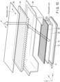
- FIG. 1 is an exploded view of an aerial display apparatus 1 according to the embodiment of the present invention.
- the X direction represents a direction along one side of the aerial display apparatus 1
- the Y direction represents a direction orthogonal to the X direction on a horizontal plane
- the Z direction represents a direction orthogonal to the XY plane (also referred to as a normal direction).
- FIG. 2 is a plan view of the aerial display apparatus 1 shown in FIG. 1 .
- FIG. 3 is a cross-sectional view of the aerial display apparatus 1 taken along line A-A' of FIG. 2 .
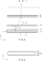
- FIG. 4 is a side view of a main part of the aerial display apparatus 1.
- the aerial display apparatus 1 denotes an apparatus that displays images (including moving images).
- the aerial display apparatus 1 displays an aerial image in an aerial space above the light emitting surface of the apparatus itself.
- the light emitting surface of the aerial display apparatus 1 denotes a surface of a component disposed in the uppermost layer of multiple components that constitute the aerial display apparatus 1.
- An aerial image denotes a real image formed in the aerial space.
- the aerial display apparatus 1 includes a lighting device (also referred to as a backlight) 10, a display device 20, an alignment control device 30, an optical device 40, a polarizing device 50, and a housing 60.
- the lighting device 10, the display device 20, the alignment control device 30, the optical device 40, and the polarizing device 50 are arranged in this order along the Z direction and are arranged parallel to each other.
- the lighting device 10, the display device 20, and the alignment control device 30 are fixed at desired positions by fixing members (not shown) with desired spaces therebetween.
- the lighting device 10 produces illumination light and outputs the illumination light toward the display device 20.
- the lighting device 10 includes a light source unit 11, a light guide plate 12, and a reflective sheet 13.
- the lighting device 10 may be a sidelight-type lighting device.
- the lighting device 10 forms a surface light source.
- the lighting device 10 may be configured in such a manner that the light intensity in an oblique direction at the angle ⁇ 1 described later reaches its peak.
- the light source unit 11 is disposed so as to face the side surface of the light guide plate 12.
- the light source unit 11 produces light toward the side surface of the light guide plate 12.
- the light source unit 11 includes a plurality of light emitting elements formed of, for example, a white light emitting diode (LED).
- the light guide plate 12 guides the illumination light from the light source unit 11 and outputs the illumination light from the upper surface thereof.
- the reflective sheet 13 reflects the illumination light output from the bottom surface of the light guide plate 12 toward the light guide plate 12 again.
- the lighting device 10 may include an optical device (including a prism sheet and a diffusion sheet) for improving optical characteristics on the upper surface of the light guide plate 12.
- the display device 20 is a transmissive display device.
- the display device 20 is configured by, for example, a liquid crystal display device.
- the driving mode of the display device 20 is not particularly limited, and a twisted nematic (TN) mode, a vertical alignment (VA) mode, a homogeneous mode, or the like, can be used.
- the display device 20 receives the illumination light output from the lighting device 10.
- the display device 20 transmits the illumination light from the lighting device 10 and performs optical modulation.
- the display device 20 thereby displays a desired image on its display surface.
- FIG. 5 is a side view of the display device 20 shown in FIG. 1 .
- the display device 20 includes a liquid crystal panel (also referred to as a display panel) 20A, a polarizing plate 20B, and a polarizing plate 20C.
- the liquid crystal panel 20A includes two transparent substrates, a liquid crystal layer sandwiched between the two transparent substrates, and switching elements corresponding in number to pixels.
- the polarizing plate 20B is provided on the lighting device 10 side of the liquid crystal panel 20A, and the polarizing plate 20C is provided on the alignment control device 30 side of the liquid crystal panel 20A.
- the polarizing plates 20B and 20C are each a linear polarizer and have a polarization axis.
- the polarization axis has the same meaning as a transmission axis.
- the polarizing plates 20B and 20C each transmit linearly polarized light (a linearly polarized light component) having a plane of vibration parallel to the polarization axis.
- the polarizing plates 20B and 20C are arranged, for example, such that their polarization axes are orthogonal to each other, that is, arranged in a crossed-Nicol state.
- the relationship between the polarization axes of the polarizing plates 20B and 20C is appropriately set according to the driving mode and the display mode (either normally black or normally white).
- the display device 20 outputs display light composed of linearly polarized light parallel to the polarization axis of the uppermost polarizing plate 20C.
- the polarization axis of the uppermost polarizing plate 20C is referred to as a polarization axis of the display device 20.
- the polarization axis of the display device 20 is set in the Y direction.
- the display device 20 may include an optical device for improving optical characteristics on the upper surface of the polarizing plate 20C.
- the alignment control device 30 has a function of reducing unnecessary light.
- the unnecessary light indicates light components not contributing to production of an aerial image, and includes light components transmitted through the optical device 40 in the normal direction.
- the alignment control device 30 is configured to transmit light components within a predetermined angular range defined around an oblique direction of an angle ⁇ 1 with respect to the normal direction and to shield light components other than the angular range. The detailed configuration of the alignment control device 30 will be described later.
- the optical device 40 reflects light incident from the bottom surface side to the upper surface side.
- the optical device 40 may also reflect the light obliquely incident from the bottom surface side, for example, in the front direction (normal direction).
- the detailed configuration of the optical device 40 will be described later.
- the optical device 40 forms an aerial image 2 in the aerial space.
- the aerial image 2 is a two-dimensional image parallel to the device surface of the optical device 40.
- the device surface denotes a virtual plane on which the optical device 40 extends in an in-plane direction.
- the device surface has the same meaning as an in-plane direction. The same applies to the device surfaces of other devices.
- a viewer 3 in front of the optical device 40 can visually recognize the aerial image 2.
- the polarizing device 50 is a linear polarizer and has a polarization axis. Of light having planes of vibration in random directions, the polarizing device 50 transmits linearly polarized light (a linearly polarized light component) having a plane of vibration parallel to the polarization axis.
- the polarization axis of the polarizing device 50 is set in the Y direction. That is, the polarization axis of the polarizing device 50 is set to be parallel to the polarization axis of the display device 20.
- the polarizing device 50 may be adhered to the upper surface of the optical device 40 by using a transparent adhesive, or may be arranged with a desired space from the optical device 40. In a case where the optical device 40 and the polarizing device 50 are arranged with a desired space therebetween, the polarizing device 50 is fixed by a fixing member (not shown).
- FIG. 6 is a cross-sectional view of the housing 60 extracted.
- the housing 60 has a rectangular box shape.
- the housing 60 is configured by one bottom plate and four side plates.
- the bottom plate is provided with a quadrangular opening 60A.
- the opening 60A is for allowing light emitted from the alignment control device 30 to pass through.
- a laminated structure configured by the lighting device 10, the display device 20, and the alignment control device 30 is fixed to the bottom plate of the housing 60 by using a fixing member (not shown).
- the alignment control device 30 is exposed from the opening 60A.
- the housing 60 is formed to surround the optical device 40.
- the housing 60 has, at its upper portion, a stepped portion 60B for fixing the optical device 40.
- the optical device 40 is fixed to the housing 60 so as to be placed on the stepped portion 60B of the housing 60.
- the housing 60 has a function of holding the alignment control device 30 and the optical device 40 with a desired space therebetween.
- the housing 60 is desirably made of a material capable of reducing reflection of light.
- the housing 60 is made of, for example, a black resin.
- FIG. 6 shows an enlarged view of the inner surface of the housing 60.
- the inner surface of the housing 60 is subjected to a roughening treatment.
- the roughened surface can reduce reflection of light.
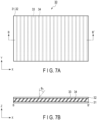
- FIG. 7A is a plan view of the alignment control device 30 shown in FIG. 1 .
- FIG. 7B is a cross-sectional view of the alignment control device 30 taken along line B-B' of FIG. 7A .
- the base member 31 is formed to be a quadrangular plane.
- the base member 31 transmits light.
- a plurality of transparent members 33 are provided on the base member 31 and aligned in the X direction, each extending in the Y direction.
- a plurality of light shielding members 34 are also provided on the base member 31 and aligned in the X direction, each extending in the Y direction.
- the transparent members 33 and the light shielding members 34 are alternately arranged in such a manner that adjacent ones are in contact with each other.
- the base member 32 is provided on the transparent members 33 and the light shielding members 34.
- the base member 32 is formed to be a quadrangular plane.
- the base member 32 transmits light.
- the transparent members 33 respectively extend on the XZ plane in an oblique direction at an angle ⁇ 1 with respect to the normal direction of the base member 31.
- Each of the transparent members 33 has a parallelogram shape with its side surface inclined at the angle ⁇ 1 on the XZ plane.
- the transparent member 33 transmits light.
- the light shielding members 34 respectively extend on the XZ plane in an oblique direction at an angle ⁇ 1 with respect to the normal direction of the base member 31.
- Each of the light shielding members 34 has a parallelogram shape with its side surface inclined at the angle ⁇ 1 on the XZ plane. The light shielding member 34 shields light.
- Any two adjacent light shielding members 34 are disposed in such a manner that the end portions thereof slightly overlap each other in the Z direction.
- the base members 31 and 32 and the transparent members 33 are formed of a transparent resin.
- the transparent resin includes an acrylic resin.
- the light shielding members 34 are formed of, for example, a resin mixed with a black colorant or pigment.
- the alignment control device 30 may be configured without one or both of the base members 31 and 32.
- the function of the alignment control device 30 can be realized at least with the transparent members 33 and the light shielding members 34 alternately arranged.
- the alignment control device 30 configured as described above transmits the display light in such a manner that the light intensity in an oblique direction at the angle ⁇ 1 with respect to the normal direction reaches its peak.
- the angle ⁇ 1 is set to be, for example, 10 degrees or more and 60 degrees or less.
- the alignment control device 30 is configured, for example, to shield light components other than the range of 30° ⁇ 30° with respect to the normal direction. It is more preferable that the alignment control device 30 be configured to shield light components other than the range of 30° ⁇ 20° with respect to the normal direction.
- the alignment control device 30 may be disposed between the lighting device 10 and the display device 20.
- the aerial display apparatus 1 may be configured without an alignment control device 30.
- FIG. 8 is a perspective view of the optical device 40 shown in FIG. 1 .
- FIG. 8 also shows a side view of a part of the optical device 40 in an enlarged manner.
- the optical device 40 includes a base member 41 and a plurality of optical elements 42.
- the base member 41 is formed to be planar on the XY plane and has a rectangular parallelepiped shape.
- a plurality of optical elements 42 are provided on the bottom surface of the base member 41.
- Each of the optical elements 42 is formed to be a triangular prism.
- the optical elements 42 are disposed such that the three side surfaces of each triangular prism extend parallel to the XY plane with one of the side surfaces being in contact with the base member 41.
- the optical elements 42 each extend in the Y direction and are aligned in the X direction. In other words, the optical elements 42 form a sawtooth shape.
- Each of the optical elements 42 has an incident surface 43 and a reflection surface 44.
- the left side surface is the incident surface 43 and the right side surface is the reflection surface 44.
- the incident surface 43 light from the display device 20 is incident.
- the reflection surface 44 the light externally incident on the incident surface 43 is reflected in the interior of the optical element 42.
- the incident surface 43 and the reflection surface 44 have an angle ⁇ p .
- the optical elements 42 may be formed integrally with the base member 41, using the same transparent material as the base member 41.
- the base member 41 and the optical elements 42 may be formed separately, and the optical elements 42 may be adhered to the base member 41, using a transparent adhesive.
- Examples of the transparent material for the base member 41 and the optical elements 42 include an acrylic resin or glass.
- the optical device 40 internally reflects incident light and thereby forms a real image in the aerial space.
- the optical device 40 forms a real image at a position in front of its device surface.
- FIG. 9 is a block diagram of the aerial display apparatus 1.
- the aerial display apparatus 1 includes a control unit 70, a storage unit 71, an input/output interface (input/output IF) 72, a display unit 73, and an input unit 74.
- the control unit 70, the storage unit 71, and the input/output interface 72 are connected to each other via a bus 75.
- the input/output interface 72 is connected to the display unit 73 and the input unit 74.
- the input/output interface 72 performs interface processing corresponding to a predetermined standard respectively on the display unit 73 and the input unit 74.
- the display unit 73 includes the lighting device 10 and the display device 20.
- the display unit 73 displays an image.
- the control unit 70 is configured by one or more processors such as a central processing unit (CPU) or a micro processing unit (MPU).
- the control unit 70 realizes various functions by executing programs stored in the storage unit 71.
- the control unit 70 includes a display processing unit 70A and an information processing unit 70B.
- the display processing unit 70A controls the operation of the display unit 73 (in particular, the lighting device 10 and the display device 20).
- the display processing unit 70A controls ON and OFF of the lighting device 10.
- the display processing unit 70A transmits an image signal to the display device 20 to cause the display device 20 to display an image.
- the information processing unit 70B produces an image to be displayed by the aerial display apparatus 1.
- the information processing unit 70B can use image data stored in the storage unit 71.
- the information processing unit 70B may acquire image data from the outside by using a communication function (not shown).
- the storage unit 71 includes a nonvolatile storage device such as a read only memory (ROM), a hard disk drive (HDD), and a solid state drive (SSD), and a volatile storage device such as a random access memory (RAM) and a register.
- the storage unit 71 stores programs executed by the control unit 70.
- the storage unit 71 stores various data necessary for control of the control unit 70.
- the storage unit 71 stores data of an image to be displayed by the aerial display apparatus 1.
- the input unit 74 receives information input by the user.
- the information processing unit 70B can select an image to be displayed on the display unit 73 based on information received by the input unit 74.
- the arrows in FIG. 4 represent optical paths.
- the light emitted from the display device 20 is incident on the alignment control device 30.
- a light component at the angle ⁇ 1 (including light components in a predetermined angular range defined around the angle ⁇ 1 ) is transmitted through the alignment control device 30.
- the light that has been transmitted through the alignment control device 30 enters the optical device 40.
- the optical device 40 forms an image of the incident light in the aerial space on the side opposite to the alignment control device 30 and displays an aerial image 2 in the aerial space.
- FIG. 10 is a perspective view illustrating the state of light reflection on the optical device 40.
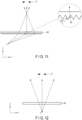
- FIG. 11 is an XZ-plane side view illustrating the state of light reflection on the optical device 40. In FIG. 11 , the optical device 40 is viewed with both eyes (i.e., a line connecting both eyes) of the viewer 3 being parallel to the X direction.
- FIG. 12 is a YZ-plane side view illustrating the state of light reflection on the optical device 40. In FIG. 12 , the optical device 40 is viewed with both eyes of the viewer 3 being parallel to the Y direction.
- the light emitted from an arbitrary point "o" on the device surface of the alignment control device 30 enters the incident surfaces 43 of the optical device 40 and reaches the reflection surfaces 44.
- the light that has reached the reflection surfaces 44 to have an angle larger than the critical angle with respect to the normal direction of the reflection surfaces 44 is totally reflected on the reflection surfaces 44 and is output from the side of the plane of the optical device 40 opposite to the side of the optical elements 42.
- the critical angle denotes the smallest angle of incidence beyond which total reflection occurs.
- the critical angle is the angle relative to the normal of the incident surface.
- the light emitted from the point "o" is totally reflected on the reflection surfaces 44 of the optical elements 42.
- the light produces an aerial image in the aerial space.
- the light emitted from the point "o" is not reflected on the reflection surfaces 44 of the optical elements 42, performing no image formation in the aerial space. The light therefore does not contribute to the formation of an aerial image.
- the condition under which the viewer 3 can recognize an aerial image is when both eyes of the viewer 3 are parallel to the X direction or approximately parallel (e.g., ⁇ 10 degrees with respect to the X direction). Furthermore, in the state of both eyes of the viewer 3 being parallel to or approximately parallel to the X direction, if the viewpoint is shifted along the Y direction, an aerial image can always be recognized.
- FIG. 13 is a diagram illustrating angular conditions of the incident surface 43 and the reflection surface 44 of the optical device 40.
- the angle of the incident surface 43 with respect to the Z direction (the direction perpendicular to the device surface) is ⁇ 2
- the angle of the reflection surface 44 with respect to the Z direction is ⁇ 3
- the angle between the incident surface 43 and the reflection surface 44 is ⁇ p .
- the light emitted from the display device 20 at the angle ⁇ 1 is incident on the incident surfaces 43.
- the refractive index of the material of the optical device 40 is n p
- the refractive index of air is 1.
- the incident angle is ⁇ 4
- the refraction angle is ⁇ 5
- the reflection surface 44 the incident angle is ⁇ 6
- the incident angle is ⁇ 8
- the refraction angle is ⁇ 9 .
- the refraction angle ⁇ 9 is the output angle.
- the incident angle ⁇ 6 on the reflection surface 44 is set to be larger than the critical angle on the reflection surface 44.
- the angle ⁇ 3 of the reflection surface 44 is determined such that the incident angle of the light incident on the reflection surface 44 is larger than the critical angle.
- the light incident on the incident surface 43 is set so as to cause no total reflection on the incident surface 43.
- the angle ⁇ 2 of the incident surface 43 is determined such that the incident angle of the light incident on the incident surface 43 is smaller than the critical angle.
- the angle between the device surface of the optical device 40 and the plane of the aerial image 2 and the distance between the device surface of the optical device 40 and the plane of the aerial image 2 can be adjusted by optimally setting the angle ⁇ 1 of the light incident on the optical device 40, the refractive index of the optical device 40, the angle ⁇ 2 of the incident surface 43 of the optical device 40, and the angle ⁇ 3 of the reflection surface 44 of the optical device 40.
- the external light is light that enters the aerial display apparatus 1 from the outside of the aerial display apparatus 1.
- the external light includes sunlight and light from indoor lighting fixtures.
- the external light has a complicated distribution of the plane of vibration of light and the amplitude, phase, and frequency in the plane in all directions.
- the external light is unpolarized natural light.
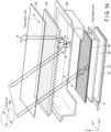
- FIG. 14 is a schematic view illustrating the behavior of external light.
- FIG. 14 is an exploded view of the aerial display apparatus 1. In FIG. 14 , one side portion of the aerial display apparatus 1 is omitted for easy understanding of the schematic view.
- the thick arrows in FIG. 14 represent the states of light.
- the double-headed arrows in FIG. 14 represent the polarization direction.
- the light component that has reached the alignment control device 30 (point "A") is irradiated onto the light shielding members 34 of the alignment control device 30 and absorbed by the light shielding members 34. Therefore, the linearly polarized light that has been transmitted through the polarizing device 50 is not reflected on the alignment control device 30.
- the light component that has been transmitted through the polarizing device 50 also reaches the bottom plate of the housing 60.
- the light component that has reached the bottom plate of the housing 60 (point "B") is diffused and reflected because of the rough surface of the housing 60. Being diffused and reflected means that light is reflected in various directions on a reflection surface.
- the light component diffused and reflected on the bottom plate of the housing 60 is in a non-polarized state.
- the light component diffused and reflected on the bottom plate of the housing 60 is transmitted through the optical device 40, reflected in the Z direction, and incident on the polarizing device 50.
- a light component (linearly polarized light) parallel to the polarization axis of the polarizing device 50 is transmitted through the polarizing device 50, and the other light components are absorbed by the polarizing device 50.
- the light component that has been transmitted through the polarizing device 50 is output from the aerial display apparatus 1 toward the viewer.
- FIG. 15 is a schematic view illustrating the behavior of display light.
- the thick arrows in FIG. 15 represent the states of light.
- the double-headed arrows in FIG. 15 represent the polarization direction.
- the display light emitted from the display device 20 is composed of linearly polarized light parallel to the polarization axis of the display device 20.
- the display light emitted from the display device 20 transmits through the alignment control device 30.
- the light component transmitted through the alignment control device 30 is transmitted through the optical device 40, reflected in the Z direction, and incident on the polarizing device 50.
- the polarization axis of the display device 20 and the polarization axis of the polarizing device 50 are set to be parallel to each other.
- the light component entering the polarizing device 50 is transmitted through the polarizing device 50 with substantially no decrease in light intensity.
- the light component transmitted through the polarizing device 50 is output from the aerial display apparatus 1 toward the viewer.
- the transmittance of the polarizing device 50 for linearly polarized light parallel to the polarization axis of the polarizing device 50 is 100%.
- the transmittance of the display light emitted from the display device 20 is 100% in principle.
- the light emitted from the display device 20 is reflected on the optical device 40, and thus an aerial image can be displayed in an aerial space. Moreover, it is possible to display an aerial image in the front direction of the aerial display apparatus 1.
- the external light incident on the aerial display apparatus 1 and reflected on the housing 60 is transmitted through the polarizing device 50 twice. This can reduce the intensity of the external light emitted from the aerial display apparatus 1. That is, it is possible to reduce an unnecessary light component not contributing to the display of the aerial image.
- the housing 60 is formed of black resin, and the inner surface of the housing 60 is roughened. Thus, the light component diffused and reflected on the housing 60 can be reduced. This can reduce the intensity of the external light emitted from the aerial display apparatus 1.
- part of the external light that has been transmitted through the polarizing device 50 is absorbed by the light shielding members 34 of the alignment control device 30. That is, it is possible to prevent part of the external light incident on the alignment control device 30 from being reflected toward the viewer. This can improve a display quality of the aerial display apparatus 1.
- the display light emitted from the display device 20 is transmitted through the polarizing device 50 substantially as it is. Therefore, it is possible to suppress a decrease in the light intensity of the display light emitted from the display device 20. This can realize an aerial display apparatus 1 capable of improving a display quality.
- the viewer 3 can visually recognize an aerial image when observing the optical device 40 in a state of both his/her eyes being parallel to or approximately parallel to the X direction (i.e., the direction of the optical elements 42 being aligned). Furthermore, an aerial image can be continuously recognized when the viewer 3 shifts the viewpoint along the Y direction in a state of both his/her eyes being parallel to or approximately parallel to the X direction. That is, it is possible to secure a viewing angle in a state of both eyes of the viewer 3 being parallel to or approximately parallel to the X direction.
- a plurality of elements constituting the aerial display apparatus 1 can be arranged in parallel. This can realize an aerial display apparatus 1 that is downsized in the Z direction.
- the display device 20 and the optical device 40 are arranged in parallel.
- the present invention is not limited to this, and the display device 20 may be arranged obliquely with respect to the optical device 40.
- the angle between the display device 20 and the optical device 40 is set to be in a range of larger than 0 degrees and smaller than 45 degrees.
- the left side surface of the optical element 42 is defined as the incident surface 43, and the right side surface is defined as the reflection surface 44.
- the invention is not limited thereto, and the incident surface 43 and the reflection surface 44 may be configured reversely. In this case, the operation of the aerial display apparatus 1 described in the embodiment is also reversed in the horizontal direction.
- the liquid crystal display device is described as an example of the display device 20, but the display device 20 is not limited to this.
- the display device 20 a self-luminous organic electroluminescence (EL) display device, a micro-light-emitting diode (microLED) display device, or the like can be used.
- EL organic electroluminescence
- microLED micro-light-emitting diode
- the microLED display device light in red (R), green (G), and blue (B) that constitutes a pixel is respectively emitted by an LED.
- the lighting device 10 is not necessary.
- the present invention is not limited to the above embodiments, and various modifications can be made without departing from the gist of the present invention at an implementation stage.
- the embodiments may be appropriately combined with each other, and in such a case, combined effects can be attained.
- various inventions are included in the above-described embodiments, and various inventions can be extracted by combining selected ones of the disclosed structural components. Even if some structural components are omitted from the structural components shown in the embodiment, the configuration without these structural components can be extracted as an invention if the problem can be solved and the effects can be attained.
Landscapes
- Physics & Mathematics (AREA)
- Nonlinear Science (AREA)
- General Physics & Mathematics (AREA)
- Optics & Photonics (AREA)
- Mathematical Physics (AREA)
- Chemical & Material Sciences (AREA)
- Crystallography & Structural Chemistry (AREA)
- Engineering & Computer Science (AREA)
- Multimedia (AREA)
- Signal Processing (AREA)
- Testing, Inspecting, Measuring Of Stereoscopic Televisions And Televisions (AREA)
- Optical Elements Other Than Lenses (AREA)
Abstract
Description
- The present invention relates to an aerial display apparatus.
- Aerial display apparatuses capable of displaying still images, moving images, and the like as aerial images have been developed, and are expected to serve as new human-machine interfaces. For instance, an aerial display apparatus includes a dihedral corner reflector array, in which dihedral corner reflectors are arranged into an array, and reflects light emitted from the display surface of a display device to thereby form a real image in the air. With the display method adopting a dihedral corner reflector array, a real image (aerial image) can be displayed at a plane-symmetric position without an aberration.
-
Patent Document 1 discloses an optical device using transparent quadrangular prisms that protrude from the surface of a flat transparent plate as dihedral corner reflectors, in which the quadrangular prisms are arranged into an array on a plane.Patent Document 2 discloses an optical device in which first and second light control panels, each of which is formed by vertically aligning a plurality of planar light reflecting portions inside a flat transparent plate, are arranged in such a manner that the planar light reflecting portions of the two panels are orthogonal to each other. In the optical devices disclosed inPatent Documents - On display apparatuses adopting the optical device of
Patent Document -
- Patent Document 1:
Jpn. Pat. Appln. KOKAI Publication No. 2011-191404 - Patent Document 2:
Jpn. Pat. Appln. KOKAI Publication No. 2011-175297 - The present invention is to provide an aerial display apparatus capable of improving a display quality.
- A first aspect of the present invention provides an aerial display apparatus comprising:
- a display device configured to display an image;
- an optical device arranged to receive light from the display device and configured to reflect light from the display device to a side opposite to the display device to form an aerial image in an aerial space;
- a polarizing device arranged to receive light from the optical device and configured to transmit linearly polarized light; and
- a housing formed to surround the optical device and configured to fix the display device and the optical device with a space therebetween,
- a polarization axis of the polarizing device being parallel to a polarization axis of the display device.
- A second aspect of the present invention provides the aerial display apparatus according to the first aspect, wherein
- the housing includes a bottom plate having an opening, and
- the display device is arranged such that the light from the display device passes through the opening.
- A third aspect of the present invention provides the aerial display apparatus according to the first aspect, wherein
- the optical device includes a planar base member, and a plurality of optical elements provided below the base member, each extending in a first direction and aligned in a second direction orthogonal to the first direction, and
- each of the optical elements has an incident surface and a reflection surface which are inclined with respect to a normal direction of the base member and are in contact with each other.
- A fourth aspect of the present invention provides the aerial display apparatus according to the first aspect, wherein
the display device, the optical device and the polarizing device are arranged in parallel to each other. - A fifth aspect of the present invention provides the aerial display apparatus according to the first aspect, further comprising:
an alignment control device arranged between the display device and the optical device and transmitting part of the light from the display device. - A sixth aspect of the present invention provides the aerial display apparatus according to the fifth aspect, wherein
- the alignment control device includes a plurality of transparent members and a plurality of light shielding members alternately arranged, and
- the light shielding members are inclined with respect to a normal direction of the alignment control device.
- A seventh aspect of the present invention provides the aerial display apparatus according to the fifth, wherein
the display device and the alignment control device are arranged in parallel to each other. - An eighth aspect of the present invention provides the aerial display apparatus according to the first aspect, further comprising:
- a lighting device configured to produce light,
- wherein the display device is arranged to receive light from the lighting device and is configured by a liquid crystal display device.
- According to the present invention, an aerial display apparatus capable of improving a display quality can be provided.
-
-
FIG. 1 is an exploded view of an aerial display apparatus according to the embodiment of the present invention. -
FIG. 2 is a plan view of the aerial display apparatus shown inFIG. 1 . -
FIG. 3 is a cross-sectional view of the aerial display apparatus taken along line A-A' ofFIG. 2 . -
FIG. 4 is a side view of a main part of the aerial display apparatus. -
FIG. 5 is a side view of a display device shown inFIG. 1 . -
FIG. 6 is a cross-sectional view of a housing extracted. -
FIG. 7A is a plan view of an alignment control device shown inFIG. 1 . -
FIG. 7B is a cross-sectional view of the alignment control device taken along line B-B' ofFIG. 7A . -
FIG. 8 is a perspective view of an optical device shown inFIG. 1 . -
FIG. 9 is a block diagram of the aerial display apparatus. -
FIG. 10 is a perspective view illustrating the state of light reflection on the optical device. -
FIG. 11 is an XZ-plane side view illustrating the state of light reflection on the optical device. -
FIG. 12 is a YZ-plane side view illustrating the state of light reflection on the optical device. -
FIG. 13 is a diagram illustrating angular conditions of an incident surface and a reflection surface of the optical device. -
FIG. 14 is a schematic view illustrating behavior of external light. -
FIG. 15 is a schematic view illustrating behavior of display light. - Embodiments will be described below with reference to the drawings. These drawings are schematically or conceptually illustrated, and the dimensions, ratios, and the like in each drawing may not always be the same as actual dimensions and ratios. Further, among the drawings illustrating the same portion, the dimensional relationships or ratios may differ from each other. In particular, the embodiments described below exemplify a device and a method that embody the technical idea of the present invention, and therefore the technical idea of the present invention should not be identified by the shape, configuration, arrangement, etc. of the structural components. In the description below, the same reference numerals are given to elements having the same functions and configurations, and redundant explanations may be omitted.
-
FIG. 1 is an exploded view of anaerial display apparatus 1 according to the embodiment of the present invention. InFIG. 1 , the X direction represents a direction along one side of theaerial display apparatus 1, the Y direction represents a direction orthogonal to the X direction on a horizontal plane, and the Z direction represents a direction orthogonal to the XY plane (also referred to as a normal direction).FIG. 2 is a plan view of theaerial display apparatus 1 shown inFIG. 1 .FIG. 3 is a cross-sectional view of theaerial display apparatus 1 taken along line A-A' ofFIG. 2 .FIG. 4 is a side view of a main part of theaerial display apparatus 1. - The
aerial display apparatus 1 denotes an apparatus that displays images (including moving images). Theaerial display apparatus 1 displays an aerial image in an aerial space above the light emitting surface of the apparatus itself. The light emitting surface of theaerial display apparatus 1 denotes a surface of a component disposed in the uppermost layer of multiple components that constitute theaerial display apparatus 1. An aerial image denotes a real image formed in the aerial space. - The
aerial display apparatus 1 includes a lighting device (also referred to as a backlight) 10, adisplay device 20, analignment control device 30, anoptical device 40, apolarizing device 50, and ahousing 60. Thelighting device 10, thedisplay device 20, thealignment control device 30, theoptical device 40, and thepolarizing device 50 are arranged in this order along the Z direction and are arranged parallel to each other. Thelighting device 10, thedisplay device 20, and thealignment control device 30 are fixed at desired positions by fixing members (not shown) with desired spaces therebetween. - The
lighting device 10 produces illumination light and outputs the illumination light toward thedisplay device 20. Thelighting device 10 includes alight source unit 11, alight guide plate 12, and areflective sheet 13. Thelighting device 10 may be a sidelight-type lighting device. Thelighting device 10 forms a surface light source. Thelighting device 10 may be configured in such a manner that the light intensity in an oblique direction at the angle θ1 described later reaches its peak. - The
light source unit 11 is disposed so as to face the side surface of thelight guide plate 12. Thelight source unit 11 produces light toward the side surface of thelight guide plate 12. Thelight source unit 11 includes a plurality of light emitting elements formed of, for example, a white light emitting diode (LED). Thelight guide plate 12 guides the illumination light from thelight source unit 11 and outputs the illumination light from the upper surface thereof. Thereflective sheet 13 reflects the illumination light output from the bottom surface of thelight guide plate 12 toward thelight guide plate 12 again. Thelighting device 10 may include an optical device (including a prism sheet and a diffusion sheet) for improving optical characteristics on the upper surface of thelight guide plate 12. - The
display device 20 is a transmissive display device. Thedisplay device 20 is configured by, for example, a liquid crystal display device. The driving mode of thedisplay device 20 is not particularly limited, and a twisted nematic (TN) mode, a vertical alignment (VA) mode, a homogeneous mode, or the like, can be used. Thedisplay device 20 receives the illumination light output from thelighting device 10. Thedisplay device 20 transmits the illumination light from thelighting device 10 and performs optical modulation. Thedisplay device 20 thereby displays a desired image on its display surface. -
FIG. 5 is a side view of thedisplay device 20 shown inFIG. 1 . Thedisplay device 20 includes a liquid crystal panel (also referred to as a display panel) 20A, apolarizing plate 20B, and apolarizing plate 20C. Theliquid crystal panel 20A includes two transparent substrates, a liquid crystal layer sandwiched between the two transparent substrates, and switching elements corresponding in number to pixels. Thepolarizing plate 20B is provided on thelighting device 10 side of theliquid crystal panel 20A, and thepolarizing plate 20C is provided on thealignment control device 30 side of theliquid crystal panel 20A. - The
polarizing plates polarizing plates polarizing plates polarizing plates - The
display device 20 outputs display light composed of linearly polarized light parallel to the polarization axis of the uppermostpolarizing plate 20C. In the present embodiment, the polarization axis of the uppermostpolarizing plate 20C is referred to as a polarization axis of thedisplay device 20. As shown inFIG. 1 , the polarization axis of thedisplay device 20 is set in the Y direction. Thedisplay device 20 may include an optical device for improving optical characteristics on the upper surface of thepolarizing plate 20C. - The
alignment control device 30 has a function of reducing unnecessary light. The unnecessary light indicates light components not contributing to production of an aerial image, and includes light components transmitted through theoptical device 40 in the normal direction. Thealignment control device 30 is configured to transmit light components within a predetermined angular range defined around an oblique direction of an angle θ1 with respect to the normal direction and to shield light components other than the angular range. The detailed configuration of thealignment control device 30 will be described later. - The
optical device 40 reflects light incident from the bottom surface side to the upper surface side. Theoptical device 40 may also reflect the light obliquely incident from the bottom surface side, for example, in the front direction (normal direction). The detailed configuration of theoptical device 40 will be described later. Theoptical device 40 forms anaerial image 2 in the aerial space. Theaerial image 2 is a two-dimensional image parallel to the device surface of theoptical device 40. The device surface denotes a virtual plane on which theoptical device 40 extends in an in-plane direction. The device surface has the same meaning as an in-plane direction. The same applies to the device surfaces of other devices. Aviewer 3 in front of theoptical device 40 can visually recognize theaerial image 2. - The
polarizing device 50 is a linear polarizer and has a polarization axis. Of light having planes of vibration in random directions, thepolarizing device 50 transmits linearly polarized light (a linearly polarized light component) having a plane of vibration parallel to the polarization axis. The polarization axis of thepolarizing device 50 is set in the Y direction. That is, the polarization axis of thepolarizing device 50 is set to be parallel to the polarization axis of thedisplay device 20. Thepolarizing device 50 may be adhered to the upper surface of theoptical device 40 by using a transparent adhesive, or may be arranged with a desired space from theoptical device 40. In a case where theoptical device 40 and thepolarizing device 50 are arranged with a desired space therebetween, thepolarizing device 50 is fixed by a fixing member (not shown). -
FIG. 6 is a cross-sectional view of thehousing 60 extracted. Thehousing 60 has a rectangular box shape. Thehousing 60 is configured by one bottom plate and four side plates. In thehousing 60, the bottom plate is provided with aquadrangular opening 60A. Theopening 60A is for allowing light emitted from thealignment control device 30 to pass through. A laminated structure configured by thelighting device 10, thedisplay device 20, and thealignment control device 30 is fixed to the bottom plate of thehousing 60 by using a fixing member (not shown). Thealignment control device 30 is exposed from theopening 60A. - The
housing 60 is formed to surround theoptical device 40. Thehousing 60 has, at its upper portion, a steppedportion 60B for fixing theoptical device 40. Theoptical device 40 is fixed to thehousing 60 so as to be placed on the steppedportion 60B of thehousing 60. Thehousing 60 has a function of holding thealignment control device 30 and theoptical device 40 with a desired space therebetween. - The
housing 60 is desirably made of a material capable of reducing reflection of light. Thehousing 60 is made of, for example, a black resin.FIG. 6 shows an enlarged view of the inner surface of thehousing 60. For example, the inner surface of thehousing 60 is subjected to a roughening treatment. The roughened surface can reduce reflection of light. -
FIG. 7A is a plan view of thealignment control device 30 shown inFIG. 1 .FIG. 7B is a cross-sectional view of thealignment control device 30 taken along line B-B' ofFIG. 7A . - The
base member 31 is formed to be a quadrangular plane. Thebase member 31 transmits light. - A plurality of
transparent members 33 are provided on thebase member 31 and aligned in the X direction, each extending in the Y direction. A plurality oflight shielding members 34 are also provided on thebase member 31 and aligned in the X direction, each extending in the Y direction. Thetransparent members 33 and thelight shielding members 34 are alternately arranged in such a manner that adjacent ones are in contact with each other. - The
base member 32 is provided on thetransparent members 33 and thelight shielding members 34. Thebase member 32 is formed to be a quadrangular plane. Thebase member 32 transmits light. - The
transparent members 33 respectively extend on the XZ plane in an oblique direction at an angle θ1 with respect to the normal direction of thebase member 31. Each of thetransparent members 33 has a parallelogram shape with its side surface inclined at the angle θ1 on the XZ plane. Thetransparent member 33 transmits light. - The
light shielding members 34 respectively extend on the XZ plane in an oblique direction at an angle θ1 with respect to the normal direction of thebase member 31. Each of thelight shielding members 34 has a parallelogram shape with its side surface inclined at the angle θ1 on the XZ plane. Thelight shielding member 34 shields light. - Any two adjacent
light shielding members 34 are disposed in such a manner that the end portions thereof slightly overlap each other in the Z direction. - The
base members transparent members 33 are formed of a transparent resin. The transparent resin includes an acrylic resin. Thelight shielding members 34 are formed of, for example, a resin mixed with a black colorant or pigment. - The
alignment control device 30 may be configured without one or both of thebase members alignment control device 30 can be realized at least with thetransparent members 33 and thelight shielding members 34 alternately arranged. - The
alignment control device 30 configured as described above transmits the display light in such a manner that the light intensity in an oblique direction at the angle θ1 with respect to the normal direction reaches its peak. The angle θ1 is set to be, for example, 10 degrees or more and 60 degrees or less. Thealignment control device 30 is configured, for example, to shield light components other than the range of 30°±30° with respect to the normal direction. It is more preferable that thealignment control device 30 be configured to shield light components other than the range of 30° ± 20° with respect to the normal direction. - As a modification, the
alignment control device 30 may be disposed between thelighting device 10 and thedisplay device 20. Alternatively, theaerial display apparatus 1 may be configured without analignment control device 30. -
FIG. 8 is a perspective view of theoptical device 40 shown inFIG. 1 .FIG. 8 also shows a side view of a part of theoptical device 40 in an enlarged manner. - The
optical device 40 includes abase member 41 and a plurality ofoptical elements 42. Thebase member 41 is formed to be planar on the XY plane and has a rectangular parallelepiped shape. - A plurality of
optical elements 42 are provided on the bottom surface of thebase member 41. Each of theoptical elements 42 is formed to be a triangular prism. Theoptical elements 42 are disposed such that the three side surfaces of each triangular prism extend parallel to the XY plane with one of the side surfaces being in contact with thebase member 41. Theoptical elements 42 each extend in the Y direction and are aligned in the X direction. In other words, theoptical elements 42 form a sawtooth shape. - Each of the
optical elements 42 has anincident surface 43 and areflection surface 44. When viewed from the Y direction, the left side surface is theincident surface 43 and the right side surface is thereflection surface 44. Upon theincident surface 43, light from thedisplay device 20 is incident. Upon thereflection surface 44, the light externally incident on theincident surface 43 is reflected in the interior of theoptical element 42. Theincident surface 43 and thereflection surface 44 have an angle θp. - The
optical elements 42 may be formed integrally with thebase member 41, using the same transparent material as thebase member 41. Thebase member 41 and theoptical elements 42 may be formed separately, and theoptical elements 42 may be adhered to thebase member 41, using a transparent adhesive. Examples of the transparent material for thebase member 41 and theoptical elements 42 include an acrylic resin or glass. - The
optical device 40 internally reflects incident light and thereby forms a real image in the aerial space. Theoptical device 40 forms a real image at a position in front of its device surface. -
FIG. 9 is a block diagram of theaerial display apparatus 1. Theaerial display apparatus 1 includes acontrol unit 70, astorage unit 71, an input/output interface (input/output IF) 72, adisplay unit 73, and aninput unit 74. Thecontrol unit 70, thestorage unit 71, and the input/output interface 72 are connected to each other via abus 75. - The input/
output interface 72 is connected to thedisplay unit 73 and theinput unit 74. The input/output interface 72 performs interface processing corresponding to a predetermined standard respectively on thedisplay unit 73 and theinput unit 74. - The
display unit 73 includes thelighting device 10 and thedisplay device 20. Thedisplay unit 73 displays an image. - The
control unit 70 is configured by one or more processors such as a central processing unit (CPU) or a micro processing unit (MPU). Thecontrol unit 70 realizes various functions by executing programs stored in thestorage unit 71. Thecontrol unit 70 includes adisplay processing unit 70A and aninformation processing unit 70B. - The
display processing unit 70A controls the operation of the display unit 73 (in particular, thelighting device 10 and the display device 20). Thedisplay processing unit 70A controls ON and OFF of thelighting device 10. Thedisplay processing unit 70A transmits an image signal to thedisplay device 20 to cause thedisplay device 20 to display an image. - The
information processing unit 70B produces an image to be displayed by theaerial display apparatus 1. Theinformation processing unit 70B can use image data stored in thestorage unit 71. Theinformation processing unit 70B may acquire image data from the outside by using a communication function (not shown). - The
storage unit 71 includes a nonvolatile storage device such as a read only memory (ROM), a hard disk drive (HDD), and a solid state drive (SSD), and a volatile storage device such as a random access memory (RAM) and a register. Thestorage unit 71 stores programs executed by thecontrol unit 70. Thestorage unit 71 stores various data necessary for control of thecontrol unit 70. Thestorage unit 71 stores data of an image to be displayed by theaerial display apparatus 1. - The
input unit 74 receives information input by the user. Theinformation processing unit 70B can select an image to be displayed on thedisplay unit 73 based on information received by theinput unit 74. - Next, the operation of the
aerial display apparatus 1 configured as above will be described. - The arrows in
FIG. 4 represent optical paths. As shown inFIG. 4 , the light emitted from thedisplay device 20 is incident on thealignment control device 30. In the light emitted from thedisplay device 20, a light component at the angle θ1 (including light components in a predetermined angular range defined around the angle θ1) is transmitted through thealignment control device 30. The light that has been transmitted through thealignment control device 30 enters theoptical device 40. Theoptical device 40 forms an image of the incident light in the aerial space on the side opposite to thealignment control device 30 and displays anaerial image 2 in the aerial space. -
FIG. 10 is a perspective view illustrating the state of light reflection on theoptical device 40.FIG. 11 is an XZ-plane side view illustrating the state of light reflection on theoptical device 40. InFIG. 11 , theoptical device 40 is viewed with both eyes (i.e., a line connecting both eyes) of theviewer 3 being parallel to the X direction.FIG. 12 is a YZ-plane side view illustrating the state of light reflection on theoptical device 40. InFIG. 12 , theoptical device 40 is viewed with both eyes of theviewer 3 being parallel to the Y direction. - The light emitted from an arbitrary point "o" on the device surface of the
alignment control device 30 enters the incident surfaces 43 of theoptical device 40 and reaches the reflection surfaces 44. The light that has reached the reflection surfaces 44 to have an angle larger than the critical angle with respect to the normal direction of the reflection surfaces 44 is totally reflected on the reflection surfaces 44 and is output from the side of the plane of theoptical device 40 opposite to the side of theoptical elements 42. The critical angle denotes the smallest angle of incidence beyond which total reflection occurs. The critical angle is the angle relative to the normal of the incident surface. - In the XZ plane of
FIG. 11 , the light emitted from the point "o" is totally reflected on the reflection surfaces 44 of theoptical elements 42. The light produces an aerial image in the aerial space. - In the YZ plane of
FIG. 12 , the light emitted from the point "o" is not reflected on the reflection surfaces 44 of theoptical elements 42, performing no image formation in the aerial space. The light therefore does not contribute to the formation of an aerial image. - That is, the condition under which the
viewer 3 can recognize an aerial image is when both eyes of theviewer 3 are parallel to the X direction or approximately parallel (e.g., ±10 degrees with respect to the X direction). Furthermore, in the state of both eyes of theviewer 3 being parallel to or approximately parallel to the X direction, if the viewpoint is shifted along the Y direction, an aerial image can always be recognized. -
FIG. 13 is a diagram illustrating angular conditions of theincident surface 43 and thereflection surface 44 of theoptical device 40. - It is assumed that the angle of the
incident surface 43 with respect to the Z direction (the direction perpendicular to the device surface) is θ2, the angle of thereflection surface 44 with respect to the Z direction is θ3, and the angle between theincident surface 43 and thereflection surface 44 is θp. The angle θp can be expressed by the following equation (1):
- The light emitted from the
display device 20 at the angle θ1 is incident on the incident surfaces 43. It is assumed that the refractive index of the material of theoptical device 40 is np, and the refractive index of air is 1. On theincident surface 43, the incident angle is θ4, and the refraction angle is θ5. On thereflection surface 44, the incident angle is θ6, and the refraction angle is θ7 (=θ6). On the upper surface of theoptical device 40, the incident angle is θ8, and the refraction angle is θ9. The refraction angle θ9 is the output angle. The output angle θ9 can be expressed by the following equation (2):θ9 = sin-1 (np*sin(sin-1((1/np)*sin(90°-(θ1+θ2)))+θ2+2θ3- 90°)) - The critical angle of the
reflection surface 44 can be expressed by the following equation (3):

- That is, the incident angle θ6 on the
reflection surface 44 is set to be larger than the critical angle on thereflection surface 44. In other words, the angle θ3 of thereflection surface 44 is determined such that the incident angle of the light incident on thereflection surface 44 is larger than the critical angle. - The light incident on the
incident surface 43 is set so as to cause no total reflection on theincident surface 43. In other words, the angle θ2 of theincident surface 43 is determined such that the incident angle of the light incident on theincident surface 43 is smaller than the critical angle. - The angle between the device surface of the
optical device 40 and the plane of theaerial image 2 and the distance between the device surface of theoptical device 40 and the plane of theaerial image 2 can be adjusted by optimally setting the angle θ1 of the light incident on theoptical device 40, the refractive index of theoptical device 40, the angle θ2 of theincident surface 43 of theoptical device 40, and the angle θ3 of thereflection surface 44 of theoptical device 40. - Next, a detailed operation of the
aerial display apparatus 1 regarding polarization will be described. - External light is incident on the
aerial display apparatus 1. The external light is light that enters theaerial display apparatus 1 from the outside of theaerial display apparatus 1. The external light includes sunlight and light from indoor lighting fixtures. The external light has a complicated distribution of the plane of vibration of light and the amplitude, phase, and frequency in the plane in all directions. The external light is unpolarized natural light. -
FIG. 14 is a schematic view illustrating the behavior of external light.FIG. 14 is an exploded view of theaerial display apparatus 1. InFIG. 14 , one side portion of theaerial display apparatus 1 is omitted for easy understanding of the schematic view. The thick arrows inFIG. 14 represent the states of light. The double-headed arrows inFIG. 14 represent the polarization direction. - Attention is paid to external light that is obliquely incident from the side opposite to the direction in which the
light shielding members 34 are inclined with respect to the normal direction of the device surface of thealignment control device 30, that is, external light that is obliquely incident from the upper left of theaerial display apparatus 1. The external light is incident on thepolarizing device 50 from above theaerial display apparatus 1. Of the external light incident on thepolarizing device 50, a light component (linearly polarized light) parallel to the polarization axis of thepolarizing device 50 is transmitted through thepolarizing device 50, and the other light components are absorbed by thepolarizing device 50. The light component that has been transmitted through thepolarizing device 50 reaches thealignment control device 30. The light component that has reached the alignment control device 30 (point "A") is irradiated onto thelight shielding members 34 of thealignment control device 30 and absorbed by thelight shielding members 34. Therefore, the linearly polarized light that has been transmitted through thepolarizing device 50 is not reflected on thealignment control device 30. - The light component that has been transmitted through the
polarizing device 50 also reaches the bottom plate of thehousing 60. The light component that has reached the bottom plate of the housing 60 (point "B") is diffused and reflected because of the rough surface of thehousing 60. Being diffused and reflected means that light is reflected in various directions on a reflection surface. The light component diffused and reflected on the bottom plate of thehousing 60 is in a non-polarized state. - The light component diffused and reflected on the bottom plate of the
housing 60 is transmitted through theoptical device 40, reflected in the Z direction, and incident on thepolarizing device 50. Of the light incident on thepolarizing device 50, a light component (linearly polarized light) parallel to the polarization axis of thepolarizing device 50 is transmitted through thepolarizing device 50, and the other light components are absorbed by thepolarizing device 50. The light component that has been transmitted through thepolarizing device 50 is output from theaerial display apparatus 1 toward the viewer. - Attention is paid to the light component reflected on the bottom plate of the
housing 60 among the external light incident on theaerial display apparatus 1. It is assumed that the transmittance of thepolarizing device 50 for unpolarized light is 50% and the reflectance of thehousing 60 is 10%. In this case, light components output from theaerial display apparatus 1 can be reduced to 2.5% of the external light incident on theaerial display apparatus 1. - Next, the behavior of the display light emitted from the
display device 20 will be described.FIG. 15 is a schematic view illustrating the behavior of display light. The thick arrows inFIG. 15 represent the states of light. The double-headed arrows inFIG. 15 represent the polarization direction. - The display light emitted from the
display device 20 is composed of linearly polarized light parallel to the polarization axis of thedisplay device 20. The display light emitted from thedisplay device 20 transmits through thealignment control device 30. The light component transmitted through thealignment control device 30 is transmitted through theoptical device 40, reflected in the Z direction, and incident on thepolarizing device 50. The polarization axis of thedisplay device 20 and the polarization axis of thepolarizing device 50 are set to be parallel to each other. The light component entering thepolarizing device 50 is transmitted through thepolarizing device 50 with substantially no decrease in light intensity. The light component transmitted through thepolarizing device 50 is output from theaerial display apparatus 1 toward the viewer. - It is assumed that the transmittance of the
polarizing device 50 for linearly polarized light parallel to the polarization axis of thepolarizing device 50 is 100%. In this case, the transmittance of the display light emitted from thedisplay device 20 is 100% in principle. - According to the embodiment of the present invention, the light emitted from the
display device 20 is reflected on theoptical device 40, and thus an aerial image can be displayed in an aerial space. Moreover, it is possible to display an aerial image in the front direction of theaerial display apparatus 1. - The external light incident on the
aerial display apparatus 1 and reflected on thehousing 60 is transmitted through thepolarizing device 50 twice. This can reduce the intensity of the external light emitted from theaerial display apparatus 1. That is, it is possible to reduce an unnecessary light component not contributing to the display of the aerial image. - The
housing 60 is formed of black resin, and the inner surface of thehousing 60 is roughened. Thus, the light component diffused and reflected on thehousing 60 can be reduced. This can reduce the intensity of the external light emitted from theaerial display apparatus 1. - Moreover, part of the external light that has been transmitted through the
polarizing device 50 is absorbed by thelight shielding members 34 of thealignment control device 30. That is, it is possible to prevent part of the external light incident on thealignment control device 30 from being reflected toward the viewer. This can improve a display quality of theaerial display apparatus 1. - The display light emitted from the
display device 20 is transmitted through thepolarizing device 50 substantially as it is. Therefore, it is possible to suppress a decrease in the light intensity of the display light emitted from thedisplay device 20. This can realize anaerial display apparatus 1 capable of improving a display quality. - In addition, the
viewer 3 can visually recognize an aerial image when observing theoptical device 40 in a state of both his/her eyes being parallel to or approximately parallel to the X direction (i.e., the direction of theoptical elements 42 being aligned). Furthermore, an aerial image can be continuously recognized when theviewer 3 shifts the viewpoint along the Y direction in a state of both his/her eyes being parallel to or approximately parallel to the X direction. That is, it is possible to secure a viewing angle in a state of both eyes of theviewer 3 being parallel to or approximately parallel to the X direction. - In addition, a plurality of elements constituting the
aerial display apparatus 1 can be arranged in parallel. This can realize anaerial display apparatus 1 that is downsized in the Z direction. - In the embodiment described above, the
display device 20 and theoptical device 40 are arranged in parallel. The present invention is not limited to this, and thedisplay device 20 may be arranged obliquely with respect to theoptical device 40. The angle between thedisplay device 20 and theoptical device 40 is set to be in a range of larger than 0 degrees and smaller than 45 degrees. - In the embodiment described above, the left side surface of the
optical element 42 is defined as theincident surface 43, and the right side surface is defined as thereflection surface 44. The invention is not limited thereto, and theincident surface 43 and thereflection surface 44 may be configured reversely. In this case, the operation of theaerial display apparatus 1 described in the embodiment is also reversed in the horizontal direction. - In the embodiment described above, the liquid crystal display device is described as an example of the
display device 20, but thedisplay device 20 is not limited to this. As thedisplay device 20, a self-luminous organic electroluminescence (EL) display device, a micro-light-emitting diode (microLED) display device, or the like can be used. In the microLED display device, light in red (R), green (G), and blue (B) that constitutes a pixel is respectively emitted by an LED. In a case where the self-luminous display device 20 is used, thelighting device 10 is not necessary. - The present invention is not limited to the above embodiments, and various modifications can be made without departing from the gist of the present invention at an implementation stage. In addition, the embodiments may be appropriately combined with each other, and in such a case, combined effects can be attained. Furthermore, various inventions are included in the above-described embodiments, and various inventions can be extracted by combining selected ones of the disclosed structural components. Even if some structural components are omitted from the structural components shown in the embodiment, the configuration without these structural components can be extracted as an invention if the problem can be solved and the effects can be attained.
-
- 1
- Aerial display apparatus
- 2
- Aerial image
- 3
- Viewer
- 10
- Lighting device
- 11
- Light source unit
- 12
- Light guide plate
- 13
- Reflective sheet
- 20
- Display device
- 20A
- Liquid crystal panel
- 20B, 20C
- Polarizing plate
- 30
- Alignment control device
- 31, 32
- Base member
- 33
- Transparent member
- 34
- Light shielding member
- 40
- Optical device
- 41
- Base member
- 42
- Optical element
- 43
- Incident surface
- 44
- Reflection surface
- 50
- Polarizing device
- 60
- Housing
- 60A
- Opening
- 60B
- Stepped portion
- 70
- Control unit
- 70A
- Display processing unit
- 70B
- Information processing unit
- 71
- Storage unit
- 72
- Input/output interface
- 73
- Display unit
- 74
- Input unit
- 75
- Bus
Claims (8)
- An aerial display apparatus comprising:a display device configured to display an image;an optical device arranged to receive light from the display device and configured to reflect light from the display device to a side opposite to the display device to form an aerial image in an aerial space;a polarizing device arranged to receive light from the optical device and configured to transmit linearly polarized light; anda housing formed to surround the optical device and configured to fix the display device and the optical device with a space therebetween,a polarization axis of the polarizing device being parallel to a polarization axis of the display device.
- The aerial display apparatus according to claim 1, whereinthe housing includes a bottom plate having an opening, andthe display device is arranged such that the light from the display device passes through the opening.
- The aerial display apparatus according to claim 1, whereinthe optical device includes a planar base member, and a plurality of optical elements provided below the base member, each extending in a first direction and aligned in a second direction orthogonal to the first direction, andeach of the optical elements has an incident surface and a reflection surface which are inclined with respect to a normal direction of the base member and are in contact with each other.
- The aerial display apparatus according to claim 1, wherein
the display device, the optical device and the polarizing device are arranged in parallel to each other. - The aerial display apparatus according to claim 1, further comprising:
an alignment control device arranged between the display device and the optical device and transmitting part of the light from the display device. - The aerial display apparatus according to claim 5, whereinthe alignment control device includes a plurality of transparent members and a plurality of light shielding members alternately arranged, andthe light shielding members are inclined with respect to a normal direction of the alignment control device.
- The aerial display apparatus according to claim 5, wherein
the display device and the alignment control device are arranged in parallel to each other. - The aerial display apparatus according to claim 1, further comprising:a lighting device configured to produce light,wherein the display device is arranged to receive light from the lighting device and is configured by a liquid crystal display device.
Applications Claiming Priority (2)
| Application Number | Priority Date | Filing Date | Title |
|---|---|---|---|
| JP2022034416A JP7859088B2 (en) | 2022-03-07 | 2022-03-07 | aerial display device |
| PCT/JP2023/005799 WO2023171327A1 (en) | 2022-03-07 | 2023-02-17 | Aerial display device |
Publications (2)
| Publication Number | Publication Date |
|---|---|
| EP4492127A1 true EP4492127A1 (en) | 2025-01-15 |
| EP4492127A4 EP4492127A4 (en) | 2025-06-11 |
Family
ID=87936895
Family Applications (1)
| Application Number | Title | Priority Date | Filing Date |
|---|---|---|---|
| EP23766506.2A Withdrawn EP4492127A4 (en) | 2022-03-07 | 2023-02-17 | OVERHEAD DISPLAY DEVICE |
Country Status (6)
| Country | Link |
|---|---|
| US (1) | US20240419014A1 (en) |
| EP (1) | EP4492127A4 (en) |
| JP (1) | JP7859088B2 (en) |
| CN (1) | CN118829934A (en) |
| TW (1) | TWI868607B (en) |
| WO (1) | WO2023171327A1 (en) |
Family Cites Families (19)
| Publication number | Priority date | Publication date | Assignee | Title |
|---|---|---|---|---|
| JP3725945B2 (en) * | 1996-08-30 | 2005-12-14 | 和泉電気株式会社 | Switching display device and virtual switch |
| JP2003156712A (en) * | 2001-11-22 | 2003-05-30 | Pioneer Electronic Corp | Image display device |
| JP2006184542A (en) * | 2004-12-27 | 2006-07-13 | Nippon Sheet Glass Co Ltd | Space image forming apparatus and display device |
| WO2009131128A1 (en) | 2008-04-22 | 2009-10-29 | Fujishima Tomohiko | Optical imaging device and optical imaging method using the same |
| JP2011191404A (en) | 2010-03-12 | 2011-09-29 | Stanley Electric Co Ltd | Two-face corner reflector array optical element and display device using the same |
| KR101265483B1 (en) * | 2010-06-08 | 2013-05-20 | 엘지디스플레이 주식회사 | Stereoscopic image display device, and manufacturing method the same |
| WO2012165217A1 (en) | 2011-05-27 | 2012-12-06 | シャープ株式会社 | Optical element and optical system |
| JP2014130309A (en) * | 2012-03-30 | 2014-07-10 | Nitto Denko Corp | Display device |
| JP2014010161A (en) | 2012-06-27 | 2014-01-20 | Nitto Denko Corp | Display input device |
| CN107111149A (en) * | 2014-12-01 | 2017-08-29 | Sn合伙合同会社 | Aerial picture display device |
| US9875726B2 (en) | 2015-05-27 | 2018-01-23 | Neil Andrew FOSTER | Hybrid-image display device |
| JP6597536B2 (en) * | 2016-09-14 | 2019-10-30 | 株式会社デンソー | Aerial display device |
| JP2019101055A (en) | 2017-11-28 | 2019-06-24 | コニカミノルタ株式会社 | Aerial video display device |
| JP6593426B2 (en) | 2017-12-12 | 2019-10-23 | コニカミノルタ株式会社 | Aerial video display |
| EP3809189B1 (en) | 2018-06-12 | 2024-08-28 | Toppan Printing Co., Ltd. | Aerial-display apparatus |
| CN108983331B (en) * | 2018-07-24 | 2020-12-01 | 京东方科技集团股份有限公司 | A kind of semi-permeable semi-reverse film and aerial display device |
| JP7173895B2 (en) * | 2019-02-22 | 2022-11-16 | 日立チャネルソリューションズ株式会社 | Aerial image display device, transaction device, and aerial image formation control method in aerial image display device |
| JP7459563B2 (en) | 2020-03-02 | 2024-04-02 | Toppanホールディングス株式会社 | Aerial Display Device |
| CN114077051B (en) * | 2020-08-13 | 2023-06-06 | 京东方科技集团股份有限公司 | Near-to-eye display device |
-
2022
- 2022-03-07 JP JP2022034416A patent/JP7859088B2/en active Active
-
2023
- 2023-02-17 EP EP23766506.2A patent/EP4492127A4/en not_active Withdrawn
- 2023-02-17 WO PCT/JP2023/005799 patent/WO2023171327A1/en not_active Ceased
- 2023-02-17 CN CN202380025965.3A patent/CN118829934A/en active Pending
- 2023-03-03 TW TW112107743A patent/TWI868607B/en active
-
2024
- 2024-08-30 US US18/820,358 patent/US20240419014A1/en active Pending
Also Published As
| Publication number | Publication date |
|---|---|
| JP2023130003A (en) | 2023-09-20 |
| US20240419014A1 (en) | 2024-12-19 |
| EP4492127A4 (en) | 2025-06-11 |
| WO2023171327A1 (en) | 2023-09-14 |
| TW202343090A (en) | 2023-11-01 |
| TWI868607B (en) | 2025-01-01 |
| JP7859088B2 (en) | 2026-05-15 |
| CN118829934A (en) | 2024-10-22 |
Similar Documents
| Publication | Publication Date | Title |
|---|---|---|
| US11016341B2 (en) | Directional illumination apparatus and privacy display | |
| EP4502711A1 (en) | Optical element for aerial display device, and aerial display device | |
| CN115280222B (en) | Air display device | |
| US8456593B2 (en) | Transparent display device | |
| CN114114689B (en) | Compact head mounted display system | |
| US7808582B2 (en) | Illuminating apparatus wherein the plurality of polarization separating layers are disposed only to face the plurality of reflective patterns of the polarization light guide plate unit | |
| EP2240818B1 (en) | Reflection/transmission type liquid crystal display apparatus | |
| JP6200798B2 (en) | Liquid crystal display device and head-up display device | |
| US20070252923A1 (en) | Polarizing light guide plate unit and backlight unit and display device employing the same | |
| US20240142798A1 (en) | Optical device for aerial display apparatus, and aerial display apparatus | |
| US20240419014A1 (en) | Aerial display apparatus | |
| EP4535067A1 (en) | Aerial display device | |
| JP4103357B2 (en) | Reflective liquid crystal display device and information equipment using the same | |
| RU2839309C1 (en) | Augmented reality device optical module | |
| US11215876B2 (en) | Backlight source, backlight module and display device | |
| KR20250073135A (en) | Aerial display device | |
| WO2024058022A1 (en) | Aerial display device | |
| KR20050020240A (en) | Liquid crystal display | |
| JP2019128535A (en) | Reflection type liquid crystal display device | |
| JP2005070299A (en) | Illumination device and image display device | |
| KR20060073371A (en) | Back light unit and liquid crystal display module having the same | |
| JP2011095562A (en) | Optical sheet combined body, backlight unit and display device |
Legal Events
| Date | Code | Title | Description |
|---|---|---|---|
| STAA | Information on the status of an ep patent application or granted ep patent |
Free format text: STATUS: THE INTERNATIONAL PUBLICATION HAS BEEN MADE |
|
| PUAI | Public reference made under article 153(3) epc to a published international application that has entered the european phase |
Free format text: ORIGINAL CODE: 0009012 |
|
| STAA | Information on the status of an ep patent application or granted ep patent |
Free format text: STATUS: REQUEST FOR EXAMINATION WAS MADE |
|
| 17P | Request for examination filed |
Effective date: 20240905 |
|
| AK | Designated contracting states |
Kind code of ref document: A1 Designated state(s): AL AT BE BG CH CY CZ DE DK EE ES FI FR GB GR HR HU IE IS IT LI LT LU LV MC ME MK MT NL NO PL PT RO RS SE SI SK SM TR |
|
| A4 | Supplementary search report drawn up and despatched |
Effective date: 20250509 |
|
| DAV | Request for validation of the european patent (deleted) | ||
| DAX | Request for extension of the european patent (deleted) | ||
| RIC1 | Information provided on ipc code assigned before grant |
Ipc: G02F 1/1335 20060101ALI20250502BHEP Ipc: G02B 27/28 20060101ALI20250502BHEP Ipc: G02B 27/00 20060101ALI20250502BHEP Ipc: G02B 5/30 20060101ALI20250502BHEP Ipc: H04N 13/302 20180101ALI20250502BHEP Ipc: G02B 5/04 20060101ALI20250502BHEP Ipc: G02B 5/00 20060101ALI20250502BHEP Ipc: G02B 30/56 20200101AFI20250502BHEP |
|
| STAA | Information on the status of an ep patent application or granted ep patent |
Free format text: STATUS: THE APPLICATION IS DEEMED TO BE WITHDRAWN |
|
| 18D | Application deemed to be withdrawn |
Effective date: 20251128 |