EP4492072A1 - Battery current estimation - Google Patents
Battery current estimation Download PDFInfo
- Publication number
- EP4492072A1 EP4492072A1 EP23185038.9A EP23185038A EP4492072A1 EP 4492072 A1 EP4492072 A1 EP 4492072A1 EP 23185038 A EP23185038 A EP 23185038A EP 4492072 A1 EP4492072 A1 EP 4492072A1
- Authority
- EP
- European Patent Office
- Prior art keywords
- inter
- battery pack
- cell
- current
- processing circuitry
- Prior art date
- Legal status (The legal status is an assumption and is not a legal conclusion. Google has not performed a legal analysis and makes no representation as to the accuracy of the status listed.)
- Pending
Links
Images



Classifications
-
- G—PHYSICS
- G01—MEASURING; TESTING
- G01R—MEASURING ELECTRIC VARIABLES; MEASURING MAGNETIC VARIABLES
- G01R27/00—Arrangements for measuring resistance, reactance, impedance, or electric characteristics derived therefrom
- G01R27/02—Measuring real or complex resistance, reactance, impedance, or other two-pole characteristics derived therefrom, e.g. time constant
- G01R27/08—Measuring resistance by measuring both voltage and current
-
- G—PHYSICS
- G01—MEASURING; TESTING
- G01R—MEASURING ELECTRIC VARIABLES; MEASURING MAGNETIC VARIABLES
- G01R31/00—Arrangements for testing electric properties; Arrangements for locating electric faults; Arrangements for electrical testing characterised by what is being tested not provided for elsewhere
- G01R31/36—Arrangements for testing, measuring or monitoring the electrical condition of accumulators or electric batteries, e.g. capacity or state of charge [SoC]
- G01R31/382—Arrangements for monitoring battery or accumulator variables, e.g. SoC
- G01R31/3842—Arrangements for monitoring battery or accumulator variables, e.g. SoC combining voltage and current measurements
-
- G—PHYSICS
- G01—MEASURING; TESTING
- G01R—MEASURING ELECTRIC VARIABLES; MEASURING MAGNETIC VARIABLES
- G01R31/00—Arrangements for testing electric properties; Arrangements for locating electric faults; Arrangements for electrical testing characterised by what is being tested not provided for elsewhere
- G01R31/36—Arrangements for testing, measuring or monitoring the electrical condition of accumulators or electric batteries, e.g. capacity or state of charge [SoC]
- G01R31/382—Arrangements for monitoring battery or accumulator variables, e.g. SoC
-
- G—PHYSICS
- G01—MEASURING; TESTING
- G01R—MEASURING ELECTRIC VARIABLES; MEASURING MAGNETIC VARIABLES
- G01R31/00—Arrangements for testing electric properties; Arrangements for locating electric faults; Arrangements for electrical testing characterised by what is being tested not provided for elsewhere
- G01R31/36—Arrangements for testing, measuring or monitoring the electrical condition of accumulators or electric batteries, e.g. capacity or state of charge [SoC]
- G01R31/389—Measuring internal impedance, internal conductance or related variables
-
- G—PHYSICS
- G01—MEASURING; TESTING
- G01R—MEASURING ELECTRIC VARIABLES; MEASURING MAGNETIC VARIABLES
- G01R31/00—Arrangements for testing electric properties; Arrangements for locating electric faults; Arrangements for electrical testing characterised by what is being tested not provided for elsewhere
- G01R31/36—Arrangements for testing, measuring or monitoring the electrical condition of accumulators or electric batteries, e.g. capacity or state of charge [SoC]
- G01R31/396—Acquisition or processing of data for testing or for monitoring individual cells or groups of cells within a battery
-
- H—ELECTRICITY
- H01—ELECTRIC ELEMENTS
- H01M—PROCESSES OR MEANS, e.g. BATTERIES, FOR THE DIRECT CONVERSION OF CHEMICAL ENERGY INTO ELECTRICAL ENERGY
- H01M10/00—Secondary cells; Manufacture thereof
- H01M10/42—Methods or arrangements for servicing or maintenance of secondary cells or secondary half-cells
- H01M10/48—Accumulators combined with arrangements for measuring, testing or indicating the condition of cells, e.g. the level or density of the electrolyte
- H01M10/482—Accumulators combined with arrangements for measuring, testing or indicating the condition of cells, e.g. the level or density of the electrolyte for several batteries or cells simultaneously or sequentially
-
- H—ELECTRICITY
- H01—ELECTRIC ELEMENTS
- H01M—PROCESSES OR MEANS, e.g. BATTERIES, FOR THE DIRECT CONVERSION OF CHEMICAL ENERGY INTO ELECTRICAL ENERGY
- H01M50/00—Constructional details or processes of manufacture of the non-active parts of electrochemical cells other than fuel cells, e.g. hybrid cells
- H01M50/50—Current conducting connections for cells or batteries
- H01M50/502—Interconnectors for connecting terminals of adjacent batteries; Interconnectors for connecting cells outside a battery casing
-
- H—ELECTRICITY
- H01—ELECTRIC ELEMENTS
- H01M—PROCESSES OR MEANS, e.g. BATTERIES, FOR THE DIRECT CONVERSION OF CHEMICAL ENERGY INTO ELECTRICAL ENERGY
- H01M50/00—Constructional details or processes of manufacture of the non-active parts of electrochemical cells other than fuel cells, e.g. hybrid cells
- H01M50/50—Current conducting connections for cells or batteries
- H01M50/569—Constructional details of current conducting connections for detecting conditions inside cells or batteries, e.g. details of voltage sensing terminals
-
- H—ELECTRICITY
- H02—GENERATION; CONVERSION OR DISTRIBUTION OF ELECTRIC POWER
- H02J—ELECTRIC POWER NETWORKS; CIRCUIT ARRANGEMENTS OR SYSTEMS FOR SUPPLYING OR DISTRIBUTING ELECTRIC POWER; SYSTEMS FOR STORING ELECTRIC ENERGY
- H02J7/00—Circuit arrangements for charging or discharging batteries or for supplying loads from batteries
- H02J7/80—Circuit arrangements for charging or discharging batteries or for supplying loads from batteries including monitoring or indicating arrangements
- H02J7/82—Control of state of charge [SOC]
-
- G—PHYSICS
- G01—MEASURING; TESTING
- G01R—MEASURING ELECTRIC VARIABLES; MEASURING MAGNETIC VARIABLES
- G01R31/00—Arrangements for testing electric properties; Arrangements for locating electric faults; Arrangements for electrical testing characterised by what is being tested not provided for elsewhere
- G01R31/36—Arrangements for testing, measuring or monitoring the electrical condition of accumulators or electric batteries, e.g. capacity or state of charge [SoC]
- G01R31/3644—Constructional arrangements
- G01R31/3648—Constructional arrangements comprising digital calculation means, e.g. for performing an algorithm
-
- H—ELECTRICITY
- H01—ELECTRIC ELEMENTS
- H01M—PROCESSES OR MEANS, e.g. BATTERIES, FOR THE DIRECT CONVERSION OF CHEMICAL ENERGY INTO ELECTRICAL ENERGY
- H01M2220/00—Batteries for particular applications
- H01M2220/20—Batteries in motive systems, e.g. vehicle, ship, plane
Definitions
- the disclosure relates generally to power control.
- the disclosure relates to battery current estimation.
- the disclosure can be applied marine vessels, industrial applications and vehicles, specifically heavy-duty vehicles, such as trucks, buses, and construction equipment, among other vehicle types.
- trucks, buses, and construction equipment among other vehicle types.
- the disclosure may be described with respect to a particular vehicle, the disclosure is not restricted to any particular vehicle.
- Any battery power system or device will generally benefit from estimating a current provided by the battery.
- the current from the battery (or to the battery during charging) will, in addition to providing an indication of a power consumption of the system or device, further indicate any potential problems indicted by an unexpectedly high or low current.
- current sensors are provided to monitor and detect current going into the traction battery and currents provided by the traction battery.
- computer systems of the vehicle In response to detection of abnormal currents, it is not uncommon for computer systems of the vehicle to be configured to (temporarily) prevent current transfer to/from the battery.
- high integrity and reliability in current measurement is important. The high integrity and reliability is advantageous in order to e.g. not damage battery cells by charging with too high currents due to incorrect current reading, or not to erroneously detect too high currents causing an unwanted stop of the usage of the batteries.
- a computer system comprising processing circuitry.
- the processing circuitry is configured to obtain resistance data of a plurality of inter-cell connectors of a battery pack comprising a plurality of battery cells and obtain inter-cell voltage drops across the plurality of inter-cell connectors.
- the processing circuitry is further configured to determine inter-cell currents based on the resistance data and associated inter-cell voltage drops, and determine a battery pack current estimate of a battery pack current of the battery pack based on the inter-cell currents.
- the first aspect of the disclosure may seek to increase the accuracy, integrity and/or reliability of current measurements provided by a current sensor of a battery pack.
- a technical benefit may include reduced risk of erroneous measurements of currents, cheaper battery pack as the current sensor may be omitted.
- a technical benefit may include that basing the estimate on a plurality a currents cause the estimate to converge to a normal distribution by the central limiting theorem.
- the processing circuitry is further configured to determine an inter-cell current average as a mean of the inter-cell currents, and determine the battery pack current estimate based on the inter-cell current average.
- a technical benefit may include averaging a plurality a currents causing their mean to converge to the true mean of the current by the central limiting theorem and law of large numbers.
- the processing circuitry is further configured to determine an inter-cell current estimate standard deviation as a standard deviation of the inter-cell current average and, for each inter-cell connector exhibiting an inter-cell current being outside a predefined confidence interval of the inter-cell current average, determine that the inter-cell connector is malfunctioning.
- a technical benefit may include detecting that there is a potential issue with an inter-cell connector, or a sensor associated with that inter-cell connector.
- the processing circuitry is further configured to obtain, from a battery pack current sensor, a battery pack current of the battery pack current and determine a delta current indicator by comparison of the battery pack current and the battery pack current estimate.
- the processing circuitry is further configured to, responsive to the delta current indicator being outside a permissible error range, determining that the battery pack current sensor is malfunctioning.
- a technical benefit may include detecting that there is a problem with the battery pack current sensor.
- the processing circuitry is further configured to determine a delta current shift by comparison of the delta current indicator with one or more previous delta current indicators, and responsive to the delta current shift being outside a permissible deviation range, determining that the battery pack current sensor is malfunctioning.
- a technical benefit may include detecting that there is a problem with the battery pack current sensor.
- the processing circuitry is further configured to, responsive to determining that the battery pack current sensor is malfunctioning, determine that further transfer of power to/from the battery pack is allowed based on the battery pack current estimate.
- a technical benefit may include allowing the battery back to continue to provide power to a load regardless of the malfunctioning battery pack current sensor as accurate current estimations are provided by the battery pack current estimate.
- the processing circuitry is further configured to update the resistance data of one or more of the plurality of inter-cell connectors based on the battery pack current estimate and inter-cell voltage drops across the plurality of inter-cell connectors.
- a technical benefit may include ensuring that the resistance data is correct and compensate for ageing, wear etc. of the inter-cell connectors.
- the processing circuitry is further configured to update the resistance data of one or more of the plurality of inter-cell connectors based on time series data of inter-cell voltage drops across the plurality of inter-cell connectors.
- a technical benefit may include ensuring that the resistance data is correct and compensate for ageing, wear etc. of the inter-cell connectors.
- the processing circuitry is further configured to update the resistance data of one or more of the plurality of inter-cell connectors based on a battery pack current obtained from a battery pack current sensor of the battery pack.
- a technical benefit may include ensuring that the resistance data is correct and compensate for ageing, wear etc. of the inter-cell connectors.
- the processing circuitry is further configured to determine an inter-cell current average as a mean of the inter-cell currents, and determine the battery pack current estimate based on the inter-cell current average; determine an inter-cell current estimate standard deviation as a standard deviation of the inter-cell current average, for each inter-cell connector exhibiting an inter-cell current being outside a predefined confidence interval of the inter-cell current average, determine that the inter-cell connector is malfunctioning; obtain, from a battery pack current sensor, a battery pack current of the battery pack current, determine a delta current indicator by comparison of the battery pack current and the battery pack current estimate, and responsive to the delta current indicator being outside a permissible error range, determining that the battery pack current sensor is malfunctioning; responsive to determining that the battery pack current sensor is malfunctioning, determine that further transfer of power to/from the battery pack is allowed based on the battery pack current estimate; and update the resistance data of one or more of the plurality of inter-cell connectors based on the battery pack current estimate and
- a technical benefit may include ensuring that the resistance data is correct and compensate for ageing, wear etc. of the inter-cell connectors.
- a technical benefit may include allowing the battery back to continue to provide power to a load regardless of the malfunctioning battery pack current sensor as accurate current estimations are provided by the battery pack current estimate.
- a technical benefit may include detecting that there is a problem with the battery pack current sensor.
- a technical benefit may include detecting that there is a potential issue with an inter-cell connector, or a sensor associated with that inter-cell connector.
- a technical benefit may include averaging a plurality a currents causing their mean to converge to the true mean of the current by the central limiting theorem and law of large numbers.
- a vehicle comprising an electric propulsion source, a battery pack operatively connected to the computer system of the first aspect and configured to provide power to the electric propulsion source.
- a technical benefit may include reduced risk of erroneous measurements of currents, cheaper battery pack as the current sensor may be omitted.
- a technical benefit may include that basing the estimate on a plurality a currents cause the estimate to converge to a normal distribution by the central limiting theorem.
- the vehicle is a heavy-duty vehicle.
- a computer implemented method comprises obtaining, by a processing circuitry of a computer system, resistance data of a plurality of inter-cell connectors of a battery pack comprising a plurality of battery cells, and obtaining, by the processing circuitry of the computer system, inter-cell voltage drops across the plurality of inter-cell connectors.
- the method further comprises determining, by the processing circuitry of the computer system, inter-cell currents based on the resistance data and associated inter-cell voltage drops, and determining, by the processing circuitry of the computer system, a battery pack current estimate of a battery pack current of the battery pack based on the inter-cell currents.
- the method further comprises determining, by the processing circuitry of the computer system, an inter-cell current average as a mean of the inter-cell currents, and determining, by the processing circuitry of the computer system, the battery pack current estimate based on the inter-cell current average.
- a technical benefit may include averaging a plurality a currents causing their mean to converge to the true mean of the current by the central limiting theorem and law of large numbers.
- the method further comprises determining, by the processing circuitry of the computer system, an inter-cell current estimate standard deviation as a standard deviation of the inter-cell current average, and for each inter-cell connector exhibiting an inter-cell current being outside a predefined confidence interval of the inter-cell current average, determining, by the processing circuitry of the computer system, that the inter-cell connector is malfunctioning.
- a technical benefit may include detecting that there is a potential issue with an inter-cell connector, or a sensor associated with that inter-cell connector.
- the method further comprises obtaining, by the processing circuitry of the computer system, from a battery pack current sensor, a battery pack current of the battery pack current, and determining, by the processing circuitry of the computer system, a delta current indicator by comparison of the battery pack current and the battery pack current estimate.
- the method further comprises responsive to the delta current indicator being outside a permissible error range, determining, by the processing circuitry of the computer system, that the battery pack current sensor is malfunctioning.
- a technical benefit may include detecting that there is a problem with the battery pack current sensor.
- the method further comprises determining, by the processing circuitry of the computer system, a delta current shift by comparison of the delta current indicator with one or more previous delta current indicators, and responsive to the delta current shift being outside a permissible deviation range, determining, by the processing circuitry of the computer system, that the battery pack current sensor is malfunctioning.
- a technical benefit may include detecting that there is a problem with the battery pack current sensor.
- the method further comprises, responsive to determining that the battery pack current sensor is malfunctioning, determining, by the processing circuitry of the computer system, that further transfer of power to/from the battery pack is allowed based on the battery pack current estimate.
- a technical benefit may include allowing the battery back to continue to provide power to a load regardless of the malfunctioning battery pack current sensor as accurate current estimations are provided by the battery pack current estimate.
- the method further comprises, updating, by the processing circuitry of the computer system, the resistance data of one or more of the plurality of inter-cell connectors based on the battery pack current estimate and inter-cell voltage drops across the plurality of inter-cell connectors, and/or time series data of inter-cell voltage drops across the plurality of inter-cell connectors.
- a technical benefit may include ensuring that the resistance data is correct and compensate for ageing, wear etc. of the inter-cell connectors.
- the method further comprises, updating, by the processing circuitry of the computer system, the resistance data based on the battery pack current.
- a technical benefit may include ensuring that the resistance data is correct and compensate for ageing, wear etc. of the inter-cell connectors.
- a computer program product comprises program code for performing, when executed by a processing circuitry, the method of the third aspect.
- a non-transitory computer-readable storage medium comprising instructions, which when executed by a processing circuitry, cause the processing circuitry to perform the method of the third aspect.
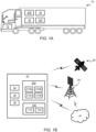
- FIG. 1A is an exemplary schematic side view of a heavy-duty vehicle 10 (hereinafter referred to vehicle 10 for reasons of brevity).
- vehicle 10 comprises a tractor unit 10a which is arranged to tow a trailer unit 10b.
- other heavy-duty vehicles may be employed, e.g., trucks, buses, and construction equipment.
- the vehicle 10 comprises all necessary vehicle units and associated functionality such that it may operate as the skilled person would expect of a vehicle 10, such as a powertrain, chassis, and various control systems. Emphasis in the present disclosure is rather directed at electrical currents of the vehicle 10, and therefore functionality and features related this will be the focus of the present disclosure.
- the vehicle 10 comprises one or more propulsion sources 12.
- the propulsion source 12 may be any suitable propulsion source 12 exemplified by, but not limited to, one or more or a combination of an electrical motor, a combustion engine such as a diesel, gas or gasoline powered engine. At least one propulsion source 12 is an electrical motor.
- the vehicle 10 further comprises at least one energy source 200 suitable for providing energy for the propulsion source(s) 12. That is to say, as at least one propulsion source 12 is an electrical motor, at least one propulsion source 12 is a battery pack 200.
- the vehicle 10 further comprises sensor circuitry 16 arranged to detect, measure, sense or otherwise obtain data relevant for operation of the vehicle 10.
- the data relevant for operation of the vehicle 10 may be exemplified by, but not limited to, one or more of a voltage of the battery pack 200, a current provided by the battery pack 200, a speed of the vehicle 10, a weight of the vehicle 10, an inclination of the vehicle 10, a status (state of charge, fuel level etc.) of the energy source 200 of the vehicle 10 etc.
- the vehicle 10 further comprises communications circuitry 18 configured for communication with, to the vehicle 10, external devices.
- the vehicle 10 further comprises a computer system 100.
- the vehicle 10 may communicate with a cloud server 20 using the communications circuitry 18.
- the communications circuitry 18 may be configured to communicate with the cloud server 20 directly, or via a communications interface such as a cellular communications interface exemplified by a radio base station 30 in FIG. 1B .
- the cloud server 20 may be any suitable cloud server exemplified by, but not limited to, Amazon Web Services (AWS), Microsoft Azure, Google Cloud Platform (GCP), IBM Cloud, Oracle Cloud Infrastructure (OCI), DigitalOcean, Vultr, Linode, Facebook Cloud, Rackspace etc.
- the communications interface is advantageously a wireless communications interface exemplified by, but not limited to, Wi-Fi, Bluetooth, Zigbee, Z-Wave, LoRa, Sigfox, 2G (GSM, CDMA), 3G (UMTS, CDMA2000), 4G (LTE), 5G (NR) etc.
- the vehicle 10 may further, via the communications circuitry 18, be operatively connected to a Global Navigation Satellite System (GNSS) 40 exemplified by, but not limited to, global positioning system (GPS), Globalnaya Navigatsionnaya Sputnikovayassela (GLONASS), Galileo, BeiDou Navigation Satellite System, Navigation with Indian Constellation (NavIC) etc.
- GNSS Global Navigation Satellite System
- GPS Globalnaya Navigatsionnaya Sputnikovaya
- Galileo BeiDou Navigation Satellite System
- the vehicle 10 may be configured to utilize data obtain from the GNSS 40 to determine
- the computer system 100 of the vehicle 10 is advantageously operatively connected to the communications circuitry 18, the sensor circuitry 16, the energy source 200 and/or the propulsion source 12 of the vehicle 10.
- the computer system 100 comprises processing circuitry 110.
- the computer system 100 may comprise a storage device 120, advantageously a non-volatile storage device such as a hard disk drives (HDDs), solid-state drives (SSDs) etc.
- the storage device 120 is operatively connected to the computer system 100.
- a vehicle 10 is an, at least partly, electrically propelled vehicle.
- the vehicle 10 of the present disclosure comprises at least one energy source 200 in the form of an electrical energy source 200, i.e. at least one battery pack 200.
- the vehicle battery pack 200 comprises at least two battery cells 210a, 210b, 210c, 210d.
- the battery pack 200 is shown comprising four battery cells 210a, 210b, 210c, 210d.
- the battery pack 200 may comprise any number of battery cells 210a, 210b, 210c, 210d.
- the battery cells 210a, 210b, 210c, 210d may comprise any number of battery cells 210a, 210b, 210c, 210d.
- the battery pack 200 is advantageously configured to provide energy at least to the propulsion source 12 of the vehicle 10. Additionally, or alternatively, the battery pack 200 may be configured to provide energy to other part components of the vehicle 10 such as, but not limited to, vehicle electronics, climate control of the vehicle 10, safety functions of the vehicle etc.
- a current provided by the battery pack 200 may be advantageous to, as previously indicated, accurately estimate a current provided by the battery pack 200 to the load.
- Accurate current data assists in assessing a health and performance of the battery pack 200.
- charging and discharging patterns may be tracked, abnormal behaviors may be identified, and potential issues like overcharging, undercharging, or excessive discharge (short circuit) may be detected.
- Accurate current measurements enables evaluation of a battery state of charge and state of health of the battery pack 200, ensuring optimal performance and extending battery life.
- Battery packs 200 when used as traction batteries, generally store a significant amount of energy which increases a risk that abnormal behaviors may lead to hazardous conditions, such as overheating, thermal runaway, or electrical failures.
- accurate current measurements aid in optimizing an energy efficiency of the vehicle 10.
- an efficiency of a battery pack 200 may be evaluated and opportunities for improvement may be identified.
- current measurements provide valuable data for performance analysis and diagnostics.
- By analyzing current profiles during various driving conditions and operations it is possible to gain insights into energy usage, power demand, efficiency, etc. of the vehicle 10. This information may assist in diagnosing performance issues, optimizing system configurations, and/or identifying areas for improvement in terms of energy consumption and overall vehicle performance.
- accurate current measurements are generally required for compliance with regulatory standards and industry guidelines. Many standards and regulations set specific limits on battery current for safety and operational reasons. By accurately measuring and documenting the current, it is possible to demonstrate compliance with these standards and ensure the vehicle 10 meets the necessary requirements.
- the inventor behind the present disclosure have identified the importance of current measurements.
- inventive thinking and challenging of the technical prejudice of the present technical field devised an alternative method and system for estimating current to/from a battery pack 200.
- the teachings of the present disclosure may be utilized to ensure accuracy of a prior art battery pack current sensor, to replace a prior art battery pack current sensor, to calibrate a prior art battery pack current sensor etc.
- the importance of the current measurements in batteries causes the skilled person to stay with known prior art battery pack current sensors and provide redundancy by adding further current sensors rather than thinking outside the box and implementing the teachings of the present disclosure.
- the battery pack 200 comprises, as previously indicated, at least two battery cells 210a, 210b, 210c, 210d.
- the battery pack 200 is shown comprising four battery cells 210a, 210b, 210c, 210d.
- the battery cells 210a, 210b, 210c, 210d are connected by inter-cell connectors 230.
- the inter-cell connectors 230 are electrically conducting members exemplified by, but not limited to, one or more or combination of busbars, interconnect cables, cell-to-cell weldings, screws etc.
- the battery pack 200 advantageously comprise a battery pack processing circuitry 220.
- the battery pack processing circuitry 220 may for part of the computer system 100 and the processing circuitry 110 of the computer system 100.
- the battery pack processing circuitry 220 is configured to monitor operation of the battery pack 200.
- the battery pack processing circuitry 220 is operatively connected to (or comprises) one or more battery pack sensor circuitry 240.
- the battery pack sensor circuitry 240 may be configured to measure, sense or otherwise obtain operational data of the battery pack 200.
- the operational data of the battery pack 200 may comprise one or more voltages of the battery pack 200, one or more currents of the battery pack 200, one or more temperatures of the battery pack 200 etc.
- a resistance of the inter-cell connectors 230 is determined/calibrated during manufacturing and/or during design of the battery pack 200.
- the resistance of the inter-cell connectors 230 is advantageously stored in non-volatile storage circuitry (not shown in FIG. 2 or FIG. 3 ) accessible by the computer system 100.
- the battery pack 200 further comprises two or more connectors 231, 232 operatively connected to the battery cells 210a, 210b, 210c, 210d.
- a first connector 231 is operatively connected to a first voltage potential of the battery cells 210a, 210b, 210c, 210d
- a second connector 232 is operatively connected to a second voltage potential of the battery cells 210a, 210b, 210c, 210d.
- the battery pack 200 further comprises a battery pack current sensor 250 configured to detect, measure or otherwise obtain a current provided to or by the two or more connectors 231, 232.
- the inter-cell connectors 230 may be configured to connect the battery cells 210a, 210b, 210c, 210d in series, in parallel or a combination of series or parallel connections.
- the configuration of the inter-cell connectors 230 will depend on a number of battery cells 210a, 210b, 210c, 210d, a capacity of the battery cells 210a, 210b, 210c, 210d, a voltage of the battery cells 210a, 210b, 210c, 210d and a wanted voltage of the battery pack 200.
- the inter-cell connectors 230 connect the battery cells 210a, 210b, 210c, 210d in order to provide a rated capacity from the battery pack 200 and a rated voltage difference between the first potential (a voltage of the first connector 231) and the second potential (a voltage of the second connector 232) of the battery pack 200.
- a rated voltage of the energy source is approximately 800 V.
- the inter-cell connectors 230 are configured to connect the battery cells 210a, 210b, 210c, 210d in parallel. In FIG. 3 , the inter-cell connectors 230 are configured to connect the battery cells 210a, 210b, 210c, 210d in series.
- the battery packs 200 shown in FIG. 2 and FIG. 3 are simplified block diagrams. The skilled person will appreciate that the battery packs 200 advantageously comprise further features such as pre-charge circuitry, fuses etc.
- FIG. 4 a system diagram of a battery pack current estimator 300 is shown.
- the battery pack current estimator 300 is configured to estimate a battery pack current estimate 305.
- the battery pack current estimate 305 is an estimate of a current provided or received by one or more battery packs 200 associated with the battery pack current estimator 300.
- the functions of the battery pack current estimator 300 are advantageously performed by the processing circuitry 110 of the computer system 100 and/or the battery pack processing circuitry 210. It should be mentioned that it may be advantageous to distribute monitoring and supervision of battery cells 210a, 210b, 210c, 210d between dedicated cell supervision circuits, e.g.
- the battery pack current estimator 300 is advantageously configured to receive and/or provide data to the storage device 120 and/or the battery pack current sensor 250.
- the battery pack current estimator 300 comprises an inter-cell voltage drop obtainer 310.
- the inter-cell voltage drop obtainer 310 is configured to obtain voltage drops 312 across a plurality of inter-cell connectors 230.
- An inter-cell voltage drop 312 is a difference in voltage potential between a first connection point and a second connection point interconnected by one or more inter-cell connectors 230.
- the inter-cell voltage drops 312, or voltage drops 312 for short, may be obtained by the previously introduced battery pack sensor circuitry 240.
- An inter-cell voltage drop 312 may be described as associated with the one or more inter-cell connectors 230 across which it is obtained.
- the battery pack current estimator 300 comprises inter-cell connector data 320.
- the battery pack current estimator 300 may be configured to obtain the inter-cell connector data 320 from the storage device 120.
- some inter-cell connecter data 320 is comprised in the battery pack current estimator 300, and some inter-cell connecter data 320 is stored in the storage device 120.
- the inter-cell connector data 320 comprises data describing the inter-cell connectors 230.
- the inter-cell connector data 320 comprises resistance data 322 associated with at least two of the inter-cell connectors 230 of the battery pack 200.
- the resistance data 322 comprises a resistance value describing an electrical resistance of a plurality of inter-cell connectors 230 of the battery pack 200.
- the resistance data 322 may comprise a reactance value describing an electrical reactance of a plurality of inter-cell connector 230 of the battery pack 200.
- the resistance data 322 may be provided as a function of temperature, or compensated based on a temperature of the associated inter-cell connector 230.
- the inter-cell connector data 320 may describe how the inter-cell connectors 230 of the battery pack 200 are connected.
- the inter-cell connector data 320 may describe a type of a plurality of inter-cell connectors 230 of the battery pack 200.
- the inter-cell connector data 320 may describe physical characteristics (length, width, current handling capabilities etc.) of a plurality of inter-cell connectors 230 of the battery pack 200.
- the battery pack current estimator 300 further comprises an inter-cell current determiner 330.
- the inter-cell current determiner 330 is configured to determine a plurality of inter-cell currents 332. Each inter-cell current 332 is determined based on an inter-cell voltage drop 312 of a specific inter-cell connector 230 (or plurality of specific inter-cell connectors 230) together with resistance data 322 of the specific inter-cell connector 230 (or plurality of specific inter-cell connectors 230).
- the inter-cell currents 332 are advantageously determined using Ohm's law.
- the battery pack current estimator 300 further comprises a data processor 340.
- the data processor 340 is configured to process the plurality of inter-cell current 332 and determine the battery pack current estimate 305.
- the data processor 340 may be configured to determine the battery pack current estimate 305 in any suitable way.
- the data processor 340 is configured to determine an inter-cell current average 342 of the plurality of inter-cell current 332.
- the battery pack current estimate 305 may determined by setting the battery pack current estimate 305 to the inter-cell current average 342, or by basing the battery pack current estimate 305 on the inter-cell current average 342.
- the inter-cell current average 342 is an arithmetic mean of the plurality of inter-cell current 332.
- the inter-cell current average 342 is a geometric mean of the plurality of inter-cell current 332.
- the data processor 340 may be configured to determine an inter-cell current estimate standard deviation 343 of the inter-cell current average 342.
- the data processor 340 may be configured to determine a delta current indicator 344.
- the delta current indicator 344 indicate a difference in current between a battery pack current 251 sensed by the battery pack current sensor 250 and the battery pack current estimate 305.
- the delta current indicator 344 may consequently be determined by comparison of the battery pack current 251 to the battery pack current estimate 305.
- the data processor 340 may be configured to determine a delta current shift 345.
- the delta current shift 345 indicate a shift in delta current indicator 344 and may be obtained by comparing a current delta current indicator 344 to one or more previous delta current indicators 344.
- the delta current shift 345 is determined by comparison of the current delta current indicator 344 to a sliding delta current indicator average provided as a sliding average of a plurality of previous delta current indicators 344.
- the battery pack current estimate 305 By determining the battery pack current estimate 305 as the mean of a plurality of inter-cell currents 332, the battery pack current estimates 305 will tend towards a normal distribution, even if the inter-cell currents 332 themselves are not normally distributed. This is known as the central limit theorem. Further to this, by the law of large numbers, the battery pack current estimate 305 converges to the true mean (expected value) of the inter-cell currents 332. As the skilled person understands, this is under assumption that no common offset in the inter-cell currents 332 and that e.g. AD converters provide sufficient resolution. This means that by combining several different, advantageously independent, measurements of the same true battery pack current, the battery pack current estimate 305 may provide a more accurate measure of the true battery pack current than the battery pack current sensor 250 as the number of inter-cell currents 332 increases.
- the battery pack current estimator 300 comprises an optional current sensor calibrator 350.
- the current sensor calibrator 350 is configured to monitor data of the battery pack current estimator 300 and determine if the battery pack current sensor 250 is functioning correctly. To this end, the current sensor calibrator 350 may be configured to compare the delta current indicator 344 to a permissible error range 344'. If the delta current indicator 344 is outside the permissible error range 344' the current sensor calibrator 350 may be configured to determine that the battery pack current sensor 250 is malfunctioning.
- the permissible error range 344' may be a constant predetermined range, a range defined by a percentage of a current delta current indicator 344 or a combination of the two.
- the current sensor calibrator 350 may be configured to compare the delta current shift 345 to a permissible deviation range 345'. If the delta current shift 345 is outside the permissible deviation range 345', the current sensor calibrator 350 may be configured to determine that the battery pack current sensor 250 is malfunctioning.
- the permissible deviation range 345' may be a constant predetermined range, a range defined by a percentage of a current delta current shift 345 or a combination of the two.
- the current sensor calibrator 350 is advantageously configured to send an indication of current sensor malfunction to the computer system 100, if the current sensor calibrator 350 determines that the battery pack current sensor 250 is malfunctioning. Additionally, or alternatively, the current sensor calibrator 350 may be configured to calibrate, offset, compensate or otherwise control the battery pack current sensor 250 and/or the battery pack current 251 based on the battery pack current estimate 305 and/or any other data from the data processor 340.
- battery pack current estimator 300 comprises an inter-cell connector calibrator 360.
- the inter-cell connector calibrator 360 may be configured to update resistance data 322 of one or more specific inter-cell connector 230 (or plurality of specific inter-cell connectors 230) based on their associated inter cell voltage drops 312 and the battery pack current estimate 305.
- the resistance data 322 may be updated by setting the resistance data 322 to a resistance value calculated based on the inter cell voltage drop 312 and the battery pack current estimate 305.
- the resistance data 322 may be updated by weighting the resistance data 322 with the resistance value calculated based on the inter cell voltage drop 312 and the battery pack current estimate 305.
- the resistance data 322 may be updated by weighting the resistance data 322 with the resistance value calculated based on the inter cell voltage drop 312 and the battery pack current estimate 305.
- the weighting may be any suitable weighting, an average etc.
- the inter-cell connector calibrator 360 may be configured to update resistance data 322 correspondingly based on the battery pack current 251.
- the battery pack current 251 and/or inter cell voltage drop 312 utilized for updating the resistance data 322 may be an average of a plurality of previous battery pack currents 251 and/or inter cell voltage drops 312, i.e. time series data of inter-cell voltage drops 312 and/or battery pack currents 251. Updating of the resistance data 322 is advantageous as it allows the resistance data 322 to be updated and corrected in case of e.g. ageing, damages, etc. of the associated inter-cell connector 230.
- the inter-cell connector calibrator 360 may be configured to compare the inter-cell current average 342 to a confidence interval 342' of the inter cell current average 342.
- the confidence interval 342' may be a predefined confidence interval defined as e.g. a percentage, and/or the confidence interval 342' may be defined based on the standard deviation 343 of the inter-cell current average 342.
- the confidence interval 342' may be defined as the standard deviation 343 plus/minus four times the standard deviation 343 of the inter-cell current average 342.
- the confidence interval 342' may be defined as the standard deviation 343 plus/minus five times the standard deviation 343 of the inter-cell current average 342.
- the confidence interval 342' may be defined as the standard deviation 343 plus/minus six times the standard deviation 343 of the inter-cell current average 342.
- the inter-cell connector calibrator 360 may be configured to determine that any inter cell connectors 230 exhibiting an inter-cell current 332 being outside the confidence interval 342' of the inter-cell current average 342 are malfunctioning.
- the inter-cell connector calibrator 360 is configured to send an indication of inter-cell connection malfunction to the computer system 100, if the current sensor calibrator 350 determines that one or more inter-cell connectors 230 are malfunctioning.
- the inter-cell connector calibrator 360 may be configured to identify inter-cell connector 230 determined to be malfunctioning and the inter cell current determiner 330 may be configured to exclude inter-cell voltages 312 associated with the malfunctioning inter-cell connectors 230 from consecutive estimations of battery back current estimate 305.
- battery pack current estimator 300 comprises a current controller 370.
- the current controller 370 may be configured to determine if power (current) should be transfer to from the battery pack 200 at any given point in time. Generally, a battery pack 200 prevent further power going into or being provided by the battery pack 200 if the battery back current 251 was outside an permissible battery current range 251'. However, in the battery pack current estimator 300 of the present disclosure, the current controller 370 may be configured to permit further transfer of power to/from the battery pack 200 even if the battery pack current 251 sensed by the current sensor 250 is outside the permissible battery current range 251'.
- the current controller 370 is configured to prevent further power transfer to/from the battery pack 200 if both the battery pack current estimate 305 and the battery pack current 251 are outside the battery current range 251'. That is to say, the current controller 370 may be configured to permit further power transfer to/from the battery pack 200 if the battery pack current estimate 305 is inside the battery pack current range 251' and the battery pack current 251 is outside the battery current range 251'. In some examples, the current controller 370 may be configured to permit further power transfer to/from the battery pack 200 if the battery pack current estimate 305 is outside the battery pack current range 251' and the battery pack current 251 is inside the battery current range 251'.
- the current controller 370 may be configured to permit further power transfer to/from the battery pack 200 if the current sensor 250 is determined to be malfunctioning. In some examples, the current controller 370 may be configured to permit further power transfer to/from the battery pack 200 if the battery pack current estimate 305 is inside the battery pack current range 251' and the current sensor 250 is determined to be malfunctioning. In some examples, the current controller 370 may be configured to permit further power transfer to/from the battery pack 200 at a limited rate if the current sensor 250 is determined to be malfunctioning.
- a battery pack 200 suitable for a vehicle 10 will comprise more than 5000 battery cells 210, and well over 9000 battery cells 210 is also commonplace. Each of these cells are connected by a respective inter-cell connector 230 making their associated set of inter-cell voltages 312 well within the range of what may be considered a normal distribution.
- a group of battery cells 210 is generally connected in parallel (by inter-cell connectors 230) to form what may be referred to as a logical cell.
- a plurality of logical cells are generally connected in series (by inter-cell connectors 230) and generally voltages between each of these logic cells is monitored by e.g. the battery pack processing circuitry 220.
- a vehicle 10 generally comprise 100-200 logical cells with inter-cell connectors 230 which also provide a sufficiently large sample size for assuming their averages being normally distributed.
- not all battery cells 210 are placed in parallel, but generally sets of battery cells 210 are arranged in parallel to obtain a wanted capacitance of the battery pack 200 and these sets are arranged in series to obtain a wanted voltage of the battery pack 200. This will be detailed with a simplified example in FIG. 5A and FIG. 5B .
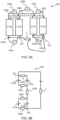
- FIG. 5A an exemplary schematic view of a partial battery pack 200 is shown.
- the battery pack 200 comprises a first battery cell 210a, a second battery cell 210b, a third battery cell 210c and a fourth battery cell 210d.
- the first battery cell 210a and the second battery cell 210b are connected in parallel by a first inter-cell connector 230a and a fourth inter-cell connector 230d.
- the third battery cell 210c and the fourth battery cell 210d are connected in parallel by a third inter-cell connector 230c and a fifth inter-cell connector 230e.
- the parallel arrangement of the first battery cell 210a and the second battery cell 210b is connected in series with the parallel arrangement of the third battery cell 210c and the fourth battery cell 210d by a second inter-cell connector 230b.
- the first connector 231 is operatively connector to the fifth inter-cell connector 230e.
- the second connector 232 is operatively connector to the fourth inter-cell connector 230d.
- An exemplary load L is connected between the first connector 231 and the second connector 232.
- a plurality of sensor circuits 240a, 240b, 240c, 240d, 240e are provided to sense inter-cell voltage drops 312 of their respective inter-cell connector 230a, 230b, 230c, 230d, 230e.
- FIG. 5A a plurality of sensor circuits 240a, 240b, 240c, 240d, 240e are provided to sense inter-cell voltage drops 312 of their respective inter-cell connector 230a, 230b, 230c,
- a first sensor circuit 240a is arranged to sense an inter-cell voltage drop across the first inter-cell connector 230a
- a second sensor circuit 240b is arranged to sense an inter-cell voltage drop across the second inter-cell connector 230b
- a third sensor circuit 240c is arranged to sense an inter-cell voltage drop across the third inter-cell connector 230c
- an inter-cell fourth sensor circuit 240d is arranged to sense a voltage drop across the fourth inter-cell connector 230d
- a fifth sensor circuit 240e is arranged to sense an inter-cell voltage drop across the fifth inter-cell connector 230e.
- a specific sensor circuit 240a, 240b, 240c, 240d, 240e, 240f may be configured to selectively sense voltage drops of more than one inter-cell connector 230a, 230b, 230c, 230d, 230e, 230f.
- a specific sensor circuit 240a, 240b, 240c, 240d, 240e, 240f may be configured to sense a voltage drop of two or more inter-cell connector 230a, 230b, 230c, 230d, 230e, 230f in series.
- FIG. 5B a schematic of the battery pack 200 of FIG. 5A is shown.
- a current I is provided from the battery pack 200 to the load L.
- the current I is equal to an inter-cell current 332 through the second inter-cell connector 230b.
- the current I is also equal to a sum of the inter-cell currents 332 through the third inter-cell connector 230c and the fifth inter-cell connector 230e.
- the current I is also equal to a sum of the inter-cell currents 332 through the first inter-cell connector 230a and the second inter-cell connector 230d.
- the current I through the load L may be determined by combinations of inter-cell currents 332 and must not be determined directly from a resistance data 322 and inter-cell voltage 312 of a respective inter-cell connector 230.
- a method 400 for providing a current estimate 305 of a our from, or into, a battery pack 200 is advantageously a computer implemented method that may be performed by the computer system 100 presented herein, specifically by processing circuitry 110 of the computer system 100.
- the processing circuitry 110 of the computer system 100 may be configured to cause execution of the method 400 rather than executing the method 400 itself.
- the method 400 should not be considered limited to the features presented in reference to FIG. 6 , but may advantageously be expanded to comprise any feature, function or example described in the present disclosure, specifically those described in reference to FIG. 4 .
- the method 400 comprises obtaining 410 resistance data 322 of a plurality of inter-cell connectors 230 of the battery pack 200. This may comprise, as previously indicated, reading resistance data 322, or inter-cell connector data 320, from a storage device 120.
- the method 400 further comprises obtaining 420 inter-cell voltage drops 312 across the plurality of inter-cell connectors 230. This may, as previously described, be achieved by configuring one or more battery pack sensor circuitry 240 to measure, sense or otherwise obtain the inter-cell voltage drops 312.
- the method 400 further comprises determining 430 inter-cell currents 332 based on the resistance data 322 and associated inter-cell voltage drops 312. This may, as previously described, be achieved by calculation using Ohm's law.
- the method 400 further comprises determining 450 the battery pack current estimate 305 an estimate of the battery pack current 251 based on the inter-cell currents 332. This may be achieved by e.g. setting the estimate of the pack currents 305 to one of the inter-cell currents 332.
- the method 400 may comprise processing 440 of the inter-cell currents 332.
- the processing 440 may, as previously indicated, be performed in a number of different ways.
- the processing 440 comprises determining 442 the inter-cell current average 342 of the inter-cell currents 332.
- the inter-cell current average 342 may, as previously described, be e.g. an arithmetic mean, a geometric mean etc.
- the processing 440 may further comprise determining 444 the inter-cell current estimate standard deviation 343 of the inter-cell current average 342.
- the processing 440 may comprise determining 446 the delta current indicator 344.
- the delta current indicator 344 is advantageously determined by comparison of the battery pack current 251 and the battery pack current estimate 305.
- the method 400 may comprise obtaining 405 the battery pack current 251, advantageously from the current sensor 250 of the battery pack 200.
- the determining 450 of the current estimate advantageously utilizes one or more of the inter-cell current average 342, the inter-cell current estimate standard deviation 343 and/or the delta current indicator 344 in determining the battery pack current estimate 305.
- the method may comprise, as previously described, determining 460 that the batter pack current sensor 250 and/or one or more inter-cell connectors 230 are malfunctioning based on e.g. the inter-cell current average 342, the inter-cell current estimate standard deviation 343 and/or the delta current indicator 344.
- the method 400 may comprise, as previously described updating 470 the resistance data 322 and/or the inter-cell connector data 320 based on one or more of the inter-cell voltage drops 312, the inter-cell currents 332, the inter-cell current average 342, the inter-cell current estimate standard deviation 343, the delta current indicator 344, etc.
- the method 400 may comprise calibrating (not shown), the battery pack current sensor 250 based on one or more of the inter-cell voltage drops 312, the inter-cell currents 332, the inter-cell current average 342, the inter-cell current estimate standard deviation 343, the delta current indicator 344, etc.
- the computer program product 500 comprises a computer program 600 and a non-transitory computer readable medium 700.
- the computer program 600 is advantageously stored on the computer readable medium 700.
- the computer readable medium 700 is, in FIG. 7 , exemplified as a vintage 5,25" floppy disc, but may be embodied as any suitable non-transitory computer readable medium such as, but not limited to, hard disk drives (HDDs), solid-state drives (SSDs), optical discs (e.g., CD-ROM, DVD-ROM, CD-RW, DVD-RW), USB flash drives, magnetic tapes, memory cards, Read-Only Memories (ROM), network-attached storage (NAS), cloud storage etc.
- HDDs hard disk drives
- SSDs solid-state drives
- optical discs e.g., CD-ROM, DVD-ROM, CD-RW, DVD-RW
- USB flash drives magnetic tapes
- memory cards Read-Only Memories (ROM), network-attached storage (NAS), cloud
- the computer program 600 comprises instruction 610 e.g. program instruction, software code, that, when executed by processing circuitry cause the processing circuitry to perform the method 400 described herein with reference to FIG. 6 .
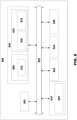
- FIG. 8 is a schematic diagram of a computer system 800 for implementing examples disclosed herein.
- the computer system 800 may be the computer system 100 introduced with reference to FIG. 1A .
- the computer system 800 is adapted to execute instructions from a computer-readable medium to perform these and/or any of the functions or processing described herein.
- the computer system 800 may be connected (e.g., networked) to other machines in a LAN, an intranet, an extranet, or the Internet. While only a single device is illustrated, the computer system 800 may include any collection of devices that individually or jointly execute a set (or multiple sets) of instructions to perform any one or more of the methodologies discussed herein.
- any reference in the disclosure and/or claims to a computer system, computing system, computer device, computing device, control system, control unit, electronic control unit (ECU), processor device, processing circuitry, etc. includes reference to one or more such devices to individually or jointly execute a set (or multiple sets) of instructions to perform any one or more of the methodologies discussed herein.
- control system may include a single control unit or a plurality of control units connected or otherwise communicatively coupled to each other, such that any performed function may be distributed between the control units as desired.
- such devices may communicate with each other or other devices by various system architectures, such as directly or via a Controller Area Network (CAN) bus, etc.
- CAN Controller Area Network
- the computer system 800 may comprise at least one computing device or electronic device capable of including firmware, hardware, and/or executing software instructions to implement the functionality described herein.
- the computer system 800 may include processing circuitry 802 (e.g., processing circuitry including one or more processor devices or control units), a memory 804, and a system bus 806.
- the processing circuitry 802 may be, or comprise, the processing circuitry 110 introduced with reference to FIG. 1B .
- the computer system 800 may include at least one computing device having the processing circuitry 802.
- the system bus 806 provides an interface for system components including, but not limited to, the memory 804 and the processing circuitry 802.
- the processing circuitry 802 may include any number of hardware components for conducting data or signal processing or for executing computer code stored in memory 804.
- the processing circuitry 802 may, for example, include a general-purpose processor, an application specific processor, a Digital Signal Processor (DSP), an Application Specific Integrated Circuit (ASIC), a Field Programmable Gate Array (FPGA), a circuit containing processing components, a group of distributed processing components, a group of distributed computers configured for processing, or other programmable logic device, discrete gate or transistor logic, discrete hardware components, or any combination thereof designed to perform the functions described herein.
- the processing circuitry 802 may further include computer executable code that controls operation of the programmable device.
- the system bus 806 may be any of several types of bus structures that may further interconnect to a memory bus (with or without a memory controller), a peripheral bus, and/or a local bus using any of a variety of bus architectures.
- the memory 804 may be one or more devices for storing data and/or computer code for completing or facilitating methods described herein.
- the memory 804 may include database components, object code components, script components, or other types of information structure for supporting the various activities herein. Any distributed or local memory device may be utilized with the systems and methods of this description.
- the memory 804 may be communicably connected to the processing circuitry 802 (e.g., via a circuit or any other wired, wireless, or network connection) and may include computer code for executing one or more processes described herein.
- the memory 804 may include non-volatile memory 808 (e.g., read-only memory (ROM), erasable programmable read-only memory (EPROM), electrically erasable programmable read-only memory (EEPROM), etc.), and volatile memory 810 (e.g., random-access memory (RAM)), or any other medium which can be used to carry or store desired program code in the form of machine-executable instructions or data structures and which can be accessed by a computer or other machine with processing circuitry 802.
- a basic input/output system (BIOS) 812 may be stored in the non-volatile memory 808 and can include the basic routines that help to transfer information between elements within the computer system 800.
- BIOS basic input/output system
- the computer system 800 may further include or be coupled to a non-transitory computer-readable storage medium such as the storage device 814, which may comprise, for example, an internal or external hard disk drive (HDD) (e.g., enhanced integrated drive electronics (EIDE) or serial advanced technology attachment (SATA)), HDD (e.g., EIDE or SATA) for storage, flash memory, or the like.
- HDD enhanced integrated drive electronics
- SATA serial advanced technology attachment
- the storage device 814 and other drives associated with computer-readable media and computer-usable media may provide non-volatile storage of data, data structures, computer-executable instructions, and the like.
- Computer-code which is hard or soft coded may be provided in the form of one or more modules.
- the module(s) can be implemented as software and/or hard-coded in circuitry to implement the functionality described herein in whole or in part.
- the modules may be stored in the storage device 814 and/or in the volatile memory 810, which may include an operating system 816 and/or one or more program modules 818.
- All or a portion of the examples disclosed herein may be implemented as a computer program 820 stored on a transitory or non-transitory computer-usable or computer-readable storage medium (e.g., single medium or multiple media), such as the storage device 814, which includes complex programming instructions (e.g., complex computer-readable program code) to cause the processing circuitry 802 to carry out actions described herein.
- the computer-readable program code of the computer program 820 can comprise software instructions for implementing the functionality of the examples described herein when executed by the processing circuitry 802.
- the storage device 814 may be a computer program product (e.g., readable storage medium) storing the computer program 820 thereon, where at least a portion of a computer program 820 may be loadable (e.g., into a processor) for implementing the functionality of the examples described herein when executed by the processing circuitry 802.
- the processing circuitry 802 may serve as a controller or control system for the computer system 800 that is to implement the functionality described herein.
- the computer system 800 may include an input device interface 822 configured to receive input and selections to be communicated to the computer system 800 when executing instructions, such as from a keyboard, mouse, touch-sensitive surface, etc. Such input devices may be connected to the processing circuitry 802 through the input device interface 822 coupled to the system bus 806 but can be connected through other interfaces, such as a parallel port, an Institute of Electrical and Electronic Engineers (IEEE) 1394 serial port, a Universal Serial Bus (USB) port, an IR interface, and the like.
- the computer system 800 may include an output device interface 824 configured to forward output, such as to a display, a video display unit (e.g., a liquid crystal display (LCD) or a cathode ray tube (CRT)).
- the computer system 800 may include a communications interface 826 suitable for communicating with a network as appropriate or desired.
- Example 1 A computer system 100 comprising processing circuitry 110 configured to: obtain resistance data 322 of a plurality of inter-cell connectors 230 of a battery pack 200 comprising a plurality of battery cells 210 a, 210 b, 210 c, 210 d, obtain inter-cell voltage drops 312 across the plurality of inter-cell connectors 230, determine inter-cell currents 332 based on the resistance data 322 and associated inter-cell voltage drops 312, and determine a battery pack current estimate 305 of a battery pack current 251 of the battery pack 200 based on the inter-cell currents 332.
- Example 2 The computer system 100 of example 1, wherein the processing circuitry 110 is further configured to: determine an inter-cell current average 342 as a mean of the inter-cell currents 332, and determine the battery pack current estimate 305 based on the inter-cell current average 342.
- Example 3 The computer system 100 of example 2, wherein the processing circuitry 110 is further configured to: determine an inter-cell current estimate standard deviation 343 as a standard deviation of the inter-cell current average 342, for each inter-cell connector 230 exhibiting an inter-cell current being outside a predefined confidence interval 342' of the inter-cell current average 342, determine that the inter-cell connector 230 is malfunctioning.
- Example 4 The computer system 100 of example 2 or 3, wherein the processing circuitry 110 is further configured to: determining the average of inter-cell current average 342 as an arithmetic mean of the inter-cell currents 332.
- Example 5 The computer system 100 of example 2 or 3, wherein the processing circuitry 110 is further configured to: determining the inter-cell current average 342 as a geometric mean of the inter-cell currents 332.
- Example 6 The computer system 100 of any one of examples 1 to 5, wherein the processing circuitry 110 is further configured to: obtain, from a battery pack current sensor 250, a battery pack current 251 of the battery pack 200, determine a delta current indicator 344 by comparison of the battery pack current 251 and the battery pack current estimate 305, and responsive to the delta current indicator 344 being outside a permissible error range 344', determining that the battery pack current sensor 250 is malfunctioning.
- Example 7 The computer system 100 of example 6, wherein the processing circuitry 110 is further configured to: determine a delta current shift 345 by comparison of the delta current indicator 344 with one or more previous delta current indicators 344, and responsive to the delta current shift 345 being outside a permissible deviation range 345', determining that the battery pack current sensor 250 is malfunctioning.
- Example 8 The computer system 100 of example 7, wherein the processing circuitry 110 is further configured to: determine the delta current shift 345 by a comparison of the delta current indicator 344 with a sliding delta current indicator average of a plurality previous delta current indicators 344.
- Example 9 The computer system 100 of any one of examples 6 to 8, wherein the processing circuitry 110 is further configured to: responsive to determining that the battery pack current sensor 250 is malfunctioning, determine that further transfer of power to/from the battery pack 200 is allowed based on the battery pack current estimate 305.
- Example 10 The computer system 100 of any one of examples 1 to 9, wherein the processing circuitry 110 is further configured to: update the resistance data 322 of one or more of the plurality of inter-cell connectors 230 based on the battery pack current estimate 305 and inter-cell voltage drops 312 across the plurality of inter-cell connectors 230, and/or time series data of inter-cell voltage drops 312 across the plurality of inter-cell connectors 230.
- Example 11 The computer system 100 of any one of examples 6 to 10, wherein the processing circuitry 110 is further configured to: update the resistance data 322 based on the battery pack current 251.
- Example 12 The computer system 100 of any one of examples 3 to 11, wherein the processing circuitry 110 is further configured to: exclude inter-cell currents associated with an inter-cell connector 230 determined to be malfunctioning from determining of a subsequent battery pack current estimate 305.
- Example 13 The computer system 100 of example 1, wherein the processing circuitry 110 is further configured to: determine an inter-cell current average 342 as a mean of the inter-cell currents 332, and determine the battery pack current estimate 305 based on the inter-cell current average 342; determine an inter-cell current estimate standard deviation 343 as a standard deviation of the inter-cell current average 342, for each inter-cell connector 230 exhibiting an inter-cell current being outside a predefined confidence interval 342' of the inter-cell current average 342, determine that the inter-cell connector 230 is malfunctioning; determine the average of inter-cell current average 342 as an arithmetic mean of the inter-cell currents 332 or determine the inter-cell current average 342 as a geometric mean of the inter-cell currents 332; obtain, from a battery pack current sensor 250, a battery pack current 251 of the battery pack current 251, determine a delta current indicator 344 by comparison of the battery pack current 251 and the battery pack current estimate 305, and responsive to the delta current indicator 344 being outside a
- Example 14 A vehicle 10 comprising an electric propulsion source , a battery pack 200 operatively connected to the computer system 100 of any one of examples 1 to 13 and configured to provide power to the electric propulsion source.
- Example 15 The vehicle 10 of example 14, wherein the vehicle 10 is a heavy-duty vehicle 10.
- Example 16 A computer implemented method 400 comprising: obtaining 410, by a processing circuitry of a computer system 100, resistance data 322 of a plurality of inter-cell connectors 230 of a battery pack 200 comprising a plurality of battery cells 210 a, 210 b, 210 c, 210 d, obtaining 420, by the processing circuitry of the computer system 100, inter-cell voltage drops 312 across the plurality of inter-cell connectors 230, determining 430, by the processing circuitry of the computer system 100, inter-cell currents 332 based on the resistance data 322 and associated inter-cell voltage drops 312, and determining 450, by the processing circuitry of the computer system 100, a battery pack current estimate 305 of a battery pack current 251 of the battery pack 200 based on the inter-cell currents 332.
- Example 17 The computer implemented method 400 of example 16, further comprising: determining 442, by the processing circuitry of the computer system 100, an inter-cell current average 342 as a mean of the inter-cell currents 332, and determining 450, by the processing circuitry of the computer system 100, the battery pack current estimate 305 based on the inter-cell current average 342.
- Example 18 The computer implemented method 400 of example 17, further comprising: determining 444, by the processing circuitry of the computer system 100, an inter-cell current estimate standard deviation 343 as a standard deviation of the inter-cell current average 342, for each inter-cell connector 230 exhibiting an inter-cell current 332 being outside a predefined confidence interval 342' of the inter-cell current average 342, determining, by the processing circuitry of the computer system 100, that the inter-cell connector 230 is malfunctioning.
- Example 19 The computer implemented method 400 of example 18 or 19 further comprising: determining 442, by the processing circuitry of the computer system 100, the average of the inter-cell current average 342 as as an arithmetic mean of the inter-cell currents 332.
- Example 20 The computer implemented method 400 of example 17 or 18 further comprising: determining 442, by the processing circuitry of the computer system 100, the average of the inter-cell current average 342 as a geometric mean of the inter-cell currents 332.
- Example 21 The computer implemented method 400 of any one of examples 16 to 20 further comprising: obtaining 405, by the processing circuitry of the computer system 100, from a battery pack current sensor 250, a battery pack current 251 of the battery pack current 251, determining 446, by the processing circuitry of the computer system 100, a delta current indicator 344 by comparison of the battery pack current 251 and the battery pack current estimate 305, and responsive to the delta current indicator 344 being outside a permissible error range 344', determining 460, by the processing circuitry of the computer system 100, that the battery pack current sensor 250 is malfunctioning.
- Example 22 The computer implemented method 400 of example 21 further comprising: determining 446, by the processing circuitry of the computer system 100, a delta current shift 345 by comparison of the delta current indicator 344 with one or more previous delta current indicators 344, and responsive to the delta current shift 345 being outside a permissible deviation range 345', determining 460, by the processing circuitry of the computer system 100, that the battery pack current sensor 250 is malfunctioning.
- Example 23 The computer implemented method 400 of example 22 further comprising: determining 446, by the processing circuitry of the computer system 100, the delta current shift 345 by a comparison of the delta current indicator 344 with a sliding delta current indicator average of a plurality previous delta current indicators 344.
- Example 24 The computer implemented method 400 of any one of examples 21 to 23 further comprising: responsive to determining that the battery pack current sensor 250 is malfunctioning, determining, by the processing circuitry of the computer system 100, that further transfer of power to/from the battery pack 200 is allowed based on the battery pack current estimate 305.
- Example 25 The computer implemented method 400 of any one of examples 16 to 24 further comprising: updating 470, by the processing circuitry of the computer system 100, the resistance data 322 of one or more of the plurality of inter-cell connectors 230 based on the battery pack current estimate 305 and inter-cell voltage drops 312 across the plurality of inter-cell connectors 230, and/or time series data of inter-cell voltage drops 312 across the plurality of inter-cell connectors 230.
- Example 26 The computer implemented method 400 of any one of examples 16 to 25, further comprising: updating 470, by the processing circuitry of the computer system 100, the resistance data 322 based on the battery pack current 251.
- Example 27 The computer implemented method 400 of any one of examples 16 to 26, further comprising: excluding, by the processing circuitry of the computer system 100, inter-cell currents associated with an inter-cell connector 230 determined to be malfunctioning from determining of a subsequent battery pack current estimate 305.
- Example 28 A computer program product comprising program code for performing, when executed by the processing circuitry, the method of any of examples 16 to 27.
- Example 29 A non-transitory computer-readable storage medium comprising instructions, which when executed by the processing circuitry, cause the processing circuitry to perform the method of any of examples 16 to 27.
- Relative terms such as “below” or “above” or “upper” or “lower” or “horizontal” or “vertical” may be used herein to describe a relationship of one element to another element as illustrated in the Figures. It will be understood that these terms and those discussed above are intended to encompass different orientations of the device in addition to the orientation depicted in the Figures. It will be understood that when an element is referred to as being “connected” or “coupled” to another element, it can be directly connected or coupled to the other element, or intervening elements may be present. In contrast, when an element is referred to as being “directly connected” or “directly coupled” to another element, there are no intervening elements present.
Landscapes
- Physics & Mathematics (AREA)
- General Physics & Mathematics (AREA)
- Chemical & Material Sciences (AREA)
- Chemical Kinetics & Catalysis (AREA)
- Electrochemistry (AREA)
- General Chemical & Material Sciences (AREA)
- Engineering & Computer Science (AREA)
- Manufacturing & Machinery (AREA)
- Power Engineering (AREA)
- Secondary Cells (AREA)
- Charge And Discharge Circuits For Batteries Or The Like (AREA)
Abstract
A computer system (100) comprising processing circuitry (110) is presented. The processing circuitry (110) is configured to obtain resistance data of a plurality of inter-cell connectors (230) of a battery pack (200) comprising a plurality of battery cells (210a, 210b, 210c, 210d), and obtain inter-cell voltage drops across the plurality of inter-cell connectors (230). The processing circuitry (110) is further configured to determine inter-cell currents based on the resistance data and associated inter-cell voltage drops; and determine a battery pack current estimate of a battery pack current of the battery pack (200) based on the inter-cell currents.
Description
- The disclosure relates generally to power control. In particular aspects, the disclosure relates to battery current estimation. The disclosure can be applied marine vessels, industrial applications and vehicles, specifically heavy-duty vehicles, such as trucks, buses, and construction equipment, among other vehicle types. Although the disclosure may be described with respect to a particular vehicle, the disclosure is not restricted to any particular vehicle.
- Any battery power system or device will generally benefit from estimating a current provided by the battery. The current from the battery (or to the battery during charging) will, in addition to providing an indication of a power consumption of the system or device, further indicate any potential problems indicted by an unexpectedly high or low current.
- Generally, in electrically propelled vehicles, current sensors are provided to monitor and detect current going into the traction battery and currents provided by the traction battery. In response to detection of abnormal currents, it is not uncommon for computer systems of the vehicle to be configured to (temporarily) prevent current transfer to/from the battery. To this end, high integrity and reliability in current measurement is important. The high integrity and reliability is advantageous in order to e.g. not damage battery cells by charging with too high currents due to incorrect current reading, or not to erroneously detect too high currents causing an unwanted stop of the usage of the batteries.
- According to a first aspect of the disclosure, a computer system comprising processing circuitry is presented. The processing circuitry is configured to obtain resistance data of a plurality of inter-cell connectors of a battery pack comprising a plurality of battery cells and obtain inter-cell voltage drops across the plurality of inter-cell connectors. The processing circuitry is further configured to determine inter-cell currents based on the resistance data and associated inter-cell voltage drops, and determine a battery pack current estimate of a battery pack current of the battery pack based on the inter-cell currents.. The first aspect of the disclosure may seek to increase the accuracy, integrity and/or reliability of current measurements provided by a current sensor of a battery pack. A technical benefit may include reduced risk of erroneous measurements of currents, cheaper battery pack as the current sensor may be omitted. A technical benefit may include that basing the estimate on a plurality a currents cause the estimate to converge to a normal distribution by the central limiting theorem.
- Optionally in some examples, including in at least one preferred example, the processing circuitry is further configured to determine an inter-cell current average as a mean of the inter-cell currents, and determine the battery pack current estimate based on the inter-cell current average. A technical benefit may include averaging a plurality a currents causing their mean to converge to the true mean of the current by the central limiting theorem and law of large numbers.
- Optionally in some examples, including in at least one preferred example, the processing circuitry is further configured to determine an inter-cell current estimate standard deviation as a standard deviation of the inter-cell current average and, for each inter-cell connector exhibiting an inter-cell current being outside a predefined confidence interval of the inter-cell current average, determine that the inter-cell connector is malfunctioning. A technical benefit may include detecting that there is a potential issue with an inter-cell connector, or a sensor associated with that inter-cell connector.
- Optionally in some examples, including in at least one preferred example, the processing circuitry is further configured to obtain, from a battery pack current sensor, a battery pack current of the battery pack current and determine a delta current indicator by comparison of the battery pack current and the battery pack current estimate. The processing circuitry is further configured to, responsive to the delta current indicator being outside a permissible error range, determining that the battery pack current sensor is malfunctioning. A technical benefit may include detecting that there is a problem with the battery pack current sensor.
- Optionally in some examples, including in at least one preferred example, the processing circuitry is further configured to determine a delta current shift by comparison of the delta current indicator with one or more previous delta current indicators, and responsive to the delta current shift being outside a permissible deviation range, determining that the battery pack current sensor is malfunctioning. A technical benefit may include detecting that there is a problem with the battery pack current sensor.
- Optionally in some examples, including in at least one preferred example, the processing circuitry is further configured to, responsive to determining that the battery pack current sensor is malfunctioning, determine that further transfer of power to/from the battery pack is allowed based on the battery pack current estimate. A technical benefit may include allowing the battery back to continue to provide power to a load regardless of the malfunctioning battery pack current sensor as accurate current estimations are provided by the battery pack current estimate.
- Optionally in some examples, including in at least one preferred example, the processing circuitry is further configured to update the resistance data of one or more of the plurality of inter-cell connectors based on the battery pack current estimate and inter-cell voltage drops across the plurality of inter-cell connectors. A technical benefit may include ensuring that the resistance data is correct and compensate for ageing, wear etc. of the inter-cell connectors.
- Optionally in some examples, including in at least one preferred example, the processing circuitry is further configured to update the resistance data of one or more of the plurality of inter-cell connectors based on time series data of inter-cell voltage drops across the plurality of inter-cell connectors. A technical benefit may include ensuring that the resistance data is correct and compensate for ageing, wear etc. of the inter-cell connectors.
- Optionally in some examples, including in at least one preferred example, the processing circuitry is further configured to update the resistance data of one or more of the plurality of inter-cell connectors based on a battery pack current obtained from a battery pack current sensor of the battery pack. A technical benefit may include ensuring that the resistance data is correct and compensate for ageing, wear etc. of the inter-cell connectors.
- Optionally in some examples, including in at least one preferred example, the processing circuitry is further configured to determine an inter-cell current average as a mean of the inter-cell currents, and determine the battery pack current estimate based on the inter-cell current average; determine an inter-cell current estimate standard deviation as a standard deviation of the inter-cell current average, for each inter-cell connector exhibiting an inter-cell current being outside a predefined confidence interval of the inter-cell current average, determine that the inter-cell connector is malfunctioning; obtain, from a battery pack current sensor, a battery pack current of the battery pack current, determine a delta current indicator by comparison of the battery pack current and the battery pack current estimate, and responsive to the delta current indicator being outside a permissible error range, determining that the battery pack current sensor is malfunctioning; responsive to determining that the battery pack current sensor is malfunctioning, determine that further transfer of power to/from the battery pack is allowed based on the battery pack current estimate; and update the resistance data of one or more of the plurality of inter-cell connectors based on the battery pack current estimate and inter-cell voltage drops across the plurality of inter-cell connectors, and/or time series data of inter-cell voltage drops across the plurality of inter-cell connectors. A technical benefit may include ensuring that the resistance data is correct and compensate for ageing, wear etc. of the inter-cell connectors. A technical benefit may include allowing the battery back to continue to provide power to a load regardless of the malfunctioning battery pack current sensor as accurate current estimations are provided by the battery pack current estimate. A technical benefit may include detecting that there is a problem with the battery pack current sensor. A technical benefit may include detecting that there is a potential issue with an inter-cell connector, or a sensor associated with that inter-cell connector. A technical benefit may include averaging a plurality a currents causing their mean to converge to the true mean of the current by the central limiting theorem and law of large numbers.
- According to a second aspect of the disclosure, a vehicle is presented. The vehicle comprises an electric propulsion source, a battery pack operatively connected to the computer system of the first aspect and configured to provide power to the electric propulsion source. A technical benefit may include reduced risk of erroneous measurements of currents, cheaper battery pack as the current sensor may be omitted. A technical benefit may include that basing the estimate on a plurality a currents cause the estimate to converge to a normal distribution by the central limiting theorem.
- Optionally in some examples, including in at least one preferred example, the vehicle is a heavy-duty vehicle.
- According to a third aspect of the disclosure, a computer implemented method is presented. The method comprises obtaining, by a processing circuitry of a computer system, resistance data of a plurality of inter-cell connectors of a battery pack comprising a plurality of battery cells, and obtaining, by the processing circuitry of the computer system, inter-cell voltage drops across the plurality of inter-cell connectors. The method further comprises determining, by the processing circuitry of the computer system, inter-cell currents based on the resistance data and associated inter-cell voltage drops, and determining, by the processing circuitry of the computer system, a battery pack current estimate of a battery pack current of the battery pack based on the inter-cell currents.
- Optionally in some examples, including in at least one preferred example, the method further comprises determining, by the processing circuitry of the computer system, an inter-cell current average as a mean of the inter-cell currents, and determining, by the processing circuitry of the computer system, the battery pack current estimate based on the inter-cell current average. A technical benefit may include averaging a plurality a currents causing their mean to converge to the true mean of the current by the central limiting theorem and law of large numbers.
- Optionally in some examples, including in at least one preferred example, the method further comprises determining, by the processing circuitry of the computer system, an inter-cell current estimate standard deviation as a standard deviation of the inter-cell current average, and for each inter-cell connector exhibiting an inter-cell current being outside a predefined confidence interval of the inter-cell current average, determining, by the processing circuitry of the computer system, that the inter-cell connector is malfunctioning. A technical benefit may include detecting that there is a potential issue with an inter-cell connector, or a sensor associated with that inter-cell connector.
- Optionally in some examples, including in at least one preferred example, the method further comprises obtaining, by the processing circuitry of the computer system, from a battery pack current sensor, a battery pack current of the battery pack current, and determining, by the processing circuitry of the computer system, a delta current indicator by comparison of the battery pack current and the battery pack current estimate. The method further comprises responsive to the delta current indicator being outside a permissible error range, determining, by the processing circuitry of the computer system, that the battery pack current sensor is malfunctioning. A technical benefit may include detecting that there is a problem with the battery pack current sensor.
- Optionally in some examples, including in at least one preferred example, the method further comprises determining, by the processing circuitry of the computer system, a delta current shift by comparison of the delta current indicator with one or more previous delta current indicators, and responsive to the delta current shift being outside a permissible deviation range, determining, by the processing circuitry of the computer system, that the battery pack current sensor is malfunctioning. A technical benefit may include detecting that there is a problem with the battery pack current sensor.
- Optionally in some examples, including in at least one preferred example, the method further comprises, responsive to determining that the battery pack current sensor is malfunctioning, determining, by the processing circuitry of the computer system, that further transfer of power to/from the battery pack is allowed based on the battery pack current estimate. A technical benefit may include allowing the battery back to continue to provide power to a load regardless of the malfunctioning battery pack current sensor as accurate current estimations are provided by the battery pack current estimate.
- Optionally in some examples, including in at least one preferred example, the method further comprises, updating, by the processing circuitry of the computer system, the resistance data of one or more of the plurality of inter-cell connectors based on the battery pack current estimate and inter-cell voltage drops across the plurality of inter-cell connectors, and/or time series data of inter-cell voltage drops across the plurality of inter-cell connectors. A technical benefit may include ensuring that the resistance data is correct and compensate for ageing, wear etc. of the inter-cell connectors.
- Optionally in some examples, including in at least one preferred example, the method further comprises, updating, by the processing circuitry of the computer system, the resistance data based on the battery pack current. A technical benefit may include ensuring that the resistance data is correct and compensate for ageing, wear etc. of the inter-cell connectors.
- According to a fourth aspect of the disclosure, a computer program product is presented. The computer program product comprises program code for performing, when executed by a processing circuitry, the method of the third aspect.
- According to a fifth aspect of the disclosure, a non-transitory computer-readable storage medium comprising instructions, which when executed by a processing circuitry, cause the processing circuitry to perform the method of the third aspect.
- The disclosed aspects, examples (including any preferred examples), and/or accompanying claims may be suitably combined with each other as would be apparent to anyone of ordinary skill in the art. Additional features and advantages are disclosed in the following description, claims, and drawings, and in part will be readily apparent therefrom to those skilled in the art or recognized by practicing the disclosure as described herein.
- There are also disclosed herein computer systems, control units, code modules, computer-implemented methods, computer readable media, and computer program products associated with the above discussed technical benefits.
- Examples are described in more detail below with reference to the appended drawings.
-
FIG. 1A is an exemplary side view of a vehicle according to an example. -
FIG. 1B is an exemplary block view of a vehicle according to an example. -
FIG. 2 is an exemplary block view of a battery pack according to an example. -
FIG. 3 is an exemplary block view of a battery pack according to an example. -
FIG. 4 is an exemplary system diagram of a battery pack current estimator according to an example. -
FIG. 5A is an exemplary block view of a battery pack according to an example. -
FIG. 5B is an exemplary circuit schematic of a battery pack according to an example. -
FIG. 6 is an exemplary diagram of a method for estimating a current from a battery pack according to an example. -
FIG. 7 is an exemplary block diagram of a computer program product. -
FIG. 8 is a schematic diagram of an exemplary computer system for implementing examples disclosed herein, according to an example. - The detailed description set forth below provides information and examples of the disclosed technology with sufficient detail to enable those skilled in the art to practice the disclosure.
-
FIG. 1A is an exemplary schematic side view of a heavy-duty vehicle 10 (hereinafter referred tovehicle 10 for reasons of brevity). Thisparticular vehicle 10 comprises a tractor unit 10a which is arranged to tow a trailer unit 10b. In other examples, other heavy-duty vehicles may be employed, e.g., trucks, buses, and construction equipment. Although not explicitly visualized inFIG. 1A , the skilled person will appreciate that thevehicle 10 comprises all necessary vehicle units and associated functionality such that it may operate as the skilled person would expect of avehicle 10, such as a powertrain, chassis, and various control systems. Emphasis in the present disclosure is rather directed at electrical currents of thevehicle 10, and therefore functionality and features related this will be the focus of the present disclosure. However, thevehicle 10 comprises one ormore propulsion sources 12. Thepropulsion source 12 may be anysuitable propulsion source 12 exemplified by, but not limited to, one or more or a combination of an electrical motor, a combustion engine such as a diesel, gas or gasoline powered engine. At least onepropulsion source 12 is an electrical motor. Thevehicle 10 further comprises at least oneenergy source 200 suitable for providing energy for the propulsion source(s) 12. That is to say, as at least onepropulsion source 12 is an electrical motor, at least onepropulsion source 12 is abattery pack 200. Thevehicle 10 further comprisessensor circuitry 16 arranged to detect, measure, sense or otherwise obtain data relevant for operation of thevehicle 10. The data relevant for operation of thevehicle 10 may be exemplified by, but not limited to, one or more of a voltage of thebattery pack 200, a current provided by thebattery pack 200, a speed of thevehicle 10, a weight of thevehicle 10, an inclination of thevehicle 10, a status (state of charge, fuel level etc.) of theenergy source 200 of thevehicle 10 etc. Advantageously, thevehicle 10 further comprisescommunications circuitry 18 configured for communication with, to thevehicle 10, external devices. Thevehicle 10 further comprises acomputer system 100. - As shown in
FIG. 1B , thevehicle 10 may communicate with acloud server 20 using thecommunications circuitry 18. Thecommunications circuitry 18 may be configured to communicate with thecloud server 20 directly, or via a communications interface such as a cellular communications interface exemplified by aradio base station 30 inFIG. 1B . Thecloud server 20 may be any suitable cloud server exemplified by, but not limited to, Amazon Web Services (AWS), Microsoft Azure, Google Cloud Platform (GCP), IBM Cloud, Oracle Cloud Infrastructure (OCI), DigitalOcean, Vultr, Linode, Alibaba Cloud, Rackspace etc. The communications interface is advantageously a wireless communications interface exemplified by, but not limited to, Wi-Fi, Bluetooth, Zigbee, Z-Wave, LoRa, Sigfox, 2G (GSM, CDMA), 3G (UMTS, CDMA2000), 4G (LTE), 5G (NR) etc. Thevehicle 10 may further, via thecommunications circuitry 18, be operatively connected to a Global Navigation Satellite System (GNSS) 40 exemplified by, but not limited to, global positioning system (GPS), Globalnaya Navigatsionnaya Sputnikovaya Sistema (GLONASS), Galileo, BeiDou Navigation Satellite System, Navigation with Indian Constellation (NavIC) etc. Thevehicle 10 may be configured to utilize data obtain from theGNSS 40 to determine a geographical location of thevehicle 10. - The
computer system 100 of thevehicle 10 is advantageously operatively connected to thecommunications circuitry 18, thesensor circuitry 16, theenergy source 200 and/or thepropulsion source 12 of thevehicle 10. Thecomputer system 100 comprisesprocessing circuitry 110. Thecomputer system 100 may comprise astorage device 120, advantageously a non-volatile storage device such as a hard disk drives (HDDs), solid-state drives (SSDs) etc. In some examples, thestorage device 120 is operatively connected to thecomputer system 100. - As mentioned, a
vehicle 10 according to the present disclosure is an, at least partly, electrically propelled vehicle. To this end, thevehicle 10 of the present disclosure comprises at least oneenergy source 200 in the form of anelectrical energy source 200, i.e. at least onebattery pack 200. Thevehicle battery pack 200 comprises at least twobattery cells FIG. 1B , thebattery pack 200 is shown comprising fourbattery cells battery pack 200 may comprise any number ofbattery cells battery cells battery pack 200 is advantageously configured to provide energy at least to thepropulsion source 12 of thevehicle 10. Additionally, or alternatively, thebattery pack 200 may be configured to provide energy to other part components of thevehicle 10 such as, but not limited to, vehicle electronics, climate control of thevehicle 10, safety functions of the vehicle etc. - Regardless of the load, it may be advantageous to, as previously indicated, accurately estimate a current provided by the
battery pack 200 to the load. Accurate current data assists in assessing a health and performance of thebattery pack 200. By monitoring a current to/from thebattery pack 200, charging and discharging patterns may be tracked, abnormal behaviors may be identified, and potential issues like overcharging, undercharging, or excessive discharge (short circuit) may be detected. Accurate current measurements enables evaluation of a battery state of charge and state of health of thebattery pack 200, ensuring optimal performance and extending battery life. Battery packs 200, when used as traction batteries, generally store a significant amount of energy which increases a risk that abnormal behaviors may lead to hazardous conditions, such as overheating, thermal runaway, or electrical failures. Further to this, accurate current measurements aid in optimizing an energy efficiency of thevehicle 10. By monitoring a current during charging and/or discharging, an efficiency of abattery pack 200 may be evaluated and opportunities for improvement may be identified. The above notwithstanding, current measurements provide valuable data for performance analysis and diagnostics. By analyzing current profiles during various driving conditions and operations, it is possible to gain insights into energy usage, power demand, efficiency, etc. of thevehicle 10. This information may assist in diagnosing performance issues, optimizing system configurations, and/or identifying areas for improvement in terms of energy consumption and overall vehicle performance. Further, accurate current measurements are generally required for compliance with regulatory standards and industry guidelines. Many standards and regulations set specific limits on battery current for safety and operational reasons. By accurately measuring and documenting the current, it is possible to demonstrate compliance with these standards and ensure thevehicle 10 meets the necessary requirements. - The inventor behind the present disclosure have identified the importance of current measurements. By inventive thinking and challenging of the technical prejudice of the present technical field, devised an alternative method and system for estimating current to/from a
battery pack 200. The teachings of the present disclosure may be utilized to ensure accuracy of a prior art battery pack current sensor, to replace a prior art battery pack current sensor, to calibrate a prior art battery pack current sensor etc. The importance of the current measurements in batteries causes the skilled person to stay with known prior art battery pack current sensors and provide redundancy by adding further current sensors rather than thinking outside the box and implementing the teachings of the present disclosure. - With reference to
FIG. 2 and FIG. 3 , battery packs 200 according to some examples will be explained. Thebattery pack 200 comprises, as previously indicated, at least twobattery cells FIG. 2 , thebattery pack 200 is shown comprising fourbattery cells battery cells inter-cell connectors 230. Theinter-cell connectors 230 are electrically conducting members exemplified by, but not limited to, one or more or combination of busbars, interconnect cables, cell-to-cell weldings, screws etc. Thebattery pack 200 advantageously comprise a batterypack processing circuitry 220. The batterypack processing circuitry 220 may for part of thecomputer system 100 and theprocessing circuitry 110 of thecomputer system 100. The batterypack processing circuitry 220 is configured to monitor operation of thebattery pack 200. To this end, the batterypack processing circuitry 220 is operatively connected to (or comprises) one or more batterypack sensor circuitry 240. The batterypack sensor circuitry 240 may be configured to measure, sense or otherwise obtain operational data of thebattery pack 200. The operational data of thebattery pack 200 may comprise one or more voltages of thebattery pack 200, one or more currents of thebattery pack 200, one or more temperatures of thebattery pack 200 etc. Generally, a resistance of theinter-cell connectors 230 is determined/calibrated during manufacturing and/or during design of thebattery pack 200. The resistance of theinter-cell connectors 230 is advantageously stored in non-volatile storage circuitry (not shown inFIG. 2 or FIG. 3 ) accessible by thecomputer system 100. Thebattery pack 200 further comprises two ormore connectors battery cells first connector 231 is operatively connected to a first voltage potential of thebattery cells second connector 232 is operatively connected to a second voltage potential of thebattery cells battery pack 200 further comprises a battery packcurrent sensor 250 configured to detect, measure or otherwise obtain a current provided to or by the two ormore connectors - The
inter-cell connectors 230 may be configured to connect thebattery cells inter-cell connectors 230 will depend on a number ofbattery cells battery cells battery cells battery pack 200. Theinter-cell connectors 230 connect thebattery cells battery pack 200 and a rated voltage difference between the first potential (a voltage of the first connector 231) and the second potential (a voltage of the second connector 232) of thebattery pack 200. In some examples, a rated voltage of the energy source is approximately 800 V. - In
FIG. 2 theinter-cell connectors 230 are configured to connect thebattery cells FIG. 3 , theinter-cell connectors 230 are configured to connect thebattery cells - The battery packs 200 shown in
FIG. 2 and FIG. 3 are simplified block diagrams. The skilled person will appreciate that the battery packs 200 advantageously comprise further features such as pre-charge circuitry, fuses etc. - In
FIG. 4 , a system diagram of a battery packcurrent estimator 300 is shown. The battery packcurrent estimator 300 is configured to estimate a battery packcurrent estimate 305. The battery packcurrent estimate 305 is an estimate of a current provided or received by one or more battery packs 200 associated with the battery packcurrent estimator 300. The functions of the battery packcurrent estimator 300 are advantageously performed by theprocessing circuitry 110 of thecomputer system 100 and/or the battery pack processing circuitry 210. It should be mentioned that it may be advantageous to distribute monitoring and supervision ofbattery cells battery cells current estimator 300 is advantageously configured to receive and/or provide data to thestorage device 120 and/or the battery packcurrent sensor 250. - The battery pack
current estimator 300 comprises an inter-cellvoltage drop obtainer 310. The inter-cellvoltage drop obtainer 310 is configured to obtain voltage drops 312 across a plurality ofinter-cell connectors 230. Aninter-cell voltage drop 312 is a difference in voltage potential between a first connection point and a second connection point interconnected by one or moreinter-cell connectors 230. The inter-cell voltage drops 312, or voltage drops 312 for short, may be obtained by the previously introduced batterypack sensor circuitry 240. Aninter-cell voltage drop 312 may be described as associated with the one or moreinter-cell connectors 230 across which it is obtained. - In
FIG. 4 , the battery packcurrent estimator 300 comprisesinter-cell connector data 320. In other examples, the battery packcurrent estimator 300 may be configured to obtain theinter-cell connector data 320 from thestorage device 120. In some examples, someinter-cell connecter data 320 is comprised in the battery packcurrent estimator 300, and someinter-cell connecter data 320 is stored in thestorage device 120. Theinter-cell connector data 320 comprises data describing theinter-cell connectors 230. Theinter-cell connector data 320 comprisesresistance data 322 associated with at least two of theinter-cell connectors 230 of thebattery pack 200. Theresistance data 322 comprises a resistance value describing an electrical resistance of a plurality ofinter-cell connectors 230 of thebattery pack 200. Theresistance data 322 may comprise a reactance value describing an electrical reactance of a plurality ofinter-cell connector 230 of thebattery pack 200. Theresistance data 322 may be provided as a function of temperature, or compensated based on a temperature of the associatedinter-cell connector 230. Theinter-cell connector data 320 may describe how theinter-cell connectors 230 of thebattery pack 200 are connected. Theinter-cell connector data 320 may describe a type of a plurality ofinter-cell connectors 230 of thebattery pack 200. Theinter-cell connector data 320 may describe physical characteristics (length, width, current handling capabilities etc.) of a plurality ofinter-cell connectors 230 of thebattery pack 200. - The battery pack
current estimator 300 further comprises an inter-cellcurrent determiner 330. The inter-cellcurrent determiner 330 is configured to determine a plurality ofinter-cell currents 332. Each inter-cell current 332 is determined based on aninter-cell voltage drop 312 of a specific inter-cell connector 230 (or plurality of specific inter-cell connectors 230) together withresistance data 322 of the specific inter-cell connector 230 (or plurality of specific inter-cell connectors 230). Theinter-cell currents 332 are advantageously determined using Ohm's law. - The battery pack
current estimator 300 further comprises adata processor 340. Thedata processor 340 is configured to process the plurality of inter-cell current 332 and determine the battery packcurrent estimate 305. Thedata processor 340 may be configured to determine the battery packcurrent estimate 305 in any suitable way. In one example, thedata processor 340 is configured to determine an inter-cellcurrent average 342 of the plurality of inter-cell current 332. The battery packcurrent estimate 305 may determined by setting the battery packcurrent estimate 305 to the inter-cellcurrent average 342, or by basing the battery packcurrent estimate 305 on the inter-cellcurrent average 342. In some examples, the inter-cellcurrent average 342 is an arithmetic mean of the plurality of inter-cell current 332. In some examples, the inter-cellcurrent average 342 is a geometric mean of the plurality of inter-cell current 332. In some examples, thedata processor 340 may be configured to determine an inter-cell current estimatestandard deviation 343 of the inter-cellcurrent average 342. In some examples, thedata processor 340 may be configured to determine a deltacurrent indicator 344. The deltacurrent indicator 344 indicate a difference in current between a battery pack current 251 sensed by the battery packcurrent sensor 250 and the battery packcurrent estimate 305. The deltacurrent indicator 344 may consequently be determined by comparison of the battery pack current 251 to the battery packcurrent estimate 305. In some examples, thedata processor 340 may be configured to determine a deltacurrent shift 345. The deltacurrent shift 345 indicate a shift in deltacurrent indicator 344 and may be obtained by comparing a current deltacurrent indicator 344 to one or more previous deltacurrent indicators 344. Advantageously, the deltacurrent shift 345 is determined by comparison of the current deltacurrent indicator 344 to a sliding delta current indicator average provided as a sliding average of a plurality of previous deltacurrent indicators 344. - By determining the battery pack
current estimate 305 as the mean of a plurality ofinter-cell currents 332, the battery packcurrent estimates 305 will tend towards a normal distribution, even if theinter-cell currents 332 themselves are not normally distributed. This is known as the central limit theorem. Further to this, by the law of large numbers, the battery packcurrent estimate 305 converges to the true mean (expected value) of theinter-cell currents 332. As the skilled person understands, this is under assumption that no common offset in theinter-cell currents 332 and that e.g. AD converters provide sufficient resolution. This means that by combining several different, advantageously independent, measurements of the same true battery pack current, the battery packcurrent estimate 305 may provide a more accurate measure of the true battery pack current than the battery packcurrent sensor 250 as the number ofinter-cell currents 332 increases. - In
FIG. 4 , the battery packcurrent estimator 300 comprises an optionalcurrent sensor calibrator 350. Thecurrent sensor calibrator 350 is configured to monitor data of the battery packcurrent estimator 300 and determine if the battery packcurrent sensor 250 is functioning correctly. To this end, thecurrent sensor calibrator 350 may be configured to compare the deltacurrent indicator 344 to a permissible error range 344'. If the deltacurrent indicator 344 is outside the permissible error range 344' thecurrent sensor calibrator 350 may be configured to determine that the battery packcurrent sensor 250 is malfunctioning. The permissible error range 344' may be a constant predetermined range, a range defined by a percentage of a current deltacurrent indicator 344 or a combination of the two. Additionally, or alternatively, thecurrent sensor calibrator 350 may be configured to compare the deltacurrent shift 345 to a permissible deviation range 345'. If the deltacurrent shift 345 is outside the permissible deviation range 345', thecurrent sensor calibrator 350 may be configured to determine that the battery packcurrent sensor 250 is malfunctioning. The permissible deviation range 345' may be a constant predetermined range, a range defined by a percentage of a current deltacurrent shift 345 or a combination of the two. Thecurrent sensor calibrator 350 is advantageously configured to send an indication of current sensor malfunction to thecomputer system 100, if thecurrent sensor calibrator 350 determines that the battery packcurrent sensor 250 is malfunctioning. Additionally, or alternatively, thecurrent sensor calibrator 350 may be configured to calibrate, offset, compensate or otherwise control the battery packcurrent sensor 250 and/or the battery pack current 251 based on the battery packcurrent estimate 305 and/or any other data from thedata processor 340. - In some examples, battery pack
current estimator 300 comprises aninter-cell connector calibrator 360. theinter-cell connector calibrator 360 may be configured to updateresistance data 322 of one or more specific inter-cell connector 230 (or plurality of specific inter-cell connectors 230) based on their associated inter cell voltage drops 312 and the battery packcurrent estimate 305. Theresistance data 322 may be updated by setting theresistance data 322 to a resistance value calculated based on the intercell voltage drop 312 and the battery packcurrent estimate 305. In some examples, theresistance data 322 may be updated by weighting theresistance data 322 with the resistance value calculated based on the intercell voltage drop 312 and the battery packcurrent estimate 305. In some examples, theresistance data 322 may be updated by weighting theresistance data 322 with the resistance value calculated based on the intercell voltage drop 312 and the battery packcurrent estimate 305. The weighting may be any suitable weighting, an average etc. Additionally, or alternatively, theinter-cell connector calibrator 360 may be configured to updateresistance data 322 correspondingly based on the battery pack current 251. In order to e.g. reduce noise and filter temporary errors, the battery pack current 251 and/or intercell voltage drop 312 utilized for updating theresistance data 322 may be an average of a plurality of previousbattery pack currents 251 and/or inter cell voltage drops 312, i.e. time series data of inter-cell voltage drops 312 and/orbattery pack currents 251. Updating of theresistance data 322 is advantageous as it allows theresistance data 322 to be updated and corrected in case of e.g. ageing, damages, etc. of the associatedinter-cell connector 230. - Additionally, or alternatively, the
inter-cell connector calibrator 360 may be configured to compare the inter-cell current average 342 to a confidence interval 342' of the inter cellcurrent average 342. The confidence interval 342' may be a predefined confidence interval defined as e.g. a percentage, and/or the confidence interval 342' may be defined based on thestandard deviation 343 of the inter-cellcurrent average 342. In some examples, the confidence interval 342' may be defined as thestandard deviation 343 plus/minus four times thestandard deviation 343 of the inter-cellcurrent average 342. In some examples, the confidence interval 342' may be defined as thestandard deviation 343 plus/minus five times thestandard deviation 343 of the inter-cellcurrent average 342. In some examples, the confidence interval 342' may be defined as thestandard deviation 343 plus/minus six times thestandard deviation 343 of the inter-cellcurrent average 342. Theinter-cell connector calibrator 360 may be configured to determine that anyinter cell connectors 230 exhibiting an inter-cell current 332 being outside the confidence interval 342' of the inter-cell current average 342 are malfunctioning. Advantageously, theinter-cell connector calibrator 360 is configured to send an indication of inter-cell connection malfunction to thecomputer system 100, if thecurrent sensor calibrator 350 determines that one or moreinter-cell connectors 230 are malfunctioning. - Additionally, or alternatively, the
inter-cell connector calibrator 360 may be configured to identifyinter-cell connector 230 determined to be malfunctioning and the inter cellcurrent determiner 330 may be configured to excludeinter-cell voltages 312 associated with the malfunctioninginter-cell connectors 230 from consecutive estimations of battery backcurrent estimate 305. - In some examples, battery pack
current estimator 300 comprises acurrent controller 370. Thecurrent controller 370 may be configured to determine if power (current) should be transfer to from thebattery pack 200 at any given point in time. Generally, abattery pack 200 prevent further power going into or being provided by thebattery pack 200 if the battery back current 251 was outside an permissible battery current range 251'. However, in the battery packcurrent estimator 300 of the present disclosure, thecurrent controller 370 may be configured to permit further transfer of power to/from thebattery pack 200 even if the battery pack current 251 sensed by thecurrent sensor 250 is outside the permissible battery current range 251'. In one example, thecurrent controller 370 is configured to prevent further power transfer to/from thebattery pack 200 if both the battery packcurrent estimate 305 and the battery pack current 251 are outside the battery current range 251'. That is to say, thecurrent controller 370 may be configured to permit further power transfer to/from thebattery pack 200 if the battery packcurrent estimate 305 is inside the battery pack current range 251' and the battery pack current 251 is outside the battery current range 251'. In some examples, thecurrent controller 370 may be configured to permit further power transfer to/from thebattery pack 200 if the battery packcurrent estimate 305 is outside the battery pack current range 251' and the battery pack current 251 is inside the battery current range 251'. In some examples, thecurrent controller 370 may be configured to permit further power transfer to/from thebattery pack 200 if thecurrent sensor 250 is determined to be malfunctioning. In some examples, thecurrent controller 370 may be configured to permit further power transfer to/from thebattery pack 200 if the battery packcurrent estimate 305 is inside the battery pack current range 251' and thecurrent sensor 250 is determined to be malfunctioning. In some examples, thecurrent controller 370 may be configured to permit further power transfer to/from thebattery pack 200 at a limited rate if thecurrent sensor 250 is determined to be malfunctioning. - It should be mentioned that the functionality presented herein will allow a statistically accurate measure of a true current provided by or received by a
battery pack 200. A risk of unwanted downtime due to inaccurate current measurements is reduced. It is not uncommon for abattery pack 200 suitable for avehicle 10 to comprise more than 5000 battery cells 210, and well over 9000 battery cells 210 is also commonplace. Each of these cells are connected by a respectiveinter-cell connector 230 making their associated set ofinter-cell voltages 312 well within the range of what may be considered a normal distribution. A group of battery cells 210 is generally connected in parallel (by inter-cell connectors 230) to form what may be referred to as a logical cell. A plurality of logical cells are generally connected in series (by inter-cell connectors 230) and generally voltages between each of these logic cells is monitored by e.g. the batterypack processing circuitry 220. Avehicle 10 generally comprise 100-200 logical cells withinter-cell connectors 230 which also provide a sufficiently large sample size for assuming their averages being normally distributed. As mentioned earlier, generally, not all battery cells 210 are placed in parallel, but generally sets of battery cells 210 are arranged in parallel to obtain a wanted capacitance of thebattery pack 200 and these sets are arranged in series to obtain a wanted voltage of thebattery pack 200. This will be detailed with a simplified example inFIG. 5A and FIG. 5B . - In
FIG. 5A , an exemplary schematic view of apartial battery pack 200 is shown. InFIG. 5A , thebattery pack 200 comprises afirst battery cell 210a, asecond battery cell 210b, athird battery cell 210c and afourth battery cell 210d. Thefirst battery cell 210a and thesecond battery cell 210b are connected in parallel by a firstinter-cell connector 230a and a fourthinter-cell connector 230d. Thethird battery cell 210c and thefourth battery cell 210d are connected in parallel by a thirdinter-cell connector 230c and a fifthinter-cell connector 230e. The parallel arrangement of thefirst battery cell 210a and thesecond battery cell 210b is connected in series with the parallel arrangement of thethird battery cell 210c and thefourth battery cell 210d by a secondinter-cell connector 230b. Thefirst connector 231 is operatively connector to the fifthinter-cell connector 230e. Thesecond connector 232 is operatively connector to the fourthinter-cell connector 230d. An exemplary load L is connected between thefirst connector 231 and thesecond connector 232. InFIG. 5A , a plurality ofsensor circuits inter-cell connector FIG. 5A , afirst sensor circuit 240a is arranged to sense an inter-cell voltage drop across the firstinter-cell connector 230a, asecond sensor circuit 240b is arranged to sense an inter-cell voltage drop across the secondinter-cell connector 230b, athird sensor circuit 240c is arranged to sense an inter-cell voltage drop across the thirdinter-cell connector 230c, an inter-cellfourth sensor circuit 240d is arranged to sense a voltage drop across the fourthinter-cell connector 230d, and afifth sensor circuit 240e is arranged to sense an inter-cell voltage drop across the fifthinter-cell connector 230e. In some examples, aspecific sensor circuit inter-cell connector specific sensor circuit inter-cell connector - In
FIG. 5B , a schematic of thebattery pack 200 ofFIG. 5A is shown. A current I is provided from thebattery pack 200 to the load L. In the following, ideal components are assumed. As the skilled person will appreciate, the current I is equal to an inter-cell current 332 through the secondinter-cell connector 230b. The current I is also equal to a sum of theinter-cell currents 332 through the thirdinter-cell connector 230c and the fifthinter-cell connector 230e. Further, the current I is also equal to a sum of theinter-cell currents 332 through the firstinter-cell connector 230a and the secondinter-cell connector 230d. In other words, the current I through the load L may be determined by combinations ofinter-cell currents 332 and must not be determined directly from aresistance data 322 andinter-cell voltage 312 of a respectiveinter-cell connector 230. - In
FIG. 6 , amethod 400 for providing acurrent estimate 305 of a our from, or into, abattery pack 200. Themethod 400 is advantageously a computer implemented method that may be performed by thecomputer system 100 presented herein, specifically by processingcircuitry 110 of thecomputer system 100. In some examples, theprocessing circuitry 110 of thecomputer system 100 may be configured to cause execution of themethod 400 rather than executing themethod 400 itself. Themethod 400 should not be considered limited to the features presented in reference toFIG. 6 , but may advantageously be expanded to comprise any feature, function or example described in the present disclosure, specifically those described in reference toFIG. 4 . - The
method 400 comprises obtaining 410resistance data 322 of a plurality ofinter-cell connectors 230 of thebattery pack 200. This may comprise, as previously indicated, readingresistance data 322, orinter-cell connector data 320, from astorage device 120. Themethod 400 further comprises obtaining 420 inter-cell voltage drops 312 across the plurality ofinter-cell connectors 230. This may, as previously described, be achieved by configuring one or more batterypack sensor circuitry 240 to measure, sense or otherwise obtain the inter-cell voltage drops 312. Themethod 400 further comprises determining 430inter-cell currents 332 based on theresistance data 322 and associated inter-cell voltage drops 312. This may, as previously described, be achieved by calculation using Ohm's law. Themethod 400 further comprises determining 450 the battery packcurrent estimate 305 an estimate of the battery pack current 251 based on theinter-cell currents 332. This may be achieved by e.g. setting the estimate of thepack currents 305 to one of theinter-cell currents 332. - Optionally, in some examples, the
method 400 may comprise processing 440 of theinter-cell currents 332. Theprocessing 440 may, as previously indicated, be performed in a number of different ways. In some examples, theprocessing 440 comprises determining 442 the inter-cellcurrent average 342 of theinter-cell currents 332. The inter-cell current average 342 may, as previously described, be e.g. an arithmetic mean, a geometric mean etc. Theprocessing 440 may further comprise determining 444 the inter-cell current estimatestandard deviation 343 of the inter-cellcurrent average 342. Additionally, or alternatively, theprocessing 440 may comprise determining 446 the deltacurrent indicator 344. The deltacurrent indicator 344 is advantageously determined by comparison of the battery pack current 251 and the battery packcurrent estimate 305. To this, or any other suitable end, in some examples, themethod 400 may comprise obtaining 405 the battery pack current 251, advantageously from thecurrent sensor 250 of thebattery pack 200. The determining 450 of the current estimate advantageously utilizes one or more of the inter-cellcurrent average 342, the inter-cell current estimatestandard deviation 343 and/or the deltacurrent indicator 344 in determining the battery packcurrent estimate 305. - The method may comprise, as previously described, determining 460 that the batter pack
current sensor 250 and/or one or moreinter-cell connectors 230 are malfunctioning based on e.g. the inter-cellcurrent average 342, the inter-cell current estimatestandard deviation 343 and/or the deltacurrent indicator 344. - Optionally, in some examples, the
method 400 may comprise, as previously described updating 470 theresistance data 322 and/or theinter-cell connector data 320 based on one or more of the inter-cell voltage drops 312, theinter-cell currents 332, the inter-cellcurrent average 342, the inter-cell current estimatestandard deviation 343, the deltacurrent indicator 344, etc. Correspondingly, themethod 400 may comprise calibrating (not shown), the battery packcurrent sensor 250 based on one or more of the inter-cell voltage drops 312, theinter-cell currents 332, the inter-cellcurrent average 342, the inter-cell current estimatestandard deviation 343, the deltacurrent indicator 344, etc. - In
FIG. 7 acomputer program product 500 is shown. Thecomputer program product 500 comprises acomputer program 600 and a non-transitory computerreadable medium 700. Thecomputer program 600 is advantageously stored on the computerreadable medium 700. The computerreadable medium 700 is, inFIG. 7 , exemplified as a vintage 5,25" floppy disc, but may be embodied as any suitable non-transitory computer readable medium such as, but not limited to, hard disk drives (HDDs), solid-state drives (SSDs), optical discs (e.g., CD-ROM, DVD-ROM, CD-RW, DVD-RW), USB flash drives, magnetic tapes, memory cards, Read-Only Memories (ROM), network-attached storage (NAS), cloud storage etc. - The
computer program 600 comprisesinstruction 610 e.g. program instruction, software code, that, when executed by processing circuitry cause the processing circuitry to perform themethod 400 described herein with reference toFIG. 6 . - It should be mentioned that the teachings of the present disclosure are equally applicable to other loads than propulsion sources, and implementations in other fields than transportation and vehicles. Any system, device or arrangement powered by a battery pack wherein accurate, or redundant, estimates of currents is beneficial, may benefit from the present disclosure. Such system, device or arrangement may reside in the field of industrial applications or marine vessels, such as water crafts, motorboats, work boats, sport vessels, boats, ships, among other vessel types.
-
FIG. 8 is a schematic diagram of acomputer system 800 for implementing examples disclosed herein. Thecomputer system 800 may be thecomputer system 100 introduced with reference toFIG. 1A . Thecomputer system 800 is adapted to execute instructions from a computer-readable medium to perform these and/or any of the functions or processing described herein. Thecomputer system 800 may be connected (e.g., networked) to other machines in a LAN, an intranet, an extranet, or the Internet. While only a single device is illustrated, thecomputer system 800 may include any collection of devices that individually or jointly execute a set (or multiple sets) of instructions to perform any one or more of the methodologies discussed herein. Accordingly, any reference in the disclosure and/or claims to a computer system, computing system, computer device, computing device, control system, control unit, electronic control unit (ECU), processor device, processing circuitry, etc., includes reference to one or more such devices to individually or jointly execute a set (or multiple sets) of instructions to perform any one or more of the methodologies discussed herein. For example, control system may include a single control unit or a plurality of control units connected or otherwise communicatively coupled to each other, such that any performed function may be distributed between the control units as desired. Further, such devices may communicate with each other or other devices by various system architectures, such as directly or via a Controller Area Network (CAN) bus, etc. - The
computer system 800 may comprise at least one computing device or electronic device capable of including firmware, hardware, and/or executing software instructions to implement the functionality described herein. Thecomputer system 800 may include processing circuitry 802 (e.g., processing circuitry including one or more processor devices or control units), amemory 804, and asystem bus 806. Theprocessing circuitry 802 may be, or comprise, theprocessing circuitry 110 introduced with reference toFIG. 1B . Thecomputer system 800 may include at least one computing device having theprocessing circuitry 802. Thesystem bus 806 provides an interface for system components including, but not limited to, thememory 804 and theprocessing circuitry 802. Theprocessing circuitry 802 may include any number of hardware components for conducting data or signal processing or for executing computer code stored inmemory 804. Theprocessing circuitry 802 may, for example, include a general-purpose processor, an application specific processor, a Digital Signal Processor (DSP), an Application Specific Integrated Circuit (ASIC), a Field Programmable Gate Array (FPGA), a circuit containing processing components, a group of distributed processing components, a group of distributed computers configured for processing, or other programmable logic device, discrete gate or transistor logic, discrete hardware components, or any combination thereof designed to perform the functions described herein. Theprocessing circuitry 802 may further include computer executable code that controls operation of the programmable device. - The
system bus 806 may be any of several types of bus structures that may further interconnect to a memory bus (with or without a memory controller), a peripheral bus, and/or a local bus using any of a variety of bus architectures. Thememory 804 may be one or more devices for storing data and/or computer code for completing or facilitating methods described herein. Thememory 804 may include database components, object code components, script components, or other types of information structure for supporting the various activities herein. Any distributed or local memory device may be utilized with the systems and methods of this description. Thememory 804 may be communicably connected to the processing circuitry 802 (e.g., via a circuit or any other wired, wireless, or network connection) and may include computer code for executing one or more processes described herein. Thememory 804 may include non-volatile memory 808 (e.g., read-only memory (ROM), erasable programmable read-only memory (EPROM), electrically erasable programmable read-only memory (EEPROM), etc.), and volatile memory 810 (e.g., random-access memory (RAM)), or any other medium which can be used to carry or store desired program code in the form of machine-executable instructions or data structures and which can be accessed by a computer or other machine withprocessing circuitry 802. A basic input/output system (BIOS) 812 may be stored in thenon-volatile memory 808 and can include the basic routines that help to transfer information between elements within thecomputer system 800. - The
computer system 800 may further include or be coupled to a non-transitory computer-readable storage medium such as thestorage device 814, which may comprise, for example, an internal or external hard disk drive (HDD) (e.g., enhanced integrated drive electronics (EIDE) or serial advanced technology attachment (SATA)), HDD (e.g., EIDE or SATA) for storage, flash memory, or the like. Thestorage device 814 and other drives associated with computer-readable media and computer-usable media may provide non-volatile storage of data, data structures, computer-executable instructions, and the like. - Computer-code which is hard or soft coded may be provided in the form of one or more modules. The module(s) can be implemented as software and/or hard-coded in circuitry to implement the functionality described herein in whole or in part. The modules may be stored in the
storage device 814 and/or in thevolatile memory 810, which may include anoperating system 816 and/or one ormore program modules 818. All or a portion of the examples disclosed herein may be implemented as acomputer program 820 stored on a transitory or non-transitory computer-usable or computer-readable storage medium (e.g., single medium or multiple media), such as thestorage device 814, which includes complex programming instructions (e.g., complex computer-readable program code) to cause theprocessing circuitry 802 to carry out actions described herein. Thus, the computer-readable program code of thecomputer program 820 can comprise software instructions for implementing the functionality of the examples described herein when executed by theprocessing circuitry 802. In some examples, thestorage device 814 may be a computer program product (e.g., readable storage medium) storing thecomputer program 820 thereon, where at least a portion of acomputer program 820 may be loadable (e.g., into a processor) for implementing the functionality of the examples described herein when executed by theprocessing circuitry 802. Theprocessing circuitry 802 may serve as a controller or control system for thecomputer system 800 that is to implement the functionality described herein. - The
computer system 800 may include aninput device interface 822 configured to receive input and selections to be communicated to thecomputer system 800 when executing instructions, such as from a keyboard, mouse, touch-sensitive surface, etc. Such input devices may be connected to theprocessing circuitry 802 through the input device
interface 822 coupled to thesystem bus 806 but can be connected through other interfaces, such as a parallel port, an Institute of Electrical and Electronic Engineers (IEEE) 1394 serial port, a Universal Serial Bus (USB) port, an IR interface, and the like. Thecomputer system 800 may include anoutput device interface 824 configured to forward output, such as to a display, a video display unit (e.g., a liquid crystal display (LCD) or a cathode ray tube (CRT)). Thecomputer system 800 may include acommunications interface 826 suitable for communicating with a network as appropriate or desired. - The operational actions described in any of the exemplary aspects herein are described to provide examples and discussion. The actions may be performed by hardware components, may be embodied in machine-executable instructions to cause a processor to perform the actions, or may be performed by a combination of hardware and software. Although a specific order of method actions may be shown or described, the order of the actions may differ. In addition, two or more actions may be performed concurrently or with partial concurrence.
- Example 1. A
computer system 100 comprisingprocessing circuitry 110 configured to: obtainresistance data 322 of a plurality ofinter-cell connectors 230 of abattery pack 200 comprising a plurality ofbattery cells inter-cell connectors 230, determineinter-cell currents 332 based on theresistance data 322 and associated inter-cell voltage drops 312, and determine a battery packcurrent estimate 305 of a battery pack current 251 of thebattery pack 200 based on theinter-cell currents 332. - Example 2. The
computer system 100 of example 1, wherein theprocessing circuitry 110 is further configured to: determine an inter-cell current average 342 as a mean of theinter-cell currents 332, and determine the battery packcurrent estimate 305 based on the inter-cellcurrent average 342. - Example 3. The
computer system 100 of example 2, wherein theprocessing circuitry 110 is further configured to: determine an inter-cell current estimatestandard deviation 343 as a standard deviation of the inter-cellcurrent average 342, for eachinter-cell connector 230 exhibiting an inter-cell current being outside a predefined confidence interval 342' of the inter-cellcurrent average 342, determine that theinter-cell connector 230 is malfunctioning. - Example 4. The
computer system 100 of example 2 or 3, wherein theprocessing circuitry 110 is further configured to: determining the average of inter-cell current average 342 as an arithmetic mean of theinter-cell currents 332. - Example 5. The
computer system 100 of example 2 or 3, wherein theprocessing circuitry 110 is further configured to: determining the inter-cell current average 342 as a geometric mean of theinter-cell currents 332. - Example 6. The
computer system 100 of any one of examples 1 to 5, wherein theprocessing circuitry 110 is further configured to: obtain, from a battery packcurrent sensor 250, a battery pack current 251 of thebattery pack 200, determine a deltacurrent indicator 344 by comparison of the battery pack current 251 and the battery packcurrent estimate 305, and responsive to the deltacurrent indicator 344 being outside a permissible error range 344', determining that the battery packcurrent sensor 250 is malfunctioning. - Example 7. The
computer system 100 of example 6, wherein theprocessing circuitry 110 is further configured to: determine a deltacurrent shift 345 by comparison of the deltacurrent indicator 344 with one or more previous deltacurrent indicators 344, and responsive to the deltacurrent shift 345 being outside a permissible deviation range 345', determining that the battery packcurrent sensor 250 is malfunctioning. - Example 8. The
computer system 100 of example 7, wherein theprocessing circuitry 110 is further configured to: determine the deltacurrent shift 345 by a comparison of the deltacurrent indicator 344 with a sliding delta current indicator average of a plurality previous deltacurrent indicators 344. - Example 9. The
computer system 100 of any one of examples 6 to 8, wherein theprocessing circuitry 110 is further configured to: responsive to determining that the battery packcurrent sensor 250 is malfunctioning, determine that further transfer of power to/from thebattery pack 200 is allowed based on the battery packcurrent estimate 305. - Example 10. The
computer system 100 of any one of examples 1 to 9, wherein theprocessing circuitry 110 is further configured to: update theresistance data 322 of one or more of the plurality ofinter-cell connectors 230 based on the battery packcurrent estimate 305 and inter-cell voltage drops 312 across the plurality ofinter-cell connectors 230, and/or time series data of inter-cell voltage drops 312 across the plurality ofinter-cell connectors 230. - Example 11. The
computer system 100 of any one of examples 6 to 10, wherein theprocessing circuitry 110 is further configured to: update theresistance data 322 based on the battery pack current 251. - Example 12. The
computer system 100 of any one of examples 3 to 11, wherein theprocessing circuitry 110 is further configured to: exclude inter-cell currents associated with aninter-cell connector 230 determined to be malfunctioning from determining of a subsequent battery packcurrent estimate 305. - Example 13. The computer system 100 of example 1, wherein the processing circuitry 110 is further configured to: determine an inter-cell current average 342 as a mean of the inter-cell currents 332, and determine the battery pack current estimate 305 based on the inter-cell current average 342; determine an inter-cell current estimate standard deviation 343 as a standard deviation of the inter-cell current average 342, for each inter-cell connector 230 exhibiting an inter-cell current being outside a predefined confidence interval 342' of the inter-cell current average 342, determine that the inter-cell connector 230 is malfunctioning; determine the average of inter-cell current average 342 as an arithmetic mean of the inter-cell currents 332 or determine the inter-cell current average 342 as a geometric mean of the inter-cell currents 332; obtain, from a battery pack current sensor 250, a battery pack current 251 of the battery pack current 251, determine a delta current indicator 344 by comparison of the battery pack current 251 and the battery pack current estimate 305, and responsive to the delta current indicator 344 being outside a permissible error range 344', determining that the battery pack current sensor 250 is malfunctioning; determine a delta current shift 345 by comparison of the delta current indicator 344 with one or more previous delta current indicators 344, and responsive to the delta current shift 345 being outside a permissible deviation range 345', determining that the battery pack current sensor 250 is malfunctioning; determine the delta current shift 345 by a comparison of the delta current indicator 344 with a sliding delta current indicator average of a plurality previous delta current indicators 344; responsive to determining that the battery pack current sensor 250 is malfunctioning, determine that further transfer of power to/from the battery pack 200 is allowed based on the battery pack current estimate 305; update the resistance data 322 of one or more of the plurality of inter-cell connectors 230 based on the battery pack current estimate 305 and inter-cell voltage drops 312 across the plurality of inter-cell connectors 230, and/or time series data of inter-cell voltage drops 312 across the plurality of inter-cell connectors 230; update the resistance data 322 based on the battery pack current 251; and exclude inter-cell currents associated with an inter-cell connector 230 determined to be malfunctioning from determining of a subsequent battery pack current estimate 305.
- Example 14. A
vehicle 10 comprising an electric propulsion source , abattery pack 200 operatively connected to thecomputer system 100 of any one of examples 1 to 13 and configured to provide power to the electric propulsion source. - Example 15. The
vehicle 10 of example 14, wherein thevehicle 10 is a heavy-duty vehicle 10. - Example 16. A computer implemented
method 400 comprising: obtaining 410, by a processing circuitry of acomputer system 100,resistance data 322 of a plurality ofinter-cell connectors 230 of abattery pack 200 comprising a plurality ofbattery cells computer system 100, inter-cell voltage drops 312 across the plurality ofinter-cell connectors 230, determining 430, by the processing circuitry of thecomputer system 100,inter-cell currents 332 based on theresistance data 322 and associated inter-cell voltage drops 312, and determining 450, by the processing circuitry of thecomputer system 100, a battery packcurrent estimate 305 of a battery pack current 251 of thebattery pack 200 based on theinter-cell currents 332. - Example 17. The computer implemented
method 400 of example 16, further comprising: determining 442, by the processing circuitry of thecomputer system 100, an inter-cell current average 342 as a mean of theinter-cell currents 332, and determining 450, by the processing circuitry of thecomputer system 100, the battery packcurrent estimate 305 based on the inter-cellcurrent average 342. - Example 18. The computer implemented
method 400 of example 17, further comprising: determining 444, by the processing circuitry of thecomputer system 100, an inter-cell current estimatestandard deviation 343 as a standard deviation of the inter-cellcurrent average 342, for eachinter-cell connector 230 exhibiting an inter-cell current 332 being outside a predefined confidence interval 342' of the inter-cellcurrent average 342, determining, by the processing circuitry of thecomputer system 100, that theinter-cell connector 230 is malfunctioning. - Example 19. The computer implemented
method 400 of example 18 or 19 further comprising: determining 442, by the processing circuitry of thecomputer system 100, the average of the inter-cell current average 342 as as an arithmetic mean of theinter-cell currents 332. - Example 20. The computer implemented
method 400 of example 17 or 18 further comprising: determining 442, by the processing circuitry of thecomputer system 100, the average of the inter-cell current average 342 as a geometric mean of theinter-cell currents 332. - Example 21. The computer implemented
method 400 of any one of examples 16 to 20 further comprising: obtaining 405, by the processing circuitry of thecomputer system 100, from a battery packcurrent sensor 250, a battery pack current 251 of the battery pack current 251, determining 446, by the processing circuitry of thecomputer system 100, a deltacurrent indicator 344 by comparison of the battery pack current 251 and the battery packcurrent estimate 305, and responsive to the deltacurrent indicator 344 being outside a permissible error range 344', determining 460, by the processing circuitry of thecomputer system 100, that the battery packcurrent sensor 250 is malfunctioning. - Example 22. The computer implemented
method 400 of example 21 further comprising: determining 446, by the processing circuitry of thecomputer system 100, a deltacurrent shift 345 by comparison of the deltacurrent indicator 344 with one or more previous deltacurrent indicators 344, and responsive to the deltacurrent shift 345 being outside a permissible deviation range 345', determining 460, by the processing circuitry of thecomputer system 100, that the battery packcurrent sensor 250 is malfunctioning. - Example 23. The computer implemented
method 400 of example 22 further comprising: determining 446, by the processing circuitry of thecomputer system 100, the deltacurrent shift 345 by a comparison of the deltacurrent indicator 344 with a sliding delta current indicator average of a plurality previous deltacurrent indicators 344. - Example 24. The computer implemented
method 400 of any one of examples 21 to 23 further comprising: responsive to determining that the battery packcurrent sensor 250 is malfunctioning, determining, by the processing circuitry of thecomputer system 100, that further transfer of power to/from thebattery pack 200 is allowed based on the battery packcurrent estimate 305. - Example 25. The computer implemented
method 400 of any one of examples 16 to 24 further comprising: updating 470, by the processing circuitry of thecomputer system 100, theresistance data 322 of one or more of the plurality ofinter-cell connectors 230 based on the battery packcurrent estimate 305 and inter-cell voltage drops 312 across the plurality ofinter-cell connectors 230, and/or time series data of inter-cell voltage drops 312 across the plurality ofinter-cell connectors 230. - Example 26. The computer implemented
method 400 of any one of examples 16 to 25, further comprising: updating 470, by the processing circuitry of thecomputer system 100, theresistance data 322 based on the battery pack current 251. - Example 27. The computer implemented
method 400 of any one of examples 16 to 26, further comprising: excluding, by the processing circuitry of thecomputer system 100, inter-cell currents associated with aninter-cell connector 230 determined to be malfunctioning from determining of a subsequent battery packcurrent estimate 305. - Example 28. A computer program product comprising program code for performing, when executed by the processing circuitry, the method of any of examples 16 to 27.
- Example 29. A non-transitory computer-readable storage medium comprising instructions, which when executed by the processing circuitry, cause the processing circuitry to perform the method of any of examples 16 to 27.
- The terminology used herein is for the purpose of describing particular aspects only and is not intended to be limiting of the disclosure. As used herein, the singular forms "a," "an," and "the" are intended to include the plural forms as well, unless the context clearly indicates otherwise. As used herein, the term "and/or" includes any and all combinations of one or more of the associated listed items. It will be further understood that the terms "comprises," "comprising," "includes," and/or "including" when used herein specify the presence of stated features, integers, actions, steps, operations, elements, and/or components, but do not preclude the presence or addition of one or more other features, integers, actions, steps, operations, elements, components, and/or groups thereof.
- It will be understood that, although the terms first, second, etc., may be used herein to describe various elements, these elements should not be limited by these terms. These terms are only used to distinguish one element from another. For example, a first element could be termed a second element, and, similarly, a second element could be termed a first element without departing from the scope of the present disclosure.
- Relative terms such as "below" or "above" or "upper" or "lower" or "horizontal" or "vertical" may be used herein to describe a relationship of one element to another element as illustrated in the Figures. It will be understood that these terms and those discussed above are intended to encompass different orientations of the device in addition to the orientation depicted in the Figures. It will be understood that when an element is referred to as being "connected" or "coupled" to another element, it can be directly connected or coupled to the other element, or intervening elements may be present. In contrast, when an element is referred to as being "directly connected" or "directly coupled" to another element, there are no intervening elements present.
- Unless otherwise defined, all terms (including technical and scientific terms) used herein have the same meaning as commonly understood by one of ordinary skill in the art to which this disclosure belongs. It will be further understood that terms used herein should be interpreted as having a meaning consistent with their meaning in the context of this specification and the relevant art and will not be interpreted in an idealized or overly formal sense unless expressly so defined herein.
- It is to be understood that the present disclosure is not limited to the aspects described above and illustrated in the drawings; rather, the skilled person will recognize that many changes and modifications may be made within the scope of the present disclosure and appended claims. In the drawings and specification, there have been disclosed aspects for purposes of illustration only and not for purposes of limitation, the scope of the disclosure being set forth in the following claims.
Claims (15)
- A computer system (100) comprising processing circuitry (110) configured to:obtain resistance data (322) of a plurality of inter-cell connectors (230) of a battery pack (200) comprising a plurality of battery cells (210a, 210b, 210c, 210d),obtain inter-cell voltage drops (312) across the plurality of inter-cell connectors (230),determine inter-cell currents (332) based on the resistance data (322) and associated inter-cell voltage drops (312), anddetermine a battery pack current estimate (305) of a battery pack current (251) of the battery pack (200) based on the inter-cell currents (332).
- The computer system (100) of claim 1, wherein the processing circuitry (110) is further configured to:determine an inter-cell current average (342) as a mean of the inter-cell currents (332), anddetermine the battery pack current estimate (305) based on the inter-cell current average (342).
- The computer system (100) of claim 2, wherein the processing circuitry (110) is further configured to:determine an inter-cell current estimate standard deviation (343) as a standard deviation of the inter-cell current average (342),for each inter-cell connector (230) exhibiting an inter-cell current (332) being outside a predefined confidence interval (342') of the inter-cell current average (342), determine that the inter-cell connector (230) is malfunctioning.
- The computer system (100) of any one of claims 1 to 3, wherein the processing circuitry (110) is further configured to:obtain, from a battery pack current sensor (250), a battery pack current (251) of the battery pack (200),determine a delta current indicator (344) by comparison of the battery pack current (251) and the battery pack current estimate (305), andresponsive to the delta current indicator (344) being outside a permissible error range (344'), determining that the battery pack current sensor (250) is malfunctioning; and optionally:determine a delta current shift (345) by comparison of the delta current indicator (344) with one or more previous delta current indicators (344), andresponsive to the delta current shift (345) being outside a permissible deviation range (345'), determining that the battery pack current sensor (250) is malfunctioning.
- The computer system (100) of claim 4, wherein the processing circuitry (110) is further configured to:
responsive to determining that the battery pack current sensor (250) is malfunctioning, determine that further transfer of power to/from the battery pack (200) is allowed based on the battery pack current estimate (305). - The computer system (100) of any one of claims 1 to 5, wherein the processing circuitry (110) is further configured to:
update the resistance data (322) of one or more of the plurality of inter-cell connectors (230) based on the battery pack current estimate (305) and inter-cell voltage drops (312) across the plurality of inter-cell connectors (230), and/or based on time series data of inter-cell voltage drops (312) across the plurality of inter-cell connectors (230) and/or based on a battery pack current (251) obtained from a battery pack current sensor (250) of the battery pack (200). - The computer system (100) of claim 1, wherein the processing circuitry (110) is further configured to: determine an inter-cell current average (342) as a mean of the inter-cell currents (332), and determine the battery pack current estimate (305) based on the inter-cell current average (342); determine an inter-cell current estimate standard deviation (343) as a standard deviation of the inter-cell current average (342), for each inter-cell connector (230) exhibiting an inter-cell current (332) being outside a predefined confidence interval (342') of the inter-cell current average (342), determine that the inter-cell connector (230) is malfunctioning; obtain, from a battery pack current sensor (250), a battery pack current (251) of the battery pack current (251), determine a delta current indicator (344) by comparison of the battery pack current (251) and the battery pack current estimate (305), and responsive to the delta current indicator (344) being outside a permissible error range (344'), determining that the battery pack current sensor (250) is malfunctioning; responsive to determining that the battery pack current sensor (250) is malfunctioning, determine that further transfer of power to/from the battery pack (200) is allowed based on the battery pack current estimate (305); and update the resistance data (322) of one or more of the plurality of inter-cell connectors (230) based on the battery pack current estimate (305) and inter-cell voltage drops (312) across the plurality of inter-cell connectors (230), and/or time series data of inter-cell voltage drops (312) across the plurality of inter-cell connectors (230).
- A vehicle (10) comprising an electric propulsion source (12), a battery pack (200) operatively connected to the computer system (100) of any one of claims 1 to 7 and configured to provide power to the electric propulsion source (12), preferably, the vehicle (10) is a heavy-duty vehicle (10).
- A computer implemented method (400) comprising:obtaining (410), by a processing circuitry of a computer system (100), resistance data (322) of a plurality of inter-cell connectors (230) of a battery pack (200) comprising a plurality of battery cells (210a, 210b, 210c, 210d),obtaining (420), by the processing circuitry of the computer system (100), inter-cell voltage drops (312) across the plurality of inter-cell connectors (230),determining (430), by the processing circuitry of the computer system (100), inter-cell currents (332) based on the resistance data (322) and associated inter-cell voltage drops (312), anddetermining (450), by the processing circuitry of the computer system (100), a battery pack current estimate (305) of a battery pack current (251) of the battery pack (200) based on the inter-cell currents (332).
- The computer implemented method (400) of claim 9, further comprising:determining (442), by the processing circuitry of the computer system (100), an inter-cell current average (342) as a mean of the inter-cell currents (332), anddetermining (450), by the processing circuitry of the computer system (100), the battery pack current estimate (305) based on the inter-cell current average (342).
- The computer implemented method (400) of claim 10, further comprising:determining (444), by the processing circuitry of the computer system (100), an inter-cell current estimate standard deviation (343) as a standard deviation of the inter-cell current average (342),for each inter-cell connector (230) exhibiting an inter-cell current (332) being outside a predefined confidence interval (342') of the inter-cell current average (342), determining, by the processing circuitry of the computer system (100), that the inter-cell connector (230) is malfunctioning.
- The computer implemented method (400) of any one of claims 9 to 11 further comprising:obtaining (405), by the processing circuitry of the computer system (100), from a battery pack current sensor (250), a battery pack current (251) of the battery pack current (251),determining (446), by the processing circuitry of the computer system (100), a delta current indicator (344) by comparison of the battery pack current (251) and the battery pack current estimate (305), andresponsive to the delta current indicator (344) being outside a permissible error range (344'), determining (460), by the processing circuitry of the computer system (100), that the battery pack current sensor (250) is malfunctioning;and optionally:determining, by the processing circuitry of the computer system (100), a delta current shift (345) by comparison of the delta current indicator (344) with one or more previous delta current indicators (344), andresponsive to the delta current shift (345) being outside a permissible deviation range (345'), determining (460), by the processing circuitry of the computer system (100), that the battery pack current sensor (250) is malfunctioning.
- The computer implemented method (400) of claim 12 further comprising:
responsive to determining that the battery pack current sensor (250) is malfunctioning, determining, by the processing circuitry of the computer system (100), that further transfer of power to/from the battery pack (200) is allowed based on the battery pack current estimate (305). - A computer program product (500) comprising program code (610) for performing, when executed by a processing circuitry (110), the method (400) of any of claims 9 to 13.
- A non-transitory computer-readable storage medium (700) comprising instructions (610), which when executed by a processing circuitry (110), cause the processing circuitry (110) to perform the method (400) of any of claims 9 to 13.
Priority Applications (3)
| Application Number | Priority Date | Filing Date | Title |
|---|---|---|---|
| EP23185038.9A EP4492072A1 (en) | 2023-07-12 | 2023-07-12 | Battery current estimation |
| US18/758,103 US20250020707A1 (en) | 2023-07-12 | 2024-06-28 | Battery current estimation |
| CN202410918618.XA CN119310471A (en) | 2023-07-12 | 2024-07-10 | Battery Current Estimation |
Applications Claiming Priority (1)
| Application Number | Priority Date | Filing Date | Title |
|---|---|---|---|
| EP23185038.9A EP4492072A1 (en) | 2023-07-12 | 2023-07-12 | Battery current estimation |
Publications (1)
| Publication Number | Publication Date |
|---|---|
| EP4492072A1 true EP4492072A1 (en) | 2025-01-15 |
Family
ID=87280761
Family Applications (1)
| Application Number | Title | Priority Date | Filing Date |
|---|---|---|---|
| EP23185038.9A Pending EP4492072A1 (en) | 2023-07-12 | 2023-07-12 | Battery current estimation |
Country Status (3)
| Country | Link |
|---|---|
| US (1) | US20250020707A1 (en) |
| EP (1) | EP4492072A1 (en) |
| CN (1) | CN119310471A (en) |
Citations (4)
| Publication number | Priority date | Publication date | Assignee | Title |
|---|---|---|---|---|
| US20140278174A1 (en) * | 2013-03-15 | 2014-09-18 | Atieva, Inc. | Method of connecting cell voltage sensors |
| KR20160080207A (en) * | 2014-12-29 | 2016-07-07 | 삼성전자주식회사 | Method and apparatus for estimating current |
| US20200088800A1 (en) * | 2018-09-13 | 2020-03-19 | Bae Systems Controls Inc. | Method and system for determining open connections in a battery pack |
| GB2610154A (en) * | 2021-03-11 | 2023-03-01 | Cdo2 Ltd | Battery sensor arrangement and method of balancing batteries |
-
2023
- 2023-07-12 EP EP23185038.9A patent/EP4492072A1/en active Pending
-
2024
- 2024-06-28 US US18/758,103 patent/US20250020707A1/en active Pending
- 2024-07-10 CN CN202410918618.XA patent/CN119310471A/en active Pending
Patent Citations (4)
| Publication number | Priority date | Publication date | Assignee | Title |
|---|---|---|---|---|
| US20140278174A1 (en) * | 2013-03-15 | 2014-09-18 | Atieva, Inc. | Method of connecting cell voltage sensors |
| KR20160080207A (en) * | 2014-12-29 | 2016-07-07 | 삼성전자주식회사 | Method and apparatus for estimating current |
| US20200088800A1 (en) * | 2018-09-13 | 2020-03-19 | Bae Systems Controls Inc. | Method and system for determining open connections in a battery pack |
| GB2610154A (en) * | 2021-03-11 | 2023-03-01 | Cdo2 Ltd | Battery sensor arrangement and method of balancing batteries |
Non-Patent Citations (1)
| Title |
|---|
| DEWANGGA BOBBY RIAN ET AL: "Battery Current Estimation Based on Simple Model with Parameter Update Strategy Using Piecewise Linear SOC-OCV", 2018 4TH INTERNATIONAL CONFERENCE ON SCIENCE AND TECHNOLOGY (ICST), IEEE, vol. 1, 7 August 2018 (2018-08-07), pages 1 - 6, XP033442657, DOI: 10.1109/ICSTC.2018.8528694 * |
Also Published As
| Publication number | Publication date |
|---|---|
| CN119310471A (en) | 2025-01-14 |
| US20250020707A1 (en) | 2025-01-16 |
Similar Documents
| Publication | Publication Date | Title |
|---|---|---|
| US7650211B2 (en) | Method and apparatus to monitor ambient sensing devices | |
| US9459324B2 (en) | Device and method for the redundant determination of a battery current flowing through the poles of a battery | |
| US20210055355A1 (en) | Method for monitoring the status of a plurality of battery cells in a battery pack | |
| US10365331B2 (en) | Method for determining the reliability of state of health parameter values | |
| US20160084917A1 (en) | Apparatus and method for diagnosing degradation of a high voltage battery of a vehicle | |
| EP2720056A1 (en) | Insulation resistance measurement device having failure self-diagnosis function, and self-diagnosis method using same | |
| KR102543469B1 (en) | How to Detect Self-Discharge Faults in Battery Cells | |
| US9921270B2 (en) | Battery system with cell voltage detecting units | |
| CN101726653A (en) | System and method for identifying issues in current and voltage measurements | |
| US8836341B2 (en) | Semiconductor circuit, semiconductor device, method of diagnosing abnormality of wire, and computer readable storage medium | |
| CN103969590A (en) | Battery management system and method of using same | |
| WO2016208251A1 (en) | Energy storage system | |
| US12230984B2 (en) | Battery abnormality detection device, battery abnormality detection method, and recording medium recorded with battery abnormality detection program | |
| US20250020707A1 (en) | Battery current estimation | |
| CN116203490A (en) | Sensor fault diagnosis method, device, equipment and storage medium | |
| US20250018815A1 (en) | Pre-charging of load | |
| JP2021153008A (en) | Heat chain monitoring device | |
| US20250012497A1 (en) | Arrangement for leakage detection in a cooling system | |
| US20250313092A1 (en) | State of charge masking | |
| EP4559716A1 (en) | Cooling system monitoring | |
| US20250174980A1 (en) | Isolation diagnostics of electrical energy storage packs while under load | |
| US20250209515A1 (en) | Battery replacement | |
| US20250174746A1 (en) | Electric energy storage module with liquid detection | |
| EP4707825A1 (en) | Computer system and computer-implemented method for determining an electrical property of an electrically conducting fluid path | |
| EP4553519A1 (en) | Detection and warning of thermal runaway in electrical energy storage systems |
Legal Events
| Date | Code | Title | Description |
|---|---|---|---|
| PUAI | Public reference made under article 153(3) epc to a published international application that has entered the european phase |
Free format text: ORIGINAL CODE: 0009012 |
|
| STAA | Information on the status of an ep patent application or granted ep patent |
Free format text: STATUS: THE APPLICATION HAS BEEN PUBLISHED |
|
| AK | Designated contracting states |
Kind code of ref document: A1 Designated state(s): AL AT BE BG CH CY CZ DE DK EE ES FI FR GB GR HR HU IE IS IT LI LT LU LV MC ME MK MT NL NO PL PT RO RS SE SI SK SM TR |
|
| STAA | Information on the status of an ep patent application or granted ep patent |
Free format text: STATUS: REQUEST FOR EXAMINATION WAS MADE |
|
| 17P | Request for examination filed |
Effective date: 20250507 |